EP1677929B1 - Device to receive tools for the calibration of workpieces and press with such a device - Google Patents
Device to receive tools for the calibration of workpieces and press with such a device Download PDFInfo
- Publication number
- EP1677929B1 EP1677929B1 EP04761982A EP04761982A EP1677929B1 EP 1677929 B1 EP1677929 B1 EP 1677929B1 EP 04761982 A EP04761982 A EP 04761982A EP 04761982 A EP04761982 A EP 04761982A EP 1677929 B1 EP1677929 B1 EP 1677929B1
- Authority
- EP
- European Patent Office
- Prior art keywords
- tool
- press
- receiving unit
- supporting plate
- workpieces
- Prior art date
- Legal status (The legal status is an assumption and is not a legal conclusion. Google has not performed a legal analysis and makes no representation as to the accuracy of the status listed.)
- Expired - Lifetime
Links
- 239000000843 powder Substances 0.000 claims abstract description 8
- 238000010310 metallurgical process Methods 0.000 claims abstract description 5
- 230000008878 coupling Effects 0.000 claims description 21
- 238000010168 coupling process Methods 0.000 claims description 21
- 238000005859 coupling reaction Methods 0.000 claims description 21
- 230000008859 change Effects 0.000 description 3
- 238000004519 manufacturing process Methods 0.000 description 2
- 230000008901 benefit Effects 0.000 description 1
- 239000008187 granular material Substances 0.000 description 1
- 238000002347 injection Methods 0.000 description 1
- 239000007924 injection Substances 0.000 description 1
- 230000004048 modification Effects 0.000 description 1
- 238000012986 modification Methods 0.000 description 1
- 238000003825 pressing Methods 0.000 description 1
- 125000006850 spacer group Chemical group 0.000 description 1
Images



Classifications
-
- B—PERFORMING OPERATIONS; TRANSPORTING
- B22—CASTING; POWDER METALLURGY
- B22F—WORKING METALLIC POWDER; MANUFACTURE OF ARTICLES FROM METALLIC POWDER; MAKING METALLIC POWDER; APPARATUS OR DEVICES SPECIALLY ADAPTED FOR METALLIC POWDER
- B22F3/00—Manufacture of workpieces or articles from metallic powder characterised by the manner of compacting or sintering; Apparatus specially adapted therefor ; Presses and furnaces
- B22F3/02—Compacting only
- B22F3/03—Press-moulding apparatus therefor
-
- B—PERFORMING OPERATIONS; TRANSPORTING
- B30—PRESSES
- B30B—PRESSES IN GENERAL
- B30B11/00—Presses specially adapted for forming shaped articles from material in particulate or plastic state, e.g. briquetting presses, tabletting presses
- B30B11/005—Control arrangements
-
- B—PERFORMING OPERATIONS; TRANSPORTING
- B30—PRESSES
- B30B—PRESSES IN GENERAL
- B30B11/00—Presses specially adapted for forming shaped articles from material in particulate or plastic state, e.g. briquetting presses, tabletting presses
- B30B11/02—Presses specially adapted for forming shaped articles from material in particulate or plastic state, e.g. briquetting presses, tabletting presses using a ram exerting pressure on the material in a moulding space
Definitions
- the invention concerns a device to receive tools for the calibration of workpieces, in particular workpieces manufactured by a powder metallurgical process.
- a device comprising a base plate for mounting on the table of a press, a lower coupling plate for attachment at the lower ram of the press, an upper coupling plate for attachment at the upper ram of the press, a die supporting plate located between the base plate and the upper coupling plate, a lower tool receiving unit connected to the lower coupling plate and movable as a whole with the corresponding tool supports, and an upper tool receiving unit connected to the upper coupling plate and movable as a whole with the corresponding tool supports, at least one of the tool receiving units comprising several tool supports and an actuating device provided for each tool support for individually moving the tool support back and forth.
- This device permits calibrating of relatively complicated workpieces as this will be illustrated below.
- This device allows to individually move the stamps of the tool during the pressing operation. However, on the subsequent ejecting operation all lower stamps will be moved together with the lower ram which permits to free the workpiece and its transfer to a transfer device.
- the lower as well as the upper tool receiving unit preferably comprise several tool supports. However, if it is desired to employ the device for single use with a certain tool for calibrating very large numbers of a certain workpiece for which one part of the tool contains only one stamp eventually only one of both tool receiving units may be provided with several tool supports.
- the actuating devices for the tool supports are integrated into the tool receiving unit.
- the calibration device is substantially independent of the design of the press.
- the device may contain a central tool support which is actuatable by an actuating device of the press.
- This central tool support serves to receive the central pin which can engage the central bore of the workpiece, if the workpiece contains such a bore.
- the respective actuating device may be preferably hydraulically actuatable, for example by a hydraulic cylinder.
- An embodiment of the device is characterised in that the die supporting plate is supported by rods which are axially movable in the base plate, and in that the upper position of each rod is limited by a stop. These rods may be connectable to hydraulic cylinders of the press.
- This device provides that the die supporting plate will be on the same level both on feeding and removing the workpiece. This facilitates automation of these operations.
- Another embodiment provides that between the base plate and the die supporting plate hydraulic cylinders are located. In both cases a so-called floating support of the die supporting plate is obtained.
- the die supporting plate is located at a small distance from a support member which encircles the lower tool receiving unit close to the center.
- the central location of the support member has the advantage that the die supporting plate is not inadmissibly bent when the pressure is further increased.
- the support member is preferably provided with an adjustable stop, e.g. in form of a threaded ring, for the die supporting plate. On a tool change this permits to reduce the change over time, because no special spacers must be inserted.
- an adjustable stop for the press position and for the ejecting position may be provided.
- a measuring system instead of a stop for the ejecting position. Such a measuring system may be located in the device itself or in the press. Also these features limit the time necessary for a tool change.
- the invention also concerns a press for calibrating workpieces with a device according to one of the claims 1 to 15.
- a preferred embodiment of the press is characterised in that the die supporting plate is supported by rods which are axially movable in the base plate, the upper position of each rod being limited by a stop, and each rod being movable by a hydraulic cylinder.
- a central tool support is provided which may be actuatable, preferably hydraulically, by an actuating device located in the lower ram of the press.
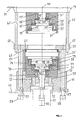
- the device comprises a base plate 11, for example of square configuration, for mounting on the table 13 of a press, a lower coupling plate 15 to be mounted on the injection piston or on the lower ram 17 of the press, an upper coupling plate 19 for mounting at the upper ram 21 of the press, and a die supporting plate 23 located in the space between the base plate 11 and the upper coupling plate 19.
- a lower tool receiving unit 25 is connected with four rods 27 to the coupling plate 15.
- An upper tool receiving unit 29 is connected with the upper coupling plate 90.
- the lower tool receiving unit 25 comprises three tool supports 31,32,33 which may be individually or together moved back and forward by actuating devices, e.g. hydraulic cylinders 37,38,39 parallel to the central axis 40. On the embodiment shown the actuating devices 37,38,39 are integrated in the tool receiving unit.
- the tool supports 31,32,33 are in the form of rings. Several hydraulic cylinders located at equal distances are provided for each tool support.
- a central tool support 41 is provided, which is actuatable by an actuating device 43, e.g. a hydraulic cylinder, of the press.
- an actuating device 43 e.g. a hydraulic cylinder
- an adjustable stop 45,46,47 for the press position is provided.
- an adjustable stop 49,50,51 is provided.
- the adjustable stops may be in the form of threaded rings.
- the upper tool receiving unit 29 is of analogous design as the lower tool receiving unit 25, so that in this respect reference may be had to the lower tool receiving unit 25.
- the same reference numerals are used, but provided with an apostrophe. It is obvious for the man skilled in the art that it is possible to provide the tool receiving units 25, 29 with more or less tool supports.
- the supporting plate 23 may be supported by four rods 55 which are axially movable in the base plate 11.
- the rods 55 may be coupled by coupling members 57 to the hydraulic cylinders 58 of the press.
- the coupling members 57 also act as stops limiting the upper position of the rods 55 and of the die supporting plate 23, respectively.
- FIGS 3 and 4 show, it is also possible to provide the hydraulic cylinders 58 at the device instead at the press.
- a support member 59 with an adjustable stop 61 encircles the lower tool receiving unit 25 close to the center. Between the stop 61 and the die supporting plate 23 is a small gap 63. When during the calibrating operation the pressure on the die 84 reaches a certain value the die supporting plate 23 comes to a rest on the stop 61.
- the adjustable stop 61 can have the form of a threaded ring.
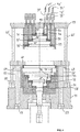
- Fig. 2 shows the device of Fig. 1 with the tool and a workpiece 83 inserted.
- the tool shown comprises the die 84 and the lower and upper stamps 77,78,79; 80,81,82, and the center pin 85.
- FIG. 3 and 4 show a measuring system 69,70,71 and 69',70'71', respectively, can be provided for positioning each tool support 31,32,33; 31',32',33' into the ejecting position. In this case no adjustable stop is necessary for the ejecting position.
- each tool support 31',32',33' is connected to a coupling rod 73,74,75, respectively, which can be actuated by actuating devices, e.g. hydraulic cylinders 37',38',39' of the press.
- actuating devices e.g. hydraulic cylinders 37',38',39' of the press.
- FIG 5 the calibrating operation with a device according to figures 1 and 2 is shown.
- a tool has been inserted into the device.
- the lower part of the tool comprises the stamps 77,78,79 and the upper part the stamps 80,81,82.
- a center pin 85 is provided.
- the workpiece 83 is shown. It has the form of a body of rotation.
- the device serves to receive a tool for calibrating of workpieces 83, preferably workpieces manufactured by a powder metallurgical process.
- the tool comprises the lower stamps 77,78,79 and the upper stamps 80,81,82 located on tool supports 31,32,33; 31',32',33'. These stamps may be moved up and down individually or together parallel to the axis 40. Also movable up and down is the tool support 41 on which, if required, a center pin 85 is mounted.
- the device is particularly suitable for the calibration of complicated workpieces, such as represented for example by the workpiece 83 having the form of a body of rotation.
Landscapes
- Engineering & Computer Science (AREA)
- Mechanical Engineering (AREA)
- Manufacturing & Machinery (AREA)
- Powder Metallurgy (AREA)
- Press Drives And Press Lines (AREA)
- Perforating, Stamping-Out Or Severing By Means Other Than Cutting (AREA)
- Treatment Of Fiber Materials (AREA)
- Forging (AREA)
Abstract
Description
- The invention concerns a device to receive tools for the calibration of workpieces, in particular workpieces manufactured by a powder metallurgical process.
- In powder metallurgical manufacturing of workpieces metallic powder or granulate is first compacted in a die. The object obtained in this way is then sintered in a oven. The workpieces manufactured in this way often do not have the desired dimensional accuracy and quality of the surfaces. In order to improve the dimensional accuracy and the quality of the surfaces it is known to subject the workpieces to a further operation, namely to the so-called calibration. For this purpose the workpiece is placed in a die and subjected to high pressure which may be in the order of 60 KN per cm2. In this way the structure of the workpiece is compacted. Also the quality of the surfaces and the dimensional accuracy will be increased. Up to the present time calibrating was carried out with relatively simple devices. However, in practice these devices are not sufficiently modular and flexible for use with complicated workpieces.
- In the patent literature no devices have been found for receiving tools for the calibration of workpieces. A utility patent under no. DE 90 12 752.8 from the year 1991 discloses an adapter for tools for the manufacturing of workpieces by compacting of metallic powder.
- It is therefore an object of the present invention to create a device which is of modular design, flexible in application and capable to receive a plurality of stamps on different tool planes, so that also complicated workpieces, such as gears or gear segments, can be calibrated.
- According to the invention this is accomplished by a device comprising a base plate for mounting on the table of a press, a lower coupling plate for attachment at the lower ram of the press, an upper coupling plate for attachment at the upper ram of the press, a die supporting plate located between the base plate and the upper coupling plate, a lower tool receiving unit connected to the lower coupling plate and movable as a whole with the corresponding tool supports, and an upper tool receiving unit connected to the upper coupling plate and movable as a whole with the corresponding tool supports, at least one of the tool receiving units comprising several tool supports and an actuating device provided for each tool support for individually moving the tool support back and forth. This device permits calibrating of relatively complicated workpieces as this will be illustrated below. This device allows to individually move the stamps of the tool during the pressing operation. However, on the subsequent ejecting operation all lower stamps will be moved together with the lower ram which permits to free the workpiece and its transfer to a transfer device.
- The lower as well as the upper tool receiving unit preferably comprise several tool supports. However, if it is desired to employ the device for single use with a certain tool for calibrating very large numbers of a certain workpiece for which one part of the tool contains only one stamp eventually only one of both tool receiving units may be provided with several tool supports.
- According to an embodiment of the invention the actuating devices for the tool supports are integrated into the tool receiving unit. In this case the calibration device is substantially independent of the design of the press. However, it is also possible to connect the tool supports to coupling rods which are actuatable by actuating devices of the press.
- The device may contain a central tool support which is actuatable by an actuating device of the press. This central tool support serves to receive the central pin which can engage the central bore of the workpiece, if the workpiece contains such a bore.
- The respective actuating device may be preferably hydraulically actuatable, for example by a hydraulic cylinder.
- An embodiment of the device is characterised in that the die supporting plate is supported by rods which are axially movable in the base plate, and in that the upper position of each rod is limited by a stop. These rods may be connectable to hydraulic cylinders of the press. This device provides that the die supporting plate will be on the same level both on feeding and removing the workpiece. This facilitates automation of these operations. Another embodiment provides that between the base plate and the die supporting plate hydraulic cylinders are located. In both cases a so-called floating support of the die supporting plate is obtained. The die supporting plate is located at a small distance from a support member which encircles the lower tool receiving unit close to the center. Accordingly, if in calibrating the pressure acting on the die supporting plate exceeds a certain limit the die supporting plate comes to a rest on the support member. The central location of the support member has the advantage that the die supporting plate is not inadmissibly bent when the pressure is further increased. The support member is preferably provided with an adjustable stop, e.g. in form of a threaded ring, for the die supporting plate. On a tool change this permits to reduce the change over time, because no special spacers must be inserted. For each tool support an adjustable stop for the press position and for the ejecting position may be provided. However, it is also possible to provide a measuring system instead of a stop for the ejecting position. Such a measuring system may be located in the device itself or in the press. Also these features limit the time necessary for a tool change.
- The invention also concerns a press for calibrating workpieces with a device according to one of the claims 1 to 15. A preferred embodiment of the press is characterised in that the die supporting plate is supported by rods which are axially movable in the base plate, the upper position of each rod being limited by a stop, and each rod being movable by a hydraulic cylinder. Advantageously also a central tool support is provided which may be actuatable, preferably hydraulically, by an actuating device located in the lower ram of the press. Embodiments of the invention will now be described with the reference to the drawing.
- Figure 1
- shows a longitudinal section through the device,
- Figure 2
- shows the device as in figure 1, but with inserted tools and a workpiece located on the die,
- Figure 3
- shows a modified version of the device,
- Figure 4
- shows a further modification of the device, and
- Figure 5
- illustrates the different steps of the calibration operation.
- In order to better represent the inventive features the figures have been somewhat schematised.
- As figures 1 and 2 show, the device comprises a
base plate 11, for example of square configuration, for mounting on the table 13 of a press, alower coupling plate 15 to be mounted on the injection piston or on thelower ram 17 of the press, anupper coupling plate 19 for mounting at theupper ram 21 of the press, and a die supportingplate 23 located in the space between thebase plate 11 and theupper coupling plate 19. - A lower
tool receiving unit 25 is connected with fourrods 27 to thecoupling plate 15. An uppertool receiving unit 29 is connected with the upper coupling plate 90. The lowertool receiving unit 25 comprises three tool supports 31,32,33 which may be individually or together moved back and forward by actuating devices, e.g.hydraulic cylinders central axis 40. On the embodiment shown theactuating devices - Further, a
central tool support 41 is provided, which is actuatable by an actuatingdevice 43, e.g. a hydraulic cylinder, of the press. For each tool support anadjustable stop adjustable stop - In the embodiment shown the upper
tool receiving unit 29 is of analogous design as the lowertool receiving unit 25, so that in this respect reference may be had to the lowertool receiving unit 25. For the corresponding parts the same reference numerals are used, but provided with an apostrophe. It is obvious for the man skilled in the art that it is possible to provide thetool receiving units - The supporting
plate 23 may be supported by fourrods 55 which are axially movable in thebase plate 11. Therods 55 may be coupled by couplingmembers 57 to thehydraulic cylinders 58 of the press. Thecoupling members 57 also act as stops limiting the upper position of therods 55 and of thedie supporting plate 23, respectively. As figures 3 and 4 show, it is also possible to provide thehydraulic cylinders 58 at the device instead at the press. - A
support member 59 with anadjustable stop 61 encircles the lowertool receiving unit 25 close to the center. Between thestop 61 and thedie supporting plate 23 is asmall gap 63. When during the calibrating operation the pressure on thedie 84 reaches a certain value thedie supporting plate 23 comes to a rest on thestop 61. Theadjustable stop 61 can have the form of a threaded ring. - Four
guide columns 65 extending from theupper coupling plate 19 intobores 67 of thedie supporting plate 23 serve to guide the uppertool receiving unit 29 on its movement relative to the lowertool receiving unit 25. - Fig. 2 shows the device of Fig. 1 with the tool and a
workpiece 83 inserted. The tool shown comprises thedie 84 and the lower andupper stamps center pin 85. - As the embodiments according to figure 3 and 4 show a measuring
system tool support - On the embodiment of figure 4 it can be seen that each
tool support 31',32',33' is connected to acoupling rod - It is obvious for the man-skilled in the art that different features shown in the figures 1 to 4 can be differently combined. For example, also on the device of figure 2 the hydraulic cylinders 37',38',39' can be located at the press as in figure 4.
- In figure 5 the calibrating operation with a device according to figures 1 and 2 is shown. A tool has been inserted into the device. The lower part of the tool comprises the
stamps stamps center pin 85 is provided. Also theworkpiece 83 is shown. It has the form of a body of rotation. - The following phases of the calibrating operation are shown:
- a) All stamps are in base position. The
die supporting plate 23 with thedie 84 is in the upper position with agap 63 being visible. Theworkpiece 83 to be calibrated is put on thedie 84. - b) The upper tool is moving downward and pushes the
workpiece 83 into thedie 84. - c) The
workpiece 83 is now under high pressure in press position and the floatingdie supporting plate 23 abuts on thestop 61 of thesupport member 59. - d) The upper tool is moved upward. On this example the
stamps stamp 81 located in between to withdraw from the groove of theworkpiece 83. - e) The calibrated
workpiece 83 is ejected from thedie 84. Allstamps center pin 85 included, are moved upward by thehydraulic cylinder 43. - f) The
center pin 85 is pulled down and the innermost stamp 77 ejects on this example the workpiece. The calibratedworkpiece 83 is now free. - The device serves to receive a tool for calibrating of
workpieces 83, preferably workpieces manufactured by a powder metallurgical process. On the example shown the tool comprises thelower stamps upper stamps axis 40. Also movable up and down is thetool support 41 on which, if required, acenter pin 85 is mounted. The device is particularly suitable for the calibration of complicated workpieces, such as represented for example by theworkpiece 83 having the form of a body of rotation.
Claims (18)
- Device to receive tools for the calibration of workpieces, in particular workpieces manufactured by a powder metallurgical process, comprising
a base plate (11) for mounting on the table (13) of a press,
a lower coupling plate (15) for attachment at the lower ram of the press,
an upper coupling plate (19) for attachment at the upper ram (21) of the press,
a die supporting plate (23) located between the base plate (11) and the upper coupling plate (19),
a lower tool receiving unit (25) connected to the lower coupling plate (15) and movable as a whole with the corresponding tool supports, and
an upper tool receiving unit (29) connected to the upper coupling plate (19) and movable as a whole with the corresponding tool supports,
at least one of the tool receiving units (25,29) comprising several tool supports (31,32,33; 31',32',33') and an actuating device (37,38,39; 3T,38',39') provided for each tool support for individually moving the tool support back and forth. - Device as claimed in claim 1, characterised in that the lower tool receiving unit (25) comprises several tool supports (31,32,33).
- Device as claimed in claim 1 or 2, characterised in that the upper tool receiving unit (29) comprises several tool supports (31',32',33').
- Device as claimed in one of the claims 1 to 3, characterised in that the actuating device (37,38,39; 37',38',39') is integrated into the tool receiving unit (25,29).
- Device as claimed in one of the claims 1 to 4, characterised in that the tool supports (31',32',33') are connected to coupling rods (73,74,75) actuatable by actuating devices (37',38',39') of the press.
- Device as claimed in one of the claims 1 to 5, characterised in that a central tool support (41) is provided which is actuatable by an actuating device of the press.
- Device as claimed in one of the claims 1 to 6, characterised in that the respective actuating device (37,38,39; 37',38',39') is hydraulically actuatable.
- Device as claimed in one of the claims 1 to 6, characterised in that the supporting plate (23) is supported by rods (55) which are axially movable in the base plate (11), and in that the upper position of each rod is limited by a stop (57).
- Device as claimed in claim 8, characterised in that the rods (55) are movable by hydraulic cylinders (58) of the press.
- Device as claimed in one of the claims 1 to 9, characterised in that between the base plate (11) and the die supporting plate (23) hydraulic cylinders (58) are located (Fig. 4).
- Device as claimed in one of the claims 1 to 10, characterised in that a support member (59) for the die supporting plate (23) encircles the lower tool receiving unit (25) close to the center.
- Device as claimed in claim 11, characterised in that at the support member (59) an adjustable stop (61), e.g. in the form of a threaded ring, for the die supporting plate (23) is located.
- Device as claimed in one of the claims 1 to 12, characterised in that for each tool support (31,32,33; 31'32',33') an adjustable stop (45,46,47; 45',46',47) for the press position is provided.
- Device as claimed in one of the claims 1 to 13, characterised in that for each tool support (31,32,33; 31',32',33') an adjustable stop (49,50,51; 49',50',51') for the ejecting position is provided.
- Device as claimed in one of the claims 1 to 13, characterised in that for the positioning of each tool support (31,32,33; 31',32',33') into ejecting position a measuring system (69) is provided.
- Press for calibrating workpieces (83), in particular workpieces manufactured by a powder metallurgical process, with a device according to one of the claims 1 to 15.
- Press according to claim 16, characterised in that the die supporting plate (23) is supported by rods (55) which are axially movable in the base plate (11), the upper position of each rod being limited by a stop (57), and each rod (55) being movable by a hydraulic cylinder (58).
- Press according to claim 16 or 17, characterised in that a central tool support (41) is provided, and in that said central tool support (41) is movable, preferably hydraulically, by an actuating device located in the lower ram (17) of the press.
Priority Applications (1)
| Application Number | Priority Date | Filing Date | Title |
|---|---|---|---|
| PL04761982T PL1677929T3 (en) | 2003-10-29 | 2004-10-28 | Device to receive tools for the calibration of workpieces and press with such a device |
Applications Claiming Priority (2)
| Application Number | Priority Date | Filing Date | Title |
|---|---|---|---|
| CH18412003 | 2003-10-29 | ||
| PCT/CH2004/000650 WO2005039805A2 (en) | 2003-10-29 | 2004-10-28 | Device to receive tools for the calibration of workpieces and press with such a device |
Publications (2)
| Publication Number | Publication Date |
|---|---|
| EP1677929A2 EP1677929A2 (en) | 2006-07-12 |
| EP1677929B1 true EP1677929B1 (en) | 2007-05-16 |
Family
ID=34468801
Family Applications (1)
| Application Number | Title | Priority Date | Filing Date |
|---|---|---|---|
| EP04761982A Expired - Lifetime EP1677929B1 (en) | 2003-10-29 | 2004-10-28 | Device to receive tools for the calibration of workpieces and press with such a device |
Country Status (10)
| Country | Link |
|---|---|
| US (1) | US7494330B2 (en) |
| EP (1) | EP1677929B1 (en) |
| JP (1) | JP2007510060A (en) |
| CN (1) | CN100464903C (en) |
| AT (1) | ATE362410T1 (en) |
| CA (1) | CA2540012C (en) |
| DE (1) | DE602004006527T2 (en) |
| ES (1) | ES2286656T3 (en) |
| PL (1) | PL1677929T3 (en) |
| WO (1) | WO2005039805A2 (en) |
Families Citing this family (7)
| Publication number | Priority date | Publication date | Assignee | Title |
|---|---|---|---|---|
| AT505947B1 (en) * | 2007-11-14 | 2016-04-15 | Miba Sinter Austria Gmbh | COMPRESSION TOOL |
| US8388274B2 (en) | 2010-01-06 | 2013-03-05 | Kennametal Inc. | Round cutting insert with asymmetric chipbreaker feature |
| DE102010051513A1 (en) * | 2010-11-16 | 2012-05-16 | Dorst Technologies Gmbh & Co. Kg | Ceramic powder and / or metal powder press tool, ceramic powder and / or metal powder press, modular system with such a press tool, method for assembling such a press tool |
| DE102015201784A1 (en) * | 2015-02-02 | 2016-08-04 | Gkn Sinter Metals Engineering Gmbh | Shape optimized PM tool components using interconnect technology |
| DE102017114457B4 (en) * | 2017-06-29 | 2019-08-08 | Gkn Sinter Metals Engineering Gmbh | Plane plate of a press tool |
| DE102017114456B4 (en) * | 2017-06-29 | 2019-08-08 | Gkn Sinter Metals Engineering Gmbh | Plane plate of a press tool |
| EP3530448B1 (en) * | 2018-02-26 | 2023-06-21 | Osterwalder AG | Pressing device for a powder press and a tool changing system |
Family Cites Families (10)
| Publication number | Priority date | Publication date | Assignee | Title |
|---|---|---|---|---|
| FR1581771A (en) * | 1968-08-02 | 1969-09-19 | ||
| DE1920969B2 (en) * | 1969-04-24 | 1975-04-30 | Mannesmann Pulvermetall Gmbh, 4050 Moenchengladbach | Stroke limitation in a hydraulic metal powder press |
| JPS5325976B2 (en) * | 1972-04-11 | 1978-07-29 | ||
| JPS59183998A (en) * | 1983-04-02 | 1984-10-19 | Hitachi Powdered Metals Co Ltd | Device for controlling powder molding press |
| DE9012752U1 (en) * | 1990-09-04 | 1990-11-22 | Mannesmann AG, 4000 Düsseldorf | Tool adapter for a press for the production of stepped, dimensionally stable pressed bodies |
| JPH05195011A (en) * | 1991-08-17 | 1993-08-03 | Werkzeugbau Alvier Ag | Modular device for press forming workpieces with helical contours |
| JP3173157B2 (en) * | 1992-07-07 | 2001-06-04 | トヨタ自動車株式会社 | Powder molding equipment |
| JPH0798279B2 (en) * | 1992-11-05 | 1995-10-25 | 株式会社ヨシツカ精機 | Punch connection method and connection device for powder molding press |
| TW287975B (en) * | 1995-11-16 | 1996-10-11 | Honda Motor Co Ltd | Method of and apparatus for manufacturing pressed powder body |
| CN2539625Y (en) * | 2002-02-10 | 2003-03-12 | 台湾良冢精工股份有限公司 | Powder movement adjustment device for powder molding press |
-
2004
- 2004-10-28 WO PCT/CH2004/000650 patent/WO2005039805A2/en not_active Ceased
- 2004-10-28 ES ES04761982T patent/ES2286656T3/en not_active Expired - Lifetime
- 2004-10-28 US US10/577,249 patent/US7494330B2/en not_active Expired - Fee Related
- 2004-10-28 DE DE602004006527T patent/DE602004006527T2/en not_active Expired - Lifetime
- 2004-10-28 AT AT04761982T patent/ATE362410T1/en active
- 2004-10-28 EP EP04761982A patent/EP1677929B1/en not_active Expired - Lifetime
- 2004-10-28 PL PL04761982T patent/PL1677929T3/en unknown
- 2004-10-28 JP JP2006537029A patent/JP2007510060A/en active Pending
- 2004-10-28 CA CA2540012A patent/CA2540012C/en not_active Expired - Fee Related
- 2004-10-28 CN CNB2004800315294A patent/CN100464903C/en not_active Expired - Fee Related
Also Published As
| Publication number | Publication date |
|---|---|
| US20070062244A1 (en) | 2007-03-22 |
| CA2540012C (en) | 2011-10-25 |
| CA2540012A1 (en) | 2005-05-06 |
| WO2005039805A3 (en) | 2005-11-24 |
| ES2286656T3 (en) | 2007-12-01 |
| DE602004006527D1 (en) | 2007-06-28 |
| JP2007510060A (en) | 2007-04-19 |
| PL1677929T3 (en) | 2007-10-31 |
| DE602004006527T2 (en) | 2008-01-24 |
| WO2005039805A2 (en) | 2005-05-06 |
| CN100464903C (en) | 2009-03-04 |
| ATE362410T1 (en) | 2007-06-15 |
| CN1871083A (en) | 2006-11-29 |
| US7494330B2 (en) | 2009-02-24 |
| EP1677929A2 (en) | 2006-07-12 |
Similar Documents
| Publication | Publication Date | Title |
|---|---|---|
| CA1114579A (en) | Multiple punch tool set for powder compacting press | |
| US8523550B2 (en) | Powder press for the manufacture of a metal powder compact | |
| US3561056A (en) | Tool set for powder compacting press | |
| US20130313741A1 (en) | Ceramic-powder and/or metal-powder press tool, ceramic-powder and/or metal-powder press, modular system with such a press tool, method for assembling and operating a ceramic-powder and/or metal-powder press tool or a press | |
| US5049054A (en) | Press having a tool mount to be inserted into the press | |
| CA2540012C (en) | Device to receive tools for the calibration of workpieces and press with such a device | |
| US7059165B2 (en) | Hydromechanical closing device, in particular for lateral extrusion | |
| AU702193B2 (en) | Multi-stage assembling robot | |
| US3640167A (en) | Punching apparatus | |
| US4053267A (en) | Die and punch assembly for compacting powder material | |
| US4456445A (en) | Mounting structure for die, punch and core rod assembly for compacting powder material | |
| GB1170992A (en) | A Powder Compacting Press Unitary Tool Capsule Assembly. | |
| US4427352A (en) | Mounting structure for die, punch and core rod assembly for compacting powder material | |
| US5410946A (en) | Hydraulic actuator | |
| US4347051A (en) | Die and punch assembly for compacting powder material | |
| US20070062248A1 (en) | Press for making a shaped workpiece | |
| US4390335A (en) | Die, punch and core rod assembly for compacting powder material | |
| CN218593767U (en) | Medicine pressing die | |
| SU1496865A1 (en) | Arrangement for expanding tubular billets | |
| RU26758U1 (en) | ELASTIC MEDIA STAMPING DEVICE | |
| CN118080660A (en) | Titanium alloy bottom plate hot-pressing device | |
| WO2003043764A2 (en) | Hydraulic modular manufacturing system | |
| JP2530501B2 (en) | Extrusion press equipment | |
| WO2002040204A2 (en) | Hydraulic modular manufacturing system | |
| JPH08323500A (en) | Upper die holder for transfer press |
Legal Events
| Date | Code | Title | Description |
|---|---|---|---|
| PUAI | Public reference made under article 153(3) epc to a published international application that has entered the european phase |
Free format text: ORIGINAL CODE: 0009012 |
|
| 17P | Request for examination filed |
Effective date: 20060322 |
|
| AK | Designated contracting states |
Kind code of ref document: A2 Designated state(s): AT BE BG CH CY CZ DE DK EE ES FI FR GB GR HU IE IT LI LU MC NL PL PT RO SE SI SK TR |
|
| GRAP | Despatch of communication of intention to grant a patent |
Free format text: ORIGINAL CODE: EPIDOSNIGR1 |
|
| DAX | Request for extension of the european patent (deleted) | ||
| GRAS | Grant fee paid |
Free format text: ORIGINAL CODE: EPIDOSNIGR3 |
|
| GRAA | (expected) grant |
Free format text: ORIGINAL CODE: 0009210 |
|
| AK | Designated contracting states |
Kind code of ref document: B1 Designated state(s): AT BE BG CH CY CZ DE DK EE ES FI FR GB GR HU IE IT LI LU MC NL PL PT RO SE SI SK TR |
|
| PG25 | Lapsed in a contracting state [announced via postgrant information from national office to epo] |
Ref country code: FI Free format text: LAPSE BECAUSE OF FAILURE TO SUBMIT A TRANSLATION OF THE DESCRIPTION OR TO PAY THE FEE WITHIN THE PRESCRIBED TIME-LIMIT Effective date: 20070516 |
|
| REG | Reference to a national code |
Ref country code: GB Ref legal event code: FG4D |
|
| REG | Reference to a national code |
Ref country code: CH Ref legal event code: EP |
|
| REG | Reference to a national code |
Ref country code: IE Ref legal event code: FG4D |
|
| REF | Corresponds to: |
Ref document number: 602004006527 Country of ref document: DE Date of ref document: 20070628 Kind code of ref document: P |
|
| REG | Reference to a national code |
Ref country code: CH Ref legal event code: NV Representative=s name: RIEDERER HASLER & PARTNER PATENTANWAELTE AG |
|
| PG25 | Lapsed in a contracting state [announced via postgrant information from national office to epo] |
Ref country code: SE Free format text: LAPSE BECAUSE OF FAILURE TO SUBMIT A TRANSLATION OF THE DESCRIPTION OR TO PAY THE FEE WITHIN THE PRESCRIBED TIME-LIMIT Effective date: 20070816 |
|
| ET | Fr: translation filed | ||
| REG | Reference to a national code |
Ref country code: PL Ref legal event code: T3 |
|
| NLV1 | Nl: lapsed or annulled due to failure to fulfill the requirements of art. 29p and 29m of the patents act | ||
| REG | Reference to a national code |
Ref country code: ES Ref legal event code: FG2A Ref document number: 2286656 Country of ref document: ES Kind code of ref document: T3 |
|
| PG25 | Lapsed in a contracting state [announced via postgrant information from national office to epo] |
Ref country code: BE Free format text: LAPSE BECAUSE OF FAILURE TO SUBMIT A TRANSLATION OF THE DESCRIPTION OR TO PAY THE FEE WITHIN THE PRESCRIBED TIME-LIMIT Effective date: 20070516 |
|
| PG25 | Lapsed in a contracting state [announced via postgrant information from national office to epo] |
Ref country code: PT Free format text: LAPSE BECAUSE OF FAILURE TO SUBMIT A TRANSLATION OF THE DESCRIPTION OR TO PAY THE FEE WITHIN THE PRESCRIBED TIME-LIMIT Effective date: 20071016 Ref country code: SI Free format text: LAPSE BECAUSE OF FAILURE TO SUBMIT A TRANSLATION OF THE DESCRIPTION OR TO PAY THE FEE WITHIN THE PRESCRIBED TIME-LIMIT Effective date: 20070516 Ref country code: DK Free format text: LAPSE BECAUSE OF FAILURE TO SUBMIT A TRANSLATION OF THE DESCRIPTION OR TO PAY THE FEE WITHIN THE PRESCRIBED TIME-LIMIT Effective date: 20070516 Ref country code: NL Free format text: LAPSE BECAUSE OF FAILURE TO SUBMIT A TRANSLATION OF THE DESCRIPTION OR TO PAY THE FEE WITHIN THE PRESCRIBED TIME-LIMIT Effective date: 20070516 Ref country code: BG Free format text: LAPSE BECAUSE OF FAILURE TO SUBMIT A TRANSLATION OF THE DESCRIPTION OR TO PAY THE FEE WITHIN THE PRESCRIBED TIME-LIMIT Effective date: 20070816 |
|
| PLBE | No opposition filed within time limit |
Free format text: ORIGINAL CODE: 0009261 |
|
| STAA | Information on the status of an ep patent application or granted ep patent |
Free format text: STATUS: NO OPPOSITION FILED WITHIN TIME LIMIT |
|
| 26N | No opposition filed |
Effective date: 20080219 |
|
| PG25 | Lapsed in a contracting state [announced via postgrant information from national office to epo] |
Ref country code: GR Free format text: LAPSE BECAUSE OF FAILURE TO SUBMIT A TRANSLATION OF THE DESCRIPTION OR TO PAY THE FEE WITHIN THE PRESCRIBED TIME-LIMIT Effective date: 20070817 |
|
| PG25 | Lapsed in a contracting state [announced via postgrant information from national office to epo] |
Ref country code: RO Free format text: LAPSE BECAUSE OF FAILURE TO SUBMIT A TRANSLATION OF THE DESCRIPTION OR TO PAY THE FEE WITHIN THE PRESCRIBED TIME-LIMIT Effective date: 20070516 Ref country code: MC Free format text: LAPSE BECAUSE OF NON-PAYMENT OF DUE FEES Effective date: 20071031 |
|
| PG25 | Lapsed in a contracting state [announced via postgrant information from national office to epo] |
Ref country code: IE Free format text: LAPSE BECAUSE OF NON-PAYMENT OF DUE FEES Effective date: 20071030 |
|
| PG25 | Lapsed in a contracting state [announced via postgrant information from national office to epo] |
Ref country code: EE Free format text: LAPSE BECAUSE OF FAILURE TO SUBMIT A TRANSLATION OF THE DESCRIPTION OR TO PAY THE FEE WITHIN THE PRESCRIBED TIME-LIMIT Effective date: 20070516 |
|
| PG25 | Lapsed in a contracting state [announced via postgrant information from national office to epo] |
Ref country code: CY Free format text: LAPSE BECAUSE OF FAILURE TO SUBMIT A TRANSLATION OF THE DESCRIPTION OR TO PAY THE FEE WITHIN THE PRESCRIBED TIME-LIMIT Effective date: 20070516 |
|
| PG25 | Lapsed in a contracting state [announced via postgrant information from national office to epo] |
Ref country code: LU Free format text: LAPSE BECAUSE OF NON-PAYMENT OF DUE FEES Effective date: 20071028 |
|
| PG25 | Lapsed in a contracting state [announced via postgrant information from national office to epo] |
Ref country code: HU Free format text: LAPSE BECAUSE OF FAILURE TO SUBMIT A TRANSLATION OF THE DESCRIPTION OR TO PAY THE FEE WITHIN THE PRESCRIBED TIME-LIMIT Effective date: 20071117 |
|
| PGFP | Annual fee paid to national office [announced via postgrant information from national office to epo] |
Ref country code: PL Payment date: 20101014 Year of fee payment: 7 |
|
| PGFP | Annual fee paid to national office [announced via postgrant information from national office to epo] |
Ref country code: TR Payment date: 20101013 Year of fee payment: 7 |
|
| PGFP | Annual fee paid to national office [announced via postgrant information from national office to epo] |
Ref country code: FR Payment date: 20111103 Year of fee payment: 8 Ref country code: CZ Payment date: 20111024 Year of fee payment: 8 |
|
| REG | Reference to a national code |
Ref country code: FR Ref legal event code: ST Effective date: 20130628 |
|
| PG25 | Lapsed in a contracting state [announced via postgrant information from national office to epo] |
Ref country code: CZ Free format text: LAPSE BECAUSE OF NON-PAYMENT OF DUE FEES Effective date: 20121028 |
|
| PG25 | Lapsed in a contracting state [announced via postgrant information from national office to epo] |
Ref country code: FR Free format text: LAPSE BECAUSE OF NON-PAYMENT OF DUE FEES Effective date: 20121031 |
|
| PGFP | Annual fee paid to national office [announced via postgrant information from national office to epo] |
Ref country code: GB Payment date: 20131021 Year of fee payment: 10 Ref country code: SK Payment date: 20131025 Year of fee payment: 10 |
|
| REG | Reference to a national code |
Ref country code: PL Ref legal event code: LAPE |
|
| PG25 | Lapsed in a contracting state [announced via postgrant information from national office to epo] |
Ref country code: PL Free format text: LAPSE BECAUSE OF NON-PAYMENT OF DUE FEES Effective date: 20121028 Ref country code: TR Free format text: LAPSE BECAUSE OF NON-PAYMENT OF DUE FEES Effective date: 20121028 |
|
| GBPC | Gb: european patent ceased through non-payment of renewal fee |
Effective date: 20141028 |
|
| REG | Reference to a national code |
Ref country code: SK Ref legal event code: MM4A Ref document number: E 2218 Country of ref document: SK Effective date: 20141028 |
|
| PG25 | Lapsed in a contracting state [announced via postgrant information from national office to epo] |
Ref country code: GB Free format text: LAPSE BECAUSE OF NON-PAYMENT OF DUE FEES Effective date: 20141028 Ref country code: SK Free format text: LAPSE BECAUSE OF NON-PAYMENT OF DUE FEES Effective date: 20141028 |
|
| PGFP | Annual fee paid to national office [announced via postgrant information from national office to epo] |
Ref country code: DE Payment date: 20191021 Year of fee payment: 16 |
|
| PGFP | Annual fee paid to national office [announced via postgrant information from national office to epo] |
Ref country code: ES Payment date: 20191122 Year of fee payment: 16 Ref country code: IT Payment date: 20191028 Year of fee payment: 16 |
|
| PGFP | Annual fee paid to national office [announced via postgrant information from national office to epo] |
Ref country code: CH Payment date: 20191031 Year of fee payment: 16 Ref country code: AT Payment date: 20191022 Year of fee payment: 16 |
|
| REG | Reference to a national code |
Ref country code: DE Ref legal event code: R119 Ref document number: 602004006527 Country of ref document: DE |
|
| REG | Reference to a national code |
Ref country code: CH Ref legal event code: PL |
|
| REG | Reference to a national code |
Ref country code: AT Ref legal event code: MM01 Ref document number: 362410 Country of ref document: AT Kind code of ref document: T Effective date: 20201028 |
|
| PG25 | Lapsed in a contracting state [announced via postgrant information from national office to epo] |
Ref country code: DE Free format text: LAPSE BECAUSE OF NON-PAYMENT OF DUE FEES Effective date: 20210501 |
|
| PG25 | Lapsed in a contracting state [announced via postgrant information from national office to epo] |
Ref country code: AT Free format text: LAPSE BECAUSE OF NON-PAYMENT OF DUE FEES Effective date: 20201028 Ref country code: CH Free format text: LAPSE BECAUSE OF NON-PAYMENT OF DUE FEES Effective date: 20201031 Ref country code: LI Free format text: LAPSE BECAUSE OF NON-PAYMENT OF DUE FEES Effective date: 20201031 |
|
| PG25 | Lapsed in a contracting state [announced via postgrant information from national office to epo] |
Ref country code: IT Free format text: LAPSE BECAUSE OF NON-PAYMENT OF DUE FEES Effective date: 20201028 |
|
| REG | Reference to a national code |
Ref country code: ES Ref legal event code: FD2A Effective date: 20220127 |
|
| PG25 | Lapsed in a contracting state [announced via postgrant information from national office to epo] |
Ref country code: ES Free format text: LAPSE BECAUSE OF NON-PAYMENT OF DUE FEES Effective date: 20201029 |