EP1677529A2 - Device and method for arranging a flat panel display - Google Patents
Device and method for arranging a flat panel display Download PDFInfo
- Publication number
- EP1677529A2 EP1677529A2 EP05028261A EP05028261A EP1677529A2 EP 1677529 A2 EP1677529 A2 EP 1677529A2 EP 05028261 A EP05028261 A EP 05028261A EP 05028261 A EP05028261 A EP 05028261A EP 1677529 A2 EP1677529 A2 EP 1677529A2
- Authority
- EP
- European Patent Office
- Prior art keywords
- bracket
- display device
- display
- installation apparatus
- supporting surface
- Prior art date
- Legal status (The legal status is an assumption and is not a legal conclusion. Google has not performed a legal analysis and makes no representation as to the accuracy of the status listed.)
- Withdrawn
Links
Images


Classifications
-
- H—ELECTRICITY
- H04—ELECTRIC COMMUNICATION TECHNIQUE
- H04N—PICTORIAL COMMUNICATION, e.g. TELEVISION
- H04N5/00—Details of television systems
- H04N5/64—Constructional details of receivers, e.g. cabinets or dust covers
-
- F—MECHANICAL ENGINEERING; LIGHTING; HEATING; WEAPONS; BLASTING
- F16—ENGINEERING ELEMENTS AND UNITS; GENERAL MEASURES FOR PRODUCING AND MAINTAINING EFFECTIVE FUNCTIONING OF MACHINES OR INSTALLATIONS; THERMAL INSULATION IN GENERAL
- F16M—FRAMES, CASINGS OR BEDS OF ENGINES, MACHINES OR APPARATUS, NOT SPECIFIC TO ENGINES, MACHINES OR APPARATUS PROVIDED FOR ELSEWHERE; STANDS; SUPPORTS
- F16M11/00—Stands or trestles as supports for apparatus or articles placed thereon Stands for scientific apparatus such as gravitational force meters
- F16M11/02—Heads
- F16M11/18—Heads with mechanism for moving the apparatus relatively to the stand
-
- F—MECHANICAL ENGINEERING; LIGHTING; HEATING; WEAPONS; BLASTING
- F16—ENGINEERING ELEMENTS AND UNITS; GENERAL MEASURES FOR PRODUCING AND MAINTAINING EFFECTIVE FUNCTIONING OF MACHINES OR INSTALLATIONS; THERMAL INSULATION IN GENERAL
- F16M—FRAMES, CASINGS OR BEDS OF ENGINES, MACHINES OR APPARATUS, NOT SPECIFIC TO ENGINES, MACHINES OR APPARATUS PROVIDED FOR ELSEWHERE; STANDS; SUPPORTS
- F16M11/00—Stands or trestles as supports for apparatus or articles placed thereon Stands for scientific apparatus such as gravitational force meters
- F16M11/02—Heads
- F16M11/04—Means for attachment of apparatus; Means allowing adjustment of the apparatus relatively to the stand
- F16M11/06—Means for attachment of apparatus; Means allowing adjustment of the apparatus relatively to the stand allowing pivoting
- F16M11/08—Means for attachment of apparatus; Means allowing adjustment of the apparatus relatively to the stand allowing pivoting around a vertical axis, e.g. panoramic heads
-
- F—MECHANICAL ENGINEERING; LIGHTING; HEATING; WEAPONS; BLASTING
- F16—ENGINEERING ELEMENTS AND UNITS; GENERAL MEASURES FOR PRODUCING AND MAINTAINING EFFECTIVE FUNCTIONING OF MACHINES OR INSTALLATIONS; THERMAL INSULATION IN GENERAL
- F16M—FRAMES, CASINGS OR BEDS OF ENGINES, MACHINES OR APPARATUS, NOT SPECIFIC TO ENGINES, MACHINES OR APPARATUS PROVIDED FOR ELSEWHERE; STANDS; SUPPORTS
- F16M11/00—Stands or trestles as supports for apparatus or articles placed thereon Stands for scientific apparatus such as gravitational force meters
- F16M11/02—Heads
- F16M11/04—Means for attachment of apparatus; Means allowing adjustment of the apparatus relatively to the stand
- F16M11/06—Means for attachment of apparatus; Means allowing adjustment of the apparatus relatively to the stand allowing pivoting
- F16M11/10—Means for attachment of apparatus; Means allowing adjustment of the apparatus relatively to the stand allowing pivoting around a horizontal axis
-
- F—MECHANICAL ENGINEERING; LIGHTING; HEATING; WEAPONS; BLASTING
- F16—ENGINEERING ELEMENTS AND UNITS; GENERAL MEASURES FOR PRODUCING AND MAINTAINING EFFECTIVE FUNCTIONING OF MACHINES OR INSTALLATIONS; THERMAL INSULATION IN GENERAL
- F16M—FRAMES, CASINGS OR BEDS OF ENGINES, MACHINES OR APPARATUS, NOT SPECIFIC TO ENGINES, MACHINES OR APPARATUS PROVIDED FOR ELSEWHERE; STANDS; SUPPORTS
- F16M11/00—Stands or trestles as supports for apparatus or articles placed thereon Stands for scientific apparatus such as gravitational force meters
- F16M11/02—Heads
- F16M11/04—Means for attachment of apparatus; Means allowing adjustment of the apparatus relatively to the stand
- F16M11/06—Means for attachment of apparatus; Means allowing adjustment of the apparatus relatively to the stand allowing pivoting
- F16M11/12—Means for attachment of apparatus; Means allowing adjustment of the apparatus relatively to the stand allowing pivoting in more than one direction
- F16M11/126—Means for attachment of apparatus; Means allowing adjustment of the apparatus relatively to the stand allowing pivoting in more than one direction for tilting and panning
-
- F—MECHANICAL ENGINEERING; LIGHTING; HEATING; WEAPONS; BLASTING
- F16—ENGINEERING ELEMENTS AND UNITS; GENERAL MEASURES FOR PRODUCING AND MAINTAINING EFFECTIVE FUNCTIONING OF MACHINES OR INSTALLATIONS; THERMAL INSULATION IN GENERAL
- F16M—FRAMES, CASINGS OR BEDS OF ENGINES, MACHINES OR APPARATUS, NOT SPECIFIC TO ENGINES, MACHINES OR APPARATUS PROVIDED FOR ELSEWHERE; STANDS; SUPPORTS
- F16M13/00—Other supports for positioning apparatus or articles; Means for steadying hand-held apparatus or articles
- F16M13/02—Other supports for positioning apparatus or articles; Means for steadying hand-held apparatus or articles for supporting on, or attaching to, an object, e.g. tree, gate, window-frame, cycle
-
- H—ELECTRICITY
- H04—ELECTRIC COMMUNICATION TECHNIQUE
- H04N—PICTORIAL COMMUNICATION, e.g. TELEVISION
- H04N9/00—Details of colour television systems
- H04N9/12—Picture reproducers
- H04N9/31—Projection devices for colour picture display, e.g. using electronic spatial light modulators [ESLM]
- H04N9/3179—Video signal processing therefor
- H04N9/3185—Geometric adjustment, e.g. keystone or convergence
Definitions
- the invention relates to installing a flat panel display device. It also relates to aligning a component or components along a preferred plane to provide an optimal viewing experience.
- these new digital displays are much lighter and take up less space than their similarly sized analog predecessors. Accordingly, they can be installed in many different ways. For example, flat panel displays can be hung directly on a wall, while a DLPTM projector can be paired with a movie screen and be used like a slide projector or mounted from the ceiling. These installations ensure that the room where the home entertainment system is located is not cluttered with bulky equipment. On the other hand, these arrangements can be difficult to install and an a mistake by an unskilled installer or a do-it-yourselfer may result in a display that is slightly askew, i.e. not installed at a proper viewing angle.
- the invention may address these problems by facilitating the installation of a display at a proper angle.
- the invention can also facilitate the display of video at a proper alignment angle even if the installation of the display is improper.
- the invention may be suitable for the integrated multimedia system like the one described in U.S. Patent Application No. 11/198,356 filed August 8, 2005, which is hereby incorporated by reference in its entirety.
- the invention provides an adjustable bracket for mounting a display device that includes a faceplate having an interface corresponding to a mounting position on a display device; a plurality of holes adapted to receive a fastener disposed on the face plate; and a level device disposed on the face plate.
- the level device indicates that an edge of the faceplate is substantially level.
- the invention also provides a removable display device installation apparatus, which includes a floor stand surface that supports the installation stand on a supporting surface; and a display support surface coupled to the floor stand surface that supports a display device above the supporting surface.
- the display support surface is substantially parallel to the floor stand surface.
- the display support surface of the installation stand aligns a bottom surface of the display device on a plane substantially parallel to the supporting surface.
- a method of mounting a display device includes placing an installation apparatus on a supporting surface to align the supporting apparatus on a plane substantially parallel to the supporting surface; providing a bracket structure adapted to receive the display device coupled with the installation apparatus; and mounting the display device onto the bracket to secure the display device to a mounting surface substantially perpendicular to the supporting surface. An edge of the display device is substantially parallel to the supporting surface.
- the invention discloses a display device installation apparatus that includes a bracket adapted to receive a display device and a floor stand coupled to the bracket.
- the floor stand is substantially parallel to the bracket
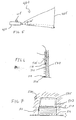
- FIG. 1 illustrates a plan view illustrating the alignment of a projector and a viewing screen according to an embodiment of the invention.
- FIG. 2 illustrates a plan view of a leveling device included in a viewing screen.
- FIG. 2A illustrates a close-up view of the area "A" of FIG. 2.
- FIG. 3 illustrates a front elevational view of a leveling device included in a mounting bracket according to another embodiment of the invention.
- FIG. 4 illustrates a front elevational front view showing an operation of the mounting bracket from FIG. 3.
- FIG. 5 illustrates a side elevational view showing an image correction system according to an embodiment of the invention.
- FIG. 5A illustrates a side elevational view of a vertical adjustment of a projector according to an embodiment of the invention.
- FIG. 5B illustrates a plan view of a horizontal adjustment of the projector according to an embodiment of the invention.
- FIG. 5C illustrates a side elevational view of a vertical adjustment of a projector according to another embodiment of the invention.
- FIG. 6 illustrates a side elevational view of a removable installation apparatus according to an embodiment of the invention.
- FIG. 6A, 6B, 6C, and 6D illustrate perspective views of various stages of mounting a flat panel display against a wall using the removable installation apparatus of FIG. 6.
- FIG. 7 illustrates a front elevational view of the removable installation apparatus of FIG. 6 and a plane associated therewith.
- FIG. 8 illustrates a front elevational view of a flat panel display disposed behind a lowered viewing screen according to an embodiment of the invention.
- FIG. 8A illustrates a side elevational view of the flat panel display and lowered viewing screen of FIG. 8.
- FIG. 9 illustrates a front elevational view of a flat panel display and raised viewing screen disposed in a housing according to an embodiment of the invention.
- FIG. 9A illustrates a side elevational view of the flat panel display and raised viewing screen of FIG. 9.
- an alignment system 100 includes a viewing screen 105 and a display device 110.
- a typical viewing screen that is well-known to those having ordinary skill in the art is used for screen 105, and a DLPTM projector mounted on a ceiling is used as display device 110.
- the screen 105 includes an emitter 115, which can be a laser, a radio transmitter, or other emission device.
- the emitter 115 may be located on a housing 107 of the screen 105 that comprises a motor (not shown) for raising and lowering the screen.
- the power supply could be a small battery or be a power source that drives the motor if the screen is motorized to draw up and down.
- the display device 110 may include a receptor 120 that receives the emission, also known as a medium, be it light, laser, or a radio signal, from emitter 115. However, the display device 110 can be manually located using the signal coming from the emitter.
- receptor 120 After receiving the emission, receptor 120 delivers it to an alignment processor (not shown) that can determine if the display device 110 is properly aligned with the screen 105. After processing the received emission, the invention can then provide feedback whether the screen 105 and display device 110 are aligned. Such feedback can be provided by sound, visually through an indicator light or a display screen located on the display device 110, or other feedback mechanism known to those skilled in the art. Using such an alignment system 100, it may be easily determined whether display device 110 is properly aligned with viewing screen 105.
- the location of emitter and the receptor can be switched so that emitter 115 is included with display device 110 and the receptor 120 is included with screen 105.
- the screen could be manually located using the signal coming from the emitter of the display device 110.
- the feedback mechanism could be easily provided on the housing 107 of screen 105.
- the invention also discloses a device that facilitates the level installation of a viewing screen 205, which includes a level device 225.
- the screen 205 includes a housing 207, which may or may not be motorized, on which the level device 225 is disposed.
- the level device 225 may comprise an indicator 230 and a pair of level lines 235.
- the level device may operate like a typical level, wherein the level device indicates levelness by the location of the indicator 230 in relation to the level lines 235. Generally, a level position is indicated when the indicator 230 is about centered between the level lines. Any other types of level devices, including but not limited to, laser level, could also be used.
- FIG. 3 and FIG. 4 show a similar approach to provide a level position indication when hanging a flat panel display on a wall.
- a mounting bracket 300 is provided that includes a level device 325.
- the bracket 300 has an interface (not shown) that is coupled with a flat panel display (not shown) at a predetermined mounting position thereon, which is suitable for adequately supporting the flat display device on a wall, for example.
- One or more brackets may be used depending on a number of factors, like the size of the display or the desired bracket size.
- the level device 325 includes an indicator 330 and level lines 335 that operate to indicate a level position similar to the level device 225. Also, any types of level devices, including but not limited to a laser level, could be used.
- the bracket 300 also includes mounting holes 307 that are adapted to receive a fastener 311, like a screw, to fasten the bracket faceplate 303 securely against a wall or other supporting surface to support the weight of a flat panel display.
- the width of hole 307 is narrower than the head of fastener 311 and substantially the same width as the fastener body, but the height of hole 307 is elongated.
- the fastener 311 can be used with other structures, like a washer or a bolt, as well as other structures that are well-known in the fastening art, to assist the securing of the bracket.
- This arrangement allows the fastener 311 to securely fasten bracket 300 when the head of the fastener 311 is in contact with faceplate 303 to secure the bracket against the wall.
- This arrangement also allows the position of bracket 300 to be adjusted when the fastener 311 is loosened. Any other mechanisms that could make a small adjustment, including but not limited to, a bracket, a latch, or a hinge could be used.
- the level device shows a non-level position. Because the mounting position on the display is designed to fit the bracket, then if the bracket 300 is level then the mounted display should also be substantially level. Thus, an installer may loosen a fastener 311 to adjust the bracket into a level position. One or more fasteners 311 may be loosened to allow the installer to adjust the faceplate 303 until the indicator 330 is between level lines 335 to indicate a level position. Subsequently, the installer may tighten the fasteners 311 to secure bracket 300 in a level position.
- a level position indicator with an adjustment mechanism, an installation of a flat display panel in a level position is facilitated.
- the flat panel display could be attached to the bracket, using the attachment mechanism between the flat panel display and the bracket.
- FIG. 5 illustrates a system for providing an adjustment for a display projector, wherein the adjustment aligns the projected display onto a viewing screen similar to the one illustrated in FIG. 1.
- the adjustment system 400 comprises a screen 405 and a display projector 410, which comprises an image capture device 415.
- the image capture device 415 is mounted on the projector, which may be mounted from the ceiling or placed on a table top or located in a console.
- the angle of projection shown here is from the table top/console position.
- the angle of projection is inverted when projector is mounted from the ceiling.
- the dotted line illustrates the optical center of the projection lens of projector 410.
- projector 410 has a primary projection angle ⁇ of 30 degrees in relation to the lens is shown, as wells as a secondary angle ⁇ of 5 degrees. These angles may vary and are used only for illustrative purposes.
- the image capture device 415 which is a camera here, captures the screen image and provides this image to an adjustment processor (not shown).
- the adjustment processor may process the screen image, as well as the actual image projected by projector 410, and provide a signal adjustment to a lens shifter that will center the image in relation to the screen 405 both along a vertical axis (floor-to-ceiling) and a horizontal axis (wall-to-wall).
- the image capture device 415 and adjustment processor can be either an integral part of the projector 410 or added later.
- a separate device may also be provided in lieu or a lens shifter that moves the entire projector 410 so that the projected image is centered on screen 405.
- a pod 420 on a table top/console could raise and lower the projector 410 using a projecting portion 425 to provide an adjustment along the vertical axis, and the pod could rotate or tilt (not shown) the projector 410 to provide an adjustment along the horizontal axis.
- FIG. 5A shows the projector 410 adjusted to a raised position 410' (outlined by a broken line) to make a vertical adjustment.
- FIG. 5B shows the projector adjusted to as rotated position 410" (outlined by a broken line) to make a horizontal adjustment.
- a telescopic post 430 could raise and lower the projector 410 using a telescopic portion 435to provide the vertical axis adjustment, and the telescopic post could rotate the projector 410 to provide the horizontal axis adjustment.
- FIG. 5C shows the projector 410 adjusted to a lowered position 410''' (outlined by a broken line) to make a vertical adjustment.
- the pod/post 420 or 430 is used for vertical axis adjustment and a lens shifter is used for horizontal axis adjustment.
- user input such as a remote control device, for example, could be used to manually adjust the projected image to fit the screen.
- adjustment system 400 facilitates the orientation of a projected display on a viewing screen 405.
- FIG. 6 and FIG. 7 illustrate a removable installation apparatus 515 for installing a viewing screen or a flat panel display 505 at the same angle as the floor.
- FIG. 6A through FIG. 6D illustrate mounting a flat panel display using the removable installation apparatus.
- the installation device 515 addresses this by providing a reference to the floor angle during installation.
- the removable installation apparatus 515 comprises a display supporting surface 517 and a floor stand 519, which are parallel to one another.
- the floor stand 519 rests on floor 520 to align the display supporting surface 517 on the same angle as the floor 520.
- the display 505 or bracket 503 can rest on the display supporting surface 517 during installation of display 505 onto a mounting surface like a wall 530 using bracket 503.
- the bracket 503 may include a similar arrangement as the bracket illustrated in FIG. 3 to permit an adjustment of the display's 505 mounting position.
- FIG. 6A shows bracket 503 resting on display supporting surface 517 of installa, while bracket 503 is secured to the wall 530 using fasteners 511 inserted through bracket holes 507.
- the display supporting surface 517 has a very narrow depth so that the installation apparatus 515 does extend too far from the wall 530.
- FIG. 6B shows the bracket 503 secured in place, wherein a bottom surface of the bracket 503 is arranged on a plane substantially parallel to the plane of the display supporting surface 517, the portion of floor stand 519 resting on floor 520, and the floor itself.
- the brackets are fixed to the wall in parallel with the floor surface, once the integrated structure stands again the wall. Then, the lower part can be removed except for the bracket.
- FIG. 6C shows that the removable installation apparatus 515 can be removed because the bracket 503 is secured to wall 530 by fasteners 511.
- FIG. 6D shows the display device 505 mounted on the bracket 503 using a pre-set mounting position of the display 505 adapted for the bracket 503.
- the bottom edge of the display 505 is substantially parallel to the bottom edge of the bracket 505, and thus is substantially parallel to the floor 520.
- the bracket 503 can be coupled to the installation apparatus 515, or formed integrally therewith, to form a unitary bracket/ installation apparatus.
- the display supporting surface 517 can be eliminated but the reference angle to floor 520 is still provided because the bracket is coupled to the floor stand 519 resting on the floor.
- the bracket portion is disposed at an angle substantially the same as the angle of the floor, which orients the display device at the angle of the floor as well.
- the level plane is designated at a plane L.
- display supporting surface 517 or display bracket 503 is disposed on a plane L" that is at the same angle as the plane L' of floor 520 and floor stand 519.
- the bottom of display 505 will also be disposed along L" when it is supported on the installation stand 515 or attached to the bracket 503.
- the installation apparatus 515 can either be removed or left in place as furniture to hold other multimedia components, home décor, or the like.
- the apparatus 515 is no longer needed to support the display 505 since it is mounted on the wall 530 with brackets 503. Because the display supporting surface 517 or the bracket 503 is on the same angle as the floor 520, the display will be oriented at the same angle as the user's viewing angle.
- FIG. 8 and FIG. 8A show a lowered viewing screen 205 used with a flat panel display 505, while FIG. 9 and FIG. 9A illustrate a raised viewing screen 205 disposed in motorized housing 207 used with a flat panel display 505.
- the viewing screen 205 may have a level device 225 as illustrated in FIG. 2.
- a user may want to use different types of displays depending on the video source and the viewing conditions. For example, a viewer may want to use the viewing screen 205 at night or for movies, while the user may want to use the flat panel display 505 during the day or for television programs.
- FIG. 8 shows that the flat panel display 505 (outlined by the broken line) can sit behind the viewing screen 205 when a projection display device is used
- FIG. 8A shows a clearance between the viewing screen 205 and flat panel display 505.
- FIG. 9 and FIG. 9A show the screen 205 can be easily raised when the user wishes to view the flat panel display 505.
- the installation apparatus 515 requires a narrow depth so as to not extend too far from the wall 530. This may be necessary so that it will not interfere with screen 205 if the removable installation apparatus 515 is not removed after installation of the flat panel display 505.
Abstract
Description
- This application claims the benefit of and priority to U.S. Provisional Patent Application No. 60/640,085 filed December 30, 2004 with the U.S. Patent and Trademark Office, the disclosure of which is incorporated by reference in its entirety herein.
- The invention relates to installing a flat panel display device. It also relates to aligning a component or components along a preferred plane to provide an optimal viewing experience.
- Until fairly recently, a consumer only had the choice of using a typical cathode-ray tube television or an analog big screen projection television for use as a display in a home entertainment or home theater system. The advent of the many digital displays, which include flat panel displays like plasma display devices (PDPs) and liquid crystal displays (LCDs), as well as digital projection technologies, like digital light processing (DLP™), now provide may options for the home user.
- Normally, these new digital displays are much lighter and take up less space than their similarly sized analog predecessors. Accordingly, they can be installed in many different ways. For example, flat panel displays can be hung directly on a wall, while a DLP™ projector can be paired with a movie screen and be used like a slide projector or mounted from the ceiling. These installations ensure that the room where the home entertainment system is located is not cluttered with bulky equipment. On the other hand, these arrangements can be difficult to install and an a mistake by an unskilled installer or a do-it-yourselfer may result in a display that is slightly askew, i.e. not installed at a proper viewing angle.
- Thus, there is a need for making the installation easier to ensure a proper installation of these digital displays. That way, the user who has invested considerable time and money in acquiring and/or setting up a home entertainment or home theater system does not get stuck with a "crooked" display. Alternatively, there is a demand for providing a way of compensating for any mistakes in installing a digital display, so that the home entertainment system user may still enjoy a high-end multimedia experience.
- Accordingly, the invention may address these problems by facilitating the installation of a display at a proper angle. The invention can also facilitate the display of video at a proper alignment angle even if the installation of the display is improper. The invention may be suitable for the integrated multimedia system like the one described in U.S. Patent Application No. 11/198,356 filed August 8, 2005, which is hereby incorporated by reference in its entirety.
- The invention provides an adjustable bracket for mounting a display device that includes a faceplate having an interface corresponding to a mounting position on a display device; a plurality of holes adapted to receive a fastener disposed on the face plate; and a level device disposed on the face plate. The level device indicates that an edge of the faceplate is substantially level.
- The invention also provides a removable display device installation apparatus, which includes a floor stand surface that supports the installation stand on a supporting surface; and a display support surface coupled to the floor stand surface that supports a display device above the supporting surface. The display support surface is substantially parallel to the floor stand surface. The display support surface of the installation stand aligns a bottom surface of the display device on a plane substantially parallel to the supporting surface..
- Also, a method of mounting a display device is disclosed. The method includes placing an installation apparatus on a supporting surface to align the supporting apparatus on a plane substantially parallel to the supporting surface; providing a bracket structure adapted to receive the display device coupled with the installation apparatus; and mounting the display device onto the bracket to secure the display device to a mounting surface substantially perpendicular to the supporting surface. An edge of the display device is substantially parallel to the supporting surface.
- Moreover, the invention discloses a display device installation apparatus that includes a bracket adapted to receive a display device and a floor stand coupled to the bracket. The floor stand is substantially parallel to the bracket
- Additional features and embodiments of the invention may be set forth or apparent from consideration of the following detailed description, drawings, and claims. Moreover, it is to be understood that both the foregoing summary of the invention and the following detailed description are exemplary and intended to provide further explanation without limiting the scope of the invention as claimed. For example, while the invention was developed to solve certain problems related to installing digital displays, it may be used in other applications and with other devices where aligning components is desirable.
- The accompanying drawings, which are included to provide a further understanding of the invention, are incorporated in and constitute a part of this specification, illustrate embodiments of the invention, and together with the detailed description serve to explain principles of the invention. No attempt is made to show structural details of the invention in more detail than may be necessary for a fundamental understanding of the invention and the various ways in which it may be practiced.
- FIG. 1 illustrates a plan view illustrating the alignment of a projector and a viewing screen according to an embodiment of the invention.
- FIG. 2 illustrates a plan view of a leveling device included in a viewing screen.
- FIG. 2A illustrates a close-up view of the area "A" of FIG. 2.
- FIG. 3 illustrates a front elevational view of a leveling device included in a mounting bracket according to another embodiment of the invention.
- FIG. 4 illustrates a front elevational front view showing an operation of the mounting bracket from FIG. 3.
- FIG. 5 illustrates a side elevational view showing an image correction system according to an embodiment of the invention.
- FIG. 5A illustrates a side elevational view of a vertical adjustment of a projector according to an embodiment of the invention.
- FIG. 5B illustrates a plan view of a horizontal adjustment of the projector according to an embodiment of the invention.
- FIG. 5C illustrates a side elevational view of a vertical adjustment of a projector according to another embodiment of the invention.
- FIG. 6 illustrates a side elevational view of a removable installation apparatus according to an embodiment of the invention.
- FIG. 6A, 6B, 6C, and 6D illustrate perspective views of various stages of mounting a flat panel display against a wall using the removable installation apparatus of FIG. 6.
- FIG. 7 illustrates a front elevational view of the removable installation apparatus of FIG. 6 and a plane associated therewith.
- FIG. 8 illustrates a front elevational view of a flat panel display disposed behind a lowered viewing screen according to an embodiment of the invention.
- FIG. 8A illustrates a side elevational view of the flat panel display and lowered viewing screen of FIG. 8.
- FIG. 9 illustrates a front elevational view of a flat panel display and raised viewing screen disposed in a housing according to an embodiment of the invention.
- FIG. 9A illustrates a side elevational view of the flat panel display and raised viewing screen of FIG. 9.
- The embodiments of the invention and the various features and advantageous details thereof are explained more fully with reference to the non-limiting embodiments and examples that are described and/or illustrated in the accompanying drawings and detailed in the following description. It should be notèd that the features illustrated in the drawings are not necessarily drawn to scale, and features of one embodiment may be employed with other embodiments as the skilled artisan would recognize, even if not explicitly stated herein. Descriptions of well-known components and processing techniques may be omitted so as to not unnecessarily obscure the embodiments of the invention. The examples used herein are intended merely to facilitate an understanding of ways in which the invention may be practiced and to further enable those of skill in the art to practice the embodiments of the invention. Accordingly, the examples and embodiments herein should not be construed as limiting the scope of the invention, which is defined solely by the appended claims and applicable law. Moreover, it is noted that like reference numerals represent similar parts throughout the several views of the drawings.
- As shown in FIG. 1, an
alignment system 100 includes aviewing screen 105 and adisplay device 110. Here, a typical viewing screen that is well-known to those having ordinary skill in the art is used forscreen 105, and a DLP™ projector mounted on a ceiling is used asdisplay device 110. - The
screen 105 includes an emitter 115, which can be a laser, a radio transmitter, or other emission device. The emitter 115 may be located on ahousing 107 of thescreen 105 that comprises a motor (not shown) for raising and lowering the screen. The power supply could be a small battery or be a power source that drives the motor if the screen is motorized to draw up and down. Thedisplay device 110 may include areceptor 120 that receives the emission, also known as a medium, be it light, laser, or a radio signal, from emitter 115. However, thedisplay device 110 can be manually located using the signal coming from the emitter. - After receiving the emission,
receptor 120 delivers it to an alignment processor (not shown) that can determine if thedisplay device 110 is properly aligned with thescreen 105. After processing the received emission, the invention can then provide feedback whether thescreen 105 anddisplay device 110 are aligned. Such feedback can be provided by sound, visually through an indicator light or a display screen located on thedisplay device 110, or other feedback mechanism known to those skilled in the art. Using such analignment system 100, it may be easily determined whetherdisplay device 110 is properly aligned withviewing screen 105. - The location of emitter and the receptor can be switched so that emitter 115 is included with
display device 110 and thereceptor 120 is included withscreen 105. In such a case, the screen could be manually located using the signal coming from the emitter of thedisplay device 110. The feedback mechanism could be easily provided on thehousing 107 ofscreen 105. Such a variation in the arrangement ofalignment system 100 would not change the principles of operation thereof and such a modification would be understood by those persons having skill in the art. - Looking at FIG. 2 and FIG. 2A, the invention also discloses a device that facilitates the level installation of a
viewing screen 205, which includes alevel device 225. - Here, the
screen 205 includes ahousing 207, which may or may not be motorized, on which thelevel device 225 is disposed. Thelevel device 225 may comprise anindicator 230 and a pair of level lines 235. The level device may operate like a typical level, wherein the level device indicates levelness by the location of theindicator 230 in relation to the level lines 235. Generally, a level position is indicated when theindicator 230 is about centered between the level lines. Any other types of level devices, including but not limited to, laser level, could also be used. - Accordingly, when hanging a screen with
level device 225, an installer will know the screen is level because of the indication of levelness provided by the level device. - FIG. 3 and FIG. 4 show a similar approach to provide a level position indication when hanging a flat panel display on a wall.
- A mounting
bracket 300 is provided that includes alevel device 325. Thebracket 300 has an interface (not shown) that is coupled with a flat panel display (not shown) at a predetermined mounting position thereon, which is suitable for adequately supporting the flat display device on a wall, for example. One or more brackets may be used depending on a number of factors, like the size of the display or the desired bracket size. Like the embodiment illustrated in FIG. 2A, thelevel device 325 includes anindicator 330 andlevel lines 335 that operate to indicate a level position similar to thelevel device 225. Also, any types of level devices, including but not limited to a laser level, could be used. - The
bracket 300 also includes mountingholes 307 that are adapted to receive afastener 311, like a screw, to fasten thebracket faceplate 303 securely against a wall or other supporting surface to support the weight of a flat panel display. - Here, the width of
hole 307 is narrower than the head offastener 311 and substantially the same width as the fastener body, but the height ofhole 307 is elongated. Thefastener 311 can be used with other structures, like a washer or a bolt, as well as other structures that are well-known in the fastening art, to assist the securing of the bracket. This arrangement allows thefastener 311 to securely fastenbracket 300 when the head of thefastener 311 is in contact withfaceplate 303 to secure the bracket against the wall. This arrangement also allows the position ofbracket 300 to be adjusted when thefastener 311 is loosened. Any other mechanisms that could make a small adjustment, including but not limited to, a bracket, a latch, or a hinge could be used. - As shown in FIG. 4, the level device shows a non-level position. Because the mounting position on the display is designed to fit the bracket, then if the
bracket 300 is level then the mounted display should also be substantially level. Thus, an installer may loosen afastener 311 to adjust the bracket into a level position. One ormore fasteners 311 may be loosened to allow the installer to adjust thefaceplate 303 until theindicator 330 is betweenlevel lines 335 to indicate a level position. Subsequently, the installer may tighten thefasteners 311 to securebracket 300 in a level position. - Accordingly, by providing a level position indicator with an adjustment mechanism, an installation of a flat display panel in a level position is facilitated. Once the bracket is installed level, the flat panel display could be attached to the bracket, using the attachment mechanism between the flat panel display and the bracket.
- FIG. 5 illustrates a system for providing an adjustment for a display projector, wherein the adjustment aligns the projected display onto a viewing screen similar to the one illustrated in FIG. 1. Here, the
adjustment system 400 comprises ascreen 405 and adisplay projector 410, which comprises animage capture device 415. - The
image capture device 415 is mounted on the projector, which may be mounted from the ceiling or placed on a table top or located in a console. The angle of projection shown here is from the table top/console position. The angle of projection is inverted when projector is mounted from the ceiling. The dotted line illustrates the optical center of the projection lens ofprojector 410. Here,projector 410 has a primary projection angle θ of 30 degrees in relation to the lens is shown, as wells as a secondary angle α of 5 degrees. These angles may vary and are used only for illustrative purposes. - The
image capture device 415, which is a camera here, captures the screen image and provides this image to an adjustment processor (not shown). The adjustment processor may process the screen image, as well as the actual image projected byprojector 410, and provide a signal adjustment to a lens shifter that will center the image in relation to thescreen 405 both along a vertical axis (floor-to-ceiling) and a horizontal axis (wall-to-wall). Theimage capture device 415 and adjustment processor can be either an integral part of theprojector 410 or added later. - Looking at FIG. 5A, 5B, and 5C, a separate device may also be provided in lieu or a lens shifter that moves the
entire projector 410 so that the projected image is centered onscreen 405. For example a pod 420 on a table top/console could raise and lower theprojector 410 using a projectingportion 425 to provide an adjustment along the vertical axis, and the pod could rotate or tilt (not shown) theprojector 410 to provide an adjustment along the horizontal axis. FIG. 5A shows theprojector 410 adjusted to a raised position 410' (outlined by a broken line) to make a vertical adjustment. In addition, FIG. 5B shows the projector adjusted to as rotatedposition 410" (outlined by a broken line) to make a horizontal adjustment. - For a
projector 410 mounted from the ceiling, atelescopic post 430 could raise and lower theprojector 410 using a telescopic portion 435to provide the vertical axis adjustment, and the telescopic post could rotate theprojector 410 to provide the horizontal axis adjustment. FIG. 5C shows theprojector 410 adjusted to a lowered position 410''' (outlined by a broken line) to make a vertical adjustment. - Moreover, as would be known to those of skill in the art, a combination of these elements could be used wherein, for example, the pod/
post 420 or 430 is used for vertical axis adjustment and a lens shifter is used for horizontal axis adjustment. Also, user input such as a remote control device, for example, could be used to manually adjust the projected image to fit the screen. - Accordingly, using
adjustment system 400 facilitates the orientation of a projected display on aviewing screen 405. - FIG. 6 and FIG. 7 illustrate a
removable installation apparatus 515 for installing a viewing screen or aflat panel display 505 at the same angle as the floor. FIG. 6A through FIG. 6D illustrate mounting a flat panel display using the removable installation apparatus. - Often floors are not level. Thus, if the display is truly "level," it will not be level to the user's viewing angle because the viewer is standing or sitting on furniture resting on the non-level supporting surface like a floor. The
installation device 515 addresses this by providing a reference to the floor angle during installation. - The
removable installation apparatus 515 comprises adisplay supporting surface 517 and afloor stand 519, which are parallel to one another. The floor stand 519 rests onfloor 520 to align thedisplay supporting surface 517 on the same angle as thefloor 520. Then thedisplay 505 orbracket 503 can rest on thedisplay supporting surface 517 during installation ofdisplay 505 onto a mounting surface like awall 530 usingbracket 503. Thebracket 503 may include a similar arrangement as the bracket illustrated in FIG. 3 to permit an adjustment of the display's 505 mounting position. - FIG. 6A shows
bracket 503 resting ondisplay supporting surface 517 of installa, whilebracket 503 is secured to thewall 530 usingfasteners 511 inserted through bracket holes 507. Thedisplay supporting surface 517 has a very narrow depth so that theinstallation apparatus 515 does extend too far from thewall 530. FIG. 6B shows thebracket 503 secured in place, wherein a bottom surface of thebracket 503 is arranged on a plane substantially parallel to the plane of thedisplay supporting surface 517, the portion of floor stand 519 resting onfloor 520, and the floor itself. In an integrated structure, the brackets are fixed to the wall in parallel with the floor surface, once the integrated structure stands again the wall. Then, the lower part can be removed except for the bracket. The lower part may also be left place and used for shelving and other purposes. FIG. 6C shows that theremovable installation apparatus 515 can be removed because thebracket 503 is secured to wall 530 byfasteners 511. FIG. 6D shows thedisplay device 505 mounted on thebracket 503 using a pre-set mounting position of thedisplay 505 adapted for thebracket 503. The bottom edge of thedisplay 505 is substantially parallel to the bottom edge of thebracket 505, and thus is substantially parallel to thefloor 520. - Alternatively, the
bracket 503 can be coupled to theinstallation apparatus 515, or formed integrally therewith, to form a unitary bracket/ installation apparatus. In this arrangement, thedisplay supporting surface 517 can be eliminated but the reference angle tofloor 520 is still provided because the bracket is coupled to the floor stand 519 resting on the floor. As a result, the bracket portion is disposed at an angle substantially the same as the angle of the floor, which orients the display device at the angle of the floor as well. - As can be seen in FIG. 7, the level plane is designated at a plane L. But
display supporting surface 517 ordisplay bracket 503 is disposed on a plane L" that is at the same angle as the plane L' offloor 520 and floor stand 519. The bottom ofdisplay 505 will also be disposed along L" when it is supported on theinstallation stand 515 or attached to thebracket 503. After thedisplay 505 is mounted onwall 530, theinstallation apparatus 515 can either be removed or left in place as furniture to hold other multimedia components, home décor, or the like. Theapparatus 515 is no longer needed to support thedisplay 505 since it is mounted on thewall 530 withbrackets 503. Because thedisplay supporting surface 517 or thebracket 503 is on the same angle as thefloor 520, the display will be oriented at the same angle as the user's viewing angle. - FIG. 8 and FIG. 8A show a lowered
viewing screen 205 used with aflat panel display 505, while FIG. 9 and FIG. 9A illustrate a raisedviewing screen 205 disposed inmotorized housing 207 used with aflat panel display 505. Theviewing screen 205 may have alevel device 225 as illustrated in FIG. 2. - A user may want to use different types of displays depending on the video source and the viewing conditions. For example, a viewer may want to use the
viewing screen 205 at night or for movies, while the user may want to use theflat panel display 505 during the day or for television programs. FIG. 8 shows that the flat panel display 505 (outlined by the broken line) can sit behind theviewing screen 205 when a projection display device is used, FIG. 8A shows a clearance between theviewing screen 205 andflat panel display 505. FIG. 9 and FIG. 9A, show thescreen 205 can be easily raised when the user wishes to view theflat panel display 505. - As noted above the
installation apparatus 515 requires a narrow depth so as to not extend too far from thewall 530. This may be necessary so that it will not interfere withscreen 205 if theremovable installation apparatus 515 is not removed after installation of theflat panel display 505. - While the present invention has been described in detail above with reference to specific embodiments, those skilled in the art will appreciate that various modifications and substitutions can be made thereto without departing from the spirit and scope of the present invention as defined in the appended claims.
Claims (17)
- An adjustable bracket for mounting a display device, comprising:a faceplate having an interface that corresponds to a mounting position on a display device;a plurality of holes adapted to receive a fastener disposed on the face plate; anda level device disposed on the face plate,wherein the level device indicates that an edge of the faceplate is substantially level.
- The bracket of claim 1, wherein a height of at least one of the plurality of holes is larger than a width of the fastener to permit an adjustment of the bracket position.
- The bracket of claim 1, wherein a width of at least one of the plurality of holes is larger than a width of the fastener to permit an adjustment of the bracket position.
- The bracket of claim 1, further comprising:a level adjustment device included with the faceplate.
- A removable display device installation apparatus, comprising:a floor stand surface that supports the installation apparatus on a supporting surface;a display support surface coupled to the floor stand surface that supports a bracket above the supporting surface,wherein the display support surface is substantially parallel to the floor stand surface, andwherein the display support surface aligns a bottom surface of the bracket on a plane substantially parallel to the supporting surface.
- The removable installation apparatus of claim 5, wherein the removable installation apparatus is removed from supporting the bracket or display device after installation.
- A method of mounting a display device, comprising:placing an installation apparatus on a supporting surface to align the installation apparatus on a plane substantially parallel to the supporting surface;providing a bracket structure adapted to receive the display device coupled with the installation apparatus; andmounting the display device onto the bracket to secure the display device to a mounting surface substantially perpendicular to the supporting surface,wherein an edge of display device is substantially parallel to the supporting surface.
- The method of claim 7, wherein the installation apparatus and the bracket structure are separate elements that are removably couplable to each other.
- The method of claim 8, further comprising:removing the installation apparatus so that it does not support the bracket structure or the display device,wherein the display device is mounted securely to the mounting surface so that the installation apparatus is not needed to support the display device above the supporting surface.
- The method of claim 7, wherein the installation apparatus is connected to the bracket structure.
- The method of claim 10, wherein the installation apparatus and the bracket structure are formed integrally as a unitary structure.
- A display device installation apparatus, comprising:a bracket adapted to receive a display device; anda floor stand coupled to the bracket,wherein the floor stand is substantially parallel to the bracket.
- The apparatus of claim 12, wherein:a display device is mounted onto the bracket to secure the display device to a mounting surface substantially perpendicular to the supporting surface, andan edge of the display device is substantially parallel to the supporting surface.
- The apparatus of claim 12, wherein the floor stand and the bracket are separate elements that are removably couplable to each other.
- The apparatus of claim 14, wherein:the floor stand is removed so that it does not support the bracket,the display device is mounted securely to the mounting surface so that floor stand is not needed to support the display device above the supporting surface.
- The method of claim 12, wherein the floor stand is coupled to the bracket.
- The method of claim 16, wherein the floor stand and the bracket are formed integrally as a unitary structure.
Applications Claiming Priority (2)
| Application Number | Priority Date | Filing Date | Title |
|---|---|---|---|
| US64008504P | 2004-12-30 | 2004-12-30 | |
| US11/210,105 US7272892B2 (en) | 2004-12-30 | 2005-08-24 | Device and method for arranging a flat panel display |
Publications (2)
| Publication Number | Publication Date |
|---|---|
| EP1677529A2 true EP1677529A2 (en) | 2006-07-05 |
| EP1677529A3 EP1677529A3 (en) | 2007-05-30 |
Family
ID=36102761
Family Applications (1)
| Application Number | Title | Priority Date | Filing Date |
|---|---|---|---|
| EP05028261A Withdrawn EP1677529A3 (en) | 2004-12-30 | 2005-12-22 | Device and method for arranging a flat panel display |
Country Status (6)
| Country | Link |
|---|---|
| US (1) | US7272892B2 (en) |
| EP (1) | EP1677529A3 (en) |
| JP (1) | JP2006276834A (en) |
| KR (1) | KR20060079126A (en) |
| TW (1) | TW200630016A (en) |
| WO (1) | WO2006073987A2 (en) |
Cited By (1)
| Publication number | Priority date | Publication date | Assignee | Title |
|---|---|---|---|---|
| CN112383762A (en) * | 2020-11-11 | 2021-02-19 | 青岛海信激光显示股份有限公司 | Projection screen and laser projection system |
Families Citing this family (5)
| Publication number | Priority date | Publication date | Assignee | Title |
|---|---|---|---|---|
| DE102004026920A1 (en) * | 2004-06-01 | 2005-12-29 | Atrium Enterprises Gmbh | filing system |
| US20060146294A1 (en) * | 2004-12-30 | 2006-07-06 | Chul Chung | Device and method for arranging a display |
| US9271572B2 (en) * | 2009-10-09 | 2016-03-01 | Paul J. Fenelon | Lift system |
| JP4923121B2 (en) * | 2010-02-25 | 2012-04-25 | 東芝テック株式会社 | Display device and display device system |
| CN108458225A (en) * | 2018-03-15 | 2018-08-28 | 安徽黑洞科技有限公司 | A kind of product intelligent demonstration instrument |
Citations (8)
| Publication number | Priority date | Publication date | Assignee | Title |
|---|---|---|---|---|
| US5209449A (en) * | 1992-01-14 | 1993-05-11 | Hart Hoyt E | Apparatuses and methods for hanging frames |
| US5454542A (en) * | 1992-01-14 | 1995-10-03 | Hart; Hoyt E. | Apparatus and methods for hanging frames |
| DE29908162U1 (en) * | 1998-05-13 | 1999-07-29 | Bs Ausstellungstechnik Gmbh | Presentation device |
| GB2333693A (en) * | 1998-01-28 | 1999-08-04 | Ppe Ltd | Detachable display mounting for shelving units |
| US6240855B1 (en) * | 1999-04-30 | 2001-06-05 | Table Guys, Inc. | Convertible portable table assembly |
| US20020067591A1 (en) * | 1999-02-24 | 2002-06-06 | Hisao Tajima | Image display device |
| US6520093B1 (en) * | 2001-02-27 | 2003-02-18 | Milton J. Merl | Transforming display table |
| US6719260B1 (en) * | 2000-03-22 | 2004-04-13 | Hoyt E. Hart | Apparatuses and methods for hanging frames |
Family Cites Families (33)
| Publication number | Priority date | Publication date | Assignee | Title |
|---|---|---|---|---|
| US1612455A (en) * | 1926-12-28 | Device | ||
| US1936529A (en) * | 1932-06-29 | 1933-11-21 | Taylor Thomas John | Supporting device |
| US2524168A (en) * | 1948-04-05 | 1950-10-03 | Jr Henry C Harnish | Adjustable pipe square |
| US2949798A (en) * | 1959-07-16 | 1960-08-23 | Jr Louis F Berta | Door pull template |
| US4139287A (en) * | 1977-03-31 | 1979-02-13 | Wessinger Bruno E | Projector leveling and focusing aid and method of using same |
| US4228982A (en) * | 1979-02-12 | 1980-10-21 | Sellera Jose M | Hanging device for pictures |
| US4750832A (en) * | 1985-11-06 | 1988-06-14 | Mcdaniel & Lloyd, Inc. | Video projector mount |
| US5348274A (en) * | 1993-07-15 | 1994-09-20 | Thomas Breen | Electrical outlet box locator |
| US6073892A (en) * | 1996-06-11 | 2000-06-13 | Chief Manufacturing, Inc. | Modular projector lift |
| JP3574575B2 (en) * | 1998-11-20 | 2004-10-06 | ペンタックス株式会社 | Image projection device |
| US6520646B2 (en) | 1999-03-03 | 2003-02-18 | 3M Innovative Properties Company | Integrated front projection system with distortion correction and associated method |
| WO2000074900A1 (en) * | 1999-06-09 | 2000-12-14 | Miller Garold C | Device for locating attachment points |
| US6520647B2 (en) * | 2000-08-17 | 2003-02-18 | Mitsubishi Electric Research Laboratories Inc. | Automatic keystone correction for projectors with arbitrary orientation |
| US20020066199A1 (en) * | 2000-12-02 | 2002-06-06 | Hanson Larry Keith | Picture frame hanger with integral spirit level and toothed bracket |
| US6416027B1 (en) * | 2001-02-28 | 2002-07-09 | James K. Hart | Apparatus for retracting a television to a stored position and extending the television to a viewing position |
| US6480104B1 (en) * | 2001-04-23 | 2002-11-12 | Darby S. Wall | Trailer alignment method and apparatus |
| US6637711B2 (en) * | 2001-06-08 | 2003-10-28 | Draper, Inc. | Projector lift |
| US6963348B2 (en) * | 2002-05-31 | 2005-11-08 | Nvidia Corporation | Method and apparatus for display image adjustment |
| US6877863B2 (en) * | 2002-06-12 | 2005-04-12 | Silicon Optix Inc. | Automatic keystone correction system and method |
| US6755540B1 (en) * | 2002-12-11 | 2004-06-29 | Virgil Sam Runco | Lens shifting apparatus |
| US20040188574A1 (en) * | 2003-03-31 | 2004-09-30 | O'sullivan Industries, Inc. | Adjustable television stand |
| US6952887B2 (en) * | 2003-05-02 | 2005-10-11 | Muchnik Boris A | Marking device and method for indicating locations on a support structure for fastener placement and measurement |
| JP2005006228A (en) * | 2003-06-13 | 2005-01-06 | Casio Comput Co Ltd | Projector |
| JP4321157B2 (en) * | 2003-07-31 | 2009-08-26 | 株式会社日立製作所 | Projection display |
| JP3770609B2 (en) * | 2003-10-14 | 2006-04-26 | Necビューテクノロジー株式会社 | Projector and distortion correction method |
| US20050110911A1 (en) * | 2003-11-25 | 2005-05-26 | Childrey Joseph B. | Remotely controlled wall-mounted television bracket |
| JP4402448B2 (en) * | 2003-12-24 | 2010-01-20 | 株式会社新鋭産業 | Display monitor stand |
| JP3960972B2 (en) * | 2004-01-16 | 2007-08-15 | 三洋電機株式会社 | Projection display device |
| US7125122B2 (en) * | 2004-02-02 | 2006-10-24 | Sharp Laboratories Of America, Inc. | Projection system with corrective image transformation |
| US7269912B2 (en) * | 2004-03-05 | 2007-09-18 | Omnimount Systems, Inc. | Methods and apparatuses for mounting a flat panel video display |
| US7144115B2 (en) * | 2004-04-14 | 2006-12-05 | Sharp Laboratories Of America, Inc. | Projection system |
| US20050258321A1 (en) * | 2004-05-19 | 2005-11-24 | Raymond Worrall | Mounting bracket |
| USD517085S1 (en) * | 2005-02-10 | 2006-03-14 | Basil Charles Deuschle | Flat screen television wall mount bracket |
-
2005
- 2005-08-24 US US11/210,105 patent/US7272892B2/en active Active
- 2005-12-20 TW TW094145228A patent/TW200630016A/en unknown
- 2005-12-22 EP EP05028261A patent/EP1677529A3/en not_active Withdrawn
- 2005-12-26 JP JP2005371688A patent/JP2006276834A/en active Pending
- 2005-12-29 WO PCT/US2005/047228 patent/WO2006073987A2/en active Application Filing
- 2005-12-30 KR KR1020050134917A patent/KR20060079126A/en not_active Application Discontinuation
Patent Citations (8)
| Publication number | Priority date | Publication date | Assignee | Title |
|---|---|---|---|---|
| US5209449A (en) * | 1992-01-14 | 1993-05-11 | Hart Hoyt E | Apparatuses and methods for hanging frames |
| US5454542A (en) * | 1992-01-14 | 1995-10-03 | Hart; Hoyt E. | Apparatus and methods for hanging frames |
| GB2333693A (en) * | 1998-01-28 | 1999-08-04 | Ppe Ltd | Detachable display mounting for shelving units |
| DE29908162U1 (en) * | 1998-05-13 | 1999-07-29 | Bs Ausstellungstechnik Gmbh | Presentation device |
| US20020067591A1 (en) * | 1999-02-24 | 2002-06-06 | Hisao Tajima | Image display device |
| US6240855B1 (en) * | 1999-04-30 | 2001-06-05 | Table Guys, Inc. | Convertible portable table assembly |
| US6719260B1 (en) * | 2000-03-22 | 2004-04-13 | Hoyt E. Hart | Apparatuses and methods for hanging frames |
| US6520093B1 (en) * | 2001-02-27 | 2003-02-18 | Milton J. Merl | Transforming display table |
Cited By (1)
| Publication number | Priority date | Publication date | Assignee | Title |
|---|---|---|---|---|
| CN112383762A (en) * | 2020-11-11 | 2021-02-19 | 青岛海信激光显示股份有限公司 | Projection screen and laser projection system |
Also Published As
| Publication number | Publication date |
|---|---|
| WO2006073987A3 (en) | 2007-02-22 |
| JP2006276834A (en) | 2006-10-12 |
| TW200630016A (en) | 2006-08-16 |
| WO2006073987A2 (en) | 2006-07-13 |
| KR20060079126A (en) | 2006-07-05 |
| EP1677529A3 (en) | 2007-05-30 |
| US20060143932A1 (en) | 2006-07-06 |
| US7272892B2 (en) | 2007-09-25 |
Similar Documents
| Publication | Publication Date | Title |
|---|---|---|
| CN1804715A (en) | Device and method for arranging a flat panel display | |
| US7272892B2 (en) | Device and method for arranging a flat panel display | |
| US7866621B1 (en) | Pull-out swivel mount | |
| AU2008232467B2 (en) | Resilient mounting system with tilt capabilities | |
| US7267314B1 (en) | Monitor ceiling mount | |
| US20160106214A1 (en) | Display mount leveler | |
| US8109485B2 (en) | Tilting television wall mount | |
| US20070057133A1 (en) | Method, device and/or kit for mounting a flat or planar panel display | |
| US8746639B2 (en) | Flat panel wall mount | |
| JP5589118B2 (en) | System and method for variable display stand | |
| US20080030939A1 (en) | Mounting display | |
| US20150208049A1 (en) | Device and method for arranging a display | |
| US9998706B2 (en) | Video conference endpoint displays | |
| US20090021655A1 (en) | Conversion Apparatus for a Mounting System | |
| CN205618937U (en) | Multi -functional TV rack of single armed | |
| KR20040063652A (en) | Flat panel video display device using built-in type hanger | |
| JP2007272097A (en) | Projector and device for suspending projector | |
| KR101008637B1 (en) | Wall mounting device of video display | |
| KR20090099290A (en) | Wall mounting apparatus for a display device | |
| US20080165294A1 (en) | Modular in wall display system and method | |
| KR20090099289A (en) | Wall mounting apparatus for a display device | |
| US20110199752A1 (en) | Mount for mounting an electrical appliance, stand comprising the mount and toolkit | |
| KR20210121431A (en) | Height-adjustable ladder bracket for wall-mounted TV | |
| JPH02285882A (en) | Video projector installing device | |
| KR20090079326A (en) | Bracket and wall mount having the same |
Legal Events
| Date | Code | Title | Description |
|---|---|---|---|
| PUAI | Public reference made under article 153(3) epc to a published international application that has entered the european phase |
Free format text: ORIGINAL CODE: 0009012 |
|
| AK | Designated contracting states |
Kind code of ref document: A2 Designated state(s): AT BE BG CH CY CZ DE DK EE ES FI FR GB GR HU IE IS IT LI LT LU LV MC NL PL PT RO SE SI SK TR |
|
| AX | Request for extension of the european patent |
Extension state: AL BA HR MK YU |
|
| RIC1 | Information provided on ipc code assigned before grant |
Ipc: F16M 13/00 20060101ALI20061215BHEP Ipc: G06F 1/16 20060101ALI20061215BHEP Ipc: H04N 5/64 20060101AFI20061215BHEP |
|
| PUAL | Search report despatched |
Free format text: ORIGINAL CODE: 0009013 |
|
| AK | Designated contracting states |
Kind code of ref document: A3 Designated state(s): AT BE BG CH CY CZ DE DK EE ES FI FR GB GR HU IE IS IT LI LT LU LV MC NL PL PT RO SE SI SK TR |
|
| AX | Request for extension of the european patent |
Extension state: AL BA HR MK YU |
|
| AKX | Designation fees paid | ||
| STAA | Information on the status of an ep patent application or granted ep patent |
Free format text: STATUS: THE APPLICATION IS DEEMED TO BE WITHDRAWN |
|
| 18D | Application deemed to be withdrawn |
Effective date: 20071201 |
|
| REG | Reference to a national code |
Ref country code: DE Ref legal event code: 8566 |