EP1677435A2 - MIMO communication system and method capable of adaptive user scheduling - Google Patents
MIMO communication system and method capable of adaptive user scheduling Download PDFInfo
- Publication number
- EP1677435A2 EP1677435A2 EP05026975A EP05026975A EP1677435A2 EP 1677435 A2 EP1677435 A2 EP 1677435A2 EP 05026975 A EP05026975 A EP 05026975A EP 05026975 A EP05026975 A EP 05026975A EP 1677435 A2 EP1677435 A2 EP 1677435A2
- Authority
- EP
- European Patent Office
- Prior art keywords
- user
- transmitting
- scheduling
- antennas
- antenna
- Prior art date
- Legal status (The legal status is an assumption and is not a legal conclusion. Google has not performed a legal analysis and makes no representation as to the accuracy of the status listed.)
- Withdrawn
Links
Images




Classifications
-
- H—ELECTRICITY
- H04—ELECTRIC COMMUNICATION TECHNIQUE
- H04B—TRANSMISSION
- H04B7/00—Radio transmission systems, i.e. using radiation field
- H04B7/02—Diversity systems; Multi-antenna system, i.e. transmission or reception using multiple antennas
- H04B7/04—Diversity systems; Multi-antenna system, i.e. transmission or reception using multiple antennas using two or more spaced independent antennas
- H04B7/0413—MIMO systems
- H04B7/0417—Feedback systems
-
- H—ELECTRICITY
- H04—ELECTRIC COMMUNICATION TECHNIQUE
- H04B—TRANSMISSION
- H04B7/00—Radio transmission systems, i.e. using radiation field
- H04B7/02—Diversity systems; Multi-antenna system, i.e. transmission or reception using multiple antennas
- H04B7/04—Diversity systems; Multi-antenna system, i.e. transmission or reception using multiple antennas using two or more spaced independent antennas
- H04B7/0413—MIMO systems
- H04B7/0452—Multi-user MIMO systems
-
- H—ELECTRICITY
- H04—ELECTRIC COMMUNICATION TECHNIQUE
- H04B—TRANSMISSION
- H04B7/00—Radio transmission systems, i.e. using radiation field
- H04B7/02—Diversity systems; Multi-antenna system, i.e. transmission or reception using multiple antennas
- H04B7/04—Diversity systems; Multi-antenna system, i.e. transmission or reception using multiple antennas using two or more spaced independent antennas
- H04B7/06—Diversity systems; Multi-antenna system, i.e. transmission or reception using multiple antennas using two or more spaced independent antennas at the transmitting station
- H04B7/0613—Diversity systems; Multi-antenna system, i.e. transmission or reception using multiple antennas using two or more spaced independent antennas at the transmitting station using simultaneous transmission
- H04B7/0615—Diversity systems; Multi-antenna system, i.e. transmission or reception using multiple antennas using two or more spaced independent antennas at the transmitting station using simultaneous transmission of weighted versions of same signal
- H04B7/0619—Diversity systems; Multi-antenna system, i.e. transmission or reception using multiple antennas using two or more spaced independent antennas at the transmitting station using simultaneous transmission of weighted versions of same signal using feedback from receiving side
- H04B7/0621—Feedback content
- H04B7/0634—Antenna weights or vector/matrix coefficients
-
- H—ELECTRICITY
- H04—ELECTRIC COMMUNICATION TECHNIQUE
- H04B—TRANSMISSION
- H04B7/00—Radio transmission systems, i.e. using radiation field
- H04B7/02—Diversity systems; Multi-antenna system, i.e. transmission or reception using multiple antennas
- H04B7/04—Diversity systems; Multi-antenna system, i.e. transmission or reception using multiple antennas using two or more spaced independent antennas
- H04B7/06—Diversity systems; Multi-antenna system, i.e. transmission or reception using multiple antennas using two or more spaced independent antennas at the transmitting station
- H04B7/0686—Hybrid systems, i.e. switching and simultaneous transmission
- H04B7/0691—Hybrid systems, i.e. switching and simultaneous transmission using subgroups of transmit antennas
Definitions
- the present invention relates to a multiple input-multiple output (MIMO) system and a method of user scheduling, especially to an adaptive MIMO system and an adaptive user scheduling method.
- MIMO multiple input-multiple output
- the future wireless communication system is required to support the extremely high speed data traffics, such as the videoconference, the video-on-demand and the interactive video game, etc..
- the ITU-R M1645 As required in the ITU-R M1645, it should support up to 100Mbps for high mobility traffics and up to 1Gbps for low mobility or fixed wireless traffics.
- the data rate of one wireless channel equals to the product of its spectrum width and the spectrum efficiency of the adopted technology. In order to improve the data rate, the spectrum width of the channel and the spectrum efficiency of the adopted technology should be improved. However, since the frequency resource is limited, the communication speed cannot be raised by infinitely increasing the spectrum width. Improving the spectrum efficiency of the adopted technology is one optimal solution for resolving the problem. Recent reseach has discovered that the MIMO technology can be used to improve the spectrum efficiency.
- the so-called MIMO technology means that mutilple antennas are mounted at both the transmitting terminal and the receiving terminal in a communication system.
- the MIMO technology also includes that multiple antennas are mounted at either side, i.e., the single input-multiple output (SIMO) and the multiple input-single output (MISO). Different antennas are physically separated, and are generally regarded as introducing an additional signal domain-a space domain, into the communication system.
- SIMO single input-multiple output
- MISO multiple input-single output
- the first method is called the space-time coding (STC). It converts one original data stream into n T code streams by an encoder group and transmits them from different antennas (e.g., n T antennas) respectively. Wherein, each code stream is a different version of the original data stream and has the correlation with itself in time domain, and the correlation also exists between code streams. Thus, a better BER performance will be obtained by using these correlations at the receiving terminal having n R antennas, or, the spectrum efficiency will be improved by increasing the number of bits on each signal symbol when the BER performance is kept constantly.
- the gain that is obtained in the space domain by the space-time coding is called the diversity gain and the diversity gain provided by the MIMO system is n T ⁇ n R .
- the second signal processing method is called the layered space-time signal processing (LAST). It divides an original data stream into n T independent code streams and transmits each code steam from a different antenna, respectively. Each code stream is a part of the original data stream and there are no any correlation exists between these code steams.
- LAST layered space-time signal processing
- each code stream transmitted from different antennas is decomposed by multimensional signal processing methods, such as, the maximum likelihood (ML), the minimum mean square error (MMSE), or the zero-forcing (ZF).
- ML maximum likelihood
- MMSE minimum mean square error
- ZF zero-forcing
- n T indenpent channels are established between the receiving terminals and the transmitting terminals and the frequency efficiency is inceased by about n T times.
- a gain that is obtained at the space domain by the layered space-time signal processing is called the multiplexing gain.
- a MIMO system can provide a maximum multiplexing gain which equals to the minimum one of the numerals, n
- the modem communication systems are constructed almost based on a cellular structure, and the basic communication model thereof is that one base station in the cellular serves a plurality of users simultaneously, which leads to a problem of the multiple access.
- Traditional accessing methods include FDMA, TDMA and CDMA, which are all based on the circuit switch principle, i.e., each user is assigned with a fixed frequency width (for FDMA), a fixed time slot (for TDMA) or a fixed spread code (for CDMA).
- the base station assigns eight time slots of a frame to eight users in the manner of the fixed time slot assignment on a 200K channel.
- the method can ensure the time delay characteristic of communication traffics and fits the traffics sensitive to the time delay, such as the voice communication.
- the disadvantage of the method is that the resources assignment is set regardless of the conditions of the wireless channels. However, conditions of wireless channels change greatly, the system will lose its performance if users are assigned with the channels which are just in a deep fading.
- the future communication system will mostly focus on data traffics and be not strict with the time delay. Then, the packet switch is acceptable for the multiple access.
- the base station When conducting the packet switch, the base station is required to assign channels to different users in real time, which is called the user scheduling.
- Two basic user-scheduling methods are being used currently in the wireless communication system. One is the Round Robin scheduling, wherein, channels are assigned to all users in a manner of the round robin. Same as the circuit switch, the method can ensure the time delay characteristic and the justice for users but cannot improve the performance of the system.
- the other is the Maximum C/I scheduling. It can assign channels to users having the maximum C/I according to current channel-fading conditions, thereby, the system performance gets improved greatly. The gain that is obtained by the Maximum C/I scheduling is called the multiuser diversity.
- the spatial division multiple access can be performed by using methods of transmitting signal proccessings, such as the dirty paper coding (DPC) and the transmit beamforming (TBF), at base stations.
- DPC dirty paper coding
- TBF transmit beamforming
- Another method for performing the spatial division multiple accesses is by using the receiving signal processing.
- the useful information is processed by using the method of the space coding or layered space-time signal processing at transmitting terminals and demodulated by interference elimination or signal detection at user terminals. Since the space-time coding and layered signal processing do not require the fading coefficiency of the downward channels and are therefore suitable for performing the spatial division multiple access of the downward channels.
- the performance of multiuser scheduling systems is poorer than that of the single antenna system. Therefore, in the multiuser scheduling system, it is apt to adopt the layered space-time signal processing based multiple input-multiple output system for each user permited to access, i.e., the transmitting terminals find out a users group according to the limited channel feedback information and assign antennas to all users of the user group so as to transmit an independent code stream of each user from each antenna assigned to the user.
- the number of receiving antennas n R is larger than that of transmitting antennas n T at the transmitting terminals, each user can establish an independent interference-free channel for each transmitting antenna.
- U. S. Pat. No. 6, 662, 024 discloses a user scheduling arithmetic of the multiuser multiple input-multiple output sytem at the precondition of n R ⁇ n T . But when the number of receiving antennas is smaller than that of transmitting antennas, an independent interference-free channel cannot be established for each transmitting antenna according to the method disclosed in the patent and the method disclosed in US 6, 662, 024 thus cannot be used.
- One object of the present invention is to provide an adaptive MIMO communication system, which can provide the maximum channel capacity for the system by using an adaptive user scheduling.
- Another object of the present invention is to provide an adaptive user scheduling method for the MIMO communication system, which can provide the optimal user scheduling according to the current channel conditions.
- An MIMO communication system capable of adaptive user scheduling comprises: a transmitting terminal, configured to transmit data frames containing at least channel estimation signal and user data; and at least one receiveing terminal, configured to receive the data frames transmitted by the transmitting terminal, and produce corresponding feedback information as well as recover the user data.
- the the feedback information comprises an optimal transmitting antenna set dedicated to the receiving terminal, the achievable channel capacity by each antenna within the antenna set, and the degradation factors caused by each of other unselected antennas to each of the selected antennas.
- the transmitting terminal produces scheduling information based on the feedback information. After that, the scheduling information will be used to adaptively schedule the users.
- the scheduling information comprises the scheduled users, number of data streams supported by each scheduled user, and the corresponding transmitting antenna for each of the data streams.
- An adaptive user scheduling method for a MIMOcommunication system of the present invention comprises following steps:
- the channel fading conditions can be obtained via channel estimation signal received by the receiving terminal.
- the channel fading conditions can also be obtained via data frames received by the receiving antennas while the receiving terminal receives the data frames.
- step b) further comprises steps of:
- the MIMO coommuncation system and the scheduling method of the present invention have advantages shown below:
- each receiving terminal Since information fed back from each receiving terminal is: an optimal transmitting antenna set dedicated to the receiving terminal, the achievable channel capacity by each antenna within the antenna set, and the degradation factors caused by each of other unselected antennas to each of the selected antennas.
- the complexity of arithmetic for selecting transmitting antennas can be simplified without the awareness of the number of the scheduled users, and the absolute channel capacities is not affected by the number of the final scheduled users;
- the number of the scheduled users at the transmitting terminal dependends on the current conditions of the channels without a predetermination.
- the MIMO communication system can perform an adaptive user scheduling so that the intelligentization of the system control and the stability of the communication are achieved and the system capacity is always kept maximumly.
- Fig. 1 illustrates a MIMO communication system of the present invention, comprising: a transmitting terminal 10 (a base station) and a plurality of receiving terminals 20 (users).
- Fig. 2 is a flow chart showing an adaptive user scheduling for the communication system illustrated in Fig. 1.
- Fig. 3 is a sketch drawing illustrating a frame structure adopted in MIMO communication system of the present invention.
- the transmitting terminal 10 has a MIMO signal processor 110, a MIMO scheduler 120, a duplexer group 130 and n T transmitting antennas.
- Each receiving terminal 20 has a receiving signal processor 210, a feedback information processor 220, a duplexer group 230 and n R receiving antennas.
- the number of receiving antennas at each receiving terminal 20 can be different.
- the frame structure maybe simply explained as including a time slot for channel estimation, a time slot for channel information feedback and a time slot for data transmssion. Other time slots can be set as desired by the system.
- the transmitting terminal 10 transmits the channel estimation signal to the receiving terminal 20 from n T transmitting antennas through the duplexer group 130 before it transmits data signal.
- the channel estimation signal transmitted by the transmitting terminal 10 is an n T dimensions complex numbers vector x ⁇ C n T and the signal received by each receiving terminal 20 is an n R dimensions complex numbers vector y k ⁇ C n R , and an n R ⁇ n T dimensions channel-fading matrix exists between the transmitting terminal 10 and the receiving terminal 20, as expressed in equation [1]:
- h i , j k denotes the characteristic of the channel transmission between the i th transmitting antenna at the transmitting terminal 10 and the j th receiving antenna at the receiving terminal
- k denotes the characteristic of the
- Each receiving terminal 20 knows the actual channel-fading matrix H k and processes it via the receiving signal processor 210 so as to obtain the following information:
- the receiving signal processor 210 delivers the above processed information as the feedback information to the feedback information processor 220.
- the feedback information includes the optimal transmitting antenna set AnI k dedicated to the receiving terminal, the achievable channel capacity by each antenna within the antenna set AnI k , and the degradation factors Df k,i caused by each of other unselected antennas of the n T transmitting antennas to each of the selected antennas of the selected antenna set AnI k .
- the feedback information processor 220 processes the received user information and converts it into feedback signals (RF signals) suitable for the MIMO communication system.
- the feedback signals are transmitted from the antennas at the receiving terminal 20 and fed back to the transmitting terminal 10 through feedback channels.
- the transmitting terminal 10 receives the feedback signals and delivers them to the MIMO scheduler 120.
- the MIMO scheduler 120 produces scheduling information according to the feedback signals and controls operations of the MIMO signal processor 110 using the produced scheduling information to make the MIMO communication system in the scheduling state of the optimal system capacity. That is, the optimal user scheduling is performed using the scheduling information.
- the scheduling information includes at least the scheduled users, number of data streams supported by each scheduled user, and the corresponding transmitting antenna for each of the data streams.
- the MIMO signal processor 110 processes data of the scheduled users and transmits the processed data from the selected transmitting antennas to the corresponding scheduled users.
- the MIMO communication system has advantages as follows:
- the MIMO communication system can perform an adaptive user scheduling, so that the intelligentization of system control and the stability of the communication are improved and the system capacity is always kept maximumly.
- the above method for obtaining the channel fading conditions is performed by using the channel estimation signal (i.e., the pilot signal). Accroding to the method, the channel estimation signal is inserted into the data frame, and the receiving terminal 20 obtains the channel-fading conditions between the transmitting terminal 10 and the receiving terminal 20, and the receiving signal processor 210 processes the channel fading conditions to obtain the user feedback information.
- the channel estimation signal i.e., the pilot signal.
- the channel-fading conditions can also be obtained by using the Blind Channel Estimation, i.e., the time slot for channel estimation is not set in the data frame.
- the receiving terminal 20 obtains the channel-fading conditions via the Blind Channel Estimation after receiving data transmitted from the transmitting terminal 10, and the receiving signal processor 210 processes the channel-fading conditions to obtain the feedback information, thereby avoiding the waste of the frequency resource caused by the insertion of the pilot signal for purpose of channel estimation.
- Fig. 4 illustrates a transmitting terminal 10 in the MIMO communication system of the present invention.
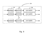
- Fig. 5 illustrates a transmitting RF chain group of the transmitting terminal 10.
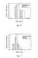
- Figs. 6 and 7 illustrate the probability that users are scheduled in the MIMO communication system of the present invention.
- Fig. 8 illustrates a duplexer group 130 for the transmitting terminal 10 of the present invention.
- Fig. 9 shows a receiving terminal 20 in the MIMO communication system of the present invention.
- Figs. 4 and 9 illustrate that the communication of the MIMO system is conducted in a manner of the layered space-time signal processing.
- Other technologies in signal processing method and apparutus, such as the space-time coding can also be adopted to process signals.
- the transmitting terminal 10 includes a MIMO signal processor 110, a MIMO scheduler 120, a duplexer group 130 and n T transmitting antennas.
- the MIMO scheduler 120 includes a receiving RF chain group 123, a MIMO receiving signal processor 122 and a scheduler 121, wherein, the receiving RF chain group 123 has receiving RF chains corresponding to the number of the transmitting antennas, which convert the received feedback signals into the corresponding code streams.
- the MIMO receiving signal processor 122 performs the layered space-time signal processing for the converted code streams to obtain the corresponding scheduling information.
- the scheduling information includes: the users to be scheduled, the data streams supported by each scheduled user, and the tranmitting antennas for tranmitting data of the scheduled users.
- the scheduler 121 controls the signal processing of the MIMO signal processor 110 by using the scheduling information.
- the MIMO signal processor 110 includes a user selector 111, a plurality of de-multiplexer 112 arranged in parallel, a MIMO transmitting signal processor 113, a transmitting RF chain group 114 and a transmitting antenna selector 115.
- the user selector 111 selects the nS users to be scheduled under the control of the scheduling information and outputs the corresponding user data.
- nS is less than or equal to the number of the transmitting antennas at the transmitting terminal 10.
- nS de-multiplexers 112 are selected to perform the distributing processing on the user data of nS users to be scheduled, i.e., the user data of the nS users to be scheduled are divided into L code streams and outputted, wherein the maximum value of L equals to n T , the number of transmitting antennas.
- L code streams outputted from the de-multiplexers 112 are processed by the MIMO transmitting signal processor 113 as L different layers with the manner of the layered space-time signal processing.
- the transmitting RF chain group 114 converts L code streams processed by the layered space-time signal processing into the corresponding L RF signals.
- the transmitting antenna selector 115 selects L scheduled transmitting antennas to transmit L RF signals outputted from the transmitting RF chain group 114 to L scheduled transmitting antennas through the duplexer group 130.
- L scheduled transmitting antennas tranmit the RF signals to the scheduled users.
- Fig. 5 further illustrates the concrete structure of the transmitting RF chain group 114, which includes L transmitting RF chains arranged in parallel.
- Each transmitting RF chain has a modulator 116, an upconverter 117, and a power amplifer 118 in series, and the power amplifier 118 can be a high power linear amplifier, wherein, L transmitting RF chains convert L code streams from the MIMO transmitting signal processor 113 into the corresponding RF signals, respectively.
- the value of said L is set according to the design of the system, which will be described later.
- the maximum probability is to schedule 2 users, the next is 3, the least is 1 or 4, and other probabilities are nearly zero. Therefore, the value of L can be set as 3 or further as 4 to decrease the scheduling loss of the system.
- the maximum probability is to schedule 3 users, the next is 2 or 4, the least is 5, and other probabilities are nearly zero. Therefore, the value of L can be set as 4 or further as 5 to decrease the scheduling loss of the system.
- the value of L can be modified according to the design of the system, and thus it is no need to set L as always n T , the number of the transmitting antennas. That is, the value of L is determined at the time of designing the system according to the scheduling conditions of the system, so that the number of the transmitting RF chain group is not always set as n T , which can cut down the cost of manufacuring the system.
- Fig. 8 illustrates a duplexer group at the transmitting terminal of the present invention, wherein, the duplexer group 130 has n T duplexers arranged in parallel and each duplexer connects with a corresponding transmitting antenna, the transmitting antenna selector 115 and the receiving RF chain group 123 as well.
- the Receiving Terminal 20 The Receiving Terminal 20
- the receiving terminal 20 has a receiving signal processor 210, a feedback information processor 220, a duplexer group 230 and n R receiving antennas.
- the receiving signal processor 210 includes a receiving RF chain group 211 and a MIMO receiving signal processor 212.
- the feedback information processor 220 includes a MIMO transmitting signal processor 221 and a transmitting RF chain group 222.
- the receiving RF chain group 211 has receiving RF chains arranged in parallel (not shown), and the number of receiving RF chains equals to that of the receiving antennas, n R .
- the receiving RF chains are used for resuming the received RF signals as the corresponding code streams and transmitting them to the MIMO receiving signal processor 212.
- the MIMO receiving signal processor 212 recovers the code streams as the original user data and outputs them.
- Fig. 10 illustrates that the scheduler 121 adaptively selects the users to be scheduled according to the feedback information. The following steps explain the scheduling process:
- the method of the present invention can also be applied to the occasion that the number of the receiving antennas is larger than that of the transmitting antennas.
- the calculation of the channel capacity and the disturbing factor is simplified but is consistent with the system.
- Fig. 11 illustrates the scheduling for the MIMO communication system of the present invention.
- the left part of Fig. 11 shows the simplified structure of the MIMO communication system, and the right part illustrates fading coefficients between the receiving antennas and the corresponding transmitting antennas.
- the scheduling system includes 1 transmitting terminal 10 and 2 users (the receiving terminals) A and B, wherein, the transmitting terminal 10 has three transmitting antennas 14A, 14B and 14C mounted on, and users A and B have receiving antennas 12A and 12B, respectively.
- the feedback information of user A will be:
- the feedback information of user B will be:
- the transmitting terminal 10 schedules users according to the above feedback information:
- the feedback information of user B is:
- the transmitting terminal 10 schedules users according to the above feedback information:
- the scheduling method of the present invention can schedule user B having the maximum channel gain, eg. 9, whereas the scheduling method of reference 2 can only obtain the channel capacity with 7. Therefore, the scheduling method of the present invention can provide the maximum channel capacity.
- Fig. 12 illustrates the scheduling for the MIMO communication system of the present invention.
- the left part of Fig. 12 illustrates the simplified structure of the MIMO communication system, while the right part shows fading coefficients between the receiving antennas and the corresponding transmitting antennas.
- same components are illustrated with same reference signs used in Fig.11.
- the scheduling system includes one transmitting terminal 10 and two users A and B, wherein, the transmitting terminal 10 has three transmitting antennas 14A, 14B and 14C mounted on, and users A and B have receiving antennas 12A and 12B, respectively.
- the feedback information of user A will be:
- the feedback information of user B will be:
- the transmitting terminal 10 schedules users according to the above feedback information:
- the feedback information of user B is:
- the transmitting terminal 10 schedules users according to the above feedback information:
- the present invention realizes this function by an adaptive method, whereas reference 2 obtains the result under the condition that it must be known that two users are scheduled in advance. Under other conditions that scheduling two users may not be the best result, and the scheduling method of the present invention can find out the optimal group adaptively while the scheduling method of reference 2 cannot conduct such function.
- the scheduling method of the present invention is better than that of reference 2 and can provide the maximum channel capacity adaptively.
- the channel is supposed as the normalized Complex Gaussian distribution.
- the channel capacity (the statistical mean value) increases as the users increase because the multiuser gain of the system increases with the increase of the number of users. Meanwhile, the channel capacity of the system increases as the total transmitting power of the transmitting terminal 10 P increases. It can be seen from the comparison of the three scheduling methods that the adaptive scheduling method of the present invention can obtain the maximum channel capacity of the system, even the numbers of transmitting antennas and receiving antennas as well as the transmitting power have been changed properly, the scheduling method of the present invention among three scheduling methods can also obtain the maximum channel capacity of the system.
- the channel capacity the statistical mean value
- the above description focuses on the centralized multi-antenna system, a system that the transmitting antennas are mounted on the transmitting terminal 10 placed in the centre of a cellular. Further, the adaptive scheduling method of the present invention can also be applied to the distributed antenna system.
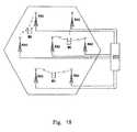
- Fig. 15 illustrates an adaptive distributed MIMO communication system of the present invention or an adaptive scheduling distributed multi-antenna system.
- Transmitting antennas are mounted on radio access units (RAU) similar to the base station, which are uniformly distributed in the whole cellular system.
- RAU radio access units
- locations that the RAUs are distributed in the whole cellular system can also be set in accordance with actual conditions so as to obtain the best performance of the system.
- the distributed multi-antenna system includes a plurality of radio access units (RAU), a base transceiver station (BTS), a plurality of users (MS) and connection links.
- Each radio access unit has at least one transmitting antenna mounted on for transceiving RF signals, and both the radio access units and the transmitting antennas are equivalent to the duplexer group 130 and transmitting antennas thereon, respectively.
- the radio access unit RAU includes at least one duplexer, and the number of the duplexers corresponds to the number of transmtting antennas connected thereto.
- the base transceiver station BTS is equivalent to the MIMO signal processor 110 and the MIMO scheduler 120 in Fig. 4.
- connection links connect the plurality of radio access units RAU with the base transceiver station BTS to transfer signals therebetween.
- the connection links can be wire links, such as the high-speed optical fibers.
- the radio access unit is required with a conversion function of photo/electric or electric/photo. Users represent the receiving terminals 20 as shown in Fig. 6.
- the operation of the distributed multi-anntenna system is similar to that of the centralized multi-antenna system mentioned above, and can decrease the system transmitting power and increase the data rate of the system relative to the centralized muti-antenna system.
- the MIMO communication system and its communication method have following advantages:
- the MIMO communication system of the present invention can perform an adaptive user scheduling so that the intelligentization of the system control and the stability of the communication are improved and the system capacity is always kept maximumly.
Landscapes
- Engineering & Computer Science (AREA)
- Computer Networks & Wireless Communication (AREA)
- Signal Processing (AREA)
- Physics & Mathematics (AREA)
- Mathematical Physics (AREA)
- Mobile Radio Communication Systems (AREA)
- Radio Transmission System (AREA)
Abstract
Description
- The present invention relates to a multiple input-multiple output (MIMO) system and a method of user scheduling, especially to an adaptive MIMO system and an adaptive user scheduling method.
- The future wireless communication system is required to support the extremely high speed data traffics, such as the videoconference, the video-on-demand and the interactive video game, etc.. As required in the ITU-R M1645, it should support up to 100Mbps for high mobility traffics and up to 1Gbps for low mobility or fixed wireless traffics. The data rate of one wireless channel equals to the product of its spectrum width and the spectrum efficiency of the adopted technology. In order to improve the data rate, the spectrum width of the channel and the spectrum efficiency of the adopted technology should be improved. However, since the frequency resource is limited, the communication speed cannot be raised by infinitely increasing the spectrum width. Improving the spectrum efficiency of the adopted technology is one optimal solution for resolving the problem. Recent reseach has discovered that the MIMO technology can be used to improve the spectrum efficiency.
- The so-called MIMO technology means that mutilple antennas are mounted at both the transmitting terminal and the receiving terminal in a communication system. The MIMO technology also includes that multiple antennas are mounted at either side, i.e., the single input-multiple output (SIMO) and the multiple input-single output (MISO). Different antennas are physically separated, and are generally regarded as introducing an additional signal domain-a space domain, into the communication system.
- In the MIMO system, two signal processing methods are generally adopted to improve the spectrum efficiency of channels:
- The first method is called the space-time coding (STC). It converts one original data stream into n T code streams by an encoder group and transmits them from different antennas (e.g., n T antennas) respectively. Wherein, each code stream is a different version of the original data stream and has the correlation with itself in time domain, and the correlation also exists between code streams. Thus, a better BER performance will be obtained by using these correlations at the receiving terminal having n R antennas, or, the spectrum efficiency will be improved by increasing the number of bits on each signal symbol when the BER performance is kept constantly. The gain that is obtained in the space domain by the space-time coding is called the diversity gain and the diversity gain provided by the MIMO system is n T × n R .
- The second signal processing method is called the layered space-time signal processing (LAST). It divides an original data stream into n T independent code streams and transmits each code steam from a different antenna, respectively. Each code stream is a part of the original data stream and there are no any correlation exists between these code steams. At the receiving terminal, each code stream transmitted from different antennas is decomposed by multimensional signal processing methods, such as, the maximum likelihood (ML), the minimum mean square error (MMSE), or the zero-forcing (ZF). Thus, n T indenpent channels are established between the receiving terminals and the transmitting terminals and the frequency efficiency is inceased by about n T times. A gain that is obtained at the space domain by the layered space-time signal processing is called the multiplexing gain. A MIMO system can provide a maximum multiplexing gain which equals to the minimum one of the numerals, n T and n R , i.e., min (n T , n R ).
- Research has discovered that in a single user point-to-point MIMO communication system, there is a tradeoff between the diversity gain and the multiplexing gain provided by the space domain: the more the diversity gain, the less the multiplexing gain, and vice versa.
- However, the modem communication systems are constructed almost based on a cellular structure, and the basic communication model thereof is that one base station in the cellular serves a plurality of users simultaneously, which leads to a problem of the multiple access. Traditional accessing methods include FDMA, TDMA and CDMA, which are all based on the circuit switch principle, i.e., each user is assigned with a fixed frequency width (for FDMA), a fixed time slot (for TDMA) or a fixed spread code (for CDMA).
- In GSM, for example, the base station assigns eight time slots of a frame to eight users in the manner of the fixed time slot assignment on a 200K channel. The method can ensure the time delay characteristic of communication traffics and fits the traffics sensitive to the time delay, such as the voice communication. But the disadvantage of the method is that the resources assignment is set regardless of the conditions of the wireless channels. However, conditions of wireless channels change greatly, the system will lose its performance if users are assigned with the channels which are just in a deep fading.
- The future communication system will mostly focus on data traffics and be not strict with the time delay. Then, the packet switch is acceptable for the multiple access. When conducting the packet switch, the base station is required to assign channels to different users in real time, which is called the user scheduling. Two basic user-scheduling methods are being used currently in the wireless communication system. One is the Round Robin scheduling, wherein, channels are assigned to all users in a manner of the round robin. Same as the circuit switch, the method can ensure the time delay characteristic and the justice for users but cannot improve the performance of the system. The other is the Maximum C/I scheduling. It can assign channels to users having the maximum C/I according to current channel-fading conditions, thereby, the system performance gets improved greatly. The gain that is obtained by the Maximum C/I scheduling is called the multiuser diversity.
- Research also discovers that in the conventional multiuser single input single output system (MuSISO system), the system performance can reach the maximum by assigning channels to users having the maximum C/I. But the result cannot be applied to the multiuser multi-antenna system-the multiuser MIMO system. While applied to a multiuser system, multiple antennas can provide not only the multiuser access-the spatial division multiple accesses (SDMA), but also the diversity gain and multiplexing gain. By using the spatial division multiple access, a user permited to be access is assigned with a certain spatial resource to create corresponding independent communication links, and the spatial resource of each user can be used to provide the diversity gain or the multiplexing gain. Research further shows that in case of multiple antennas, the system performance can reach the maximum only when channels are simultaneously assigned to one or more users. The above discovery, however, is only a guidance for a theory and lacks an efficient optimal user scheduling method.
- For downlink of communication system, the spatial division multiple access can be performed by using methods of transmitting signal proccessings, such as the dirty paper coding (DPC) and the transmit beamforming (TBF), at base stations. But the method requires that transmitting terminals (base stations) know the precise fading coeffiecency of downward channels, which, however, is difficult to be realized in an actual system. Another method for performing the spatial division multiple accesses is by using the receiving signal processing. Concretely, the useful information is processed by using the method of the space coding or layered space-time signal processing at transmitting terminals and demodulated by interference elimination or signal detection at user terminals. Since the space-time coding and layered signal processing do not require the fading coefficiency of the downward channels and are therefore suitable for performing the spatial division multiple access of the downward channels.
- Further, it is discovered that, when using the space-time coding based multiuser system, the performance of multiuser scheduling systems is poorer than that of the single antenna system. Therefore, in the multiuser scheduling system, it is apt to adopt the layered space-time signal processing based multiple input-multiple output system for each user permited to access, i.e., the transmitting terminals find out a users group according to the limited channel feedback information and assign antennas to all users of the user group so as to transmit an independent code stream of each user from each antenna assigned to the user. When the number of receving antennas n R is larger than that of transmitting antennas n T at the transmitting terminals, each user can establish an independent interference-free channel for each transmitting antenna. And in such case, the assignment of each transmitting terminal does not interfere the assignment of other antennas. U. S. Pat. No. 6, 662, 024 discloses a user scheduling arithmetic of the multiuser multiple input-multiple output sytem at the precondition of n R ≥ n T . But when the number of receiving antennas is smaller than that of transmitting antennas, an independent interference-free channel cannot be established for each transmitting antenna according to the method disclosed in the patent and the method disclosed in US 6, 662, 024 thus cannot be used.
- Reference 1 (D. J. Mazzarese and W. A. Krzymien, [2003], "High throughput downlink cellular packet data access with multiple antennas and multiuser diversity") discloses a user scheduling method when n R = 1. It is supposed that the number of the scheduled users is always n T , so that all n T transmitting antennas can be assigned to n T users, respectively. However, the problem is that the optimal performance of the system cannot be ensured.
- Reference 2 (D. Aktas and H. E. Gamal, [2003], "Multiuser scheduling for MIMO wireless systems") deems that the number of the scheduled users should be a predetermined number L (1 ≤ L ≤ n T ), which requires to select L antennas from all n T transmitting antennas and assigns them to selected L users, respectively. The method is only efficient when the number L has been given since the value of L is not clear yet.
- Methods disclosed in
References - 1). They are the methods of scheduling fixed number of users and the number of scheduled users is supposed to be known;
- 2). Their arithmetics cannot ensure the scheduling of all the supposed scheduled users, which leads to a loss of the performance of the system;
- 3). Solutions are all given when n R =1, and no concrete arithmetic is given when n R > 1 due to the high complexity of the arithmetics.
- Therefore, those disclosed methods cannot provide the optimal user scheduling according to channel conditions, i.e., they cannot provide the maximum system capacity.
- One object of the present invention is to provide an adaptive MIMO communication system, which can provide the maximum channel capacity for the system by using an adaptive user scheduling.
- Another object of the present invention is to provide an adaptive user scheduling method for the MIMO communication system, which can provide the optimal user scheduling according to the current channel conditions.
- An MIMO communication system capable of adaptive user scheduling comprises: a transmitting terminal, configured to transmit data frames containing at least channel estimation signal and user data; and at least one receving terminal, configured to receive the data frames transmitted by the transmitting terminal, and produce corresponding feedback information as well as recover the user data. The the feedback information comprises an optimal transmitting antenna set dedicated to the receiving terminal, the achievable channel capacity by each antenna within the antenna set, and the degradation factors caused by each of other unselected antennas to each of the selected antennas. The transmitting terminal produces scheduling information based on the feedback information. After that, the scheduling information will be used to adaptively schedule the users. The scheduling information comprises the scheduled users, number of data streams supported by each scheduled user, and the corresponding transmitting antenna for each of the data streams.
- An adaptive user scheduling method for a MIMOcommunication system of the present invention comprises following steps:
- a). the receving terminal produces feedback information based on the channel fading condition between transmitted antennas and receiving antennas and feedbacks it to the transmitting terminal;
- b). the transmitting terminal receives the feedback information and produces scheduling information and adaptively schedules the users according to the obtained scheduling information,
- In said adaptive user scheduling method, the channel fading conditions can be obtained via channel estimation signal received by the receiving terminal.
- In said adaptive user scheduling method, the channel fading conditions can also be obtained via data frames received by the receiving antennas while the receiving terminal receives the data frames.
- The aforesaid step b) further comprises steps of:
- 1). initializing the set of scheduled users and set of assigned antennas as null set;
- 2). comparing channel capacities in the feedback information, and selecting a user having the maximum channel capacity, then adding the selected user to the set of scheduled users, and adding the transmitting antenna corresponding to the selected user to set of assigned antennas;
- 3). selecting a transmitting antenna with the least degradation factor for the user in the set of scheduled users, and finding out another user corresponding to the selected transmitting antenna and having the maximum channel capacity;
- 4). calculating the total capacity of the system when another user is added to the system, and
If the total capacity is increased, adding the user to the scheduled user set and adding the corresponding antenna to the assigned antenna set and proceeding step 3); if the total capacity is decreased, ending the scheduling process; - 5). scheduling users in the system according to the final scheduled users set and the assigned antennas set.
- Compared with the prior art, the MIMO coommuncation system and the scheduling method of the present invention have advantages shown below:
- Since information fed back from each receiving terminal is: an optimal transmitting antenna set dedicated to the receiving terminal, the achievable channel capacity by each antenna within the antenna set, and the degradation factors caused by each of other unselected antennas to each of the selected antennas. The complexity of arithmetic for selecting transmitting antennas can be simplified without the awareness of the number of the scheduled users, and the absolute channel capacities is not affected by the number of the final scheduled users;
- The number of the scheduled users at the transmitting terminal dependends on the current conditions of the channels without a predetermination.
- Therefore, the MIMO communication system can perform an adaptive user scheduling so that the intelligentization of the system control and the stability of the communication are achieved and the system capacity is always kept maximumly.
- The present invention will become further apparent from the accompanying drawings:
- Fig. 1 is a block diagram showing a communication system of the present invention;
- Fig. 2 is a flow chart showing an adaptive user scheduling in the communication system illustrated in Fig. 1;
- Fig. 3 is a sketch drawing showing a frame structure used in the MIMO communication system of the present invention;
- Fig. 4 is a sketch drawing showing a transmitting terminal in the MIMO communication system of the present invention;
- Fig. 5 is a sketch drawing showing a transmitting RF chain group at the transmitting terminal;
- Fig. 6 is a sketch drawing showing the probability that users are scheduled in the MIMO communication system of the present invention;
- Fig. 7 is another sketch drawing showing the probability that users are scheduled in the MIMO communication system of the present invention;
- Fig. 8 is a sketch drawing showing a duplexer group at the transmitting terminal of the present invention;
- Fig. 9 is a sketch drawing showing a receiving terminal in the MIMO communication system of the present invention;
- Fig. 10 is a flow chart showing that a scheduler adaptively selects users to be scheduled according to the feedback information;
- Fig. 11 is a sketch drawing showing the scheduling of the MIMO communication system of the present invention;
- Fig. 12 is another sketch drawing showing the scheduling of the MIMO communication system of the present invention;
- Fig. 13 is a drawing showing the comparison of the performances of three different scheduling methods under the actual channel conditions;
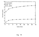
- Fig. 14 is a sketch drawing showing the performance of the MIMO communication system of the present invention when each receiving terminal has a plurality of receiving antennas;
- Fig. 15 is a sketch drawing showing an adaptive distributed MIMO communication system of the present invention.
- The present invention will be described in conjunction with the aforesaid drawings.
- Fig. 1 illustrates a MIMO communication system of the present invention, comprising: a transmitting terminal 10 (a base station) and a plurality of receiving terminals 20 (users). Fig. 2 is a flow chart showing an adaptive user scheduling for the communication system illustrated in Fig. 1. Fig. 3 is a sketch drawing illustrating a frame structure adopted in MIMO communication system of the present invention.
- As shown in Figures 1 to 3, the transmitting
terminal 10 has aMIMO signal processor 110, aMIMO scheduler 120, aduplexer group 130 and n T transmitting antennas. Each receivingterminal 20 has a receivingsignal processor 210, afeedback information processor 220, aduplexer group 230 and n R receiving antennas. The number of receiving antennas at each receivingterminal 20 can be different. The frame structure maybe simply explained as including a time slot for channel estimation, a time slot for channel information feedback and a time slot for data transmssion. Other time slots can be set as desired by the system. - As shown in Fig. 3, the transmitting
terminal 10 transmits the channel estimation signal to the receivingterminal 20 from n T transmitting antennas through theduplexer group 130 before it transmits data signal. - It is supposed that the channel estimation signal transmitted by the transmitting
terminal 10 is an n T dimensions complex numbers vector x ∈ C n T and the signal received by each receivingterminal 20 is an n R dimensions complex numbers vector y k ∈ C nR , and an n R × n T dimensions channel-fading matrix exists between the transmittingterminal 10 and the receivingterminal 20, as expressed in equation [1]:
wherein,
terminal 10 and the jth receiving antenna at the receiving terminal, and k denotes the kth user. - So the transfer function of the system can be expressed as equation [2]:

wherein, µ k ∈ C nT denotes an n R dimensions complex numbers vector indicating the white noise of the receivingterminal 20. - Each receiving
terminal 20 knows the actual channel-fading matrix H k and processes it via the receivingsignal processor 210 so as to obtain the following information: - 1). a transmitting antenna set AnI k selected from all of the n T transmitting antennas for the receiving
terminal 20 has the best performance. The number of the transmitting antennas in the selected transmitting antenna set AnI k equals to the number of the receiving antennas at the receivingterminal 20. - 2). the channel capacity R AnI
k provided to the receivingterminal 20 by each antenna of the transmitting antenna set AnI k is calculated by the equation [3]:
wherein, I nkR represents an n R level positive definite matrix and p represents a power.
The channel capacity R AnIk provided to the receivingterminal 20 by each antenna of the transmitting antenna set AnI k is then obtained. The calculating method for obtaining R AnIk is optional and is not limited to the one mentioned above. - 3). the degradation factors Df caused by each of other unselected antennas of the n T transmitting antennas to each of the selected antennas of the selected antenna set AnI k , is calculated by the receiving
signal processor 210, as expressed in equation [4]:
- The receiving
signal processor 210 delivers the above processed information as the feedback information to thefeedback information processor 220. The feedback information includes the optimal transmitting antenna set AnI k dedicated to the receiving terminal, the achievable channel capacity by each antenna within the antenna set AnI k , and the degradation factors Df k,i caused by each of other unselected antennas of the n T transmitting antennas to each of the selected antennas of the selected antenna set AnI k . - The
feedback information processor 220 processes the received user information and converts it into feedback signals (RF signals) suitable for the MIMO communication system. The feedback signals are transmitted from the antennas at the receivingterminal 20 and fed back to the transmittingterminal 10 through feedback channels. - The transmitting
terminal 10 receives the feedback signals and delivers them to theMIMO scheduler 120. TheMIMO scheduler 120 produces scheduling information according to the feedback signals and controls operations of theMIMO signal processor 110 using the produced scheduling information to make the MIMO communication system in the scheduling state of the optimal system capacity. That is, the optimal user scheduling is performed using the scheduling information. The scheduling information includes at least the scheduled users, number of data streams supported by each scheduled user, and the corresponding transmitting antenna for each of the data streams. - Further, after the scheduled users and the selected transmitting antennas are determined, the
MIMO signal processor 110 processes data of the scheduled users and transmits the processed data from the selected transmitting antennas to the corresponding scheduled users. - Thus, the MIMO communication system has advantages as follows:
- 1). At each receiving
terminal 20, the number of the transmitting antennas assigned thereto can be equal to the number of its receiving antennas as required; - 2). Information fed back from each receiving
terminal 20 is: an antenna set having the best performance, the absolute channel capacities provided by each of the selected antennas, and the degradation factors caused by each of the unselected antennas to each of the selected antennas. It can simplify the complexity of the arithmetic for selecting transmitting antennas without the awareness of the number of the scheduled users, and the absolute channel capacities will not be affected by the number of the final scheduled users; - 3). At the transmitting
terminal 10, the number of the scheduled users dependends on the current conditions of the channels without a predetermination. - Therefore, the MIMO communication system can perform an adaptive user scheduling, so that the intelligentization of system control and the stability of the communication are improved and the system capacity is always kept maximumly.
- The above method for obtaining the channel fading conditions is performed by using the channel estimation signal (i.e., the pilot signal). Accroding to the method, the channel estimation signal is inserted into the data frame, and the receiving
terminal 20 obtains the channel-fading conditions between the transmittingterminal 10 and the receivingterminal 20, and the receivingsignal processor 210 processes the channel fading conditions to obtain the user feedback information. - In the present invention, the channel-fading conditions can also be obtained by using the Blind Channel Estimation, i.e., the time slot for channel estimation is not set in the data frame. The receiving
terminal 20 obtains the channel-fading conditions via the Blind Channel Estimation after receiving data transmitted from the transmittingterminal 10, and the receivingsignal processor 210 processes the channel-fading conditions to obtain the feedback information, thereby avoiding the waste of the frequency resource caused by the insertion of the pilot signal for purpose of channel estimation. - Fig. 4 illustrates a transmitting
terminal 10 in the MIMO communication system of the present invention. Fig. 5 illustrates a transmitting RF chain group of the transmittingterminal 10. Figs. 6 and 7 illustrate the probability that users are scheduled in the MIMO communication system of the present invention. Fig. 8 illustrates aduplexer group 130 for the transmittingterminal 10 of the present invention. Fig. 9 shows a receivingterminal 20 in the MIMO communication system of the present invention. Figs. 4 and 9 illustrate that the communication of the MIMO system is conducted in a manner of the layered space-time signal processing. Other technologies in signal processing method and apparutus, such as the space-time coding, can also be adopted to process signals. - In Fig. 4, the transmitting
terminal 10 includes aMIMO signal processor 110, aMIMO scheduler 120, aduplexer group 130 and n T transmitting antennas. - The
MIMO scheduler 120 includes a receivingRF chain group 123, a MIMO receivingsignal processor 122 and ascheduler 121, wherein, the receivingRF chain group 123 has receiving RF chains corresponding to the number of the transmitting antennas, which convert the received feedback signals into the corresponding code streams. The MIMOreceiving signal processor 122 performs the layered space-time signal processing for the converted code streams to obtain the corresponding scheduling information. The scheduling information includes: the users to be scheduled, the data streams supported by each scheduled user, and the tranmitting antennas for tranmitting data of the scheduled users. Thescheduler 121 controls the signal processing of theMIMO signal processor 110 by using the scheduling information. - The
MIMO signal processor 110 includes auser selector 111, a plurality ofde-multiplexer 112 arranged in parallel, a MIMO transmittingsignal processor 113, a transmittingRF chain group 114 and a transmittingantenna selector 115. - The
user selector 111 selects the nS users to be scheduled under the control of the scheduling information and outputs the corresponding user data. Here, nS is less than or equal to the number of the transmitting antennas at the transmittingterminal 10. - Under the control of the scheduling information, nS de-multiplexers 112 are selected to perform the distributing processing on the user data of nS users to be scheduled, i.e., the user data of the nS users to be scheduled are divided into L code streams and outputted, wherein the maximum value of L equals to n T , the number of transmitting antennas.
- Then, L code streams outputted from the
de-multiplexers 112 are processed by the MIMO transmittingsignal processor 113 as L different layers with the manner of the layered space-time signal processing. - The transmitting
RF chain group 114 converts L code streams processed by the layered space-time signal processing into the corresponding L RF signals. - Under the control of the scheduling information, the transmitting
antenna selector 115 selects L scheduled transmitting antennas to transmit L RF signals outputted from the transmittingRF chain group 114 to L scheduled transmitting antennas through theduplexer group 130. - Finally, L scheduled transmitting antennas tranmit the RF signals to the scheduled users.
- Fig. 5 further illustrates the concrete structure of the transmitting
RF chain group 114, which includes L transmitting RF chains arranged in parallel. Each transmitting RF chain has amodulator 116, anupconverter 117, and apower amplifer 118 in series, and thepower amplifier 118 can be a high power linear amplifier, wherein, L transmitting RF chains convert L code streams from the MIMO transmittingsignal processor 113 into the corresponding RF signals, respectively. - The value of said L is set according to the design of the system, which will be described later.
- Fig. 6 illustrates the probability that users are scheduled in the MIMO communication system of the present invention, wherein, the transmitting
terminal 10 has 4 transmitting antennas and the number of the receiving terminal 20 (a user) is K=32, each receivingterminal 20 has 1 receiving antenna. When the total power of the transmittingterminal 10 is P=1 and P=10, in the MIMO communication system, the maximum probability is to schedule 2 users, the next is 3, the least is 1 or 4, and other probabilities are nearly zero. Therefore, the value of L can be set as 3 or further as 4 to decrease the scheduling loss of the system. - Similarly, Fig. 7 also illustrates the probability that users are scheduled in the MIMO communication system of the present invention, wherein, the transmitting
terminal 10 has 8 transmitting antennas, the number of the receiving terminal 20 (a user) is K=32, each receivingterminal 20 has 1 receiving antenna. When the total power of the transmittingterminal 10 is P=1 and P=10, in the MIMO communication system, the maximum probability is to schedule 3 users, the next is 2 or 4, the least is 5, and other probabilities are nearly zero. Therefore, the value of L can be set as 4 or further as 5 to decrease the scheduling loss of the system. - It can be seen from the above description that the value of L can be modified according to the design of the system, and thus it is no need to set L as always n T , the number of the transmitting antennas. That is, the value of L is determined at the time of designing the system according to the scheduling conditions of the system, so that the number of the transmitting RF chain group is not always set as n T , which can cut down the cost of manufacuring the system.
- Fig. 8 illustrates a duplexer group at the transmitting terminal of the present invention, wherein, the
duplexer group 130 has n T duplexers arranged in parallel and each duplexer connects with a corresponding transmitting antenna, the transmittingantenna selector 115 and the receivingRF chain group 123 as well. - To simplify the description, only the receiving
terminal 20 for one scheduled user is shown here. - In Fig. 9, the receiving
terminal 20 has a receivingsignal processor 210, afeedback information processor 220, aduplexer group 230 and n R receiving antennas. - The receiving
signal processor 210 includes a receivingRF chain group 211 and a MIMO receivingsignal processor 212. Thefeedback information processor 220 includes a MIMO transmittingsignal processor 221 and a transmittingRF chain group 222. - The receiving
RF chain group 211 has receiving RF chains arranged in parallel (not shown), and the number of receiving RF chains equals to that of the receiving antennas, n R . The receiving RF chains are used for resuming the received RF signals as the corresponding code streams and transmitting them to the MIMO receivingsignal processor 212. - The MIMO
receiving signal processor 212 recovers the code streams as the original user data and outputs them. - The scheduling process of the present invention will be more clearly described with reference to Fig. 10.
- Fig. 10 illustrates that the
scheduler 121 adaptively selects the users to be scheduled according to the feedback information. The following steps explain the scheduling process: - 1). initializing the set of scheduled users SU and set of assigned antennas SA as null set;
- 2). comparing channel capacities R Anl
k in the feedback information, and selecting a user having the maximum channel capacity, then adding the selected user to the set of scheduled users SU, and adding the transmitting antenna corresponding to the selected user to set of assigned antennas SA; - 3). selecting a transmitting antenna with the least degradation factor for the user in the set of scheduled users, and finding out another user corresponding to the selected transmitting antenna and having the maximum channel capacity;
- 4). calculating the total capacity of the system when another user is added to the system, and
if the total capacity is increased, adding the user to the scheduled user set SU and adding the corresponding antenna to the assigned antenna set SA and proceeding step 3); if the total capacity is decreased, ending the scheduling process; - 5). controlling the
MIMO signal processor 110 according to the set of scheduled users SU and the set of assigned antennas SA, to divide data of the scheduled users into independent code streams and transmit them from the assigned transmitting antenna. - For a clear description of the advantages of the present invention, the method disclosed in
reference 2 is adopted here for a comparison. Sincereference 2 only provides one concrete arithmetic when the number of antennas of each receivingterminal 20 is n R =1 1 and the number of users to be scheduled is fixed (but it does not disclose the structure of the system). We suppose that the number of antennas of each receivingterminal 20 is n R = 1 and the number of the scheduled users is 2, which can be regard as the occasion that the number of the receiving antennas is less than that of the transmitting antennas. But such suppose is just for a better understanding of the present invention, and the method of the present invention can also be applied to the occasion that the number of the receiving antennas is larger than that of the transmitting antennas. In the meantime, for a concise explanation of the user scheduling, the calculation of the channel capacity and the disturbing factor is simplified but is consistent with the system. - Fig. 11 illustrates the scheduling for the MIMO communication system of the present invention. The left part of Fig. 11 shows the simplified structure of the MIMO communication system, and the right part illustrates fading coefficients between the receiving antennas and the corresponding transmitting antennas.
- As illustrated in Fig. 11, the scheduling system includes 1 transmitting
terminal terminal 10 has three transmittingantennas antennas - When the receiving
antennas antennas signal processors 212 calculate the fading coefficient between each receiving antenna and each transmitting antenna, wherein, the fading coefficients between the receivingantenna 12A of user A and the transmittingantennas 


antenna 12B of user B and the transmittingantennas 


- In
Reference 2 - According to the above fading coefficients, if the method of
reference 2 is adopted, the feedback information of user A will be: - 1). the transmitting antenna having the best performance for user A is the transmitting
antenna 14A, i.e., the best transmitting antenna is AnI 1 = {1}; - 2). the transmitting antenna having the worst performance for user A, i.e., the transmitting antenna having the minimum disturbance or channel gain for user A, is the transmitting
antenna 14B, marked with S 1 = {2}; and - 3). the signal-to-interference-plus-noise ratio of the best transmitting antenna to the worst transmitting antenna is:

- Also, the feedback information of user B will be:
- 1). the transmitting antenna having the best performance for user B is the transmitting
antenna 14B, i.e., the best transmitting antenna set is AnI 2 = {2}; - 2). the transmitting antenna having the worse performance for user B is the transmitting
antenna 14C, which is marked with S 2 = {3}; and - 3). the signal-to-interference-plus-noise ratio of the best transmitting antenna to the worst transmitting antenna is:

- Next, the transmitting
terminal 10 schedules users according to the above feedback information: - 1). to find out a user having the maximum signal-to-interference-plus-noise ratio. In such statement, the user is user A and the signal-to-interference-plus-noise ratio is 7;
- 2). to find out another user, and the best antenna for it must be the worst antenna for user A, i.e., the transmitting
antenna 14B. User B is thus found. Then, a judgement is made on whether the worst antenna for user B is the best one for user A: if not, the introduction of the best antenna for user B will disturb user A, and user B cannot be scheduled; if yes, user B will be scheduled. Hence, the worst antenna for user B-thetransmitting antenna 14B, is not the best antenna for user A-the transmittingantenna 14 A but the transmittingantenna 14C, so user B cannot be scheduled. Meanwhile, since the feedback information includes AnI 1, S 1, AnI 2, S 2, SINR 1 and SINR 2, the conditions of channel gain of the system cannot be determined after user B is added to the system, according to these information. Therefore, user B cannot be scheduled; and - 3). As a result, the system can only schedule one user, user A, and the transmitting
antenna 14A is assigned to user A, and the channel gain is 7. - From the results of the channel-fading coefficient, it can be known that the feedback information of user A is:
- 1). the transmitting antenna having the best performance for user A is the transmitting
antenna 14A, i.e., the best transmitting antenna set is AnI 1 = {1}; - 2). the channel capacity that the antenna pair of 12A and 14A gives to user A, is

- 3). the fading factors of each antenna pair formed between the receiving
antenna 12A and the unselected transmittingantennas - The feedback information of user B is:
- 1). the transmitting antenna having the best performance for user B is the transmitting
antenna 14B, i.e., the best transmitting antenna set is AnI 2 = {2}; - 2). the channel capacity that the
antenna pair 
- 3). the fading factors of each antenna pair formed between the receiving
antenna 12B and theunselected transmitting antennas - Next, the transmitting
terminal 10 schedules users according to the above feedback information: - 1). to find out a user having the maximum channel capacity. User B is found with the
channel capacity 9, and the best transmitting antenna is determined as the transmittingantenna 14B; - 2). to find out another user according to the found transmitting antenna14B, the best antenna for another user must be the worst antenna for user B, i.e., the transmitting
antenna 14C. Since the transmittingantenna 14C is not the best antenna for user A, user A cannot be scheduled; and - 3). As a result, the system can schedule user B that can provide the maximum channel capacity, and the transmitting
antenna 14B is assigned to user B, then the total channel gain is 9. - It can be seen from the comparison between the scheduling methods of
reference 2 and the present invention that the scheduling method of the present invention can schedule user B having the maximum channel gain, eg. 9, whereas the scheduling method ofreference 2 can only obtain the channel capacity with 7. Therefore, the scheduling method of the present invention can provide the maximum channel capacity. - Fig. 12 illustrates the scheduling for the MIMO communication system of the present invention. The left part of Fig. 12 illustrates the simplified structure of the MIMO communication system, while the right part shows fading coefficients between the receiving antennas and the corresponding transmitting antennas. For the convienience of describing the present invention, same components are illustrated with same reference signs used in Fig.11.
- As illustrated in Fig. 12, the scheduling system includes one transmitting
terminal 10 and two users A and B, wherein, the transmittingterminal 10 has three transmittingantennas antennas - When the receiving
antennas antennas signal processors 212 calculate the fading coefficient between each receiving antenna and each transmitting antenna, wherein, the fading coefficients between the receivingantenna 12A of user A and the transmittingantennas 
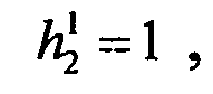

antenna 12B of user B and the transmittingantennas 
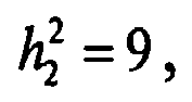

antenna 14A of user B exchanges with that of the transmittingantenna 14C of user B. - According to the above fading coefficients, if the method of
reference 2 is adopted, the feedback information of user A will be: - 1). the transmitting antenna having the best performance for user A is the transmitting
antenna 14A, i.e., the best transmitting antenna set is AnI 1 = {1}; - 2). the transmitting antenna having the worst performance for user A is the transmitting
antenna 14B, which is marked with S 1 = {2}; and - 3). the signal-to-interference-plus-noise ratio of the best transmitting antenna to the worst transmitting antenna is:

- Also, the feedback information of user B will be:
- 1). the transmitting antenna having the best performance for user B is the transmitting
antenna 14B, which is marked with AnI 2 = {2}; - 2). the transmitting antenna having the worse performance for user B is the transmitting
antenna 14A, which is marked with S 2 = {1}; and - 3). the signal-to-interference-plus-noise ratio of the best transmitting antenna to the worst transmitting antenna is:

- Next, the transmitting
terminal 10 schedules users according to the above feedback information: - 1). to find out a user having the maximum signal-to-interference-plus-noise ratio. In such statement, the user is user A and the signal-to-interference-plus-noise ratio is 7;
- 2). to find out another user, and the best antenna for it must be the worst antenna for user A, i.e., the transmitting
antenna 14B. User B is found. Then, a judgement is made on whether the worst antenna for user B is the best one for user A: if not, the introduction of the best antenna for user B will disturb user A, and user B cannot be scheduled; if yes, it needs to further determine whether the introduction of user B can increase the channel capacity. The channel gain of the system provided by user B is 2.25, so user B becomes a user to be scheduled too; and - 3). As a result, the system can schedule two users, user A and user B. The transmitting
antennas 14A is assigned to user A and the transmittingantennas 14B is assigned to user B. The channel gains are 7 and 2.25 respectivey and the total channel gain is 9.25. - From the result of the channel-fading coefficients, it can be known that the feedback information of user A is:
- 1). the transmitting antenna having the best performance for user A is the transmitting
antenna 14A, i.e., the best transmitting antenna set is AnI 1 = {1}; - 2). the channel capacity that the antenna pair of 12A and 14A gives to user A, is

- 3). the fading factors of each antenna pair formed between the receiving
antenna 12A and the unselected transmittingantennas - The feedback information of user B is:
- 1). the transmitting antenna having the best performance for user B is the transmitting
antenna 14B, i.e., the best transmitting antenna set is AnI 2 = {2}; - 2). the channel capacity that the antenna pair of 12B and 14B gives to user B, is

- 3). the fading factors of each antenna pair formed between the receiving
antenna 12B and theunselected antennas - Next, the transmitting
terminal 10 schedules users according to the above feedback information: - 1). to find out a user having the maximum channel capacity. User B is found with
channel capacity 9, and the best transmitting antenna is determined as the transmittingantenna 14B; - 2). to find out another user according to the found transmitting antenna14B, the best antenna for another user must be the worst antenna for user B, i.e., the transmitting
antenna 14C. Since the transmittingantenna 14C is the best antenna for user A, and determination needs to be made on whether user A can increase the channel capacity of the system. It can be seen from the result of scheduling user A that the total channel gain is 9/4 + 7/1 = 9.25, larger than 9, so user A can be scheduled; - 3). As a result, the system can schedule user A and user B. The transmitting
antenna 14A is assigned to user A, the transmittingantenna 14B is assigned to user B, and the total channel gain is 9.25. - It can be seen from the comparison between the scheduling methods of
reference 2 and the present invention that althrough the present invention andreference 2 can both schedule an optimal user group, the present invention realizes this function by an adaptive method, whereasreference 2 obtains the result under the condition that it must be known that two users are scheduled in advance. Under other conditions that scheduling two users may not be the best result, and the scheduling method of the present invention can find out the optimal group adaptively while the scheduling method ofreference 2 cannot conduct such function. - Therefore, the scheduling method of the present invention is better than that of
reference 2 and can provide the maximum channel capacity adaptively. - To further represent the advantages of the adaptive scheduling system and the adaptive scheduling method of the present invention, a comparison of the performances between three dfferent scheduling methods in the real channel conditions is shown in Fig. 13, wherein, the x-axis denotes the number of users and the y-axis denotes the channel capacity, the number of transmitting antennas of the transmitting
terminal 10 is 4, and each user has 1 receiving antenna and the total transmitting power of the transmittingterminal 10 is P=1 and P=10. The channel is supposed as the normalized Complex Gaussian distribution. - In Fig. 13, the channel capacity (the statistical mean value) increases as the users increase because the multiuser gain of the system increases with the increase of the number of users. Meanwhile, the channel capacity of the system increases as the total transmitting power of the transmitting terminal 10 P increases. It can be seen from the comparison of the three scheduling methods that the adaptive scheduling method of the present invention can obtain the maximum channel capacity of the system, even the numbers of transmitting antennas and receiving antennas as well as the transmitting power have been changed properly, the scheduling method of the present invention among three scheduling methods can also obtain the maximum channel capacity of the system.
- Fig. 14 illustrates the performance of the MIMO communication system of the present invention when each receiving terminal has a plurality of receiving antennas, wherein, the x-axis denotes the number of users and the y-axis denotes the channel capacity, the number of transmitting antennas of the transmitting
terminal 10 is 4 and each user has 2 receiving antennas and the total transmitting power of the transmittingterminal 10 is P=1 and P=10. It can be seen that the channel capacity (the statistical mean value) increases as users increase, and the channel capacity of the system increases with the increase of the total transmitting power P of the transmittingterminal 10, which further displays the advantages of the adaptive scheduling of the present invention. - The above description focuses on the centralized multi-antenna system, a system that the transmitting antennas are mounted on the transmitting
terminal 10 placed in the centre of a cellular. Further, the adaptive scheduling method of the present invention can also be applied to the distributed antenna system. - Fig. 15 illustrates an adaptive distributed MIMO communication system of the present invention or an adaptive scheduling distributed multi-antenna system. Transmitting antennas are mounted on radio access units (RAU) similar to the base station, which are uniformly distributed in the whole cellular system. Certainly, locations that the RAUs are distributed in the whole cellular system can also be set in accordance with actual conditions so as to obtain the best performance of the system.
- As shown in Fig. 15, the distributed multi-antenna system includes a plurality of radio access units (RAU), a base transceiver station (BTS), a plurality of users (MS) and connection links. Each radio access unit has at least one transmitting antenna mounted on for transceiving RF signals, and both the radio access units and the transmitting antennas are equivalent to the
duplexer group 130 and transmitting antennas thereon, respectively. The radio access unit RAU includes at least one duplexer, and the number of the duplexers corresponds to the number of transmtting antennas connected thereto. The base transceiver station BTS is equivalent to theMIMO signal processor 110 and theMIMO scheduler 120 in Fig. 4. The connection links connect the plurality of radio access units RAU with the base transceiver station BTS to transfer signals therebetween. The connection links can be wire links, such as the high-speed optical fibers. In the meantime, the radio access unit is required with a conversion function of photo/electric or electric/photo. Users represent the receivingterminals 20 as shown in Fig. 6. - Thus, the operation of the distributed multi-anntenna system is similar to that of the centralized multi-antenna system mentioned above, and can decrease the system transmitting power and increase the data rate of the system relative to the centralized muti-antenna system.
- In conclusion, the MIMO communication system and its communication method have following advantages:
- 1). Since information fed back from each receiving
terminal 20 is: an antenna set having the best performance, the absolute channel capacities by each antenna within the antenna set and the degradation factors caused by each of other unselected antennas to each of the selected antennas, the complexity of the arithmetic for selecting transmitting antennas can be simplified without the awareness of the number of the scheduled users, meanwhile the absolute channel capacity will not be affected by the number of the final scheduled users; - 2). the number of the scheduled users at the transmitting
terminal 10 dependends on the current conditions of the channels without a predetermination. - Therefore, the MIMO communication system of the present invention can perform an adaptive user scheduling so that the intelligentization of the system control and the stability of the communication are improved and the system capacity is always kept maximumly.
and the scheduling information comprises the scheduled users, number of data streams supported by each scheduled user, and the corresponding transmitting antenna for each of the data streams.
Claims (12)
- A MIMO communication system capable of adaptive user scheduling, comprising:a transmitting terminal (10), configured to transmit data frames containing at least channel estimation signal and user data;and at least one receving terminal (20), configured to receive the data frames transmitted by the transmitting terminal (10), and produce corresponding feedback information as well as recover the user data,wherein the feedback information comprises an optimal transmitting antenna set dedicated to the receiving terminal, the achievable channel capacity by each antenna within the antenna set, and the degradation factors caused by each of other unselected antennas to each of the selected antennas,
the transmitting terminal (10) produces scheduling information based on the feedback information, the scheduling information is used to adaptively schedule the users, and the scheduling information comprises the scheduled users, number of data streams supported by each scheduled user, and the corresponding transmitting antenna for each of the data streams. - A MIMO communication system capable of adaptive user scheduling as claimed in claim 1, characterized in that,
the transmitting terminal (10), comprising:a duplexer group (130) and corresponding mounted transmitting antennas, configured to transmit the data frame and receive the feedback information from the receiving terminal (20);a MIMO scheduler (120), configured to produce the scheduling information based on the feedback information; anda MIMO signal processor (110), configured to schedule the users according to the scheduling information, and transmit data of the scheduled users through the selected transmitting antennas,the receiving terminal (20), comprising:a duplexer group (230) and corresponding mounted receiving antennas, configured to recieve the data frame from the transmitting terminal (10) and transmit feedback information;a receiving signal processor (210), configured to produce user feedback information and recover the user data from the received data frame;a feedback information processor (220), configured to convert the user feedback information into the feedback signals. - A MIMO communication system capable of adaptive user scheduling as claimed in claim 2, characterized in that,
the MIMO scheduler (120), comprising:a receiving RF chain group (123), configured to convert the received RF signals to the corresponding code streams;a MIMO receiving signal processor (122), configured to produce the scheduling information through a layered space-time signal processing on the obtained code streams;a scheduler (121), configured to control the signal processing of the MIMO signal processor (110). - A MIMO communication system capable of adaptive user scheduling as claimed in claim 2, characterized in that,
the MIMO signal processor (110), comprising:a user selector (111), configured to select the users according to the scheduling information;a plurality of parallel de-multiplexer (112), configured to de-multiplex the user data of the scheduled users to generate a plurality of separated code streams;a MIMO transmitting signal processor (113), configured to conduct the layered space-time processing on the obtained plurality of separated code streams according to the scheduling information;a transmitting RF chain group (114), configured to convert the plurality of code streams processed by the MIMO transmitting signal processor (113) into the corresponding RF signals; anda transmitting antenna selector (115), configured to select transmitting antennas depending on the scheduling information. - A MIMO communication system capable of adaptive user scheduling as claimed in claim 4, characterized in that,
the transmitting RF chain group (114), comprising:A plurality of transmitting RF chains each of that is used to modulate one of the code streams generated by the MIMO transmitting signal processor (113) to the corresponding RF signal,wherein, each transmitting RF chain comprises a modulator (116), an upconverter (117), and a power amplifer (118) connected in serial. - A MIMO communication system capable of adaptive user scheduling as claimed in claim 2, characterized in that,
the receiving signal processor (210), comprising:a receiving RF chain group (211), configured to demodulate and convert the received RF signals to obtain the corresponding code streams;a MIMO receiving signal processor (212), configured to produce the corresponding user feedback information depending on the code streams and recover the user data, andthe feedback information processor (220), comprising:a MIMO transmitting signal processor (221), configured to convert the user feedback information into the feedback signals;a transmitting RF chain group (222), configured to convert the feedback signals into the corresponding RF signals. ' - A MIMO system capable of adaptive user scheduling as claimed in claim 5 or claim 6, characterized in that, the power amplifer (118) is a high power linear amplifier.
- A MIMO system capable of adaptive user scheduling as claimed in claim 7,
characterized in that, the number of the transmitting RF chains (114) is less than or equal to the number of the transmitting antennas. - An adaptive user scheduling method for MIMO communication system, comprising following steps:a). the receving terminal produces feedback information based on the channel fading condition between transmitted antennas and receiving antennas and feedbacks it to the transmitting terminal,b). the transmitting terminal receives the feedback information and produces scheduling information and adaptively schedules the users according to the obtained scheduling information,wherein, the the feedback information comprises an optimal transmitting antenna set dedicated to the receiving terminal, the achievable channel capacity by each antenna within the antenna set, and the degradation factors caused by each of other unselected antennas to each of the selected antennas,
and the scheduling information comprises the scheduled users, number of data streams supported by each scheduled user, and the corresponding transmitting antenna for each of the data streams. - An adaptive user scheduling method as claimed in claim 9, wherein, the channel fading conditions are obtained via channel estimation signal received by the receiving terminal.
- An adaptive user scheduling method as claimed in claim 9, wherein, the channel fading conditions are obtained via data frames received by the receiving antennas.
- An adaptive user scheduling method as claimed in any one of claims 9 to 11, wherein, step b) further comprising following steps:1). initializing the set of scheduled users and set of assigned antennas as null set;2). comparing channel capacities in the feedback information, and selecting a user having the maximum channel capacity, then adding the selected user to the set of scheduled users, and adding the transmitting antenna corresponding to the selected user to set of assigned antennas;3). selecting a transmitting antenna with the least degradation factor to the user in the set of scheduled users, and finding out another user corresponding to the selected transmitting antenna and having the maximum channel capacity;4). calculating the total capacity of the system when another user is added to the system, and
if the total capacity is increased, adding the user to the scheduled user set and adding the corresponding antenna to the assigned antenna set and proceeding step 3); if the total capacity is decreased, ending the scheduling process;5). scheduling users in the system according to the final scheduled users set and the assigned antennas set.
Applications Claiming Priority (1)
| Application Number | Priority Date | Filing Date | Title |
|---|---|---|---|
| CN200410104194.6A CN1797987B (en) | 2004-12-30 | 2004-12-30 | Communication system for self-adaptive scheduling MIMO, and method for self-adaptive scheduling users |
Publications (2)
| Publication Number | Publication Date |
|---|---|
| EP1677435A2 true EP1677435A2 (en) | 2006-07-05 |
| EP1677435A3 EP1677435A3 (en) | 2013-06-19 |
Family
ID=36120890
Family Applications (1)
| Application Number | Title | Priority Date | Filing Date |
|---|---|---|---|
| EP05026975.2A Withdrawn EP1677435A3 (en) | 2004-12-30 | 2005-12-09 | MIMO communication system and method capable of adaptive user scheduling |
Country Status (4)
| Country | Link |
|---|---|
| US (1) | US7688789B2 (en) |
| EP (1) | EP1677435A3 (en) |
| JP (1) | JP4813177B2 (en) |
| CN (1) | CN1797987B (en) |
Cited By (5)
| Publication number | Priority date | Publication date | Assignee | Title |
|---|---|---|---|---|
| EP1727298A2 (en) | 2005-05-24 | 2006-11-29 | NTT DoCoMo Inc. | A MIMO communication system based on random beamforming and its user scheduling method |
| WO2009094744A1 (en) * | 2008-02-01 | 2009-08-06 | Nortel Networks Limited | System and method for spatial multiplexing-based multiple antenna broadcast/multicast transmission |
| CN102573095A (en) * | 2012-02-10 | 2012-07-11 | 大唐移动通信设备有限公司 | User scheduling method and device |
| US8305949B2 (en) | 2006-09-11 | 2012-11-06 | Apple Inc. | System and method for spatial multiplexing-based OFDM broadcast/multicast transmission |
| EP2182663A4 (en) * | 2007-08-20 | 2014-06-25 | Alcatel Lucent | Low-information interactive multi-base station collaborative mimo and corresponding scheduling method and apparatus |
Families Citing this family (82)
| Publication number | Priority date | Publication date | Assignee | Title |
|---|---|---|---|---|
| KR100557158B1 (en) * | 2003-11-12 | 2006-03-03 | 삼성전자주식회사 | Apparatus and Method for Subcarrier Allocation in Mobile Communication System Using Orthogonal Frequency Division Multiplexing |
| FR2863122B1 (en) * | 2003-11-28 | 2006-04-28 | Thales Sa | METHOD AND APPARATUS FOR INCREASING THE CAPACITY OF NON-ETAL TRANSMISSION SYSTEMS |
| US10985811B2 (en) | 2004-04-02 | 2021-04-20 | Rearden, Llc | System and method for distributed antenna wireless communications |
| US10200094B2 (en) * | 2004-04-02 | 2019-02-05 | Rearden, Llc | Interference management, handoff, power control and link adaptation in distributed-input distributed-output (DIDO) communication systems |
| US10277290B2 (en) | 2004-04-02 | 2019-04-30 | Rearden, Llc | Systems and methods to exploit areas of coherence in wireless systems |
| US8542763B2 (en) * | 2004-04-02 | 2013-09-24 | Rearden, Llc | Systems and methods to coordinate transmissions in distributed wireless systems via user clustering |
| US11394436B2 (en) | 2004-04-02 | 2022-07-19 | Rearden, Llc | System and method for distributed antenna wireless communications |
| US8654815B1 (en) | 2004-04-02 | 2014-02-18 | Rearden, Llc | System and method for distributed antenna wireless communications |
| US11451275B2 (en) | 2004-04-02 | 2022-09-20 | Rearden, Llc | System and method for distributed antenna wireless communications |
| US9819403B2 (en) | 2004-04-02 | 2017-11-14 | Rearden, Llc | System and method for managing handoff of a client between different distributed-input-distributed-output (DIDO) networks based on detected velocity of the client |
| US9826537B2 (en) * | 2004-04-02 | 2017-11-21 | Rearden, Llc | System and method for managing inter-cluster handoff of clients which traverse multiple DIDO clusters |
| US11309943B2 (en) | 2004-04-02 | 2022-04-19 | Rearden, Llc | System and methods for planned evolution and obsolescence of multiuser spectrum |
| US10187133B2 (en) | 2004-04-02 | 2019-01-22 | Rearden, Llc | System and method for power control and antenna grouping in a distributed-input-distributed-output (DIDO) network |
| US9312929B2 (en) | 2004-04-02 | 2016-04-12 | Rearden, Llc | System and methods to compensate for Doppler effects in multi-user (MU) multiple antenna systems (MAS) |
| US10886979B2 (en) | 2004-04-02 | 2021-01-05 | Rearden, Llc | System and method for link adaptation in DIDO multicarrier systems |
| US10425134B2 (en) | 2004-04-02 | 2019-09-24 | Rearden, Llc | System and methods for planned evolution and obsolescence of multiuser spectrum |
| US10749582B2 (en) | 2004-04-02 | 2020-08-18 | Rearden, Llc | Systems and methods to coordinate transmissions in distributed wireless systems via user clustering |
| US9685997B2 (en) | 2007-08-20 | 2017-06-20 | Rearden, Llc | Systems and methods to enhance spatial diversity in distributed-input distributed-output wireless systems |
| US8724740B2 (en) * | 2005-03-11 | 2014-05-13 | Qualcomm Incorporated | Systems and methods for reducing uplink resources to provide channel performance feedback for adjustment of downlink MIMO channel data rates |
| US8634432B2 (en) * | 2005-05-06 | 2014-01-21 | Samsung Electronics Co., Ltd. | System and method for subcarrier allocation in a multicarrier wireless network |
| CN101336524B (en) * | 2006-02-02 | 2013-07-24 | 富士通株式会社 | Wireless transmission method, wireless transmitter and wireless receiver |
| WO2007121568A1 (en) * | 2006-04-21 | 2007-11-01 | Nortel Networks Limited | Method and system for closed loop multiple input/output antenna environments in wireless communication |
| US8331342B2 (en) * | 2006-04-28 | 2012-12-11 | Samsung Electronics Co., Ltd. | Apparatus and method for switching between single user and multi-user MIMO operation in a wireless network |
| KR101274871B1 (en) * | 2006-06-14 | 2013-06-17 | 삼성전자주식회사 | Method and apparatus for transceiving data in a multi antenna system of closed loop scheme |
| US8483145B2 (en) * | 2006-06-16 | 2013-07-09 | Telefonaktiebolaget Lm Ericsson (Publ) | Method for channel quality measures in a multiple antenna system |
| EP2055014B1 (en) * | 2006-08-25 | 2013-03-06 | Ikanos Technology Ltd. | Systems and methods for mimo precoding in an xdsl system |
| JP4734210B2 (en) * | 2006-10-04 | 2011-07-27 | 富士通株式会社 | Wireless communication method |
| CN101193094B (en) * | 2006-11-20 | 2011-10-19 | 电信科学技术研究院 | A method and system for sending broadcast/multicast service |
| US20080207258A1 (en) * | 2007-02-26 | 2008-08-28 | Broadcom Corporation, A California Corporation | Multimode transmitter with digital up conversion and methods for use therewith |
| US8054837B2 (en) * | 2007-04-30 | 2011-11-08 | Yim Tu Investments Ltd., Llc | Multiuser scheduling for MIMO broadcast channels with finite rate feedback |
| KR100895576B1 (en) * | 2007-05-11 | 2009-04-29 | 주식회사 팬택 | How to transmit data by selecting antenna in multi-input multi-output wireless LAN environment |
| US7649831B2 (en) * | 2007-05-30 | 2010-01-19 | Samsung Electronics Co., Ltd. | Multi-user MIMO feedback and transmission in a wireless communication system |
| US7983710B2 (en) * | 2007-05-31 | 2011-07-19 | Alcatel-Lucent Usa Inc. | Method of coordinated wireless downlink transmission |
| US8086272B2 (en) * | 2007-08-06 | 2011-12-27 | Mitsubishi Electric Research Laboratories, Inc. | Wireless networks incorporating antenna selection based on received sounding reference signals |
| US8989155B2 (en) | 2007-08-20 | 2015-03-24 | Rearden, Llc | Systems and methods for wireless backhaul in distributed-input distributed-output wireless systems |
| JP5387575B2 (en) * | 2007-08-31 | 2014-01-15 | 富士通株式会社 | Wireless communication system and wireless communication method |
| US8190165B2 (en) * | 2007-09-21 | 2012-05-29 | Future Wei Technologies, Inc. | System and method for utility-based scheduling for space division multiple access (SDMA) on an uplink of a wireless communications network |
| WO2009111832A1 (en) * | 2008-03-12 | 2009-09-17 | University Of Wollongong | A new type of gapless semiconductor material |
| EP2699052B1 (en) * | 2008-04-07 | 2018-12-05 | Telefonaktiebolaget LM Ericsson (publ) | A method of and a radio transmission system and radio access equipment for cellular wireless radio transmission |
| EP2131507B1 (en) * | 2008-06-06 | 2010-12-01 | NTT DoCoMo, Inc. | A user selection apparatus for a mobile communication system |
| EP2134003B1 (en) * | 2008-06-06 | 2011-12-28 | NTT DoCoMo, Inc. | A user selection apparatus and method for a mobile communication system |
| KR101001015B1 (en) * | 2008-09-25 | 2010-12-14 | 한국전자통신연구원 | Multi-antenna wireless communication system adaptively determines downlink transmission mode |
| KR101289944B1 (en) | 2008-12-12 | 2013-07-26 | 엘지전자 주식회사 | Method for channel estimation in very high throughput wireless local area network system and apparatus for the same |
| US8682326B2 (en) * | 2008-12-23 | 2014-03-25 | Telefonaktiebolaget Lm Ericsson (Publ) | Base station and method for vertical tilt antenna beam sweeping |
| AU2010210766A1 (en) | 2009-02-03 | 2011-09-15 | Corning Cable Systems Llc | Optical fiber-based distributed antenna systems, components, and related methods for monitoring and configuring thereof |
| US9673904B2 (en) | 2009-02-03 | 2017-06-06 | Corning Optical Communications LLC | Optical fiber-based distributed antenna systems, components, and related methods for calibration thereof |
| US8423068B2 (en) * | 2009-02-12 | 2013-04-16 | Clearwire Ip Holdings Llc | Quality of service based multi-antenna mode switching |
| US9125090B2 (en) * | 2009-02-27 | 2015-09-01 | At&T Mobility Ii Llc | Staggered channelization code allocation for multi-carrier networks |
| KR101589607B1 (en) * | 2009-03-02 | 2016-01-29 | 삼성전자주식회사 | Communication system having femto base station and communication terminal and communication method therefor |
| JP5391816B2 (en) | 2009-05-08 | 2014-01-15 | ソニー株式会社 | COMMUNICATION DEVICE AND COMMUNICATION METHOD, COMPUTER PROGRAM, AND COMMUNICATION SYSTEM |
| WO2010139353A1 (en) * | 2009-06-01 | 2010-12-09 | Telefonaktiebolaget L M Ericsson (Publ) | A node in a wireless communication system with different antenna diversity methods for uplink and downlink |
| US8743839B2 (en) * | 2009-07-01 | 2014-06-03 | Telefonaktiebolaget L M Ericsson (Publ) | Scheduling different types of receivers in a radio base station |
| JP4896196B2 (en) * | 2009-10-01 | 2012-03-14 | 株式会社エヌ・ティ・ティ・ドコモ | Cooperative transmission method, cooperative transmission system, aggregation station, and radio base station |
| US8280259B2 (en) | 2009-11-13 | 2012-10-02 | Corning Cable Systems Llc | Radio-over-fiber (RoF) system for protocol-independent wired and/or wireless communication |
| US8976770B2 (en) * | 2010-07-27 | 2015-03-10 | Lg Electronics Inc. | Method and device whereby base station allocates nodes to terminal in a semi-static fashion in multi-node system |
| US9252874B2 (en) | 2010-10-13 | 2016-02-02 | Ccs Technology, Inc | Power management for remote antenna units in distributed antenna systems |
| WO2012148940A1 (en) | 2011-04-29 | 2012-11-01 | Corning Cable Systems Llc | Systems, methods, and devices for increasing radio frequency (rf) power in distributed antenna systems |
| CN103548290B (en) * | 2011-04-29 | 2016-08-31 | 康宁光缆系统有限责任公司 | Judge the communication propagation delays in distributing antenna system and associated component, System and method for |
| CN102882662B (en) * | 2011-07-15 | 2014-12-10 | 华为技术有限公司 | Link Adaptive Feedback Method and Device |
| US9031033B2 (en) * | 2011-09-27 | 2015-05-12 | Apple Inc. | Wireless radio access network control channel capacity management |
| EP2842245A1 (en) | 2012-04-25 | 2015-03-04 | Corning Optical Communications LLC | Distributed antenna system architectures |
| US9455784B2 (en) | 2012-10-31 | 2016-09-27 | Corning Optical Communications Wireless Ltd | Deployable wireless infrastructures and methods of deploying wireless infrastructures |
| US11190947B2 (en) | 2014-04-16 | 2021-11-30 | Rearden, Llc | Systems and methods for concurrent spectrum usage within actively used spectrum |
| US11189917B2 (en) | 2014-04-16 | 2021-11-30 | Rearden, Llc | Systems and methods for distributing radioheads |
| US10194346B2 (en) | 2012-11-26 | 2019-01-29 | Rearden, Llc | Systems and methods for exploiting inter-cell multiplexing gain in wireless cellular systems via distributed input distributed output technology |
| US11050468B2 (en) | 2014-04-16 | 2021-06-29 | Rearden, Llc | Systems and methods for mitigating interference within actively used spectrum |
| CN103095351B (en) * | 2013-01-17 | 2015-05-27 | 西安电子科技大学 | Multi-input and multi-output system based on single carrier and full duplex |
| US9923657B2 (en) | 2013-03-12 | 2018-03-20 | Rearden, Llc | Systems and methods for exploiting inter-cell multiplexing gain in wireless cellular systems via distributed input distributed output technology |
| US10164698B2 (en) | 2013-03-12 | 2018-12-25 | Rearden, Llc | Systems and methods for exploiting inter-cell multiplexing gain in wireless cellular systems via distributed input distributed output technology |
| US10488535B2 (en) | 2013-03-12 | 2019-11-26 | Rearden, Llc | Apparatus and method for capturing still images and video using diffraction coded imaging techniques |
| US9973246B2 (en) | 2013-03-12 | 2018-05-15 | Rearden, Llc | Systems and methods for exploiting inter-cell multiplexing gain in wireless cellular systems via distributed input distributed output technology |
| US10547358B2 (en) | 2013-03-15 | 2020-01-28 | Rearden, Llc | Systems and methods for radio frequency calibration exploiting channel reciprocity in distributed input distributed output wireless communications |
| CN104509051B (en) * | 2013-06-27 | 2017-11-17 | 华为技术有限公司 | Channel Estimation Method and Receiver |
| JP6342618B2 (en) * | 2013-06-28 | 2018-06-13 | 株式会社Nttドコモ | Wireless base station, user terminal, and wireless communication method |
| CN103475107A (en) * | 2013-08-30 | 2013-12-25 | 成都远晟科技有限公司 | Wireless charging method and wireless charging transmitting antenna |
| FR3011704A1 (en) * | 2013-10-07 | 2015-04-10 | Orange | METHOD FOR IMPLEMENTING A COMMUNICATION SESSION BETWEEN A PLURALITY OF TERMINALS |
| US11290162B2 (en) | 2014-04-16 | 2022-03-29 | Rearden, Llc | Systems and methods for mitigating interference within actively used spectrum |
| CN104080188B (en) * | 2014-06-27 | 2017-07-14 | 中国科学院计算技术研究所 | Multi-user's Multiinputoutput wireless local network user dispatching method and system |
| US9681313B2 (en) | 2015-04-15 | 2017-06-13 | Corning Optical Communications Wireless Ltd | Optimizing remote antenna unit performance using an alternative data channel |
| US9948349B2 (en) | 2015-07-17 | 2018-04-17 | Corning Optical Communications Wireless Ltd | IOT automation and data collection system |
| CN105933104A (en) * | 2016-07-04 | 2016-09-07 | 重庆邮电大学 | Multi-user difference chaotic communication system based on Walsh codes |
| CN111049561A (en) * | 2019-11-01 | 2020-04-21 | 濠暻科技(深圳)有限公司 | Adaptive scheduling method for broadband electrically-tuned antenna of LTE (Long term evolution) system |
Family Cites Families (8)
| Publication number | Priority date | Publication date | Assignee | Title |
|---|---|---|---|---|
| US6662024B2 (en) * | 2001-05-16 | 2003-12-09 | Qualcomm Incorporated | Method and apparatus for allocating downlink resources in a multiple-input multiple-output (MIMO) communication system |
| US7072413B2 (en) * | 2001-05-17 | 2006-07-04 | Qualcomm, Incorporated | Method and apparatus for processing data for transmission in a multi-channel communication system using selective channel inversion |
| US7020110B2 (en) * | 2002-01-08 | 2006-03-28 | Qualcomm Incorporated | Resource allocation for MIMO-OFDM communication systems |
| US7412212B2 (en) * | 2002-10-07 | 2008-08-12 | Nokia Corporation | Communication system |
| US8208364B2 (en) * | 2002-10-25 | 2012-06-26 | Qualcomm Incorporated | MIMO system with multiple spatial multiplexing modes |
| KR20120024992A (en) * | 2003-04-23 | 2012-03-14 | 콸콤 인코포레이티드 | Methods and apparatus of enhancing performance in wireless communication systems |
| JP2007518346A (en) * | 2004-01-20 | 2007-07-05 | エルジー エレクトロニクス インコーポレイティド | Signal transmission / reception method in MIMO system |
| US7469491B2 (en) * | 2004-01-27 | 2008-12-30 | Crestcom, Inc. | Transmitter predistortion circuit and method therefor |
-
2004
- 2004-12-30 CN CN200410104194.6A patent/CN1797987B/en not_active Expired - Fee Related
-
2005
- 2005-12-09 EP EP05026975.2A patent/EP1677435A3/en not_active Withdrawn
- 2005-12-28 JP JP2005378884A patent/JP4813177B2/en not_active Expired - Fee Related
- 2005-12-30 US US11/322,615 patent/US7688789B2/en not_active Expired - Fee Related
Cited By (9)
| Publication number | Priority date | Publication date | Assignee | Title |
|---|---|---|---|---|
| EP1727298A2 (en) | 2005-05-24 | 2006-11-29 | NTT DoCoMo Inc. | A MIMO communication system based on random beamforming and its user scheduling method |
| EP1727298A3 (en) * | 2005-05-24 | 2012-06-13 | NTT DoCoMo, Inc. | A MIMO communication system based on random beamforming and its user scheduling method |
| US8305949B2 (en) | 2006-09-11 | 2012-11-06 | Apple Inc. | System and method for spatial multiplexing-based OFDM broadcast/multicast transmission |
| EP2182663A4 (en) * | 2007-08-20 | 2014-06-25 | Alcatel Lucent | Low-information interactive multi-base station collaborative mimo and corresponding scheduling method and apparatus |
| US8867477B2 (en) | 2007-08-20 | 2014-10-21 | Alcatel Lucent | Cooperative MIMO among base stations with low information interaction, a method and apparatus for scheduling the same |
| WO2009094744A1 (en) * | 2008-02-01 | 2009-08-06 | Nortel Networks Limited | System and method for spatial multiplexing-based multiple antenna broadcast/multicast transmission |
| US8929325B2 (en) | 2008-02-01 | 2015-01-06 | Apple Inc. | System and method for spatial multiplexing-based multiple antenna broadcast/multicast transmission |
| CN102573095A (en) * | 2012-02-10 | 2012-07-11 | 大唐移动通信设备有限公司 | User scheduling method and device |
| CN102573095B (en) * | 2012-02-10 | 2014-08-06 | 大唐移动通信设备有限公司 | User scheduling method and device |
Also Published As
| Publication number | Publication date |
|---|---|
| JP2006191620A (en) | 2006-07-20 |
| US20060146755A1 (en) | 2006-07-06 |
| CN1797987A (en) | 2006-07-05 |
| EP1677435A3 (en) | 2013-06-19 |
| CN1797987B (en) | 2011-02-16 |
| US7688789B2 (en) | 2010-03-30 |
| JP4813177B2 (en) | 2011-11-09 |
Similar Documents
| Publication | Publication Date | Title |
|---|---|---|
| US7688789B2 (en) | MIMO communication system and method capable of adaptive user scheduling | |
| KR100575993B1 (en) | Scheduling method and apparatus for multi-user in mobile communication system using multiple transmit / receive antenna | |
| EP2119038B1 (en) | Methods and systems for combined precoding and cyclic delay diversity | |
| US8306089B2 (en) | Precoding technique for multiuser MIMO based on eigenmode selection and MMSE | |
| US9923617B2 (en) | Communication channel optimization systems and methods in multi-user communication systems | |
| KR100876797B1 (en) | Beamforming apparatus and method in a multi-antenna system | |
| EP1386421B1 (en) | Radio communication system | |
| EP1727298A2 (en) | A MIMO communication system based on random beamforming and its user scheduling method | |
| KR100754660B1 (en) | Adaptive Modulation / Coded Channel Assignment System and Method in Communication Systems | |
| US8774302B2 (en) | Wireless communication system and wireless communication method | |
| KR20090100877A (en) | Uplink beamforming and space division multiple access device and method in multiple input / output wireless communication system | |
| US8208439B2 (en) | Optimal user pairing for multiuser MIMO | |
| KR101580155B1 (en) | Apparatus and method for beamforming in multi-cell multi-antena system | |
| KR20100053417A (en) | Method of signals transmission and signals reception in the multi-imput multi-output systems | |
| KR20090102459A (en) | Signal control apparatus and method for distributed antenna system | |
| US20150341090A1 (en) | Apparatus and method for processing transmission/reception signals for interference alignment in mu-mimo interfering broadcast channel | |
| US8385310B2 (en) | Optimal user pairing for downlink multiuser MIMO | |
| EP1708386B1 (en) | Random beamforming method for a MIMO-system | |
| US20220321176A1 (en) | Approaches for beam measurements | |
| US20130279613A1 (en) | Feedback method for virtual mimo transmission in wireless ad-hoc communication system | |
| KR101422026B1 (en) | A method for transmitting/receiving signal in a Multiple Input Multiple Output system | |
| Tang et al. | Downlink path-based precoding in FDD massive MIMO systems without CSI feedback | |
| Ackermann et al. | Firefly ultra dense networks with mmWave fronthaul links | |
| EP2939350B1 (en) | Method and apparatus for multi-user multiple-input and multiple-output precoding | |
| US20190305832A1 (en) | Wireless telecommunications system and transmission protocol for use with same |
Legal Events
| Date | Code | Title | Description |
|---|---|---|---|
| PUAI | Public reference made under article 153(3) epc to a published international application that has entered the european phase |
Free format text: ORIGINAL CODE: 0009012 |
|
| AK | Designated contracting states |
Kind code of ref document: A2 Designated state(s): AT BE BG CH CY CZ DE DK EE ES FI FR GB GR HU IE IS IT LI LT LU LV MC NL PL PT RO SE SI SK TR |
|
| AX | Request for extension of the european patent |
Extension state: AL BA HR MK YU |
|
| PUAL | Search report despatched |
Free format text: ORIGINAL CODE: 0009013 |
|
| AK | Designated contracting states |
Kind code of ref document: A3 Designated state(s): AT BE BG CH CY CZ DE DK EE ES FI FR GB GR HU IE IS IT LI LT LU LV MC NL PL PT RO SE SI SK TR |
|
| AX | Request for extension of the european patent |
Extension state: AL BA HR MK YU |
|
| RIC1 | Information provided on ipc code assigned before grant |
Ipc: H04B 7/04 20060101AFI20130510BHEP Ipc: H04B 7/06 20060101ALI20130510BHEP |
|
| AKY | No designation fees paid | ||
| REG | Reference to a national code |
Ref country code: DE Ref legal event code: R108 |
|
| REG | Reference to a national code |
Ref country code: DE Ref legal event code: R108 Effective date: 20140226 |
|
| STAA | Information on the status of an ep patent application or granted ep patent |
Free format text: STATUS: THE APPLICATION IS DEEMED TO BE WITHDRAWN |
|
| 18D | Application deemed to be withdrawn |
Effective date: 20131220 |