EP1677076A2 - Precision landmark-aided navigation - Google Patents
Precision landmark-aided navigation Download PDFInfo
- Publication number
- EP1677076A2 EP1677076A2 EP05028601A EP05028601A EP1677076A2 EP 1677076 A2 EP1677076 A2 EP 1677076A2 EP 05028601 A EP05028601 A EP 05028601A EP 05028601 A EP05028601 A EP 05028601A EP 1677076 A2 EP1677076 A2 EP 1677076A2
- Authority
- EP
- European Patent Office
- Prior art keywords
- image sensor
- landmark
- features
- landmark features
- location
- Prior art date
- Legal status (The legal status is an assumption and is not a legal conclusion. Google has not performed a legal analysis and makes no representation as to the accuracy of the status listed.)
- Granted
Links
- 238000000034 method Methods 0.000 claims abstract description 49
- 238000012545 processing Methods 0.000 claims abstract description 21
- 230000002596 correlated effect Effects 0.000 claims abstract description 4
- 238000004422 calculation algorithm Methods 0.000 claims description 17
- 238000000605 extraction Methods 0.000 claims description 17
- 239000013598 vector Substances 0.000 claims description 6
- 230000008569 process Effects 0.000 claims description 5
- 230000001133 acceleration Effects 0.000 claims description 4
- 230000003287 optical effect Effects 0.000 claims description 4
- 230000000875 corresponding effect Effects 0.000 claims description 2
- 238000004891 communication Methods 0.000 description 6
- 230000001413 cellular effect Effects 0.000 description 2
- 238000005314 correlation function Methods 0.000 description 2
- 238000010586 diagram Methods 0.000 description 2
- 230000006870 function Effects 0.000 description 2
- 230000009466 transformation Effects 0.000 description 2
- 238000007476 Maximum Likelihood Methods 0.000 description 1
- 238000004364 calculation method Methods 0.000 description 1
- 230000036461 convulsion Effects 0.000 description 1
- 230000001419 dependent effect Effects 0.000 description 1
- 238000003384 imaging method Methods 0.000 description 1
- 238000013507 mapping Methods 0.000 description 1
- 238000012986 modification Methods 0.000 description 1
- 230000004048 modification Effects 0.000 description 1
- 238000003909 pattern recognition Methods 0.000 description 1
- 238000011524 similarity measure Methods 0.000 description 1
- 230000008685 targeting Effects 0.000 description 1
Images
Classifications
-
- F—MECHANICAL ENGINEERING; LIGHTING; HEATING; WEAPONS; BLASTING
- F41—WEAPONS
- F41G—WEAPON SIGHTS; AIMING
- F41G7/00—Direction control systems for self-propelled missiles
- F41G7/34—Direction control systems for self-propelled missiles based on predetermined target position data
- F41G7/343—Direction control systems for self-propelled missiles based on predetermined target position data comparing observed and stored data of target position or of distinctive marks along the path towards the target
-
- G—PHYSICS
- G01—MEASURING; TESTING
- G01C—MEASURING DISTANCES, LEVELS OR BEARINGS; SURVEYING; NAVIGATION; GYROSCOPIC INSTRUMENTS; PHOTOGRAMMETRY OR VIDEOGRAMMETRY
- G01C21/00—Navigation; Navigational instruments not provided for in groups G01C1/00 - G01C19/00
- G01C21/005—Navigation; Navigational instruments not provided for in groups G01C1/00 - G01C19/00 with correlation of navigation data from several sources, e.g. map or contour matching
-
- G—PHYSICS
- G06—COMPUTING; CALCULATING OR COUNTING
- G06T—IMAGE DATA PROCESSING OR GENERATION, IN GENERAL
- G06T7/00—Image analysis
- G06T7/70—Determining position or orientation of objects or cameras
- G06T7/73—Determining position or orientation of objects or cameras using feature-based methods
-
- G—PHYSICS
- G06—COMPUTING; CALCULATING OR COUNTING
- G06T—IMAGE DATA PROCESSING OR GENERATION, IN GENERAL
- G06T2207/00—Indexing scheme for image analysis or image enhancement
- G06T2207/10—Image acquisition modality
- G06T2207/10032—Satellite or aerial image; Remote sensing
Landscapes
- Engineering & Computer Science (AREA)
- Radar, Positioning & Navigation (AREA)
- Remote Sensing (AREA)
- General Physics & Mathematics (AREA)
- Physics & Mathematics (AREA)
- Computer Vision & Pattern Recognition (AREA)
- Chemical & Material Sciences (AREA)
- Theoretical Computer Science (AREA)
- General Engineering & Computer Science (AREA)
- Combustion & Propulsion (AREA)
- Automation & Control Theory (AREA)
- Navigation (AREA)
- Aiming, Guidance, Guns With A Light Source, Armor, Camouflage, And Targets (AREA)
Abstract
Description
- The present invention relates generally to guidance systems and methods and, more particularly, to guidance systems and methods for missiles, maneuvering re-entry vehicles (MaRVs), cruise missiles, and unmanned aerial vehicles (UAVs).
- Increased accuracy for vehicle navigation, missile guidance, and precise targeting, is in high demand by manufacturers and governments alike.
- Radar devices, such as a precision terrain-aided navigation (PTAN) radar system, in conjunction with digital terrain elevation maps which provide stored latitude, longitude, and elevation data for a given area or terrain, have been previously utilized to determine a vehicle position and assist navigation. Similar sensors for missile guidance systems, such as and lasar radars (ladars), that are capable of mapping in three dimensions, may be used in determining a missile position.
- However, certain terminal sensors, such as visible (optical) and infrared imagers, provide only two-dimensional sensor images. These sensors are incapable of determining terrain elevation data and thus cannot be employed in a scheme, such as PTAN, that matches stored terrain elevation data to sensor data.
- As a result, there is a need for systems and methods for processing two-dimensional sensor data to accurately determine position and aid in navigation.
- Systems and methods are disclosed herein to provide accurate processing of two-dimensional (2-D) sensor images for navigation and determination of position in three-dimensions (3-D) for flying vehicles such as MaRVs, cruise missiles, and unmanned aerial vehicles (UAVs). For example, in accordance with an embodiment of the present invention, landmark features, such as roads, rivers, coastlines, and buildings, are extracted from two-dimensional sensor images and correlated to landmark features data stored in a database via pattern recognition techniques to thereby estimate latitude, longitude, and altitude of the vehicle.
- More specifically, in accordance with one embodiment of the present invention, a method of navigation is provided, comprising processing imagery to extract a first set of landmark features with a first extraction algorithm, processing imagery from an image sensor with a second extraction algorithm to extract a second set of landmark features, and correlating the second set of landmark features to the first set of landmark features to estimate a location of the image sensor.
- In accordance with another embodiment of the present invention, a method of navigation is provided, comprising selecting a target aimpoint, processing pre-existing imagery to extract a first set of landmark features with a first extraction algorithm, providing a landmark feature database including the first set of landmark features, and processing imagery from an in-flight image sensor with a second extraction algorithm to extract a second set of landmark features. The method further includes correlating the second set of landmark features to the landmark feature database to estimate a latitude, longitude, and altitude of the image sensor.
- In accordance with yet another embodiment of the present invention, a method of navigation is disclosed, comprising providing a database, processing two-dimensional image data from an airborne sensor, comparing the two-dimensional image data to the database, and determining a three-dimensional location corresponding to the two-dimensional image data.
- In accordance with yet another embodiment of the present invention, a navigation system is provided, comprising a database including a first set of landmark features extracted from pre-existing imagery, an image sensor to provide in-flight imagery, and a processor operably coupled to the database and the image sensor. The processor is operable to process imagery from the image sensor to extract a second set of landmark features, and to correlate the second set of landmark features to the first set of landmark features to estimate a location of the image sensor.
- The scope of the invention is defined by the claims, which are incorporated into this section by reference. A more complete understanding of embodiments of the present invention will be afforded to those skilled in the art, as well as a realization of additional advantages thereof, by a consideration of the following detailed description of one or more embodiments. Reference will be made to the appended sheets of drawings that will first be described briefly.
-
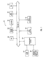
- FIG. 1 shows a block diagram illustrating a navigation system for processing two-dimensional sensor images in accordance with an embodiment of the present invention.
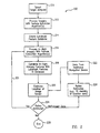
- FIG. 2 shows a flowchart illustrating a method of navigation by processing two-dimensional sensor images in accordance with another embodiment of the present invention.
- Embodiments of the present invention and their advantages are best understood by referring to the detailed description that follows. It should be appreciated that like reference numerals are used to identify like elements illustrated in one or more of the figures. It is also noted that the figures are not necessarily drawn to scale.
- FIG. 1 shows a block diagram illustrating a
navigation system 100 that processes two-dimensional sensor images in accordance with an embodiment of the present invention.System 100 includes a central processing unit (CPU) 102, astorage medium 104 including adatabase 106, read-only memory (ROM) 108, and random access memory (RAM) 110, each element operably coupled to a data bus 112. Animage sensor 114 is also operably coupled to data bus 112 via acommunication interface 118.System 100 may further include auser interface 120 and anoutput communicator 122 operably coupled to data bus 112. -
Image sensor 114 provides data, including but not limited to two-dimensional sensor images for navigation of a missile system, to other elements ofsystem 100 throughcommunication interface 118.Image sensor 114 may include a digital camera, a visible (optical) imager, and/or an infrared imager.Image sensor 114 may also include other means for providing digital images and/or means for converting images to digital images. - Optionally, an additional navigation
system data receiver 116 may also provide data from other navigation devices tosystem 100 throughcommunication interface 118. Additional navigationsystem data receiver 116 may receive data from navigation devices such as a global positioning system (GPS) using a satellite-based navigation system, a direction sensor, and/or other sensors for providing navigational data. In one embodiment,communication interface 118 is also a communication link betweensystem 100 and a remote base station (not shown). - Data through
communication interface 118 is transmitted toCPU 102, which may perform multiple functions, including but not limited to calibration, signal processing, image processing, correlation, and/or guidance functions. - Landmark
feature database 106 stored instorage medium 104 includes extracted objects and features from pre-existing imagery, taken from a previous survey in one example.Database 106 comprises positional data, such as latitude and longitude coordinates, to describe landmark feature positions.Database 106 may further comprise other data representing identification and characteristics of the landmark features, including but not limited to range-dependent data such as size, length, width, and volume, and range-independent data such as color, perimeter squared over area, length over width, and shape. In a further example,database 106 may further include modeling information, map information, and image sensor information.Storage medium 104 may comprise non-volatile memory, a hard disk drive, CD-ROM, or an integrated circuit in which digitized landmark feature information has been stored. Other types of storage media are within the scope of the present invention. - Software for directing the operation of
system 100 may be stored inmain memory 108 for execution byCPU 102.Memory 108 may comprise any of a wide variety of non-volatile memory such as, for example, read-only memory (ROM), reprogrammable non-volatile memory such as flash memory or SRAM, CD ROM, optical disk, or PCMCIA cards. System random access memory (RAM) 110 permits reading and writing of the information necessary to execute such software programs. - Input and output means of
system 100 include auser interface 120 and anoutput communicator 122, respectively. The user may input data, such as a target aimpoint, throughuser interface 120.User interface 120 may be in a remote location from the vehicle or missile in one embodiment.Output communicator 122 receives data processed byCPU 102 and may transmit vehicle location data to vehicle navigation means and/or to the remote base station (not shown). - A method of navigation in accordance with an embodiment of the present invention will now be discussed in greater detail with reference to both FIGS. 1 and 2. FIG. 2 shows a flowchart illustrating a method of
navigation 200 by processing two-dimensional sensor images. - A target aimpoint is selected in
step 210, and in one embodiment may be entered viauser interface 120. - Imagery, from various sources, of an intended area of operation (AOO) is then processed by a feature extraction algorithm or algorithms, as shown in
step 212. Various techniques, such as contrast enhancement or cellular automata for linear or circular features, can be used to identify and extract features, including but not limited to roads, rivers, coastlines, and buildings. - Landmark features may be extracted from imagery through the use of various known techniques, alone or in combination, such as "cellular automata", "contrast enhancement", and/or the Modified Iterated Hough Transform (MIHT) useful in finding "linear" (one-dimensional) features, such as coastlines, rivers, roadways, canyon, or crater rims. "Areal" (two-dimensional) features such as buildings, lakes and reservoirs, and forests, are usually found by examining various thresholds on intensity or color (when color imagery is available) or by looking at linear features that form closed boundaries. Different extraction techniques may also be available for different landmarks.
- To be useful, each extracted feature must have a "point" associated with it. For linear features, points can be extracted from intersections of various linear features (e.g., a river and a road) or from bends, loops, or bifurcations (e.g., a river with an island shows a bifurcation - the stream divides to go around the island) in the linear feature. For areal features the point assigned is usually the centroid of the area. Each point is then identified by its location, for example, its latitude, longitude, and altitude.
- Identified landmark features extracted from existing imagery are then used to create a database, as shown in
step 214. The identified features populate a database, such asdatabase 106, which is stored in a memory, such asstorage medium 104. Such a landmark feature database is then used for subsequent comparison with in-flight sensor data obtained during vehicle/missile flight (step 218). - The landmark database, hereinafter also referred to as the landmark "correspondence point" data set, includes information to identify correspondences between existing imagery and imagery obtained from the vehicle's imaging sensor. In one example, the database can include but is not limited to a cataloging number or name, the correspondence point location (e.g., latitude, longitude, and altitude), and the feature type (feature "primitive" - an image element from which more complicated images can be constructed) or technique used to extract the feature. A set of vectors pointing to the nearest neighboring features may also be included in one embodiment.
- The two-dimensional (2-D) sensor images during vehicle flight are processed by the same or substantially similar algorithm(s) used to extract features used to populate the landmark feature database, as shown in
step 216. In operation, in-flight imagery from the vehicle's sensor is subjected to the same or substantially similar type of feature extraction as was performed to identify features in the imagery used for the correspondence point data set. However, the location of each correspondence point from the in-flight imagery is not known. - The features extracted from the sensor images in
step 216 are then compared with and correlated to the stored landmark feature database to determine the position of the vehicle and/or the vehicle's position relative to the intended target aimpoint, as shown instep 218. - By examining, correlating, and associating the correspondence points from the in-flight imagery with the correspondence points in the database, a registration of the two images may be made based on similarity measures, which include but are not limited to a maximum likelihood estimate considering identification items such as the feature primitives and vectors to the nearest neighbors, and/or a correlation function, which correlates pieces of the vehicle imagery with pieces of the original imagery near each correspondence point. Registration by correlation function requires that the imagery be transformed to a common viewpoint, scale, and orientation, or the correlation may be quite complex requiring either large processing power or processing time. However, the MIHT method reduces the need for image transformation to a common view. Once the registration is made, the location information (e.g., latitude, longitude, and altitude) from the correspondence point data set may be identified with the feature points extracted from the vehicle's in-flight imagery.
- Then, as shown in
step 220, the viewpoint from which the image was taken can be estimated using the ordinary trigonometric calculations of projective geometry (e.g., utilizing scale and orientation of the landmark features) knowing the locations of the various features extracted from the in-flight imagery. This viewpoint estimate may include the location (e.g., latitude, longitude, and altitude) and view angles (azimuth or compass angle and elevation or depression angle) of the image sensor. Accordingly, a 3-D projection based on 2-D images is provided by perspective transformation in accordance with an embodiment of the present invention. - Next, a decision may be made to either refine the viewpoint estimate or not, as shown by
decision block 224. If no, the process ends atstep 228. If yes, an estimate of position, orientation, and velocity may be refined by taking a series of images as illustrated byloop 221, and by fitting the data from the series of images to an assumed curve of location, as shown bystep 226. Normally this curve will be limited to a simple 3rd or 4th order polynomial with terms for initial position, velocity, acceleration, and perhaps jerk, so that a plurality of images (e.g., any set of more than four images) can be used to refine the estimates of the location curve terms (e.g., position, velocity, acceleration) through a least squares fit or other estimating procedure. - Optionally, as shown by
block 222, data from an additional navigation device, such as a GPS, a direction sensor, an inertial sensor, and/or other sensor, may be included withsteps - Embodiments described above illustrate but do not limit the invention. It should also be understood that numerous modifications and variations are possible in accordance with the principles of the present invention. Accordingly, the scope of the invention is defined only by the following claims.
Claims (32)
- A method of navigation, comprising:processing (212) imagery to extract a first set of landmark features with a first extraction algorithm;processing (216) imagery from an image sensor (114) with a second extraction algorithm to extract a second set of landmark features; andcorrelating (218) the second set of landmark features to the first set of landmark features to estimate a location of the image sensor (114).
- The method of claim 1, wherein the first set of landmark features includes a correspondence point location for each extracted landmark feature.
- The method of claim 2, wherein the correspondence point location includes latitude, longitude, and altitude.
- The method of one of claims 1 to 3, wherein the first set of landmark features is extracted with a plurality of extraction algorithms.
- The method of one of claims 1 to 4, wherein the first set of landmark features includes a cataloging number, a name, a feature type, a technique used to extract the feature, and a set of vectors pointing to the nearest neighboring features.
- The method of one of claims 1 to 5, wherein the first and the second set of landmark features includes a cataloging number, a name, a feature type, a technique used to extract the feature, and a set of vectors pointing to the nearest neighboring features.
- The method of one of claims 1 to 6, wherein the second extraction algorithm is substantially similar to the first extraction algorithm.
- The method of one of claims 1 to 7, wherein the second set of landmark features is extracted with a plurality of extraction algorithms.
- The method of one of claims 1 to 8, wherein estimating a location of image sensor (114) includes estimating the latitude, longitude, and altitude of the image sensor (114).
- The method of one of claims 1 to 9, further comprising estimating (220) a velocity and acceleration of the image sensor (114).
- The method of one of claims 1 to 10, further comprising estimating a view angle of the image sensor (114).
- The method of one of claims 1 to 11, further comprising providing (222) data from a navigation device to refine (226) the estimate of the image sensor (114) location.
- The method of one of claims 1 to 12, further comprising repeatedly processing (221) imagery from the image sensor (114) to refine (226) the estimate of the image sensor (114) location.
- The method of claim 13, further comprising fitting estimated location data from repeatedly processing imagery to an estimated location curve.
- The method of one of claims 1 to 14, further comprising selecting (210) a target aimpoint.
- The method of one of claims 1 to 15, further comprising providing a landmark feature database including the first set of landmark features.
- The method of claim 16, whereinpre-existing imagery is processed to extract the first set of landmark features with the first extraction algorithm;two-dimensional imagery is processed from an in-flight image sensor with the second extraction algorithm to extract the second set of landmark features; andthe second set of landmark features is correlated to the landmark feature database to estimate a latitude, longitude, and altitude of the image sensor.
- A method of navigation, comprising:providing a database;processing two-dimensional image data from an airborne sensor (114);comparing the two-dimensional image data to the database; anddetermining a three-dimensional location corresponding to the two-dimensional image data.
- The method of claim 18, wherein the database includes a set of landmark features.
- The method of claim 18 or 19, wherein the two-dimensional image is processed to identify landmark features.
- The method of one of claims 18 to 20, wherein the three-dimensional location includes latitude, longitude, and altitude.
- A navigation system (100), comprising:a database (106) including a first set of landmark features extracted from pre-existing imagery;an airborne image sensor (114) to provide in-flight imagery; anda processor (102) operably coupled to the database (106) and the image sensor (114), wherein the processor (102) is operable to:process imagery from the image sensor (114) to extract a second set of landmark features; andcorrelate the second set of landmark features to the first set of landmark features to estimate a location of the image sensor (114).
- The system of claim 22, wherein the database (106) includes a correspondence point location for each extracted landmark feature.
- The system of claim 23, wherein the correspondence point location includes latitude, longitude, and altitude.
- The system of one of claims 22 to 24, wherein the database (106) includes a cataloging number, a name, a feature type, a technique used to extract the feature, and a set of vectors pointing to the nearest neighboring features.
- The system of one of claims 22 to 25, wherein the first and the second set of landmark features includes a cataloging number, a name, a feature type, a technique used to extract the feature, and a set of vectors pointing to the nearest neighboring features.
- The system of one of claims 22 to 26, wherein the first and the second set of landmark features are extracted with substantially similar extraction algorithms.
- The system of one of claims 22 to 27, wherein the first and the second set of landmark features are extracted with a plurality of extraction algorithms.
- The system of one of claims 22 to 28, wherein the image sensor (114) is selected from the group consisting of a camera, an optical imager, and an infrared imager.
- The system of one of claims 22 to 29, wherein the processor (102) estimates a view angle of the image sensor (114).
- The system of one of claims 22 to 30, wherein the processor (102) repeatedly processes imagery from the image sensor (114) to refine (226) the estimate of the image sensor location.
- The system of one of claims 22 to 31, further comprising a navigation device for providing additional data to refine the estimate of the image sensor location.
Applications Claiming Priority (1)
| Application Number | Priority Date | Filing Date | Title |
|---|---|---|---|
| US11/028,932 US7191056B2 (en) | 2005-01-04 | 2005-01-04 | Precision landmark-aided navigation |
Publications (3)
| Publication Number | Publication Date |
|---|---|
| EP1677076A2 true EP1677076A2 (en) | 2006-07-05 |
| EP1677076A3 EP1677076A3 (en) | 2008-11-19 |
| EP1677076B1 EP1677076B1 (en) | 2017-02-15 |
Family
ID=36123184
Family Applications (1)
| Application Number | Title | Priority Date | Filing Date |
|---|---|---|---|
| EP05028601.2A Active EP1677076B1 (en) | 2005-01-04 | 2005-12-28 | Precision landmark-aided navigation |
Country Status (3)
| Country | Link |
|---|---|
| US (1) | US7191056B2 (en) |
| EP (1) | EP1677076B1 (en) |
| ES (1) | ES2625107T3 (en) |
Cited By (15)
| Publication number | Priority date | Publication date | Assignee | Title |
|---|---|---|---|---|
| EP1926007A2 (en) * | 2006-09-05 | 2008-05-28 | Honeywell International, Inc. | Method and system for navigation of an unmanned aerial vehicle in an urban environment |
| WO2008080606A1 (en) * | 2006-12-29 | 2008-07-10 | Fraunhofer-Gesellschaft zur Förderung der angewandten Forschung e.V. | Device, method, and computer program for determining a position on the basis of a camera image |
| EP1972893A1 (en) * | 2007-03-21 | 2008-09-24 | Universiteit Gent | System and method for position determination |
| EP2107504A1 (en) * | 2008-03-31 | 2009-10-07 | Harman Becker Automotive Systems GmbH | Method and device for generating a real time environment model for vehicles |
| WO2010141209A1 (en) | 2009-06-01 | 2010-12-09 | Robert Bosch Gmbh | Method and apparatus for combining three-dimensional position and two-dimensional intensity mapping for localization |
| WO2011073034A1 (en) | 2009-12-18 | 2011-06-23 | Thales | Method for designating a target for a weapon having terminal guidance via imaging |
| US8315794B1 (en) | 2006-09-05 | 2012-11-20 | Honeywell International Inc. | Method and system for GPS-denied navigation of unmanned aerial vehicles |
| WO2013117940A3 (en) * | 2012-02-10 | 2013-12-05 | Isis Innovation Limited | Method of locating a sensor and related apparatus |
| WO2016148619A1 (en) * | 2015-03-19 | 2016-09-22 | Vricon Systems Aktiebolag | Position determining unit and a method for determining a position of a land or sea based object |
| US9478141B2 (en) | 2011-10-28 | 2016-10-25 | Bae Systems Plc | Identification and analysis of aircraft landing sites |
| US9945950B2 (en) | 2012-04-02 | 2018-04-17 | Oxford University Innovation Limited | Method for localizing a vehicle equipped with two lidar systems |
| EP3340175A1 (en) * | 2016-12-21 | 2018-06-27 | The Boeing Company | Method and apparatus for raw sensor image enhancement through georegistration |
| GB2562571A (en) * | 2017-03-14 | 2018-11-21 | Ford Global Tech Llc | Vehicle localization using cameras |
| GB2568286A (en) * | 2017-11-10 | 2019-05-15 | Horiba Mira Ltd | Method of computer vision based localisation and navigation and system for performing the same |
| US10744322B2 (en) | 2005-09-19 | 2020-08-18 | Fraunhofer-Gesellschaft Zur Foerderung Der Angewandten Forschung E.V. | Cochlear implant, device for generating a control signal for a cochlear implant, device for generating a combination signal and combination signal and corresponding methods |
Families Citing this family (60)
| Publication number | Priority date | Publication date | Assignee | Title |
|---|---|---|---|---|
| US8942483B2 (en) | 2009-09-14 | 2015-01-27 | Trimble Navigation Limited | Image-based georeferencing |
| JP4753103B2 (en) * | 2006-03-31 | 2011-08-24 | 村田機械株式会社 | MOBILE POSITION ESTIMATION DEVICE, ESTIMATION METHOD, AND ESTIMATION PROGRAM |
| US7840352B2 (en) * | 2006-09-05 | 2010-11-23 | Honeywell International Inc. | Method and system for autonomous vehicle navigation |
| US20080153516A1 (en) * | 2006-12-20 | 2008-06-26 | Via Technologies, Inc. | Visual Positioning System and Method for Mobile User Equipment |
| US8532328B2 (en) * | 2007-08-16 | 2013-09-10 | The Boeing Company | Methods and apparatus for planetary navigation |
| US7917289B2 (en) * | 2007-10-30 | 2011-03-29 | Honeywell International Inc. | Perspective view primary flight display system and method with range lines |
| US7970178B2 (en) * | 2007-12-21 | 2011-06-28 | Caterpillar Inc. | Visibility range estimation method and system |
| WO2010088290A1 (en) * | 2009-01-27 | 2010-08-05 | Arthur Thomas D | Tight optical intergation (toi) of images with gps range measurements |
| US9208690B2 (en) * | 2009-03-18 | 2015-12-08 | Saab Ab | Calculating time to go and size of an object based on scale correlation between images from an electro optical sensor |
| US9324003B2 (en) | 2009-09-14 | 2016-04-26 | Trimble Navigation Limited | Location of image capture device and object features in a captured image |
| US8897541B2 (en) * | 2009-09-14 | 2014-11-25 | Trimble Navigation Limited | Accurate digitization of a georeferenced image |
| US8788496B2 (en) * | 2009-09-30 | 2014-07-22 | Trimble Navigation Limited | Visual organization of information via associated geospatial data |
| US9497581B2 (en) * | 2009-12-16 | 2016-11-15 | Trimble Navigation Limited | Incident reporting |
| US9058633B2 (en) | 2010-10-25 | 2015-06-16 | Trimble Navigation Limited | Wide-area agricultural monitoring and prediction |
| US20120101784A1 (en) | 2010-10-25 | 2012-04-26 | Trimble Navigation Limited | Wide-area agricultural monitoring and prediction |
| US9846848B2 (en) | 2010-10-25 | 2017-12-19 | Trimble Inc. | Exchanging water allocation credits |
| US9213905B2 (en) | 2010-10-25 | 2015-12-15 | Trimble Navigation Limited | Automatic obstacle location mapping |
| US8855937B2 (en) | 2010-10-25 | 2014-10-07 | Trimble Navigation Limited | Crop characteristic estimation |
| US10115158B2 (en) | 2010-10-25 | 2018-10-30 | Trimble Inc. | Generating a crop recommendation |
| US8768667B2 (en) | 2010-10-25 | 2014-07-01 | Trimble Navigation Limited | Water erosion management incorporating topography, soil type, and weather statistics |
| US8671741B2 (en) | 2011-06-29 | 2014-03-18 | Trimble Navigation Limited | Extendable moisture content sensing system |
| KR101366860B1 (en) * | 2011-09-20 | 2014-02-21 | 엘지전자 주식회사 | Mobile robot and controlling method of the same |
| EP2579016A1 (en) * | 2011-10-05 | 2013-04-10 | Siemens Aktiengesellschaft | Method and system for monitoring a parameter of a parabolic reflector |
| US8525088B1 (en) | 2012-03-21 | 2013-09-03 | Rosemont Aerospace, Inc. | View-point guided weapon system and target designation method |
| US10068157B2 (en) | 2012-05-10 | 2018-09-04 | Apple Inc. | Automatic detection of noteworthy locations |
| US8949024B2 (en) * | 2012-10-25 | 2015-02-03 | Massachusetts Institute Of Technology | Vehicle localization using surface penetrating radar |
| IL226752A (en) * | 2013-06-04 | 2017-02-28 | Padowicz Ronen | Self-contained navigation system and method |
| US20150130936A1 (en) * | 2013-11-08 | 2015-05-14 | Dow Agrosciences Llc | Crop monitoring system |
| US9541387B2 (en) | 2014-02-07 | 2017-01-10 | Goodrich Corporation | Passive altimeter |
| KR101574876B1 (en) * | 2014-02-13 | 2015-12-04 | 영남대학교 산학협력단 | Distance measuring method using vision sensor database |
| US9360321B2 (en) * | 2014-04-14 | 2016-06-07 | Vricon Systems Aktiebolag | Navigation based on at least one sensor and a three dimensional map |
| US9483842B2 (en) * | 2014-04-14 | 2016-11-01 | Vricon Systems Aktiebolag | Navigation based on at least one sensor and a three dimensional map |
| EP3213251A1 (en) * | 2014-10-27 | 2017-09-06 | FTS Computertechnik GmbH | Computer vision monitoring for a computer vision system |
| IL241200A0 (en) * | 2015-09-06 | 2015-11-30 | Unision Air Ltd | System and method for self-geoposition an unmanned aerial vehicle |
| DE102016205870A1 (en) * | 2016-04-08 | 2017-10-12 | Robert Bosch Gmbh | Method for determining a pose of an at least partially automated vehicle in an environment using landmarks |
| US10048084B2 (en) | 2016-09-16 | 2018-08-14 | The Charles Stark Draper Laboratory, Inc. | Star tracker-aided airborne or spacecraft terrestrial landmark navigation system |
| US10935381B2 (en) | 2016-09-16 | 2021-03-02 | The Charles Stark Draper Laboratory, Inc. | Star tracker-aided airborne or spacecraft terrestrial landmark navigation system |
| KR102595391B1 (en) | 2016-12-07 | 2023-10-31 | 매직 아이 인코포레이티드 | Distance sensor with adjustable focus imaging sensor |
| JP6837690B2 (en) | 2017-01-27 | 2021-03-03 | マサチューセッツ インスティテュート オブ テクノロジー | Vehicle locating method and system using surface penetration radar |
| US10977953B2 (en) * | 2017-02-17 | 2021-04-13 | The Charles Stark Draper Laboratory, Inc. | Probabilistic landmark navigation (PLN) system |
| EP3454079B1 (en) * | 2017-09-12 | 2023-11-01 | Aptiv Technologies Limited | Method to determine the suitablility of a radar target as a positional landmark |
| US10677879B2 (en) | 2017-09-15 | 2020-06-09 | The Boeing Company | Depression angle reference tracking system |
| EP3692396A4 (en) | 2017-10-08 | 2021-07-21 | Magik Eye Inc. | Distance measurement using a longitudinal grid pattern |
| JP2020537242A (en) * | 2017-10-08 | 2020-12-17 | マジック アイ インコーポレイテッド | Calibration of sensor systems including multiple movable sensors |
| US10685229B2 (en) | 2017-12-21 | 2020-06-16 | Wing Aviation Llc | Image based localization for unmanned aerial vehicles, and associated systems and methods |
| KR20200123849A (en) | 2018-03-20 | 2020-10-30 | 매직 아이 인코포레이티드 | Distance measurement using a projection pattern of variable densities |
| CN114827573A (en) | 2018-03-20 | 2022-07-29 | 魔眼公司 | Adjusting camera exposure for three-dimensional depth sensing and two-dimensional imaging |
| EP3803266A4 (en) | 2018-06-06 | 2022-03-09 | Magik Eye Inc. | Distance measurement using high density projection patterns |
| US11475584B2 (en) | 2018-08-07 | 2022-10-18 | Magik Eye Inc. | Baffles for three-dimensional sensors having spherical fields of view |
| CN109491402B (en) * | 2018-11-01 | 2020-10-16 | 中国科学技术大学 | Multi-unmanned aerial vehicle cooperative target monitoring control method based on cluster control |
| WO2020150131A1 (en) | 2019-01-20 | 2020-07-23 | Magik Eye Inc. | Three-dimensional sensor including bandpass filter having multiple passbands |
| US11474209B2 (en) | 2019-03-25 | 2022-10-18 | Magik Eye Inc. | Distance measurement using high density projection patterns |
| US11019249B2 (en) | 2019-05-12 | 2021-05-25 | Magik Eye Inc. | Mapping three-dimensional depth map data onto two-dimensional images |
| CN114641701A (en) * | 2019-09-13 | 2022-06-17 | 波感股份有限公司 | Improved navigation and localization using surface penetrating radar and deep learning |
| CN114730010A (en) | 2019-12-01 | 2022-07-08 | 魔眼公司 | Enhancing triangulation-based three-dimensional distance measurements using time-of-flight information |
| EP4094181A4 (en) | 2019-12-29 | 2024-04-03 | Magik Eye Inc | Associating three-dimensional coordinates with two-dimensional feature points |
| JP2023510738A (en) | 2020-01-05 | 2023-03-15 | マジック アイ インコーポレイテッド | Method of moving the coordinate system of the 3D camera to the incident position of the 2D camera |
| IL274997B2 (en) | 2020-05-27 | 2023-06-01 | Israel Aerospace Ind Ltd | Positioning using satcom |
| US11808578B2 (en) * | 2020-05-29 | 2023-11-07 | Aurora Flight Sciences Corporation | Global positioning denied navigation |
| TWI813118B (en) * | 2021-12-29 | 2023-08-21 | 薩摩亞商動見科技股份有限公司 | System and method for automatically updating visual landmark image database |
Citations (2)
| Publication number | Priority date | Publication date | Assignee | Title |
|---|---|---|---|---|
| US4179693A (en) | 1977-05-23 | 1979-12-18 | Rockwell Internation Corporation | Autonomous, check-pointing, navigational system for an airborne vehicle |
| EP0427431A2 (en) | 1989-11-08 | 1991-05-15 | Smiths Industries Public Limited Company | Navigation systems |
Family Cites Families (8)
| Publication number | Priority date | Publication date | Assignee | Title |
|---|---|---|---|---|
| US4602336A (en) * | 1983-05-16 | 1986-07-22 | Gec Avionics Limited | Guidance systems |
| FR2657160B1 (en) * | 1990-01-12 | 1992-05-07 | Aerospatiale | ON-BOARD SYSTEM FOR DETERMINING THE POSITION OF AN AIR VEHICLE AND ITS APPLICATIONS. |
| US5576964A (en) * | 1992-11-30 | 1996-11-19 | Texas Instruments Incorporated | System and method for relating a passive sensor to a geographic environment |
| US5525883A (en) * | 1994-07-08 | 1996-06-11 | Sara Avitzour | Mobile robot location determination employing error-correcting distributed landmarks |
| US5699444A (en) * | 1995-03-31 | 1997-12-16 | Synthonics Incorporated | Methods and apparatus for using image data to determine camera location and orientation |
| US5999866A (en) * | 1996-11-05 | 1999-12-07 | Carnegie Mellon University | Infrastructure independent position determining system |
| AUPP299498A0 (en) * | 1998-04-15 | 1998-05-07 | Commonwealth Scientific And Industrial Research Organisation | Method of tracking and sensing position of objects |
| US6744397B1 (en) * | 2003-06-11 | 2004-06-01 | Honeywell International, Inc. | Systems and methods for target location |
-
2005
- 2005-01-04 US US11/028,932 patent/US7191056B2/en active Active
- 2005-12-28 ES ES05028601.2T patent/ES2625107T3/en active Active
- 2005-12-28 EP EP05028601.2A patent/EP1677076B1/en active Active
Patent Citations (2)
| Publication number | Priority date | Publication date | Assignee | Title |
|---|---|---|---|---|
| US4179693A (en) | 1977-05-23 | 1979-12-18 | Rockwell Internation Corporation | Autonomous, check-pointing, navigational system for an airborne vehicle |
| EP0427431A2 (en) | 1989-11-08 | 1991-05-15 | Smiths Industries Public Limited Company | Navigation systems |
Cited By (35)
| Publication number | Priority date | Publication date | Assignee | Title |
|---|---|---|---|---|
| US10744322B2 (en) | 2005-09-19 | 2020-08-18 | Fraunhofer-Gesellschaft Zur Foerderung Der Angewandten Forschung E.V. | Cochlear implant, device for generating a control signal for a cochlear implant, device for generating a combination signal and combination signal and corresponding methods |
| US8315794B1 (en) | 2006-09-05 | 2012-11-20 | Honeywell International Inc. | Method and system for GPS-denied navigation of unmanned aerial vehicles |
| EP1926007A3 (en) * | 2006-09-05 | 2012-06-06 | Honeywell International Inc. | Method and system for navigation of an unmanned aerial vehicle in an urban environment |
| EP2735932A1 (en) * | 2006-09-05 | 2014-05-28 | Honeywell International Inc. | Method and system for navigation of an unmanned aerial vehicle in an urban environment |
| EP1926007A2 (en) * | 2006-09-05 | 2008-05-28 | Honeywell International, Inc. | Method and system for navigation of an unmanned aerial vehicle in an urban environment |
| WO2008080606A1 (en) * | 2006-12-29 | 2008-07-10 | Fraunhofer-Gesellschaft zur Förderung der angewandten Forschung e.V. | Device, method, and computer program for determining a position on the basis of a camera image |
| US8121350B2 (en) | 2006-12-29 | 2012-02-21 | Fraunhofer-Gesellschaft Zur Foerderung Der Angewandten Forschung E.V. | Apparatus, method and computer program for determining a position on the basis of a camera image from a camera |
| WO2008113861A3 (en) * | 2007-03-21 | 2008-11-06 | Univ Gent | System and method for position determination |
| WO2008113861A2 (en) * | 2007-03-21 | 2008-09-25 | Universiteit Gent | System and method for position determination |
| EP1972893A1 (en) * | 2007-03-21 | 2008-09-24 | Universiteit Gent | System and method for position determination |
| EP2107504A1 (en) * | 2008-03-31 | 2009-10-07 | Harman Becker Automotive Systems GmbH | Method and device for generating a real time environment model for vehicles |
| WO2010141209A1 (en) | 2009-06-01 | 2010-12-09 | Robert Bosch Gmbh | Method and apparatus for combining three-dimensional position and two-dimensional intensity mapping for localization |
| CN102460074A (en) * | 2009-06-01 | 2012-05-16 | 罗伯特·博世有限公司 | Method and apparatus for combining three-dimensional position and two-dimensional intensity mapping for localization |
| JP2012529012A (en) * | 2009-06-01 | 2012-11-15 | ロベルト ボッシュ ゲーエムベーハー | Method and apparatus for combining 3D position and 2D intensity mapping for localization |
| US8473187B2 (en) | 2009-06-01 | 2013-06-25 | Robert Bosch Gmbh | Method and apparatus for combining three-dimensional position and two-dimensional intensity mapping for localization |
| CN102460074B (en) * | 2009-06-01 | 2015-04-29 | 罗伯特·博世有限公司 | Method and apparatus for combining three-dimensional position and two-dimensional intensity mapping for localization |
| FR2954520A1 (en) * | 2009-12-18 | 2011-06-24 | Thales Sa | METHOD FOR THE DESIGNATION OF A TARGET FOR A TERMINAL IMAGING GUIDED ARMING |
| WO2011073034A1 (en) | 2009-12-18 | 2011-06-23 | Thales | Method for designating a target for a weapon having terminal guidance via imaging |
| US9478141B2 (en) | 2011-10-28 | 2016-10-25 | Bae Systems Plc | Identification and analysis of aircraft landing sites |
| WO2013117940A3 (en) * | 2012-02-10 | 2013-12-05 | Isis Innovation Limited | Method of locating a sensor and related apparatus |
| US9576206B2 (en) | 2012-02-10 | 2017-02-21 | Oxford University Innovation Limited | Method of locating a sensor and related apparatus |
| JP2018009999A (en) * | 2012-02-10 | 2018-01-18 | オックスフォード ユニヴァーシティ イノヴェーション リミテッド | Method for estimating position of sensor and related devices |
| CN104520732A (en) * | 2012-02-10 | 2015-04-15 | Isis创新有限公司 | Method of locating sensor and related apparatus |
| US9945950B2 (en) | 2012-04-02 | 2018-04-17 | Oxford University Innovation Limited | Method for localizing a vehicle equipped with two lidar systems |
| US10036636B2 (en) | 2015-03-19 | 2018-07-31 | Vricon Systems Aktiebolag | Position determining unit and a method for determining a position of a land or sea based object |
| WO2016148619A1 (en) * | 2015-03-19 | 2016-09-22 | Vricon Systems Aktiebolag | Position determining unit and a method for determining a position of a land or sea based object |
| JP2018112543A (en) * | 2016-12-21 | 2018-07-19 | ザ・ボーイング・カンパニーThe Boeing Company | Method and apparatus for raw sensor image enhancement through georegistration |
| EP3340175A1 (en) * | 2016-12-21 | 2018-06-27 | The Boeing Company | Method and apparatus for raw sensor image enhancement through georegistration |
| US10802135B2 (en) | 2016-12-21 | 2020-10-13 | The Boeing Company | Method and apparatus for raw sensor image enhancement through georegistration |
| JP7138428B2 (en) | 2016-12-21 | 2022-09-16 | ザ・ボーイング・カンパニー | Method and apparatus for raw sensor image enhancement through geo-registration |
| GB2562571A (en) * | 2017-03-14 | 2018-11-21 | Ford Global Tech Llc | Vehicle localization using cameras |
| GB2568286A (en) * | 2017-11-10 | 2019-05-15 | Horiba Mira Ltd | Method of computer vision based localisation and navigation and system for performing the same |
| WO2019092418A1 (en) * | 2017-11-10 | 2019-05-16 | Horiba Mira Limited | Method of computer vision based localisation and navigation and system for performing the same |
| GB2568286B (en) * | 2017-11-10 | 2020-06-10 | Horiba Mira Ltd | Method of computer vision based localisation and navigation and system for performing the same |
| US11393216B2 (en) | 2017-11-10 | 2022-07-19 | Horiba Mira Limited | Method of computer vision based localisation and navigation and system for performing the same |
Also Published As
| Publication number | Publication date |
|---|---|
| ES2625107T3 (en) | 2017-07-18 |
| US20060149458A1 (en) | 2006-07-06 |
| EP1677076B1 (en) | 2017-02-15 |
| EP1677076A3 (en) | 2008-11-19 |
| US7191056B2 (en) | 2007-03-13 |
Similar Documents
| Publication | Publication Date | Title |
|---|---|---|
| US7191056B2 (en) | Precision landmark-aided navigation | |
| US10515458B1 (en) | Image-matching navigation method and apparatus for aerial vehicles | |
| Wen et al. | GNSS NLOS exclusion based on dynamic object detection using LiDAR point cloud | |
| EP2749842B1 (en) | System and method for collaborative navigation | |
| CN110945379A (en) | Determining yaw error from map data, laser, and camera | |
| EP3707466A1 (en) | Method of computer vision based localisation and navigation and system for performing the same | |
| US7408629B2 (en) | Passive measurement of terrain parameters | |
| CN110873570B (en) | Method and apparatus for sourcing, generating and updating a map representing a location | |
| Qu et al. | Landmark based localization in urban environment | |
| US20100176987A1 (en) | Method and apparatus to estimate vehicle position and recognized landmark positions using GPS and camera | |
| EP2573584A1 (en) | Generic surface feature extraction from a set of range data | |
| CN108426576B (en) | Aircraft path planning method and system based on identification point visual navigation and SINS | |
| CN112805766B (en) | Apparatus and method for updating detailed map | |
| KR102396929B1 (en) | 2d vehicle localizing using geoarcs | |
| US20120232717A1 (en) | Remote coordinate identifier system and method for aircraft | |
| KR102239562B1 (en) | Fusion system between airborne and terrestrial observation data | |
| Dumble et al. | Airborne vision-aided navigation using road intersection features | |
| KR20200094654A (en) | Method and device for localization of autonomous vehicle for route planning by using attention-driven landmark detection | |
| JP7114165B2 (en) | Position calculation device and position calculation program | |
| Greco et al. | SAR and InSAR georeferencing algorithms for inertial navigation systems | |
| US11866167B2 (en) | Method and algorithm for flight, movement, autonomy, in GPS, communication, degraded, denied, obstructed non optimal environment | |
| JP6989284B2 (en) | Vehicle position estimation device and program | |
| Gustafsson et al. | Navigation and tracking of road-bound vehicles | |
| Chellappa et al. | On the positioning of multisensor imagery for exploitation and target recognition | |
| EP2211144A1 (en) | Systems and methods for determining location of an airborne vehicle using radar images |
Legal Events
| Date | Code | Title | Description |
|---|---|---|---|
| PUAI | Public reference made under article 153(3) epc to a published international application that has entered the european phase |
Free format text: ORIGINAL CODE: 0009012 |
|
| AK | Designated contracting states |
Kind code of ref document: A2 Designated state(s): AT BE BG CH CY CZ DE DK EE ES FI FR GB GR HU IE IS IT LI LT LU LV MC NL PL PT RO SE SI SK TR |
|
| AX | Request for extension of the european patent |
Extension state: AL BA HR MK YU |
|
| PUAL | Search report despatched |
Free format text: ORIGINAL CODE: 0009013 |
|
| AK | Designated contracting states |
Kind code of ref document: A3 Designated state(s): AT BE BG CH CY CZ DE DK EE ES FI FR GB GR HU IE IS IT LI LT LU LV MC NL PL PT RO SE SI SK TR |
|
| AX | Request for extension of the european patent |
Extension state: AL BA HR MK YU |
|
| 17P | Request for examination filed |
Effective date: 20090511 |
|
| AKX | Designation fees paid |
Designated state(s): AT BE BG CH CY CZ DE DK EE ES FI FR GB GR HU IE IS IT LI LT LU LV MC NL PL PT RO SE SI SK TR |
|
| 17Q | First examination report despatched |
Effective date: 20090708 |
|
| GRAP | Despatch of communication of intention to grant a patent |
Free format text: ORIGINAL CODE: EPIDOSNIGR1 |
|
| RIC1 | Information provided on ipc code assigned before grant |
Ipc: G01C 21/00 20060101AFI20160721BHEP Ipc: G06T 7/00 20060101ALN20160721BHEP |
|
| RIC1 | Information provided on ipc code assigned before grant |
Ipc: G01C 21/00 20060101AFI20160727BHEP Ipc: G06T 7/00 20060101ALN20160727BHEP |
|
| INTG | Intention to grant announced |
Effective date: 20160810 |
|
| RIC1 | Information provided on ipc code assigned before grant |
Ipc: G06T 7/00 20060101ALN20160729BHEP Ipc: G01C 21/00 20060101AFI20160729BHEP |
|
| GRAS | Grant fee paid |
Free format text: ORIGINAL CODE: EPIDOSNIGR3 |
|
| GRAA | (expected) grant |
Free format text: ORIGINAL CODE: 0009210 |
|
| AK | Designated contracting states |
Kind code of ref document: B1 Designated state(s): AT BE BG CH CY CZ DE DK EE ES FI FR GB GR HU IE IS IT LI LT LU LV MC NL PL PT RO SE SI SK TR |
|
| REG | Reference to a national code |
Ref country code: CH Ref legal event code: EP Ref country code: GB Ref legal event code: FG4D |
|
| REG | Reference to a national code |
Ref country code: IE Ref legal event code: FG4D |
|
| REG | Reference to a national code |
Ref country code: AT Ref legal event code: REF Ref document number: 868161 Country of ref document: AT Kind code of ref document: T Effective date: 20170315 |
|
| REG | Reference to a national code |
Ref country code: DE Ref legal event code: R096 Ref document number: 602005051311 Country of ref document: DE |
|
| REG | Reference to a national code |
Ref country code: NL Ref legal event code: MP Effective date: 20170215 |
|
| REG | Reference to a national code |
Ref country code: LT Ref legal event code: MG4D |
|
| REG | Reference to a national code |
Ref country code: AT Ref legal event code: MK05 Ref document number: 868161 Country of ref document: AT Kind code of ref document: T Effective date: 20170215 |
|
| REG | Reference to a national code |
Ref country code: ES Ref legal event code: FG2A Ref document number: 2625107 Country of ref document: ES Kind code of ref document: T3 Effective date: 20170718 |
|
| PG25 | Lapsed in a contracting state [announced via postgrant information from national office to epo] |
Ref country code: LT Free format text: LAPSE BECAUSE OF FAILURE TO SUBMIT A TRANSLATION OF THE DESCRIPTION OR TO PAY THE FEE WITHIN THE PRESCRIBED TIME-LIMIT Effective date: 20170215 Ref country code: FI Free format text: LAPSE BECAUSE OF FAILURE TO SUBMIT A TRANSLATION OF THE DESCRIPTION OR TO PAY THE FEE WITHIN THE PRESCRIBED TIME-LIMIT Effective date: 20170215 Ref country code: GR Free format text: LAPSE BECAUSE OF FAILURE TO SUBMIT A TRANSLATION OF THE DESCRIPTION OR TO PAY THE FEE WITHIN THE PRESCRIBED TIME-LIMIT Effective date: 20170516 |
|
| PG25 | Lapsed in a contracting state [announced via postgrant information from national office to epo] |
Ref country code: NL Free format text: LAPSE BECAUSE OF FAILURE TO SUBMIT A TRANSLATION OF THE DESCRIPTION OR TO PAY THE FEE WITHIN THE PRESCRIBED TIME-LIMIT Effective date: 20170215 Ref country code: BG Free format text: LAPSE BECAUSE OF FAILURE TO SUBMIT A TRANSLATION OF THE DESCRIPTION OR TO PAY THE FEE WITHIN THE PRESCRIBED TIME-LIMIT Effective date: 20170515 Ref country code: SE Free format text: LAPSE BECAUSE OF FAILURE TO SUBMIT A TRANSLATION OF THE DESCRIPTION OR TO PAY THE FEE WITHIN THE PRESCRIBED TIME-LIMIT Effective date: 20170215 Ref country code: PT Free format text: LAPSE BECAUSE OF FAILURE TO SUBMIT A TRANSLATION OF THE DESCRIPTION OR TO PAY THE FEE WITHIN THE PRESCRIBED TIME-LIMIT Effective date: 20170615 Ref country code: AT Free format text: LAPSE BECAUSE OF FAILURE TO SUBMIT A TRANSLATION OF THE DESCRIPTION OR TO PAY THE FEE WITHIN THE PRESCRIBED TIME-LIMIT Effective date: 20170215 Ref country code: LV Free format text: LAPSE BECAUSE OF FAILURE TO SUBMIT A TRANSLATION OF THE DESCRIPTION OR TO PAY THE FEE WITHIN THE PRESCRIBED TIME-LIMIT Effective date: 20170215 |
|
| PG25 | Lapsed in a contracting state [announced via postgrant information from national office to epo] |
Ref country code: RO Free format text: LAPSE BECAUSE OF FAILURE TO SUBMIT A TRANSLATION OF THE DESCRIPTION OR TO PAY THE FEE WITHIN THE PRESCRIBED TIME-LIMIT Effective date: 20170215 Ref country code: CZ Free format text: LAPSE BECAUSE OF FAILURE TO SUBMIT A TRANSLATION OF THE DESCRIPTION OR TO PAY THE FEE WITHIN THE PRESCRIBED TIME-LIMIT Effective date: 20170215 Ref country code: SK Free format text: LAPSE BECAUSE OF FAILURE TO SUBMIT A TRANSLATION OF THE DESCRIPTION OR TO PAY THE FEE WITHIN THE PRESCRIBED TIME-LIMIT Effective date: 20170215 Ref country code: EE Free format text: LAPSE BECAUSE OF FAILURE TO SUBMIT A TRANSLATION OF THE DESCRIPTION OR TO PAY THE FEE WITHIN THE PRESCRIBED TIME-LIMIT Effective date: 20170215 |
|
| REG | Reference to a national code |
Ref country code: DE Ref legal event code: R097 Ref document number: 602005051311 Country of ref document: DE |
|
| PG25 | Lapsed in a contracting state [announced via postgrant information from national office to epo] |
Ref country code: PL Free format text: LAPSE BECAUSE OF FAILURE TO SUBMIT A TRANSLATION OF THE DESCRIPTION OR TO PAY THE FEE WITHIN THE PRESCRIBED TIME-LIMIT Effective date: 20170215 Ref country code: DK Free format text: LAPSE BECAUSE OF FAILURE TO SUBMIT A TRANSLATION OF THE DESCRIPTION OR TO PAY THE FEE WITHIN THE PRESCRIBED TIME-LIMIT Effective date: 20170215 |
|
| PLBE | No opposition filed within time limit |
Free format text: ORIGINAL CODE: 0009261 |
|
| STAA | Information on the status of an ep patent application or granted ep patent |
Free format text: STATUS: NO OPPOSITION FILED WITHIN TIME LIMIT |
|
| REG | Reference to a national code |
Ref country code: FR Ref legal event code: PLFP Year of fee payment: 13 |
|
| 26N | No opposition filed |
Effective date: 20171116 |
|
| PG25 | Lapsed in a contracting state [announced via postgrant information from national office to epo] |
Ref country code: SI Free format text: LAPSE BECAUSE OF FAILURE TO SUBMIT A TRANSLATION OF THE DESCRIPTION OR TO PAY THE FEE WITHIN THE PRESCRIBED TIME-LIMIT Effective date: 20170215 |
|
| REG | Reference to a national code |
Ref country code: CH Ref legal event code: PL |
|
| REG | Reference to a national code |
Ref country code: IE Ref legal event code: MM4A |
|
| PG25 | Lapsed in a contracting state [announced via postgrant information from national office to epo] |
Ref country code: LU Free format text: LAPSE BECAUSE OF NON-PAYMENT OF DUE FEES Effective date: 20171228 |
|
| REG | Reference to a national code |
Ref country code: BE Ref legal event code: MM Effective date: 20171231 |
|
| PG25 | Lapsed in a contracting state [announced via postgrant information from national office to epo] |
Ref country code: IE Free format text: LAPSE BECAUSE OF NON-PAYMENT OF DUE FEES Effective date: 20171228 |
|
| PG25 | Lapsed in a contracting state [announced via postgrant information from national office to epo] |
Ref country code: BE Free format text: LAPSE BECAUSE OF NON-PAYMENT OF DUE FEES Effective date: 20171231 Ref country code: CH Free format text: LAPSE BECAUSE OF NON-PAYMENT OF DUE FEES Effective date: 20171231 Ref country code: LI Free format text: LAPSE BECAUSE OF NON-PAYMENT OF DUE FEES Effective date: 20171231 |
|
| PG25 | Lapsed in a contracting state [announced via postgrant information from national office to epo] |
Ref country code: HU Free format text: LAPSE BECAUSE OF FAILURE TO SUBMIT A TRANSLATION OF THE DESCRIPTION OR TO PAY THE FEE WITHIN THE PRESCRIBED TIME-LIMIT; INVALID AB INITIO Effective date: 20051228 Ref country code: MC Free format text: LAPSE BECAUSE OF FAILURE TO SUBMIT A TRANSLATION OF THE DESCRIPTION OR TO PAY THE FEE WITHIN THE PRESCRIBED TIME-LIMIT Effective date: 20170215 |
|
| PG25 | Lapsed in a contracting state [announced via postgrant information from national office to epo] |
Ref country code: CY Free format text: LAPSE BECAUSE OF NON-PAYMENT OF DUE FEES Effective date: 20170215 |
|
| PG25 | Lapsed in a contracting state [announced via postgrant information from national office to epo] |
Ref country code: TR Free format text: LAPSE BECAUSE OF FAILURE TO SUBMIT A TRANSLATION OF THE DESCRIPTION OR TO PAY THE FEE WITHIN THE PRESCRIBED TIME-LIMIT Effective date: 20170215 |
|
| PG25 | Lapsed in a contracting state [announced via postgrant information from national office to epo] |
Ref country code: IS Free format text: LAPSE BECAUSE OF FAILURE TO SUBMIT A TRANSLATION OF THE DESCRIPTION OR TO PAY THE FEE WITHIN THE PRESCRIBED TIME-LIMIT Effective date: 20170615 |
|
| PGFP | Annual fee paid to national office [announced via postgrant information from national office to epo] |
Ref country code: ES Payment date: 20230102 Year of fee payment: 18 |
|
| PGFP | Annual fee paid to national office [announced via postgrant information from national office to epo] |
Ref country code: DE Payment date: 20221228 Year of fee payment: 18 |
|
| P01 | Opt-out of the competence of the unified patent court (upc) registered |
Effective date: 20230503 |
|
| PGFP | Annual fee paid to national office [announced via postgrant information from national office to epo] |
Ref country code: GB Payment date: 20231227 Year of fee payment: 19 |
|
| PGFP | Annual fee paid to national office [announced via postgrant information from national office to epo] |
Ref country code: IT Payment date: 20231220 Year of fee payment: 19 Ref country code: FR Payment date: 20231227 Year of fee payment: 19 |
|
| PGFP | Annual fee paid to national office [announced via postgrant information from national office to epo] |
Ref country code: ES Payment date: 20240102 Year of fee payment: 19 |