EP1677055A1 - Multi-type air conditioner - Google Patents
Multi-type air conditioner Download PDFInfo
- Publication number
- EP1677055A1 EP1677055A1 EP05258097A EP05258097A EP1677055A1 EP 1677055 A1 EP1677055 A1 EP 1677055A1 EP 05258097 A EP05258097 A EP 05258097A EP 05258097 A EP05258097 A EP 05258097A EP 1677055 A1 EP1677055 A1 EP 1677055A1
- Authority
- EP
- European Patent Office
- Prior art keywords
- refrigerant
- outdoor
- units
- air conditioner
- tube
- Prior art date
- Legal status (The legal status is an assumption and is not a legal conclusion. Google has not performed a legal analysis and makes no representation as to the accuracy of the status listed.)
- Withdrawn
Links
Images


Classifications
-
- F—MECHANICAL ENGINEERING; LIGHTING; HEATING; WEAPONS; BLASTING
- F24—HEATING; RANGES; VENTILATING
- F24F—AIR-CONDITIONING; AIR-HUMIDIFICATION; VENTILATION; USE OF AIR CURRENTS FOR SCREENING
- F24F11/00—Control or safety arrangements
- F24F11/30—Control or safety arrangements for purposes related to the operation of the system, e.g. for safety or monitoring
- F24F11/49—Control or safety arrangements for purposes related to the operation of the system, e.g. for safety or monitoring ensuring correct operation, e.g. by trial operation or configuration checks
-
- F—MECHANICAL ENGINEERING; LIGHTING; HEATING; WEAPONS; BLASTING
- F24—HEATING; RANGES; VENTILATING
- F24F—AIR-CONDITIONING; AIR-HUMIDIFICATION; VENTILATION; USE OF AIR CURRENTS FOR SCREENING
- F24F11/00—Control or safety arrangements
- F24F11/62—Control or safety arrangements characterised by the type of control or by internal processing, e.g. using fuzzy logic, adaptive control or estimation of values
-
- F—MECHANICAL ENGINEERING; LIGHTING; HEATING; WEAPONS; BLASTING
- F24—HEATING; RANGES; VENTILATING
- F24F—AIR-CONDITIONING; AIR-HUMIDIFICATION; VENTILATION; USE OF AIR CURRENTS FOR SCREENING
- F24F11/00—Control or safety arrangements
- F24F11/70—Control systems characterised by their outputs; Constructional details thereof
- F24F11/80—Control systems characterised by their outputs; Constructional details thereof for controlling the temperature of the supplied air
- F24F11/83—Control systems characterised by their outputs; Constructional details thereof for controlling the temperature of the supplied air by controlling the supply of heat-exchange fluids to heat-exchangers
- F24F11/84—Control systems characterised by their outputs; Constructional details thereof for controlling the temperature of the supplied air by controlling the supply of heat-exchange fluids to heat-exchangers using valves
-
- F—MECHANICAL ENGINEERING; LIGHTING; HEATING; WEAPONS; BLASTING
- F25—REFRIGERATION OR COOLING; COMBINED HEATING AND REFRIGERATION SYSTEMS; HEAT PUMP SYSTEMS; MANUFACTURE OR STORAGE OF ICE; LIQUEFACTION SOLIDIFICATION OF GASES
- F25B—REFRIGERATION MACHINES, PLANTS OR SYSTEMS; COMBINED HEATING AND REFRIGERATION SYSTEMS; HEAT PUMP SYSTEMS
- F25B13/00—Compression machines, plants or systems, with reversible cycle
-
- F—MECHANICAL ENGINEERING; LIGHTING; HEATING; WEAPONS; BLASTING
- F25—REFRIGERATION OR COOLING; COMBINED HEATING AND REFRIGERATION SYSTEMS; HEAT PUMP SYSTEMS; MANUFACTURE OR STORAGE OF ICE; LIQUEFACTION SOLIDIFICATION OF GASES
- F25B—REFRIGERATION MACHINES, PLANTS OR SYSTEMS; COMBINED HEATING AND REFRIGERATION SYSTEMS; HEAT PUMP SYSTEMS
- F25B41/00—Fluid-circulation arrangements
- F25B41/20—Disposition of valves, e.g. of on-off valves or flow control valves
-
- F—MECHANICAL ENGINEERING; LIGHTING; HEATING; WEAPONS; BLASTING
- F25—REFRIGERATION OR COOLING; COMBINED HEATING AND REFRIGERATION SYSTEMS; HEAT PUMP SYSTEMS; MANUFACTURE OR STORAGE OF ICE; LIQUEFACTION SOLIDIFICATION OF GASES
- F25B—REFRIGERATION MACHINES, PLANTS OR SYSTEMS; COMBINED HEATING AND REFRIGERATION SYSTEMS; HEAT PUMP SYSTEMS
- F25B2313/00—Compression machines, plants or systems with reversible cycle not otherwise provided for
- F25B2313/007—Compression machines, plants or systems with reversible cycle not otherwise provided for three pipes connecting the outdoor side to the indoor side with multiple indoor units
-
- F—MECHANICAL ENGINEERING; LIGHTING; HEATING; WEAPONS; BLASTING
- F25—REFRIGERATION OR COOLING; COMBINED HEATING AND REFRIGERATION SYSTEMS; HEAT PUMP SYSTEMS; MANUFACTURE OR STORAGE OF ICE; LIQUEFACTION SOLIDIFICATION OF GASES
- F25B—REFRIGERATION MACHINES, PLANTS OR SYSTEMS; COMBINED HEATING AND REFRIGERATION SYSTEMS; HEAT PUMP SYSTEMS
- F25B2313/00—Compression machines, plants or systems with reversible cycle not otherwise provided for
- F25B2313/023—Compression machines, plants or systems with reversible cycle not otherwise provided for using multiple indoor units
- F25B2313/0231—Compression machines, plants or systems with reversible cycle not otherwise provided for using multiple indoor units with simultaneous cooling and heating
-
- F—MECHANICAL ENGINEERING; LIGHTING; HEATING; WEAPONS; BLASTING
- F25—REFRIGERATION OR COOLING; COMBINED HEATING AND REFRIGERATION SYSTEMS; HEAT PUMP SYSTEMS; MANUFACTURE OR STORAGE OF ICE; LIQUEFACTION SOLIDIFICATION OF GASES
- F25B—REFRIGERATION MACHINES, PLANTS OR SYSTEMS; COMBINED HEATING AND REFRIGERATION SYSTEMS; HEAT PUMP SYSTEMS
- F25B2313/00—Compression machines, plants or systems with reversible cycle not otherwise provided for
- F25B2313/025—Compression machines, plants or systems with reversible cycle not otherwise provided for using multiple outdoor units
- F25B2313/0252—Compression machines, plants or systems with reversible cycle not otherwise provided for using multiple outdoor units with bypasses
-
- F—MECHANICAL ENGINEERING; LIGHTING; HEATING; WEAPONS; BLASTING
- F25—REFRIGERATION OR COOLING; COMBINED HEATING AND REFRIGERATION SYSTEMS; HEAT PUMP SYSTEMS; MANUFACTURE OR STORAGE OF ICE; LIQUEFACTION SOLIDIFICATION OF GASES
- F25B—REFRIGERATION MACHINES, PLANTS OR SYSTEMS; COMBINED HEATING AND REFRIGERATION SYSTEMS; HEAT PUMP SYSTEMS
- F25B2313/00—Compression machines, plants or systems with reversible cycle not otherwise provided for
- F25B2313/025—Compression machines, plants or systems with reversible cycle not otherwise provided for using multiple outdoor units
- F25B2313/0253—Compression machines, plants or systems with reversible cycle not otherwise provided for using multiple outdoor units in parallel arrangements
-
- F—MECHANICAL ENGINEERING; LIGHTING; HEATING; WEAPONS; BLASTING
- F25—REFRIGERATION OR COOLING; COMBINED HEATING AND REFRIGERATION SYSTEMS; HEAT PUMP SYSTEMS; MANUFACTURE OR STORAGE OF ICE; LIQUEFACTION SOLIDIFICATION OF GASES
- F25B—REFRIGERATION MACHINES, PLANTS OR SYSTEMS; COMBINED HEATING AND REFRIGERATION SYSTEMS; HEAT PUMP SYSTEMS
- F25B2400/00—Component parts or details not otherwise provided for in this subclass
- F25B2400/07—Details of compressors or related parts
- F25B2400/075—Details of compressors or related parts with parallel compressors
-
- F—MECHANICAL ENGINEERING; LIGHTING; HEATING; WEAPONS; BLASTING
- F25—REFRIGERATION OR COOLING; COMBINED HEATING AND REFRIGERATION SYSTEMS; HEAT PUMP SYSTEMS; MANUFACTURE OR STORAGE OF ICE; LIQUEFACTION SOLIDIFICATION OF GASES
- F25B—REFRIGERATION MACHINES, PLANTS OR SYSTEMS; COMBINED HEATING AND REFRIGERATION SYSTEMS; HEAT PUMP SYSTEMS
- F25B2400/00—Component parts or details not otherwise provided for in this subclass
- F25B2400/19—Pumping down refrigerant from one part of the cycle to another part of the cycle, e.g. when the cycle is changed from cooling to heating, or before a defrost cycle is started
-
- F—MECHANICAL ENGINEERING; LIGHTING; HEATING; WEAPONS; BLASTING
- F25—REFRIGERATION OR COOLING; COMBINED HEATING AND REFRIGERATION SYSTEMS; HEAT PUMP SYSTEMS; MANUFACTURE OR STORAGE OF ICE; LIQUEFACTION SOLIDIFICATION OF GASES
- F25B—REFRIGERATION MACHINES, PLANTS OR SYSTEMS; COMBINED HEATING AND REFRIGERATION SYSTEMS; HEAT PUMP SYSTEMS
- F25B2500/00—Problems to be solved
- F25B2500/06—Damage
Definitions
- the present invention relates to an air conditioner.
- an air conditioner is a device for cooling or heating in order to provide a comfortable indoor climate, which draws in indoor air, heats or cools the indoor air, and discharges the heated or cooled air to a confined space.
- multi-type air conditioners which include a plurality of compressors or a plurality of outdoor units connected to each other in parallel, have been developed.
- a conventional multi-type air conditioner includes a plurality of compressors, a plurality of indoor units, and refrigerant tubes for connecting the outdoor units to the indoor units.
- Each of the plural outdoor units includes a compressor for compressing low-temperature/low-pressure gas refrigerant into high-pressure gas refrigerant, an outdoor heat exchanger for performing heat exchange between circulated refrigerant and outdoor air, and a four-way valve for switching the direction of the refrigerant flow according which of the heating mode and the cooling mode is being used.
- Each of the indoor units includes an expansion device and an indoor heat exchanger for performing heat exchange between the circulated refrigerant and indoor air.
- the refrigerant compressed by the compressor is fed to the outdoor units by the four-way valve in the cooling mode.
- the refrigerant passing through the outdoor heat exchangers is condensed due to heat exchange between the refrigerant and ambient air and is fed to the expansion device.
- the refrigerant expanded by the expansion device enters the indoor units and is evaporated by absorbing heat from indoor air, thereby cooling the indoor air.
- the four-way valve switches the refrigerant path configuration so that the refrigerant discharged from the compressor passes through the four-way valve, the indoor units, the expansion device, the outdoor units, and the four-way valve to heat a confined space.
- the conventional multi-type air conditioner when any one of the compressors installed in the plural outdoor units malfunctions, the conventional multi-type air conditioner can only be re-operated after all of the refrigerant circulating through the multi-type air conditioner has been discharged, the malfunctioning compressor replaced, vacuum applied to the multi-type air conditioner, and the multi-type air conditioner refilled with refrigerant. Thus, all heating and cooling operations must be stopped and replacement of the malfunctioning compressor is considerably time consuming and expensive.
- the present invention has been made in view of the above and/or other problems, and it is an object of embodiments of the present invention to provide a multi-type air conditioner for simultaneous heating and cooling use in which a compressor can be replaced without stopping heating and cooling operations when the compressor malfunctions so that it is convenient to use and costs can be reduce.
- a multi-type air conditioner for simultaneous heating and cooling use is disclosed in which refrigerant in a malfunctioning outdoor unit of plural outdoor units is withdrawn to other outdoor units such that the other outdoor units work normally, whereby a compressor can be replaced and/or the malfunctioning outdoor unit can be repaired without stopping heating and cooling operations.
- a multi-type air conditioner for simultaneous heating and cooling use including: a plurality of outdoor units respectively including a compressor unit, a four-way valve, and an outdoor heat exchanger; a plurality of indoor units respectively including an indoor heat exchanger and an electronic expansion valve; a distributor installed between the plural outdoor units and the plural indoor units to selectively guide refrigerant to the plural indoor units according to operation conditions of a cooling mode, a heating mode, and a cooling and heating mode; and a refrigerant withdrawing device installed between the plural outdoor units to withdraw the refrigerant from a malfunctioning outdoor unit to the other outdoor units when a compressor unit in the malfunctioning outdoor unit among the plural outdoor units is replaced.
- the refrigerant withdrawing device includes refrigerant withdrawing tubes for withdrawing the refrigerant discharged from the compressor unit of the malfunctioning outdoor unit among the plural outdoor units to the other outdoor unit, and opening and closing valves for opening and closing the refrigerant withdrawing tubes.
- the compressor unit may include one side to which a compressor suction tube, through which the refrigerant is sucked from the indoor units, is connected, and another side to which a bypass for bypassing the discharged refrigerant such that the refrigerant does not pass through the outdoor heat exchangers is connected.
- the refrigerant withdrawing tubes may connect the bypass of the malfunctioning outdoor unit to the compressor suction tube of the other outdoor units.
- the distributor may include a high-pressure refrigerant tube for guiding high-pressure gas refrigerant discharged from the compressor unit to the indoor unit for performing the heating operation, a low-pressure refrigerant tube for guiding refrigerant passing through the first, second, third, fourth, fifth, and sixth indoor units to a suction port of the compressor, a liquid refrigerant tube for guiding liquid refrigerant discharged from the outdoor heat exchangers to the indoor units for performing cooling operation, and a valve device for selectively opening and closing the high-pressure refrigerant tube and the low-pressure refrigerant tub.
- the outdoor unit may further include an outdoor discharge tube for guiding the liquid refrigerant discharged from the outdoor heat exchangers.
- the compressor suction tubes, the bypasses, and the outdoor heat exchanger discharge tubes may be respectively connected to the low-pressure refrigerant tube, the high-pressure refrigerant tube, and the liquid refrigerant tube by service valves.
- a method for withdrawing refrigerant of a multi-type air conditioner for simultaneous heating and cooling use including: a first step of blocking the refrigerant flow to indoor units by closing a service valve installed in a malfunctioning outdoor unit among a plurality of outdoor units when one of the plural outdoor units malfunctions; a second step of opening an opening and closing valve installed in a refrigerant withdrawing tube of the malfunctioned outdoor unit; a third step of operating compressor units of the other outdoor units to pump down to withdraw the refrigerant in the malfunctioning outdoor unit to the other outdoor units; a fourth step of closing the opening and closing valve once all of the refrigerant in the malfunctioning outdoor unit is withdrawn; and a fifth step of replacing a compressor unit of the malfunctioning outdoor unit and normally operating the other outdoor units.
- the first step further comprises the sub-step of closing a service valve for connecting compressor suction tubes of the other outdoor units to the distributor.
- the fourth step may further include the sub-step of opening a service valve of the other outdoor units.
- the multi-type air conditioner for simultaneous heating and cooling use includes a plurality of outdoor units 10, a plurality of indoor units 20, a distributor 30, disposed between the plural outdoor units 10 and the plural indoor units 20, to selectively guide refrigerant to the plural indoor units 20 according to the operating mode, i.e. a cooling mode, a heating mode, or a cooling and heating mode, and a refrigerant withdrawing device for withdrawing the refrigerant from a malfunctioning outdoor unit among the plural outdoor units 10 to other outdoor units when replacing a part of the malfunctioning outdoor unit.
- the operating mode i.e. a cooling mode, a heating mode, or a cooling and heating mode
- a refrigerant withdrawing device for withdrawing the refrigerant from a malfunctioning outdoor unit among the plural outdoor units 10 to other outdoor units when replacing a part of the malfunctioning outdoor unit.
- the plural outdoor units 10 include three outdoor units, i.e. first, second, and third outdoor units 51, 52, and 53. Only the plural outdoor units 10 including the three outdoor units 51, 52, and 53 are described.
- the first, second, and third outdoor units 51, 52, and 53 respectively include first, second, and third compressor units 54, 55, and 56, first, second, and third four-way valves 57, 58, and 59, and first, second, and third heat exchangers 60, 61, and 62.
- Each of the first, second, and third compressor units 54, 55, and 56 includes two compressors. Only one of these compressor units having two compressors is described.
- the first compressors pair 54 are connected to each other via a common accumulator 63.
- the second compressor pair 55 are connected to each other via a second common accumulator 64.
- the third compressor pair 56 are connected to each other via a third common accumulator 65.
- each of the first, second, and third compressor units 54, 55 and 56 is connected to respective first, second and third compressor suction tubes 54a, 55a and 56a into which refrigerant is drawn from the first, second, third, fourth, fifth and sixth indoor units 71, 72, 73, 74, 75 and 76.
- the other side of each of the first, second and third compressor units 54, 55 and 56 is connected to respective first, second, and third compressor discharge tubes 54b, 55b and 56b for guiding refrigerant discharged from the first, second and third compressor units 54, 55, and 56 to the respective first, second and third four-way valves 57, 58 and 59.
- the first, second and third compressor discharge tubes 54b, 55b and 56b are respectively connected to first, second, and third bypasses 54c, 55c and 56c for allowing refrigerant to bypass the first, second, and third outdoor heat exchangers 60, 61, and 62.
- the high-pressure refrigerant compressed by the first, second and third compressor units 54, 55 and 56 is fed to one or more indoor units for performing a heating operation among the plural indoor units 20 through the first, second and third bypasses 54c, 55c and 56c.
- Discharging parts of the first, second, and third outdoor heat exchangers 60, 61, and 62 are respectively connected to first, second and third outdoor heat exchanger discharge tubes 60a, 61a and 62a for guiding liquid refrigerant discharged from the first, second and third outdoor heat exchangers 60, 61 and 62.
- First, second and third outdoor heat exchanger discharge valves 60b, 61b and 62 are respectively installed in the first, second and third outdoor heat exchanger discharge tubes 60a, 61a and 62a.
- Each of the first, second, third, fourth, fifth and sixth indoor units 71, 72, 73, 74, 75 and 76 includes an indoor heat exchanger 77 and an electronic expansion valve 78.
- the distributor 30 includes a first distributor 31 connected to the first, second and third indoor units 71, 72 and 73, and a second distributor 32 connected to fourth, fifth and sixth indoor units 74, 75 and 76.
- Each of the first and second distributors 31 and 32 includes a high-pressure refrigerant tube 80 for guiding high-pressure gaseous refrigerant discharged from the first, second and third compressor units 54, 55, and 56 to one or more indoor units for performing the heating operation.
- a low-pressure refrigerant tube 90 guides refrigerant passing through the first, second, third, fourth, fifth and sixth indoor units 71, 72, 73, 74, 75 and 76 to the outdoor units.
- a liquid refrigerant tube 100 guides liquid refrigerant discharged from the first, second and third outdoor heat exchangers 60, 61 and 62 to one or more indoor units for performing the cooling operation.
- a valve means selectively open and close the high-pressure refrigerant tube 80 and the low-pressure refrigerant tube 90.
- the high-pressure refrigerant tube 80 is divided into first, second, third, fourth, fifth and sixth high-pressure refrigerant tubes 81, 82, 83, 84, 85 and 86 which are respectively connected to the indoor heat exchangers 77 of the first, second, third, fourth, fifth and sixth indoor units 71, 72, 73, 74, 75 and 76.
- the other side is branched and connected to the first, second and third bypasses 54c, 55c and 56c.
- the low-pressure refrigerant tube 90 is divided into first, second, third, fourth, fifth and sixth low-pressure refrigerant tubes 91, 92, 93, 94, 95 and 96 respectively connected to the indoor heat exchangers 77 of the first, second, third, fourth, fifth and sixth indoor units 71, 72, 73, 74, 75 and 76.
- the other side is branched and connected to the first, second, and third compressor suction tubes 54a, 55a, and 56a.
- the liquid refrigerant tube 100 includes is divided into first, second, third, fourth, fifth and sixth liquid refrigerant tubes 101, 102, 103, 104, 105 and 106 respectively connected to the electronic expansion valves 78 of the first, second, third, fourth, fifth and sixth indoor units 71, 72, 73, 74, 75 and 76.
- the other side is branched and connected to the first, second and third outdoor heat exchangers 60a, 61a and 62a.
- the first bypass 54c is connected to the high-pressure refrigerant tube 80 by a first service valve 111.
- the first compressor suction tube 54a is connected to the low-pressure refrigerant tube 90 by a second service valve 112.
- the first outdoor heat exchanger discharge tube 60a is connected to the liquid refrigerant tube 100 by a third service valve 113.
- the second bypass 55c is connected to the high-pressure refrigerant tube 80 by a fourth service valve 114.
- the second compressor suction tube 55a is connected to the low-pressure refrigerant tube 90 by a fifth service valve 115.
- the second outdoor heat exchanger discharge tube 61a is connected to the liquid refrigerant tube 100 by a sixth service valve 116.
- the third bypass 56c is connected to the high-pressure refrigerant tube 80 by a seventh service valve 117.
- the third compressor suction tube 56a is connected to the low-pressure refrigerant tube 90 by an eighth service valve 118.
- the third outdoor heat exchanger discharge tube 62a is connected to the liquid refrigerant tube 100 by a ninth service valve 119.
- the valve device includes first, second, third, fourth, fifth and sixth high-pressure valves 81a, 82a, 83a, 84a, 85a, and 86a, which are respectively installed in the first, second, third, fourth, fifth and sixth high-pressure refrigerant tubes 81, 82, 83, 84, 85 and 86. These valves are open in the heating mode and closed in the cooling mode. First, second, third, fourth, fifth, and sixth low-pressure valves 91a, 92a, 93a, 94a, 95a and 96a are respectively installed in the first, second, third, fourth, fifth and sixth low-pressure refrigerant tubes 91, 92, 93, 94, 95 and 96. These are open in the cooling mode and closed in the heating mode.
- the refrigerant withdrawing device includes a refrigerant withdrawing tubing for withdrawing refrigerant discharged from a compressor unit of a malfunctioning outdoor unit among the plural outdoor units 10 to the other outdoor units, and an opening and closing valve means for opening and closing the refrigerant withdrawing tube.
- the refrigerant withdrawing tubing includes a first refrigerant withdrawing tube 121 for connecting the first outdoor unit 51 to the second outdoor unit 52, a second refrigerant withdrawing tube 122 for connecting the second outdoor unit 52 to the third outdoor unit 53, and a third refrigerant withdrawing tube 123 for connecting the third outdoor unit 53 to the first outdoor unit 51.
- the first refrigerant withdrawing tube 121 connects the first bypass 54c to the second compressor suction tube 55a.
- the second refrigerant withdrawing tube 122 connects the second bypass 55c to the third compressor suction tube 56a.
- the third refrigerant withdrawing tube 123 connects the third bypass 56c to the first compressor suction tube 54a.
- the opening and closing valve means include a first opening and closing valve 121a installed in the first refrigerant withdrawing tube 121, a second opening and closing valve 122a installed in the second refrigerant withdrawing tube 121, and a third opening and closing valve 123a installed in the third refrigerant withdrawing tube 123.
- the multi-type air conditioner according to this embodiment of the present invention is operated as follows.
- the first, second and third service valves 111, 112, and 113 are closed to block refrigerant flow between the first outdoor unit 51 and the indoor units 20.
- the fourth service valve 114 installed in the second outdoor unit 52 is closed to prevent refrigerant from entering the second outdoor unit 42.
- the first opening and closing valve 121a installed in the first refrigerant withdrawing tube 121 is opened to open the first refrigerant withdrawing tube 121.
- a third step (S3) the second compressor unit 55 of the second outdoor unit 52 is operated to pump down such that refrigerant in the first outdoor unit 51 is withdrawn to the second outdoor unit 52.
- a fourth step (S4) the first opening and closing valve 121a is closed to seal the first refrigerant withdrawing tube 121.
- the fourth service valve 114 is then opened such that refrigerant can flow between the second outdoor unit 52 and the indoor unit 20 (step S5).
- a sixth step (S6) the first compressor unit 54 of the first outdoor unit 51 is replaced while the second and third outdoor units 52 and 53 can continue to be operated normally.
- vacuum is applied to the first outdoor unit 51 and the first, second and third service valves 111, 112, and 113 are opened to normally operate the first outdoor unit 51.
- the malfunctioning compressor unit can be replaced without interruption of heating and/or cooling.
- the multi-type air conditioner for simultaneous heating and cooling use and the method for withdrawing refrigerant therefrom has the following advantages.
- the refrigerant withdrawing device is provided between the plural outdoor units, refrigerant in a malfunctioning outdoor unit is withdrawn to the other outdoor units and the other outdoor units are normally operated while the compressor unit of the malfunctioning outdoor unit among the plural outdoor units is replaced.
- the compressor can be replaced, and/or the outdoor unit repaired, without interruption of heating and/or cooling.
Landscapes
- Engineering & Computer Science (AREA)
- Mechanical Engineering (AREA)
- General Engineering & Computer Science (AREA)
- Physics & Mathematics (AREA)
- Thermal Sciences (AREA)
- Chemical & Material Sciences (AREA)
- Combustion & Propulsion (AREA)
- Fuzzy Systems (AREA)
- Mathematical Physics (AREA)
- Signal Processing (AREA)
- Air Conditioning Control Device (AREA)
- Compression-Type Refrigeration Machines With Reversible Cycles (AREA)
Abstract
Description
- The present invention relates to an air conditioner.
- Generally, an air conditioner is a device for cooling or heating in order to provide a comfortable indoor climate, which draws in indoor air, heats or cools the indoor air, and discharges the heated or cooled air to a confined space.
- Recently, in order to achieve a heating or cooling capacity corresponding to the number of operating indoor units, multi-type air conditioners, which include a plurality of compressors or a plurality of outdoor units connected to each other in parallel, have been developed.
- A conventional multi-type air conditioner includes a plurality of compressors, a plurality of indoor units, and refrigerant tubes for connecting the outdoor units to the indoor units.
- Each of the plural outdoor units includes a compressor for compressing low-temperature/low-pressure gas refrigerant into high-pressure gas refrigerant, an outdoor heat exchanger for performing heat exchange between circulated refrigerant and outdoor air, and a four-way valve for switching the direction of the refrigerant flow according which of the heating mode and the cooling mode is being used.
- Each of the indoor units includes an expansion device and an indoor heat exchanger for performing heat exchange between the circulated refrigerant and indoor air.
- In the conventional air conditioner as described above, the refrigerant compressed by the compressor is fed to the outdoor units by the four-way valve in the cooling mode. The refrigerant passing through the outdoor heat exchangers is condensed due to heat exchange between the refrigerant and ambient air and is fed to the expansion device.
- The refrigerant expanded by the expansion device enters the indoor units and is evaporated by absorbing heat from indoor air, thereby cooling the indoor air.
- In the heating mode, the four-way valve switches the refrigerant path configuration so that the refrigerant discharged from the compressor passes through the four-way valve, the indoor units, the expansion device, the outdoor units, and the four-way valve to heat a confined space.
- However, in the conventional multi-type air conditioner, when any one of the compressors installed in the plural outdoor units malfunctions, the conventional multi-type air conditioner can only be re-operated after all of the refrigerant circulating through the multi-type air conditioner has been discharged, the malfunctioning compressor replaced, vacuum applied to the multi-type air conditioner, and the multi-type air conditioner refilled with refrigerant. Thus, all heating and cooling operations must be stopped and replacement of the malfunctioning compressor is considerably time consuming and expensive.
- Therefore, the present invention has been made in view of the above and/or other problems, and it is an object of embodiments of the present invention to provide a multi-type air conditioner for simultaneous heating and cooling use in which a compressor can be replaced without stopping heating and cooling operations when the compressor malfunctions so that it is convenient to use and costs can be reduce.
- The present invention id defined in the accompanying independent claims. Some preferred features are recited in the dependent claims.
- A multi-type air conditioner for simultaneous heating and cooling use is disclosed in which refrigerant in a malfunctioning outdoor unit of plural outdoor units is withdrawn to other outdoor units such that the other outdoor units work normally, whereby a compressor can be replaced and/or the malfunctioning outdoor unit can be repaired without stopping heating and cooling operations.
- In accordance with embodiments of the present invention, the above and other aspects can be accomplished by the provision of a multi-type air conditioner for simultaneous heating and cooling use including: a plurality of outdoor units respectively including a compressor unit, a four-way valve, and an outdoor heat exchanger; a plurality of indoor units respectively including an indoor heat exchanger and an electronic expansion valve; a distributor installed between the plural outdoor units and the plural indoor units to selectively guide refrigerant to the plural indoor units according to operation conditions of a cooling mode, a heating mode, and a cooling and heating mode; and a refrigerant withdrawing device installed between the plural outdoor units to withdraw the refrigerant from a malfunctioning outdoor unit to the other outdoor units when a compressor unit in the malfunctioning outdoor unit among the plural outdoor units is replaced.
- Preferably, the refrigerant withdrawing device includes refrigerant withdrawing tubes for withdrawing the refrigerant discharged from the compressor unit of the malfunctioning outdoor unit among the plural outdoor units to the other outdoor unit, and opening and closing valves for opening and closing the refrigerant withdrawing tubes.
- The compressor unit may include one side to which a compressor suction tube, through which the refrigerant is sucked from the indoor units, is connected, and another side to which a bypass for bypassing the discharged refrigerant such that the refrigerant does not pass through the outdoor heat exchangers is connected.
- The refrigerant withdrawing tubes may connect the bypass of the malfunctioning outdoor unit to the compressor suction tube of the other outdoor units.
- The distributor may include a high-pressure refrigerant tube for guiding high-pressure gas refrigerant discharged from the compressor unit to the indoor unit for performing the heating operation, a low-pressure refrigerant tube for guiding refrigerant passing through the first, second, third, fourth, fifth, and sixth indoor units to a suction port of the compressor, a liquid refrigerant tube for guiding liquid refrigerant discharged from the outdoor heat exchangers to the indoor units for performing cooling operation, and a valve device for selectively opening and closing the high-pressure refrigerant tube and the low-pressure refrigerant tub.
- The outdoor unit may further include an outdoor discharge tube for guiding the liquid refrigerant discharged from the outdoor heat exchangers.
- The compressor suction tubes, the bypasses, and the outdoor heat exchanger discharge tubes may be respectively connected to the low-pressure refrigerant tube, the high-pressure refrigerant tube, and the liquid refrigerant tube by service valves.
- In accordance with embodiments of the present invention, the above and other aspects can be accomplished by the provision of a method for withdrawing refrigerant of a multi-type air conditioner for simultaneous heating and cooling use, including: a first step of blocking the refrigerant flow to indoor units by closing a service valve installed in a malfunctioning outdoor unit among a plurality of outdoor units when one of the plural outdoor units malfunctions; a second step of opening an opening and closing valve installed in a refrigerant withdrawing tube of the malfunctioned outdoor unit; a third step of operating compressor units of the other outdoor units to pump down to withdraw the refrigerant in the malfunctioning outdoor unit to the other outdoor units; a fourth step of closing the opening and closing valve once all of the refrigerant in the malfunctioning outdoor unit is withdrawn; and a fifth step of replacing a compressor unit of the malfunctioning outdoor unit and normally operating the other outdoor units.
- Preferably, the first step further comprises the sub-step of closing a service valve for connecting compressor suction tubes of the other outdoor units to the distributor.
- The fourth step may further include the sub-step of opening a service valve of the other outdoor units.
- These and/or other aspects and advantages of the present invention will become apparent and more readily appreciated from the following description of the embodiments, taken in conjunction with the accompanying drawings, in which:
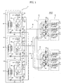
- Fig. 1 is a systemic view illustrating a multi-type air conditioner for simultaneous heating and cooling use according to a preferred embodiment of the present invention;
- Fig. 2 is a view illustrating withdrawal of refrigerant from a malfunctioning first outdoor unit of the multi-type air conditioner for simultaneous heating and cooling use according to the preferred embodiment of the present invention; and
- Fig. 3 is a flowchart illustrating a method for withdrawing refrigerant from the multi-type air conditioner for simultaneous heating and cooling use according to the preferred embodiment of the present invention.
- The multi-type air conditioner for simultaneous heating and cooling use according to one preferred embodiment of the present invention, as shown in Fig. 1, includes a plurality of
outdoor units 10, a plurality ofindoor units 20, adistributor 30, disposed between the pluraloutdoor units 10 and the pluralindoor units 20, to selectively guide refrigerant to the pluralindoor units 20 according to the operating mode, i.e. a cooling mode, a heating mode, or a cooling and heating mode, and a refrigerant withdrawing device for withdrawing the refrigerant from a malfunctioning outdoor unit among the pluraloutdoor units 10 to other outdoor units when replacing a part of the malfunctioning outdoor unit. - Here, the plural
outdoor units 10 include three outdoor units, i.e. first, second, and thirdoutdoor units outdoor units 10 including the threeoutdoor units - The first, second, and third
outdoor units third compressor units way valves third heat exchangers - Each of the first, second, and
third compressor units - The
first compressors pair 54 are connected to each other via acommon accumulator 63. Thesecond compressor pair 55 are connected to each other via a secondcommon accumulator 64. Thethird compressor pair 56 are connected to each other via a thirdcommon accumulator 65. - One side of each of the first, second, and
third compressor units compressor suction tubes indoor units third compressor units compressor discharge tubes third compressor units way valves - The first, second and third
compressor discharge tubes outdoor heat exchangers - The high-pressure refrigerant compressed by the first, second and
third compressor units indoor units 20 through the first, second and third bypasses 54c, 55c and 56c. - Discharging parts of the first, second, and third
outdoor heat exchangers exchanger discharge tubes outdoor heat exchangers - First, second and third outdoor heat
exchanger discharge valves exchanger discharge tubes - Only the plural
indoor units 20 including the first, second, third, fourth, fifth and sixthindoor units - Each of the first, second, third, fourth, fifth and sixth
indoor units indoor heat exchanger 77 and anelectronic expansion valve 78. - Moreover, the
distributor 30 includes afirst distributor 31 connected to the first, second and thirdindoor units second distributor 32 connected to fourth, fifth and sixthindoor units - Each of the first and
second distributors pressure refrigerant tube 80 for guiding high-pressure gaseous refrigerant discharged from the first, second andthird compressor units pressure refrigerant tube 90 guides refrigerant passing through the first, second, third, fourth, fifth and sixthindoor units liquid refrigerant tube 100 guides liquid refrigerant discharged from the first, second and thirdoutdoor heat exchangers pressure refrigerant tube 80 and the low-pressure refrigerant tube 90. - The high-
pressure refrigerant tube 80 is divided into first, second, third, fourth, fifth and sixth high-pressure refrigerant tubes indoor heat exchangers 77 of the first, second, third, fourth, fifth and sixthindoor units - The low-
pressure refrigerant tube 90 is divided into first, second, third, fourth, fifth and sixth low-pressure refrigerant tubes indoor heat exchangers 77 of the first, second, third, fourth, fifth and sixthindoor units compressor suction tubes - The
liquid refrigerant tube 100 includes is divided into first, second, third, fourth, fifth and sixthliquid refrigerant tubes electronic expansion valves 78 of the first, second, third, fourth, fifth and sixthindoor units outdoor heat exchangers - In the first
outdoor unit 51, thefirst bypass 54c is connected to the high-pressure refrigerant tube 80 by afirst service valve 111. The firstcompressor suction tube 54a is connected to the low-pressure refrigerant tube 90 by asecond service valve 112. The first outdoor heatexchanger discharge tube 60a is connected to theliquid refrigerant tube 100 by athird service valve 113. - In the second
outdoor unit 52, thesecond bypass 55c is connected to the high-pressure refrigerant tube 80 by a fourth service valve 114. The secondcompressor suction tube 55a is connected to the low-pressure refrigerant tube 90 by afifth service valve 115. The second outdoor heatexchanger discharge tube 61a is connected to theliquid refrigerant tube 100 by asixth service valve 116. - In the third
outdoor unit 53, thethird bypass 56c is connected to the high-pressure refrigerant tube 80 by aseventh service valve 117. The thirdcompressor suction tube 56a is connected to the low-pressurerefrigerant tube 90 by aneighth service valve 118. The third outdoor heatexchanger discharge tube 62a is connected to the liquidrefrigerant tube 100 by aninth service valve 119. - The valve device includes first, second, third, fourth, fifth and sixth high-
pressure valves pressure refrigerant tubes pressure valves pressure refrigerant tubes - The refrigerant withdrawing device includes a refrigerant withdrawing tubing for withdrawing refrigerant discharged from a compressor unit of a malfunctioning outdoor unit among the plural
outdoor units 10 to the other outdoor units, and an opening and closing valve means for opening and closing the refrigerant withdrawing tube. - The refrigerant withdrawing tubing includes a first
refrigerant withdrawing tube 121 for connecting the firstoutdoor unit 51 to the secondoutdoor unit 52, a secondrefrigerant withdrawing tube 122 for connecting the secondoutdoor unit 52 to the thirdoutdoor unit 53, and a thirdrefrigerant withdrawing tube 123 for connecting the thirdoutdoor unit 53 to the firstoutdoor unit 51. - The first
refrigerant withdrawing tube 121 connects thefirst bypass 54c to the secondcompressor suction tube 55a. The secondrefrigerant withdrawing tube 122 connects thesecond bypass 55c to the thirdcompressor suction tube 56a. The thirdrefrigerant withdrawing tube 123 connects thethird bypass 56c to the firstcompressor suction tube 54a. - The opening and closing valve means include a first opening and
closing valve 121a installed in the firstrefrigerant withdrawing tube 121, a second opening andclosing valve 122a installed in the secondrefrigerant withdrawing tube 121, and a third opening andclosing valve 123a installed in the thirdrefrigerant withdrawing tube 123. - The multi-type air conditioner according to this embodiment of the present invention is operated as follows.
- First, assuming that the
first compressor 54 of the firstoutdoor unit 51 malfunctions, as a first step (S1), the first, second andthird service valves outdoor unit 51 and theindoor units 20. - Then, the fourth service valve 114 installed in the second
outdoor unit 52 is closed to prevent refrigerant from entering the second outdoor unit 42. - After that, as a second step (S2), the first opening and
closing valve 121a installed in the firstrefrigerant withdrawing tube 121 is opened to open the firstrefrigerant withdrawing tube 121. - In a third step (S3), the
second compressor unit 55 of the secondoutdoor unit 52 is operated to pump down such that refrigerant in the firstoutdoor unit 51 is withdrawn to the secondoutdoor unit 52. - Therefore, all of the refrigerant in the first
outdoor unit 51 is withdrawn to the secondoutdoor unit 52 through the firstrefrigerant withdrawing tube 121. - When all of the refrigerant in the first
outdoor unit 51 has been withdrawn, in a fourth step (S4) the first opening andclosing valve 121a is closed to seal the firstrefrigerant withdrawing tube 121. - The fourth service valve 114 is then opened such that refrigerant can flow between the second
outdoor unit 52 and the indoor unit 20 (step S5). - Afterwards, in a sixth step (S6), the
first compressor unit 54 of the firstoutdoor unit 51 is replaced while the second and thirdoutdoor units - After the replacement of the compressor unit of the first
outdoor unit 51, vacuum is applied to the firstoutdoor unit 51 and the first, second andthird service valves outdoor unit 51. - Meanwhile, since the withdrawal of refrigerant when the second
outdoor unit 52 or the thirdoutdoor unit 53 malfunctions is similar to the withdrawal of refrigerant from the firstoutdoor unit 51, a description thereof will be omitted. - Since, when one of the plural
outdoor units 10 malfunctions, heating and/or cooling can be performed by continuing to drive the remainder of the plural outdoor units, the malfunctioning compressor unit can be replaced without interruption of heating and/or cooling. - The multi-type air conditioner for simultaneous heating and cooling use and the method for withdrawing refrigerant therefrom has the following advantages.
- According to the disclosed multi-type air conditioner for simultaneous heating and cooling use and the method for withdrawing refrigerant therefrom, the refrigerant withdrawing device is provided between the plural outdoor units, refrigerant in a malfunctioning outdoor unit is withdrawn to the other outdoor units and the other outdoor units are normally operated while the compressor unit of the malfunctioning outdoor unit among the plural outdoor units is replaced. Thus, the compressor can be replaced, and/or the outdoor unit repaired, without interruption of heating and/or cooling.
- Moreover, since there is no need to remove the entirety of the refrigerant from the system, time spent replacing the compressor is reduced and the replacement of the compressor is made more convenient. Thus, since loss of refrigerant is minimized, costs can be reduced.
- Although the preferred embodiments of the present invention have been disclosed for illustrative purposes, those skilled in the art will appreciate that various modifications, additions and substitutions are possible, without departing from the scope of the invention as disclosed in the accompanying claims.
Claims (11)
- An air conditioner comprising:a plurality of outdoor units (10) each including a compressor unit, a multi-way valve, and an outdoor heat exchanger;a plurality of indoor units (20) each including an indoor heat exchanger and an electronic expansion valve;a distributor (30) installed between the plural outdoor units (10) and the plural indoor units (20) to selectively guide refrigerant to the plural indoor units (20) according to operation of the air conditioner; anda refrigerant withdrawing means installed between the plural outdoor units (10) to enable withdrawal of refrigerant from one outdoor unit to the other outdoor units).
- The air conditioner as set forth in claim 1, wherein the refrigerant withdrawing device comprises:refrigerant withdrawing tubes (121, 122, and 123) for withdrawing the refrigerant discharged from the compressor unit of the one outdoor unit to the other outdoor unit(s); andopening and closing valves (121a, 122a, and 123a) for opening and closing the refrigerant withdrawing tubes (121, 122, and 123).
- The air conditioner as set forth in claim 2, wherein the compressor unit includes:one side to which a compressor suction tube (54a, 55a, and 56a), through which the refrigerant is drawn from the indoor units, is connected; andanother side to which a bypass (54c, 55c, and 56c) for bypassing the discharged refrigerant such that the refrigerant does not pass through the outdoor heat exchangers is connected.
- The air conditioner as set forth in claim 3, wherein the refrigerant withdrawing tubes (121, 122, and 123) connect the bypass of the malfunctioning outdoor unit to the compressor suction tube of the other outdoor units.
- The air conditioner as set forth in claim 4, wherein the distributor (30) comprises:a high-pressure refrigerant tube (80) for guiding high-pressure gas refrigerant discharged from the compressor unit to the indoor unit for performing a heating operation;a low-pressure refrigerant tube (90) for guiding refrigerant passing through the first, second, third, fourth, fifth and sixth indoor units (20) to a suction port of the compressor;a liquid refrigerant tube (100) for guiding liquid refrigerant discharged from the outdoor heat exchangers to the indoor units for performing cooling operation; anda valve device for selectively opening and closing the high-pressure refrigerant tube (80) and the low-pressure refrigerant tub (90).
- The air conditioner as set forth in claim 5, wherein the outdoor unit (10) further comprises outdoor discharge tube (60a, 61a, and 62a) for guiding the liquid refrigerant discharged from the outdoor heat exchangers.
- The air conditioner as set forth in claim 6, wherein the compressor suction tubes (54a, 55a, and 56a), the bypasses (54c, 55c, and 56c), and the outdoor heat exchanger discharge tubes (60a, 61a, and 62a) are respectively connected to the low-pressure refrigerant tube (90), the high-pressure refrigerant tube (80), and the liquid refrigerant tube (100) by service valves (111, 112, 113, 114, 115, 116, 117, 118 and 119).
- The air conditioner of claim 1 constructed and arranged as a multi-type air conditioner for simultaneous heating and cooling.
- A method for withdrawing refrigerant from a unit of an air conditioner, comprising:a first step of blocking the refrigerant flow to indoor units by closing a service valve installed in one outdoor unit among a plurality of outdoor units (10);a second step of opening an opening and closing valve installed in a refrigerant withdrawing tube of the one outdoor unit;a third step of operating compressor units of the other outdoor units to pump down to withdraw the refrigerant from the one outdoor unit to the other outdoor units; anda fourth step of closing the opening and closing valve once all of the refrigerant in the one outdoor unit is withdrawn, whereby the other outdoor units can be operated normally after refrigerant is withdrawn from the one outdoor unit.
- The method as set forth in claim 9, wherein the first step further comprises the sub-step of closing a service valve for connecting compressor suction tubes of the other outdoor units to the distributor (30).
- The method as set forth in claim 9, wherein the fourth step further comprises the sub-step of opening a service valve of the other outdoor units.
Applications Claiming Priority (1)
| Application Number | Priority Date | Filing Date | Title |
|---|---|---|---|
| KR1020040115321A KR100688171B1 (en) | 2004-12-29 | 2004-12-29 | Air conditioner and refrigerant recovery method |
Publications (1)
| Publication Number | Publication Date |
|---|---|
| EP1677055A1 true EP1677055A1 (en) | 2006-07-05 |
Family
ID=36190445
Family Applications (1)
| Application Number | Title | Priority Date | Filing Date |
|---|---|---|---|
| EP05258097A Withdrawn EP1677055A1 (en) | 2004-12-29 | 2005-12-29 | Multi-type air conditioner |
Country Status (4)
| Country | Link |
|---|---|
| US (1) | US20060162353A1 (en) |
| EP (1) | EP1677055A1 (en) |
| KR (1) | KR100688171B1 (en) |
| CN (1) | CN1796883A (en) |
Cited By (2)
| Publication number | Priority date | Publication date | Assignee | Title |
|---|---|---|---|---|
| EP2679933A4 (en) * | 2011-02-22 | 2014-07-30 | Hitachi Ltd | AIR CONDITIONING AND HOT WATER SUPPLY SYSTEM |
| EP2426438A3 (en) * | 2010-08-27 | 2014-07-30 | Mitsubishi Heavy Industries | Multi-unit air conditioning system |
Families Citing this family (25)
| Publication number | Priority date | Publication date | Assignee | Title |
|---|---|---|---|---|
| JP3963192B1 (en) * | 2006-03-10 | 2007-08-22 | ダイキン工業株式会社 | Air conditioner |
| KR101176482B1 (en) * | 2006-10-19 | 2012-08-22 | 엘지전자 주식회사 | Multi-air conditioner for heating and cooling operations at the same time |
| KR100833859B1 (en) * | 2006-12-14 | 2008-06-02 | 엘지전자 주식회사 | Air Conditioning System and Its Control Method |
| KR100830462B1 (en) * | 2006-12-22 | 2008-05-20 | 엘지전자 주식회사 | Air conditioning system |
| KR101376607B1 (en) * | 2007-02-01 | 2014-03-21 | 엘지전자 주식회사 | Unification management system and control method for multi-air conditioner |
| KR100803575B1 (en) * | 2007-02-02 | 2008-02-15 | 엘지전자 주식회사 | Multi-Air Conditioning Integrated Management System and Method |
| KR100896996B1 (en) | 2007-02-02 | 2009-05-14 | 엘지전자 주식회사 | Multi-Air Conditioning Integrated Management System and Method |
| KR20090000248A (en) * | 2007-02-07 | 2009-01-07 | 엘지전자 주식회사 | Integrated management display device and method of air conditioner |
| KR100854829B1 (en) * | 2007-02-13 | 2008-08-27 | 엘지전자 주식회사 | Air Conditioning System and Its Control Method |
| EP2476965B1 (en) * | 2009-09-10 | 2018-10-24 | Mitsubishi Electric Corporation | Air conditioning device |
| US8904812B2 (en) * | 2010-02-10 | 2014-12-09 | Mitsubishi Electric Corporation | Refrigeration cycle apparatus |
| JP5665981B2 (en) * | 2011-06-14 | 2015-02-04 | 三菱電機株式会社 | Air conditioner |
| KR101288745B1 (en) * | 2011-10-27 | 2013-07-23 | 엘지전자 주식회사 | Air conditioner |
| EP2899478A4 (en) * | 2012-09-21 | 2016-06-29 | Toshiba Carrier Corp | EXTERIOR UNIT OF MULTI-TYPE AIR CONDITIONING DEVICE |
| EP3150935B1 (en) * | 2014-05-30 | 2019-03-06 | Mitsubishi Electric Corporation | Air conditioner |
| JP6248878B2 (en) * | 2014-09-18 | 2017-12-20 | 株式会社富士通ゼネラル | Air conditioner |
| CN106796071B (en) * | 2014-10-01 | 2020-02-11 | 丹佛斯有限公司 | Method and system for estimating refrigerant charge loss in RVCS systems |
| JP6293647B2 (en) * | 2014-11-21 | 2018-03-14 | ヤンマー株式会社 | heat pump |
| KR101685846B1 (en) * | 2015-09-30 | 2016-12-20 | 엘지전자 주식회사 | An air conditioner |
| KR102436706B1 (en) * | 2018-01-19 | 2022-08-25 | 엘지전자 주식회사 | Method for controlling multi-type air conditioner |
| CN108709292A (en) * | 2018-04-28 | 2018-10-26 | 珠海格力电器股份有限公司 | Control method of refrigerant circulating system and air conditioner |
| CN109974169B (en) * | 2019-02-28 | 2021-02-19 | 浙江高翔工贸有限公司 | Double-working-medium air conditioner |
| CN110486915B (en) * | 2019-09-06 | 2021-02-26 | 珠海格力电器股份有限公司 | Refrigerant circulating system, control method thereof and air conditioning unit |
| CN114893900B (en) * | 2022-04-13 | 2023-11-17 | 青岛海信电子设备股份有限公司 | air conditioner |
| CN115183348B (en) * | 2022-07-08 | 2024-09-06 | 珠海格力电器股份有限公司 | Dual-system air conditioning unit and control method thereof |
Citations (5)
| Publication number | Priority date | Publication date | Assignee | Title |
|---|---|---|---|---|
| JPH04324075A (en) * | 1991-04-23 | 1992-11-13 | Sanyo Electric Co Ltd | Air conditioning apparatus |
| US5490399A (en) * | 1993-03-08 | 1996-02-13 | Daikin Industries, Ltd. | Refrigeration apparatus |
| EP0744581A2 (en) * | 1992-02-28 | 1996-11-27 | Sanyo Electric Co., Ltd. | Air-conditioning apparatus |
| JPH1163711A (en) * | 1997-08-25 | 1999-03-05 | Mitsubishi Electric Corp | Multi air conditioner |
| JP2000146345A (en) * | 1998-11-04 | 2000-05-26 | Daikin Ind Ltd | Refrigeration equipment |
Family Cites Families (21)
| Publication number | Priority date | Publication date | Assignee | Title |
|---|---|---|---|---|
| US4184661A (en) * | 1977-02-28 | 1980-01-22 | General Electric Company | Disconnectable coupling for a split system air conditioner |
| US4363222A (en) * | 1979-01-19 | 1982-12-14 | Robinair Manufacturing Corporation | Environmental protection refrigerant disposal and charging system |
| JP2557903B2 (en) * | 1987-09-10 | 1996-11-27 | 株式会社東芝 | Air conditioner |
| JP3060770B2 (en) * | 1993-02-26 | 2000-07-10 | ダイキン工業株式会社 | Refrigeration equipment |
| KR100343639B1 (en) * | 1994-06-29 | 2002-11-23 | 다이킨 고교 가부시키가이샤 | Fuel Oil Operation Control System of Air Conditioning System |
| JPH09287835A (en) * | 1996-04-18 | 1997-11-04 | Matsushita Refrig Co Ltd | Air conditioner |
| KR100452720B1 (en) * | 1998-04-30 | 2004-12-23 | 삼성전자주식회사 | Vacuum device for air conditioner having compressors, condensers, outdoor unit, and indoor units, and vacuum method thereof |
| KR100437803B1 (en) * | 2002-06-12 | 2004-06-30 | 엘지전자 주식회사 | Multi-type air conditioner for cooling/heating the same time and method for controlling the same |
| KR100447204B1 (en) * | 2002-08-22 | 2004-09-04 | 엘지전자 주식회사 | Multi-type air conditioner for cooling/heating the same time and method for controlling the same |
| KR100459184B1 (en) * | 2002-08-24 | 2004-12-03 | 엘지전자 주식회사 | Multi-type air conditioner for cooling/heating the same time |
| KR100459137B1 (en) * | 2002-08-24 | 2004-12-03 | 엘지전자 주식회사 | Multi-type air conditioner for cooling/heating the same time |
| KR100457569B1 (en) * | 2002-11-22 | 2004-11-18 | 엘지전자 주식회사 | a linear expansion valve's control method for a heat pump system |
| KR100499507B1 (en) * | 2003-01-13 | 2005-07-05 | 엘지전자 주식회사 | Multi type air conditioner |
| KR100499506B1 (en) * | 2003-01-13 | 2005-07-05 | 엘지전자 주식회사 | Multi type air conditioner |
| KR100504509B1 (en) * | 2003-01-16 | 2005-08-03 | 엘지전자 주식회사 | Multi-type air conditioner for cooling/heating the same time |
| JP2004263996A (en) | 2003-03-04 | 2004-09-24 | Toshiba Kyaria Kk | Air conditioner |
| JP4159409B2 (en) | 2003-05-27 | 2008-10-01 | 三洋電機株式会社 | Air conditioner |
| KR100717444B1 (en) * | 2003-10-20 | 2007-05-14 | 엘지전자 주식회사 | Multi air conditioner and air conditioner control method |
| KR100511288B1 (en) * | 2003-11-14 | 2005-08-31 | 엘지전자 주식회사 | Out door unit of air conditioner with four compressors |
| KR100539570B1 (en) * | 2004-01-27 | 2005-12-29 | 엘지전자 주식회사 | multi airconditioner |
| KR100561535B1 (en) * | 2004-05-25 | 2006-03-17 | 삼성전자주식회사 | Outdoor unit for multi air conditioning system |
-
2004
- 2004-12-29 KR KR1020040115321A patent/KR100688171B1/en not_active Expired - Fee Related
-
2005
- 2005-12-28 US US11/318,562 patent/US20060162353A1/en not_active Abandoned
- 2005-12-28 CN CNA2005100488088A patent/CN1796883A/en active Pending
- 2005-12-29 EP EP05258097A patent/EP1677055A1/en not_active Withdrawn
Patent Citations (5)
| Publication number | Priority date | Publication date | Assignee | Title |
|---|---|---|---|---|
| JPH04324075A (en) * | 1991-04-23 | 1992-11-13 | Sanyo Electric Co Ltd | Air conditioning apparatus |
| EP0744581A2 (en) * | 1992-02-28 | 1996-11-27 | Sanyo Electric Co., Ltd. | Air-conditioning apparatus |
| US5490399A (en) * | 1993-03-08 | 1996-02-13 | Daikin Industries, Ltd. | Refrigeration apparatus |
| JPH1163711A (en) * | 1997-08-25 | 1999-03-05 | Mitsubishi Electric Corp | Multi air conditioner |
| JP2000146345A (en) * | 1998-11-04 | 2000-05-26 | Daikin Ind Ltd | Refrigeration equipment |
Non-Patent Citations (3)
| Title |
|---|
| PATENT ABSTRACTS OF JAPAN vol. 017, no. 159 (M - 1389) 29 March 1993 (1993-03-29) * |
| PATENT ABSTRACTS OF JAPAN vol. 1999, no. 08 30 June 1999 (1999-06-30) * |
| PATENT ABSTRACTS OF JAPAN vol. 2000, no. 08 6 October 2000 (2000-10-06) * |
Cited By (2)
| Publication number | Priority date | Publication date | Assignee | Title |
|---|---|---|---|---|
| EP2426438A3 (en) * | 2010-08-27 | 2014-07-30 | Mitsubishi Heavy Industries | Multi-unit air conditioning system |
| EP2679933A4 (en) * | 2011-02-22 | 2014-07-30 | Hitachi Ltd | AIR CONDITIONING AND HOT WATER SUPPLY SYSTEM |
Also Published As
| Publication number | Publication date |
|---|---|
| KR20060075942A (en) | 2006-07-04 |
| US20060162353A1 (en) | 2006-07-27 |
| KR100688171B1 (en) | 2007-03-02 |
| CN1796883A (en) | 2006-07-05 |
Similar Documents
| Publication | Publication Date | Title |
|---|---|---|
| EP1677055A1 (en) | Multi-type air conditioner | |
| KR101282565B1 (en) | Multi-type air conditioner for cooling/heating the same time | |
| EP3450881B1 (en) | Air conditioner | |
| US9791193B2 (en) | Air conditioner and method of controlling the same | |
| EP2515053B1 (en) | Multi type air conditioner and operating method | |
| EP2354723A2 (en) | Refrigerant system | |
| EP1475585B1 (en) | Air conditioner | |
| EP1473526B1 (en) | Air conditioner and outdoor unit therefor | |
| EP2236957A2 (en) | Air conditioner | |
| CN114076346A (en) | Multi-split air conditioner | |
| KR101176482B1 (en) | Multi-air conditioner for heating and cooling operations at the same time | |
| US7257964B2 (en) | Air conditioner | |
| JP5186398B2 (en) | Air conditioner | |
| KR100688170B1 (en) | Heat Pump Air Conditioners | |
| EP2006618A1 (en) | Refrigeration device | |
| KR100624789B1 (en) | Air conditioner | |
| KR101218862B1 (en) | Multi-type air conditioner for cooling/heating the same time | |
| KR100504499B1 (en) | Multi-type air conditioner for cooling/heating the same time | |
| KR20060075024A (en) | Air Conditioning Synchronous Multi Air Conditioner | |
| KR100606274B1 (en) | Pressure Balancer of Air Conditioner with Multiple Compressors | |
| JP5595766B2 (en) | Refrigeration equipment | |
| KR100469288B1 (en) | Multi-type air conditioner for cooling/heating the same time | |
| KR20180117935A (en) | Multi-type air conditioner | |
| JPH05149644A (en) | Air-conditioner |
Legal Events
| Date | Code | Title | Description |
|---|---|---|---|
| PUAI | Public reference made under article 153(3) epc to a published international application that has entered the european phase |
Free format text: ORIGINAL CODE: 0009012 |
|
| 17P | Request for examination filed |
Effective date: 20060117 |
|
| AK | Designated contracting states |
Kind code of ref document: A1 Designated state(s): AT BE BG CH CY CZ DE DK EE ES FI FR GB GR HU IE IS IT LI LT LU LV MC NL PL PT RO SE SI SK TR |
|
| AX | Request for extension of the european patent |
Extension state: AL BA HR MK YU |
|
| 17Q | First examination report despatched |
Effective date: 20070115 |
|
| AKX | Designation fees paid |
Designated state(s): DE FR GB IT |
|
| STAA | Information on the status of an ep patent application or granted ep patent |
Free format text: STATUS: THE APPLICATION IS DEEMED TO BE WITHDRAWN |
|
| 18D | Application deemed to be withdrawn |
Effective date: 20161011 |