EP1676965A2 - Boom-holding control device for use in heavy construction equipments - Google Patents
Boom-holding control device for use in heavy construction equipments Download PDFInfo
- Publication number
- EP1676965A2 EP1676965A2 EP05292736A EP05292736A EP1676965A2 EP 1676965 A2 EP1676965 A2 EP 1676965A2 EP 05292736 A EP05292736 A EP 05292736A EP 05292736 A EP05292736 A EP 05292736A EP 1676965 A2 EP1676965 A2 EP 1676965A2
- Authority
- EP
- European Patent Office
- Prior art keywords
- boom
- travel
- valve
- release
- holding
- Prior art date
- Legal status (The legal status is an assumption and is not a legal conclusion. Google has not performed a legal analysis and makes no representation as to the accuracy of the status listed.)
- Withdrawn
Links
- 238000010276 construction Methods 0.000 title claims description 9
- 239000012530 fluid Substances 0.000 claims abstract description 36
- 230000004044 response Effects 0.000 claims abstract description 9
- 230000000903 blocking effect Effects 0.000 claims abstract description 8
- 230000004913 activation Effects 0.000 claims abstract description 3
- 230000009471 action Effects 0.000 description 6
- 238000010586 diagram Methods 0.000 description 5
- 238000004891 communication Methods 0.000 description 4
- 230000003213 activating effect Effects 0.000 description 3
- 230000006378 damage Effects 0.000 description 2
- 238000000034 method Methods 0.000 description 2
- 230000009286 beneficial effect Effects 0.000 description 1
- 230000006835 compression Effects 0.000 description 1
- 238000007906 compression Methods 0.000 description 1
- 230000001788 irregular Effects 0.000 description 1
- 238000012986 modification Methods 0.000 description 1
- 230000004048 modification Effects 0.000 description 1
- 230000003534 oscillatory effect Effects 0.000 description 1
- 230000008569 process Effects 0.000 description 1
- 230000009528 severe injury Effects 0.000 description 1
- 230000035939 shock Effects 0.000 description 1
Images



Classifications
-
- E—FIXED CONSTRUCTIONS
- E02—HYDRAULIC ENGINEERING; FOUNDATIONS; SOIL SHIFTING
- E02F—DREDGING; SOIL-SHIFTING
- E02F9/00—Component parts of dredgers or soil-shifting machines, not restricted to one of the kinds covered by groups E02F3/00 - E02F7/00
- E02F9/20—Drives; Control devices
- E02F9/22—Hydraulic or pneumatic drives
- E02F9/2278—Hydraulic circuits
- E02F9/2292—Systems with two or more pumps
-
- E—FIXED CONSTRUCTIONS
- E02—HYDRAULIC ENGINEERING; FOUNDATIONS; SOIL SHIFTING
- E02F—DREDGING; SOIL-SHIFTING
- E02F9/00—Component parts of dredgers or soil-shifting machines, not restricted to one of the kinds covered by groups E02F3/00 - E02F7/00
- E02F9/20—Drives; Control devices
-
- E—FIXED CONSTRUCTIONS
- E02—HYDRAULIC ENGINEERING; FOUNDATIONS; SOIL SHIFTING
- E02F—DREDGING; SOIL-SHIFTING
- E02F9/00—Component parts of dredgers or soil-shifting machines, not restricted to one of the kinds covered by groups E02F3/00 - E02F7/00
- E02F9/20—Drives; Control devices
- E02F9/22—Hydraulic or pneumatic drives
-
- E—FIXED CONSTRUCTIONS
- E02—HYDRAULIC ENGINEERING; FOUNDATIONS; SOIL SHIFTING
- E02F—DREDGING; SOIL-SHIFTING
- E02F9/00—Component parts of dredgers or soil-shifting machines, not restricted to one of the kinds covered by groups E02F3/00 - E02F7/00
- E02F9/20—Drives; Control devices
- E02F9/22—Hydraulic or pneumatic drives
- E02F9/226—Safety arrangements, e.g. hydraulic driven fans, preventing cavitation, leakage, overheating
-
- E—FIXED CONSTRUCTIONS
- E02—HYDRAULIC ENGINEERING; FOUNDATIONS; SOIL SHIFTING
- E02F—DREDGING; SOIL-SHIFTING
- E02F9/00—Component parts of dredgers or soil-shifting machines, not restricted to one of the kinds covered by groups E02F3/00 - E02F7/00
- E02F9/20—Drives; Control devices
- E02F9/22—Hydraulic or pneumatic drives
- E02F9/2278—Hydraulic circuits
- E02F9/2285—Pilot-operated systems
-
- E—FIXED CONSTRUCTIONS
- E02—HYDRAULIC ENGINEERING; FOUNDATIONS; SOIL SHIFTING
- E02F—DREDGING; SOIL-SHIFTING
- E02F9/00—Component parts of dredgers or soil-shifting machines, not restricted to one of the kinds covered by groups E02F3/00 - E02F7/00
- E02F9/20—Drives; Control devices
- E02F9/22—Hydraulic or pneumatic drives
- E02F9/2278—Hydraulic circuits
- E02F9/2296—Systems with a variable displacement pump
-
- F—MECHANICAL ENGINEERING; LIGHTING; HEATING; WEAPONS; BLASTING
- F15—FLUID-PRESSURE ACTUATORS; HYDRAULICS OR PNEUMATICS IN GENERAL
- F15B—SYSTEMS ACTING BY MEANS OF FLUIDS IN GENERAL; FLUID-PRESSURE ACTUATORS, e.g. SERVOMOTORS; DETAILS OF FLUID-PRESSURE SYSTEMS, NOT OTHERWISE PROVIDED FOR
- F15B2211/00—Circuits for servomotor systems
- F15B2211/20—Fluid pressure source, e.g. accumulator or variable axial piston pump
- F15B2211/205—Systems with pumps
- F15B2211/2053—Type of pump
- F15B2211/20546—Type of pump variable capacity
-
- F—MECHANICAL ENGINEERING; LIGHTING; HEATING; WEAPONS; BLASTING
- F15—FLUID-PRESSURE ACTUATORS; HYDRAULICS OR PNEUMATICS IN GENERAL
- F15B—SYSTEMS ACTING BY MEANS OF FLUIDS IN GENERAL; FLUID-PRESSURE ACTUATORS, e.g. SERVOMOTORS; DETAILS OF FLUID-PRESSURE SYSTEMS, NOT OTHERWISE PROVIDED FOR
- F15B2211/00—Circuits for servomotor systems
- F15B2211/30—Directional control
- F15B2211/305—Directional control characterised by the type of valves
- F15B2211/30525—Directional control valves, e.g. 4/3-directional control valve
-
- F—MECHANICAL ENGINEERING; LIGHTING; HEATING; WEAPONS; BLASTING
- F15—FLUID-PRESSURE ACTUATORS; HYDRAULICS OR PNEUMATICS IN GENERAL
- F15B—SYSTEMS ACTING BY MEANS OF FLUIDS IN GENERAL; FLUID-PRESSURE ACTUATORS, e.g. SERVOMOTORS; DETAILS OF FLUID-PRESSURE SYSTEMS, NOT OTHERWISE PROVIDED FOR
- F15B2211/00—Circuits for servomotor systems
- F15B2211/30—Directional control
- F15B2211/31—Directional control characterised by the positions of the valve element
- F15B2211/3105—Neutral or centre positions
- F15B2211/3116—Neutral or centre positions the pump port being open in the centre position, e.g. so-called open centre
-
- F—MECHANICAL ENGINEERING; LIGHTING; HEATING; WEAPONS; BLASTING
- F15—FLUID-PRESSURE ACTUATORS; HYDRAULICS OR PNEUMATICS IN GENERAL
- F15B—SYSTEMS ACTING BY MEANS OF FLUIDS IN GENERAL; FLUID-PRESSURE ACTUATORS, e.g. SERVOMOTORS; DETAILS OF FLUID-PRESSURE SYSTEMS, NOT OTHERWISE PROVIDED FOR
- F15B2211/00—Circuits for servomotor systems
- F15B2211/30—Directional control
- F15B2211/31—Directional control characterised by the positions of the valve element
- F15B2211/3144—Directional control characterised by the positions of the valve element the positions being continuously variable, e.g. as realised by proportional valves
-
- F—MECHANICAL ENGINEERING; LIGHTING; HEATING; WEAPONS; BLASTING
- F15—FLUID-PRESSURE ACTUATORS; HYDRAULICS OR PNEUMATICS IN GENERAL
- F15B—SYSTEMS ACTING BY MEANS OF FLUIDS IN GENERAL; FLUID-PRESSURE ACTUATORS, e.g. SERVOMOTORS; DETAILS OF FLUID-PRESSURE SYSTEMS, NOT OTHERWISE PROVIDED FOR
- F15B2211/00—Circuits for servomotor systems
- F15B2211/30—Directional control
- F15B2211/32—Directional control characterised by the type of actuation
- F15B2211/329—Directional control characterised by the type of actuation actuated by fluid pressure
-
- F—MECHANICAL ENGINEERING; LIGHTING; HEATING; WEAPONS; BLASTING
- F15—FLUID-PRESSURE ACTUATORS; HYDRAULICS OR PNEUMATICS IN GENERAL
- F15B—SYSTEMS ACTING BY MEANS OF FLUIDS IN GENERAL; FLUID-PRESSURE ACTUATORS, e.g. SERVOMOTORS; DETAILS OF FLUID-PRESSURE SYSTEMS, NOT OTHERWISE PROVIDED FOR
- F15B2211/00—Circuits for servomotor systems
- F15B2211/70—Output members, e.g. hydraulic motors or cylinders or control therefor
- F15B2211/765—Control of position or angle of the output member
- F15B2211/7653—Control of position or angle of the output member at distinct positions, e.g. at the end position
-
- F—MECHANICAL ENGINEERING; LIGHTING; HEATING; WEAPONS; BLASTING
- F15—FLUID-PRESSURE ACTUATORS; HYDRAULICS OR PNEUMATICS IN GENERAL
- F15B—SYSTEMS ACTING BY MEANS OF FLUIDS IN GENERAL; FLUID-PRESSURE ACTUATORS, e.g. SERVOMOTORS; DETAILS OF FLUID-PRESSURE SYSTEMS, NOT OTHERWISE PROVIDED FOR
- F15B2211/00—Circuits for servomotor systems
- F15B2211/80—Other types of control related to particular problems or conditions
- F15B2211/86—Control during or prevention of abnormal conditions
- F15B2211/8606—Control during or prevention of abnormal conditions the abnormal condition being a shock
-
- F—MECHANICAL ENGINEERING; LIGHTING; HEATING; WEAPONS; BLASTING
- F15—FLUID-PRESSURE ACTUATORS; HYDRAULICS OR PNEUMATICS IN GENERAL
- F15B—SYSTEMS ACTING BY MEANS OF FLUIDS IN GENERAL; FLUID-PRESSURE ACTUATORS, e.g. SERVOMOTORS; DETAILS OF FLUID-PRESSURE SYSTEMS, NOT OTHERWISE PROVIDED FOR
- F15B2211/00—Circuits for servomotor systems
- F15B2211/80—Other types of control related to particular problems or conditions
- F15B2211/86—Control during or prevention of abnormal conditions
- F15B2211/8613—Control during or prevention of abnormal conditions the abnormal condition being oscillations
Definitions
- the present invention is directed to a boom-holding control device for use in heavy construction equipments and more specifically to a boom-holding control device that prevents inertia-caused in-travel raising movement and gravity-caused in-work lowering movement of a boom in heavy construction equipments such as an excavator and the like.
- the boom may be unintentionally lowered under the action of its own weight or the weight of loads carried by a bucket.
- the conventional hydraulic excavator is provided with a boom holding valve.
- the prior art boom control device includes a main fluid pump P1 and an auxiliary pump P2, each of which generates a pressurized hydraulic flow.
- the hydraulic flow discharged from the main pump P1 is supplied to hydraulic actuators such as a boom cylinder 13, a travel motor (not shown) and the like under a control of a plurality of control spools, including a boom control spool 11 and a travel control spool 12, incorporated in a control valve 10.
- a remote control valve 20 applies a boom-up pilot signal pressure (P up ) to one pressure receiving part, the boom control spool 11 of the control valve 10 is shifted in one direction to allow the hydraulic flow of the main fluid pump P1 to enter the piston-side chamber 13a of the boom cylinder 13 to thereby raise up the boom.
- the remote control valve 20 applies a boom-down pilot signal pressure (P dn ) to the other pressure receiving part, the boom control spool 11 of the control valve 10 is shifted in the opposite direction to allow the hydraulic flow of the main fluid pump P1 to enter the rod-side chamber 13b of the boom cylinder 13 to thereby lower down the boom.
- a boom holding valve 15 is connected to a fluid pressure line 14 that interconnects the boom control spool 11 and the piston-side chamber 13a of the boom cylinder 13.
- the boom holding valve 15 includes a poppet 17 slidably fitted into an interior space of the valve in such a manner that the poppet 17 can divide the interior space into a front pressure receiving chamber 15a, a lateral pressure receiving chamber 15b and a rear pressure receiving chamber 15c.
- a spring 16 is provided on the rear side of the poppet 17 to resiliently bias the poppet 17 toward a position where the front pressure receiving chamber 15a is disconnected from the lateral pressure receiving chamber 15b.
- the front pressure receiving chamber 15a is in communication with the boom control spool 11 via the fluid pressure line 14 and the rear pressure receiving chamber 15c is led to a fluid tank T by way of a boom release valve 19.
- the lateral pressure receiving chamber 15b is in communication with the rear pressure receiving chamber 15c through a built-in flow passage 17a and also communicates with the piston-side chamber 13a of the boom cylinder 13 via the fluid pressure line 14.
- the boom release valve 19 has a pressure receiving part 19a coupled to the remote control valve 20 through a pilot signal line 21 for reception of the boom-down pilot signal pressure Pdn from the remote control valve 20.
- the pressure receiving part 19a of the boom release valve 19 is also coupled to a travel pedal valve 22 through travel signal lines 23, 24 for reception of a travel signal pressure from the travel pedal valve 22.
- Reference numeral 25 designates a changeover valve for selectively opening and closing the travel signal line 24 and reference numeral 26 designates a travel selection switch for shifting the position of the changeover valve 25.
- the boom release valve 19 moves into a drain position where the rear pressure receiving chamber 15c communicates with the fluid tank T to thereby release the boom from a holding condition. If, however, neither the boom-down pilot signal pressure (P dn ) nor the travel signal pressure is exerted on the pressure receiving part 19a of the boom release valve 19, the boom release valve 19 is returned back to a shutoff position, by the action of a spring 19b, where the rear pressure receiving chamber 15c is disconnected from the fluid tank T to thereby bring the boom into the holding condition.
- the boom release valve 19 keeps the boom against raising movement while the excavator travels.
- the boom holding valve 15 remains opened so that the fluid can be drained from the rod-side chamber 13a of the boom cylinder 13 through the fluid pressure line 14.
- the weight of the boom is supported by a bucket that has been retracted toward and placed on a frontal part of an excavator body.
- the excavator runs over an irregular ground surface and is shaken by the vibration imparted to the excavator body, the bucket is repeatedly bumped against the excavator body, which applies a great deal of oscillatory shock to a buck cylinder particularly during the course of long distance travel of the excavator. This may cause severe damage to the bucket cylinder.
- the operator should periodically raise up the boom during traveling to reduce the load of the boom acting on the bucket. Needless to say, this makes the operator feel cumbersome.
- the present invention aims at providing a boom-holding control device that can prevent a bucket from receiving excessive loads by the weight of a boom in the course of travel of an excavator, while enabling an operator to release the boom from a holding condition and to lower down the boom into a desired rest position through a simple manipulation without having to stop the travel movement of the excavator, in case that the boom has been unintentionally moved up by in-travel joggling of the excavator.
- a boom-holding control device for use in heavy construction equipments, comprising: a boom-holding valve provided on a fluid pressure line interconnecting a boom control spool and a piston-side chamber of a boom cylinder for preventing boom deadweight-caused drainage of a hydraulic flow from the piston-side chamber to thereby keep a boom in a holding condition; a boom release valve for releasing the boom from the holding condition in response to at least one of a boom-down pilot signal pressure supplied from a boom cylinder remote control valve and a travel signal pressure fed from a travel control operator-interface device; a solenoid-actuated changeover valve provided on a travel signal line interconnecting the travel control device and a pressure receiving part of the boom-holding valve for selectively opening and blocking off the travel signal line; a travel selection switch for issuing electric travel signals when activated to assume a travel position; and a boom release switch for generating electric boom release signals when activated to assume a boom release position, wherein the solenoi
- boom-holding control device further comprise a controller for shifting the solenoid-actuated changeover valve into the opening position when the electric travel signals and the electric boom release signals are concurrently inputted from the travel selection switch and the boom release switch.
- the controller be adapted to cyclically keep the solenoid-actuated changeover valve in the opening position for a predetermined time period at a predetermined interval when the electric travel signals and the electric boom release signals are concurrently inputted from the travel selection switch and the boom release switch.
- the controller has a time selection means for selecting the predetermined time period during which the changeover valve remains in the opening position by the controller.
- a boom-holding control device for use in heavy construction equipments, comprising: a boom-holding valve provided on a fluid pressure line interconnecting a boom control spool and a piston-side chamber of a boom cylinder for preventing boom deadweight-caused drainage of a hydraulic flow from the piston-side chamber to thereby keep a boom in a holding condition; a boom release valve for releasing the boom from the holding condition in response to at least one of a boom-down pilot signal pressure supplied from a boom cylinder remote control valve and a travel signal pressure fed from a travel control operator-interface device; a solenoid-actuated changeover valve provided on a travel signal line interconnecting the travel control device and a pressure receiving part of the boom-holding valve for selectively opening and blocking off the travel signal line; a travel selection switch for issuing electric travel signals when activated to assume a travel position; and a controller for cyclically keeping the solenoid-actuated changeover valve in an opening position for a predetermined time
- a boom-holding control device for use in heavy construction equipments, comprising: a boom-holding valve provided on a fluid pressure line interconnecting a boom control spool and a piston-side chamber of a boom cylinder for preventing boom deadweight-caused drainage of a hydraulic flow from the piston-side chamber to thereby keep a boom in a holding condition; a boom release valve for releasing the boom from the holding condition in response to at least one of a boom-down pilot signal pressure supplied from a boom cylinder remote control valve and a travel signal pressure fed from a travel control operator-interface device; a solenoid-actuated changeover valve provided on a travel signal line interconnecting the travel control device and a pressure receiving part of the boom-holding valve for selectively opening and blocking off the travel signal line; a travel selection switch for issuing electric travel signals when activated to assume a travel position; a boom release switch for generating electric boom release signals when activated to assume a boom release position; a controller including
- the boom-holding control device of the present invention as summarized above provides a beneficial effect in that, when a boom has been unintentionally raised up in the course of travel of an excavator, the boom can be released from a holding condition and lowered down to a desired rest position by turning on a boom release switch without having to stop traveling movement of the excavator. At this time, the boom is released from the holding condition for a predetermined time period under the control of an electric controller and then returned back to the holding condition in an automated fashion. This prevents a bucket supported on an excavator body from receiving an excessive depression force by the deadweight of the boom, thereby keeping the bucket against damage.
- FIG. 2 is a fluid pressure circuit diagram showing one embodiment of a boom-holding control device in accordance with the present invention, which is applied to a wheel-type hydraulic excavator.
- the boom-holding control device comprises a main fluid pump P and an auxiliary pump P2, each generating hydraulic flow for actuation of various hydraulic actuators.
- the hydraulic flow discharged from the main fluid pump P 1 is supplied to a boom cylinder 13 and a travel motor (not shown) under the control of a boom control spool 11 and a travel control spool 12 incorporated in a control valve 10.
- the boom control spool 11 of the control valve 10 is position-controlled by pilot signal pressures (P up , P dn ) issuing from a remote control valve 20, whereas the travel control spool 12 of the control valve 10 is position-controlled by travel signal pressures (P tr , P tl ) issuing from a travel selection valve 32.
- boom-up pilot signal pressure (P up ) generated in the remote control valve 20 is exerted on one pressure receiving part of the boom control spool 11, the boom control spool 11 is shifted to the right in FIG. 2, thus allowing the hydraulic flow of the main fluid pump P1 to be supplied to the piston-side chamber 13a of the boom cylinder 13 to thereby raise up the boom.
- the boom-down pilot signal pressure (P dn ) generated in the remote control valve 20 is exerted on the other pressure receiving part of the boom control spool 11, the boom control spool 11 is shifted to the left in FIG. 2, thus permitting the hydraulic flow of the main fluid pump P1 to be supplied to the rod-side chamber 13b of the boom cylinder 13 to thereby lower down the boom.
- a boom-holding valve 15 is provided on the fluid pressure line 14 that interconnects the boom control spool 11 and the piston-side chamber 13a of the boom cylinder 13.
- the boom-holding valve 15 includes a poppet 17 slidably inserted into the interior space of a valve body and normally biased forward by means of a compression spring 16 mounted at the rear side of the poppet 17, thus keeping the boom in a holding condition.
- the poppet 17 divides the interior space of the valve body into a front pressure receiving chamber 15a, a lateral pressure receiving chamber 15b and a rear pressure receiving chamber 15c, and is resiliently urged by the spring 16 toward a position where the front pressure receiving chamber 15a is disconnected from the lateral pressure receiving chamber 15b.
- the front pressure receiving chamber 15a is in communication with the boom control spool 11 via the fluid pressure line 14.
- the lateral pressure receiving chamber 15b is in communication with the rear pressure receiving chamber 15c through a built-in flow passage 17a of the poppet 17 and also communicates with the piston-side chamber 13a of the boom cylinder 13 via the fluid pressure line 14.
- the rear pressure receiving chamber 15c is led to a fluid tank T by way of a boom release valve 19.
- the boom release valve 19 has a pressure receiving part 19a connected to a boom release signal supplying means noted below and is normally kept in a shutoff position by the biasing force of a spring 19b. Responsive to a boom release signal pressure from the boom release signal supplying means, the boom release valve 19 shifted to a drain position where the fluid in the rear pressure receiving chamber 15c of the boom-holding valve 15 is drained to the fluid tank T. This allows the poppet 17 of the boom-holding valve 15 to move backward so that the hydraulic flow in the piston-side chamber 13a of the boom cylinder 13 can be drained through the fluid pressure line 14, thereby releasing the boom from a holding condition.
- the boom release signal supplying means comprises a shuttle valve 18 that acts to supply the boom release valve 19 with one of the boom-down pilot signal pressure (P dn ) received from the remote control valve 20 and the travel signal pressure delivered through a travel signal line 24 which is bifurcated from a travel pilot signal line 23 interconnecting a travel pedal valve 22 and a travel selection valve 32.
- the boom release valve 19 moves into the drain position where the rear pressure receiving chamber 15c communicates with the fluid tank T. This allows the poppet 17 of the boom-holding valve 15 to move backward, thereby releasing the boom from the holding condition. If, however, neither the boom-down pilot signal pressure (P dn ) nor the travel signal pressure is exerted on the pressure receiving part 19a of the boom release valve 19, the boom release valve 19 is returned back to the shutoff position, by the action of the spring 19b, where the rear pressure receiving chamber 15c is disconnected from the fluid tank T. This permits the poppet 17 of the boom-holding valve 15 to move forward, thereby bringing the boom into the holding condition.
- a solenoid-actuated changeover valve 25 is provided on the travel signal line 24 for selectively opening and blocking off the travel signal line 24.
- the solenoid-actuated changeover valve 25 is shifted to an opening position 25b to open the travel signal line 24 if an electric controller 30 applies electric signals to a solenoid part 25a of the changeover valve 25, but is returned back to a closing position 25c to block off the travel signal line 24 and to eliminate the travel signal pressure from the shuttle valve 18 if the controller 30 applies no electric signal to the solenoid part 25a of the changeover valve 25.
- the controller 30 is adapted to apply the electric signals to the solenoid part 25a of changeover valve 25 to thereby shift the changeover valve 25 into the opening position 25b, thus releasing the boom from the holding condition, when an electric travel signals (I t ) and an electric boom release signals (I hd ) are concurrently inputted from a travel selection switch 26 and a boom release switch 28. If no electric boom release signal (I hd ) is supplied to the controller 30, the controller 30 applies no electric signal to the solenoid part 25a of changeover valve 25 to thereby keep the changeover valve 25 in the closing position 25c, thus maintaining the boom at the holding condition.
- the boom-holding control device is adapted to keep the boom in the holding condition during the course of travel of the excavator. This makes it possible to prevent the bucket from bearing excessive loads by the deadweight of the boom.
- the controller 30 issues electric signals to the changeover valve 25, in response to which the changeover valve 25 opens the travel signal line 24 to allow the travel signal pressure to be delivered to the shuttle valve 18.
- the boom release signal pressure is applied to the boom release valve 19 through the travel signal line 24 and therefore the boom is released from the holding condition, making it possible to lower down the boom.
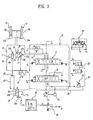
- FIG. 3 shows another embodiment of a boom-holding control device in accordance with the present invention, in which embodiment the boom holding and releasing operations are automatically performed at a predetermined time interval.
- the following description will be centered on those parts that differ from the preceding embodiment and the same parts will not be described for the sake of simplicity.
- the controller 30 is connected to the solenoid part 25a of the changeover valve 25 so that it can supply the solenoid part 25a with electric signals to shift the changeover valve 25 to the opening position 25b. If the travel selection switch 26 is activated to assume a travel position TR, it generates and inputs electric travel signals It to the controller 30. In response, the controller 30 repeatedly applies electric signals to the solenoid part 25a of the changeover valve 25 for a predetermined time period (t) at a predetermined interval ( ⁇ t).
- the controller 30 applies the electric signals to the solenoid part 25a of the changeover valve 25 for a predetermined time period (t) at a predetermined interval ( ⁇ t) so that the changeover valve 25 can be repeatedly shifted between the opening position 25b and the closing position 25c. Accordingly, the boom holding condition and the boom release condition are repeatedly switched over in an automated manner.
- FIG. 4 shows a further embodiment of a boom-holding control device in accordance with the present invention.
- the boom-holding control device has an automatic mode under which the boom holding and releasing operations are automatically performed at a predetermined time interval and a manual mode under which the boom is released from the holding condition only when the operator selects that mode. Mode selection is made by the operator.
- the following description will be centered on those parts that differ from the embodiment as shown in FIG. 2 and the same parts will not be described for the sake of simplicity.
- the solenoid-actuated changeover valve 25 is provided on the travel signal line 24 that interconnects the travel pedal valve 22 and the pressure receiving part 19a of the boom release valve 19.
- the changeover valve 25 is shiftable between the opening position 25b where the travel signal line 24 is opened by the changeover valve 25 and the closing position 25c where the changeover valve 25 blocks off the travel signal line 24.
- the changeover valve 25 is normally kept in the closing position 25c and will be shifted to the opening position 25b to open the travel signal line 24 in case that the controller 30 applies electric signals to the solenoid part 25a.
- the controller 30 includes an automatic mode part 30A for supplying electric signals to the solenoid part 25a of the changeover valve 25 to cyclically maintain the changeover valve 25 in the opening position 25b for a predetermined time period (t) at a predetermined interval ( ⁇ t) when the electric travel signals (I t ) and the electric boom release signals (I hd ) are concurrently inputted from the travel selection switch 26 and the boom release switch 28 by activating the switches 26, 28 into the travel position TR and the release position R, respectively, and a manual mode part 30B for supplying electric signals to the solenoid part 25a of the changeover valve 25 to continuously keep the changeover valve 25 in the opening position 25b for a predetermined time period (t) when the electric travel signals (I t ) and the electric boom release signals (I hd ) are concurrently inputted from the travel selection switch 26 and the boom release switch 28 by activating the switches 26, 28 into the travel position TR and the release position R, respectively.
- a mode selection switch 31 for allowing
- the boom-holding control device is operable either in an automatic mode that automatically repeats the boom holding and the boom release operations or in a manual mode that keeps the boom released only when the operator makes selection of the manual mode.
- the mode selection switch 31 enables the operator to select one of the automatic mode and the manual mode.
- a time selection means (not shown) is connected to the controller 30 for variably selecting the time period (t) that the controller 30 issues the electric signals.
- the time selection means may be a dial switch or other suitable means and may preferably be provided in a cabin for the operator to manipulate it during the course of driving the excavator.
- a boom can be released from a holding condition automatically or manually in the course of travel of the excavator. This helps to prevent the boom from moving upward by a making-up action during the travel process of the excavator which would otherwise mar the visibility of an operator and increase the overall height of the excavator.
Landscapes
- Engineering & Computer Science (AREA)
- Mining & Mineral Resources (AREA)
- Civil Engineering (AREA)
- General Engineering & Computer Science (AREA)
- Structural Engineering (AREA)
- Operation Control Of Excavators (AREA)
Abstract
Description
- The present invention is directed to a boom-holding control device for use in heavy construction equipments and more specifically to a boom-holding control device that prevents inertia-caused in-travel raising movement and gravity-caused in-work lowering movement of a boom in heavy construction equipments such as an excavator and the like.
- In the event that a hydraulic excavator stops its operations with a boom raised up, the boom may be unintentionally lowered under the action of its own weight or the weight of loads carried by a bucket. For the purpose of avoiding such boom lowering phenomenon, the conventional hydraulic excavator is provided with a boom holding valve.
- By the way, during the course of travel of the hydraulic excavator, the boom often tends to be shaken up and down by virtue of the joggling of an excavator body, at which time the boom is raised up little by little owing to the self-making-up action of the boom holding valve. The boom thus raised may sometimes mar the visibility of an operator and may become an obstacle in passing through overhead road structures, in which case the operator should stop driving the excavator in an effort to lower down the boom into the original position. In view of such inconvenience, there has been proposed a boom control device of the type as illustrated in FIG. 1.
- As can be seen in FIG. 1, the prior art boom control device includes a main fluid pump P1 and an auxiliary pump P2, each of which generates a pressurized hydraulic flow. The hydraulic flow discharged from the main pump P1 is supplied to hydraulic actuators such as a
boom cylinder 13, a travel motor (not shown) and the like under a control of a plurality of control spools, including aboom control spool 11 and atravel control spool 12, incorporated in acontrol valve 10. If aremote control valve 20 applies a boom-up pilot signal pressure (Pup) to one pressure receiving part, theboom control spool 11 of thecontrol valve 10 is shifted in one direction to allow the hydraulic flow of the main fluid pump P1 to enter the piston-side chamber 13a of theboom cylinder 13 to thereby raise up the boom. To the contrary, if theremote control valve 20 applies a boom-down pilot signal pressure (Pdn) to the other pressure receiving part, theboom control spool 11 of thecontrol valve 10 is shifted in the opposite direction to allow the hydraulic flow of the main fluid pump P1 to enter the rod-side chamber 13b of theboom cylinder 13 to thereby lower down the boom. - A
boom holding valve 15 is connected to afluid pressure line 14 that interconnects theboom control spool 11 and the piston-side chamber 13a of theboom cylinder 13. Theboom holding valve 15 includes apoppet 17 slidably fitted into an interior space of the valve in such a manner that thepoppet 17 can divide the interior space into a frontpressure receiving chamber 15a, a lateralpressure receiving chamber 15b and a rearpressure receiving chamber 15c. Aspring 16 is provided on the rear side of thepoppet 17 to resiliently bias thepoppet 17 toward a position where the frontpressure receiving chamber 15a is disconnected from the lateralpressure receiving chamber 15b. The frontpressure receiving chamber 15a is in communication with theboom control spool 11 via thefluid pressure line 14 and the rearpressure receiving chamber 15c is led to a fluid tank T by way of aboom release valve 19. The lateralpressure receiving chamber 15b is in communication with the rearpressure receiving chamber 15c through a built-inflow passage 17a and also communicates with the piston-side chamber 13a of theboom cylinder 13 via thefluid pressure line 14. - The
boom release valve 19 has apressure receiving part 19a coupled to theremote control valve 20 through apilot signal line 21 for reception of the boom-down pilot signal pressure Pdn from theremote control valve 20. Thepressure receiving part 19a of theboom release valve 19 is also coupled to atravel pedal valve 22 throughtravel signal lines travel pedal valve 22.Reference numeral 25 designates a changeover valve for selectively opening and closing thetravel signal line 24 andreference numeral 26 designates a travel selection switch for shifting the position of thechangeover valve 25. - If one of the boom-down pilot signal pressure (Pdn) and the travel signal pressure is exerted on the
pressure receiving part 19a of theboom release valve 19, theboom release valve 19 moves into a drain position where the rearpressure receiving chamber 15c communicates with the fluid tank T to thereby release the boom from a holding condition. If, however, neither the boom-down pilot signal pressure (Pdn) nor the travel signal pressure is exerted on thepressure receiving part 19a of theboom release valve 19, theboom release valve 19 is returned back to a shutoff position, by the action of aspring 19b, where the rearpressure receiving chamber 15c is disconnected from the fluid tank T to thereby bring the boom into the holding condition. - In this manner, the
boom release valve 19 keeps the boom against raising movement while the excavator travels. At this time, however, theboom holding valve 15 remains opened so that the fluid can be drained from the rod-side chamber 13a of theboom cylinder 13 through thefluid pressure line 14. This means that the weight of the boom is supported by a bucket that has been retracted toward and placed on a frontal part of an excavator body. Under that state, if the excavator runs over an irregular ground surface and is shaken by the vibration imparted to the excavator body, the bucket is repeatedly bumped against the excavator body, which applies a great deal of oscillatory shock to a buck cylinder particularly during the course of long distance travel of the excavator. This may cause severe damage to the bucket cylinder. For avoidance of such damage, the operator should periodically raise up the boom during traveling to reduce the load of the boom acting on the bucket. Needless to say, this makes the operator feel cumbersome. - In an effort to eliminate the afore-mentioned and other problems inherent in the prior art devices, the present invention aims at providing a boom-holding control device that can prevent a bucket from receiving excessive loads by the weight of a boom in the course of travel of an excavator, while enabling an operator to release the boom from a holding condition and to lower down the boom into a desired rest position through a simple manipulation without having to stop the travel movement of the excavator, in case that the boom has been unintentionally moved up by in-travel joggling of the excavator.
- In one aspect of the present invention, there is provided a boom-holding control device for use in heavy construction equipments, comprising: a boom-holding valve provided on a fluid pressure line interconnecting a boom control spool and a piston-side chamber of a boom cylinder for preventing boom deadweight-caused drainage of a hydraulic flow from the piston-side chamber to thereby keep a boom in a holding condition; a boom release valve for releasing the boom from the holding condition in response to at least one of a boom-down pilot signal pressure supplied from a boom cylinder remote control valve and a travel signal pressure fed from a travel control operator-interface device; a solenoid-actuated changeover valve provided on a travel signal line interconnecting the travel control device and a pressure receiving part of the boom-holding valve for selectively opening and blocking off the travel signal line; a travel selection switch for issuing electric travel signals when activated to assume a travel position; and a boom release switch for generating electric boom release signals when activated to assume a boom release position, wherein the solenoid-actuated changeover valve is shifted to an opening position to release the boom from the holding condition at the time of simultaneous activation of the travel selection switch and the boom release switch.
- It is desirable in a preferred embodiment of the present invention that boom-holding control device further comprise a controller for shifting the solenoid-actuated changeover valve into the opening position when the electric travel signals and the electric boom release signals are concurrently inputted from the travel selection switch and the boom release switch.
- It is desirable in a preferred embodiment of the present invention that the controller be adapted to cyclically keep the solenoid-actuated changeover valve in the opening position for a predetermined time period at a predetermined interval when the electric travel signals and the electric boom release signals are concurrently inputted from the travel selection switch and the boom release switch.
- It is desirable in a preferred embodiment of the present invention that the controller has a time selection means for selecting the predetermined time period during which the changeover valve remains in the opening position by the controller.
- In another aspect of the present invention, there is provided a boom-holding control device for use in heavy construction equipments, comprising: a boom-holding valve provided on a fluid pressure line interconnecting a boom control spool and a piston-side chamber of a boom cylinder for preventing boom deadweight-caused drainage of a hydraulic flow from the piston-side chamber to thereby keep a boom in a holding condition; a boom release valve for releasing the boom from the holding condition in response to at least one of a boom-down pilot signal pressure supplied from a boom cylinder remote control valve and a travel signal pressure fed from a travel control operator-interface device; a solenoid-actuated changeover valve provided on a travel signal line interconnecting the travel control device and a pressure receiving part of the boom-holding valve for selectively opening and blocking off the travel signal line; a travel selection switch for issuing electric travel signals when activated to assume a travel position; and a controller for cyclically keeping the solenoid-actuated changeover valve in an opening position for a predetermined time period at a predetermined interval when the electric travel signals are inputted from the travel selection switch.
- In a further aspect of the present invention, there is provided a boom-holding control device for use in heavy construction equipments, comprising: a boom-holding valve provided on a fluid pressure line interconnecting a boom control spool and a piston-side chamber of a boom cylinder for preventing boom deadweight-caused drainage of a hydraulic flow from the piston-side chamber to thereby keep a boom in a holding condition; a boom release valve for releasing the boom from the holding condition in response to at least one of a boom-down pilot signal pressure supplied from a boom cylinder remote control valve and a travel signal pressure fed from a travel control operator-interface device; a solenoid-actuated changeover valve provided on a travel signal line interconnecting the travel control device and a pressure receiving part of the boom-holding valve for selectively opening and blocking off the travel signal line; a travel selection switch for issuing electric travel signals when activated to assume a travel position; a boom release switch for generating electric boom release signals when activated to assume a boom release position; a controller including an automatic mode part for supplying electric signals to a solenoid part of the changeover valve to cyclically keep the changeover valve in an opening position for a predetermined time period at a predetermined interval when the electric travel signals and the electric boom release signals are concurrently inputted from the travel selection switch and the boom release switch and a manual mode part for supplying electric signals to the solenoid part of the changeover valve to continuously keep the changeover valve in the opening position for a predetermined time period when the electric travel signals and the electric boom release signals are concurrently inputted from the travel selection switch and the boom release switch; and a mode selection switch for allowing an operator to select one of the automatic mode part and the manual mode part.
- According to this aspect of the invention, it is possible for an operator to either automatically or manually release a boom from a holding condition at the operator's will, thus providing convenience in manipulation.
- The boom-holding control device of the present invention as summarized above provides a beneficial effect in that, when a boom has been unintentionally raised up in the course of travel of an excavator, the boom can be released from a holding condition and lowered down to a desired rest position by turning on a boom release switch without having to stop traveling movement of the excavator. At this time, the boom is released from the holding condition for a predetermined time period under the control of an electric controller and then returned back to the holding condition in an automated fashion. This prevents a bucket supported on an excavator body from receiving an excessive depression force by the deadweight of the boom, thereby keeping the bucket against damage.
- The above and other objects, features and advantages of the present invention will become apparent from the following description of preferred embodiments given in conjunction with the accompanying drawings, in which:
- FIG. 1 is a fluid pressure circuit diagram showing a boom-holding control device employed in a prior art excavator;
- FIG. 2 is a fluid pressure circuit diagram showing one embodiment of a boom-holding control device in accordance with the present invention;
- FIG. 3 is a fluid pressure circuit diagram showing another embodiment of a boom-holding control device in accordance with the present invention; and
- FIG. 4 is a fluid pressure circuit diagram showing a further embodiment of a boom-holding control device in accordance with the present invention.
- Now, preferred embodiments of a boom-holding control device in accordance with the present invention will be described in detail with reference to the accompanying drawings.
- FIG. 2 is a fluid pressure circuit diagram showing one embodiment of a boom-holding control device in accordance with the present invention, which is applied to a wheel-type hydraulic excavator.
- The boom-holding control device according to this embodiment comprises a main fluid pump P and an auxiliary pump P2, each generating hydraulic flow for actuation of various hydraulic actuators. The hydraulic flow discharged from the main fluid pump P 1 is supplied to a
boom cylinder 13 and a travel motor (not shown) under the control of aboom control spool 11 and atravel control spool 12 incorporated in acontrol valve 10. Theboom control spool 11 of thecontrol valve 10 is position-controlled by pilot signal pressures (Pup, Pdn) issuing from aremote control valve 20, whereas thetravel control spool 12 of thecontrol valve 10 is position-controlled by travel signal pressures (Ptr, Ptl) issuing from atravel selection valve 32. - If the boom-up pilot signal pressure (Pup) generated in the
remote control valve 20 is exerted on one pressure receiving part of theboom control spool 11, theboom control spool 11 is shifted to the right in FIG. 2, thus allowing the hydraulic flow of the main fluid pump P1 to be supplied to the piston-side chamber 13a of theboom cylinder 13 to thereby raise up the boom. On the other hand, if the boom-down pilot signal pressure (Pdn) generated in theremote control valve 20 is exerted on the other pressure receiving part of theboom control spool 11, theboom control spool 11 is shifted to the left in FIG. 2, thus permitting the hydraulic flow of the main fluid pump P1 to be supplied to the rod-side chamber 13b of theboom cylinder 13 to thereby lower down the boom. - A boom-
holding valve 15 is provided on thefluid pressure line 14 that interconnects theboom control spool 11 and the piston-side chamber 13a of theboom cylinder 13. The boom-holding valve 15 includes apoppet 17 slidably inserted into the interior space of a valve body and normally biased forward by means of acompression spring 16 mounted at the rear side of thepoppet 17, thus keeping the boom in a holding condition. - The
poppet 17 divides the interior space of the valve body into a frontpressure receiving chamber 15a, a lateralpressure receiving chamber 15b and a rearpressure receiving chamber 15c, and is resiliently urged by thespring 16 toward a position where the frontpressure receiving chamber 15a is disconnected from the lateralpressure receiving chamber 15b. - The front
pressure receiving chamber 15a is in communication with theboom control spool 11 via thefluid pressure line 14. The lateralpressure receiving chamber 15b is in communication with the rearpressure receiving chamber 15c through a built-inflow passage 17a of thepoppet 17 and also communicates with the piston-side chamber 13a of theboom cylinder 13 via thefluid pressure line 14. The rearpressure receiving chamber 15c is led to a fluid tank T by way of aboom release valve 19. - The
boom release valve 19 has apressure receiving part 19a connected to a boom release signal supplying means noted below and is normally kept in a shutoff position by the biasing force of aspring 19b. Responsive to a boom release signal pressure from the boom release signal supplying means, theboom release valve 19 shifted to a drain position where the fluid in the rearpressure receiving chamber 15c of the boom-holding valve 15 is drained to the fluid tank T. This allows thepoppet 17 of the boom-holding valve 15 to move backward so that the hydraulic flow in the piston-side chamber 13a of theboom cylinder 13 can be drained through thefluid pressure line 14, thereby releasing the boom from a holding condition. - The boom release signal supplying means comprises a
shuttle valve 18 that acts to supply theboom release valve 19 with one of the boom-down pilot signal pressure (Pdn) received from theremote control valve 20 and the travel signal pressure delivered through atravel signal line 24 which is bifurcated from a travelpilot signal line 23 interconnecting atravel pedal valve 22 and atravel selection valve 32. - If one of the boom-down pilot signal pressure (Pdn) and the travel signal pressure is exerted on the
pressure receiving part 19a of theboom release valve 19, theboom release valve 19 moves into the drain position where the rearpressure receiving chamber 15c communicates with the fluid tank T. This allows thepoppet 17 of the boom-holdingvalve 15 to move backward, thereby releasing the boom from the holding condition. If, however, neither the boom-down pilot signal pressure (Pdn) nor the travel signal pressure is exerted on thepressure receiving part 19a of theboom release valve 19, theboom release valve 19 is returned back to the shutoff position, by the action of thespring 19b, where the rearpressure receiving chamber 15c is disconnected from the fluid tank T. This permits thepoppet 17 of the boom-holdingvalve 15 to move forward, thereby bringing the boom into the holding condition. - A solenoid-actuated
changeover valve 25 is provided on thetravel signal line 24 for selectively opening and blocking off thetravel signal line 24. The solenoid-actuatedchangeover valve 25 is shifted to anopening position 25b to open thetravel signal line 24 if anelectric controller 30 applies electric signals to asolenoid part 25a of thechangeover valve 25, but is returned back to aclosing position 25c to block off thetravel signal line 24 and to eliminate the travel signal pressure from theshuttle valve 18 if thecontroller 30 applies no electric signal to thesolenoid part 25a of thechangeover valve 25. - In other words, the
controller 30 is adapted to apply the electric signals to thesolenoid part 25a ofchangeover valve 25 to thereby shift thechangeover valve 25 into theopening position 25b, thus releasing the boom from the holding condition, when an electric travel signals (It) and an electric boom release signals (Ihd) are concurrently inputted from atravel selection switch 26 and aboom release switch 28. If no electric boom release signal (Ihd) is supplied to thecontroller 30, thecontroller 30 applies no electric signal to thesolenoid part 25a ofchangeover valve 25 to thereby keep thechangeover valve 25 in theclosing position 25c, thus maintaining the boom at the holding condition. - Normally, the boom-holding control device according to the present invention is adapted to keep the boom in the holding condition during the course of travel of the excavator. This makes it possible to prevent the bucket from bearing excessive loads by the deadweight of the boom.
- If there occurs a need to temporarily release the boom from a holding condition during the course of travel in order to lower down the boom which has been raised up by a making-up action, an operator turns on the
boom release switch 28 so as to generate the boom release signals. Responsive to the boom release signals, thecontroller 30 issues electric signals to thechangeover valve 25, in response to which thechangeover valve 25 opens thetravel signal line 24 to allow the travel signal pressure to be delivered to theshuttle valve 18. - Under this condition, the boom release signal pressure is applied to the
boom release valve 19 through thetravel signal line 24 and therefore the boom is released from the holding condition, making it possible to lower down the boom. - In the manner as set forth above, if the boom needs to be held in place or released from the holding condition while in travel, the operator can perform these tasks by merely activating a switch in a cabin without having to stop traveling movement of the excavator.
- FIG. 3 shows another embodiment of a boom-holding control device in accordance with the present invention, in which embodiment the boom holding and releasing operations are automatically performed at a predetermined time interval. The following description will be centered on those parts that differ from the preceding embodiment and the same parts will not be described for the sake of simplicity.
- As shown in FIG. 3, the
controller 30 is connected to thesolenoid part 25a of thechangeover valve 25 so that it can supply thesolenoid part 25a with electric signals to shift thechangeover valve 25 to theopening position 25b. If thetravel selection switch 26 is activated to assume a travel position TR, it generates and inputs electric travel signals It to thecontroller 30. In response, thecontroller 30 repeatedly applies electric signals to thesolenoid part 25a of thechangeover valve 25 for a predetermined time period (t) at a predetermined interval (Δt). - Specifically, in the automatic control method noted above, if the
travel selection switch 26 is activated into the travel position TR and issues the electric travel signals (It), thecontroller 30 applies the electric signals to thesolenoid part 25a of thechangeover valve 25 for a predetermined time period (t) at a predetermined interval (Δt) so that thechangeover valve 25 can be repeatedly shifted between theopening position 25b and theclosing position 25c. Accordingly, the boom holding condition and the boom release condition are repeatedly switched over in an automated manner. - FIG. 4 shows a further embodiment of a boom-holding control device in accordance with the present invention. In this embodiment, the boom-holding control device has an automatic mode under which the boom holding and releasing operations are automatically performed at a predetermined time interval and a manual mode under which the boom is released from the holding condition only when the operator selects that mode. Mode selection is made by the operator. The following description will be centered on those parts that differ from the embodiment as shown in FIG. 2 and the same parts will not be described for the sake of simplicity.
- As is apparent in FIG. 4, the solenoid-actuated
changeover valve 25 is provided on thetravel signal line 24 that interconnects thetravel pedal valve 22 and thepressure receiving part 19a of theboom release valve 19. Thechangeover valve 25 is shiftable between theopening position 25b where thetravel signal line 24 is opened by thechangeover valve 25 and theclosing position 25c where thechangeover valve 25 blocks off thetravel signal line 24. Thechangeover valve 25 is normally kept in theclosing position 25c and will be shifted to theopening position 25b to open thetravel signal line 24 in case that thecontroller 30 applies electric signals to thesolenoid part 25a. - The
controller 30 includes anautomatic mode part 30A for supplying electric signals to thesolenoid part 25a of thechangeover valve 25 to cyclically maintain thechangeover valve 25 in theopening position 25b for a predetermined time period (t) at a predetermined interval (Δt) when the electric travel signals (It) and the electric boom release signals (Ihd) are concurrently inputted from thetravel selection switch 26 and theboom release switch 28 by activating theswitches manual mode part 30B for supplying electric signals to thesolenoid part 25a of thechangeover valve 25 to continuously keep thechangeover valve 25 in theopening position 25b for a predetermined time period (t) when the electric travel signals (It) and the electric boom release signals (Ihd) are concurrently inputted from thetravel selection switch 26 and theboom release switch 28 by activating theswitches controller 30 is amode selection switch 31 for allowing the operator to select one of theautomatic mode part 30A and themanual mode part 30B. - In a nutshell, the boom-holding control device according to the present embodiment is operable either in an automatic mode that automatically repeats the boom holding and the boom release operations or in a manual mode that keeps the boom released only when the operator makes selection of the manual mode. The
mode selection switch 31 enables the operator to select one of the automatic mode and the manual mode. - It may be contemplated that a time selection means (not shown) is connected to the
controller 30 for variably selecting the time period (t) that thecontroller 30 issues the electric signals. The time selection means may be a dial switch or other suitable means and may preferably be provided in a cabin for the operator to manipulate it during the course of driving the excavator. - According to the boom-holding control device of the present invention set forth in the foregoing, a boom can be released from a holding condition automatically or manually in the course of travel of the excavator. This helps to prevent the boom from moving upward by a making-up action during the travel process of the excavator which would otherwise mar the visibility of an operator and increase the overall height of the excavator.
- Furthermore, by cyclically performing the boon holding and boom releasing operations at a predetermined interval during long-distance travel of the excavator, it is possible to prevent a bucket supported on an excavator body from receiving an excessive depression force by the deadweight of the boom.
- Although certain preferred embodiments of the present invention have been described in the foregoing, it will be apparent to those skilled in the art that various changes or modifications may be made thereto within the scope of the invention defined by the appended claims.
Claims (6)
- A boom-holding control device for use in heavy construction equipments, comprising:a boom-holding valve (15) provided on a fluid pressure line (14) interconnecting a boom control spool (11) and a piston-side chamber (13a) of a boom cylinder (13) for preventing boom deadweight-caused drainage of a hydraulic flow from the piston-side chamber (13a) to thereby keep a boom in a holding condition;a boom release valve (19) for releasing the boom from the holding condition in response to at least one of a boom-down pilot signal pressure (Pdn) supplied from a boom cylinder remote control valve (20) and a travel signal pressure fed from a travel control operator-interface device;a solenoid-actuated changeover valve (25) provided on a travel signal line (24) interconnecting the travel control device and a pressure receiving part of the boom-holding valve (15) for selectively opening and blocking off the travel signal line (24);a travel selection switch (26) for issuing electric travel signals (It) when activated to assume a travel position (TR); anda boom release switch (28) for generating electric boom release signals (Ihd) when activated to assume a boom release position (R);wherein the solenoid-actuated changeover valve (25) is shifted to an opening position (25b) to release the boom from the holding condition at the time of simultaneous activation of the travel selection switch (26) and the boom release switch (28).
- The device as recited in claim 1, further comprising a controller (30) for shifting the solenoid-actuated changeover valve (25) into the opening position (25b) when the electric travel signals (It) and the electric boom release signals (Ihd) are concurrently inputted from the travel selection switch (26) and the boom release switch (28).
- The device as recited in claim 2, wherein the controller (30) is adapted to cyclically keep the solenoid-actuated changeover valve (25) in the opening position (25b) for a predetermined time period (t) at a predetermined interval (Δt) when the electric travel signals (It) and the electric boom release signals (Ihd) are concurrently inputted from the travel selection switch (26) and the boom release switch (28).
- The device as recited in claim 3, wherein the controller (30) has a time selection means for selecting the predetermined time period (t) during which the changeover valve (25) remains in the opening position 25b by the controller (30).
- A boom-holding control device for use in heavy construction equipments, comprising:a boom-holding valve (15) provided on a fluid pressure line (14) interconnecting a boom control spool (11) and a piston-side chamber (13a) of a boom cylinder (13) for preventing boom deadweight-caused drainage of a hydraulic flow from the piston-side chamber (13a) to thereby keep a boom in a holding condition;a boom release valve (19) for releasing the boom from the holding condition in response to at least one of a boom-down pilot signal pressure (Pdn) supplied from a boom cylinder remote control valve (20) and a travel signal pressure fed from a travel control operator-interface device;a solenoid-actuated changeover valve (25) provided on a travel signal line (24) interconnecting the travel control device and a pressure receiving part of the boom-holding valve (15) for selectively opening and blocking off the travel signal line (24);a travel selection switch (26) for issuing electric travel signals (It) when activated to assume a travel position (TR); anda controller (30) for cyclically keeping the solenoid-actuated changeover valve (25) in an opening position (25b) for a predetermined time period (t) at a predetermined interval (Δt) when the electric travel signals (It) are inputted from the travel selection switch (26).
- A boom-holding control device for use in heavy construction equipments, comprising:a boom-holding valve (15) provided on a fluid pressure line (14) interconnecting a boom control spool (11) and a piston-side chamber (13a) of a boom cylinder (13) for preventing boom deadweight-caused drainage of a hydraulic flow from the piston-side chamber (13a) to thereby keep a boom in a holding condition;a boom release valve (19) for releasing the boom from the holding condition in response to at least one of a boom-down pilot signal pressure (Pdn) supplied from a boom cylinder remote control valve (20) and a travel signal pressure fed from a travel control operator-interface device;a solenoid-actuated changeover valve (25) provided on a travel signal line (24) interconnecting the travel control device and a pressure receiving part of the boom-holding valve (15) for selectively opening and blocking off the travel signal line (24);a travel selection switch (26) for issuing electric travel signals (It) when activated to assume a travel position (TR);a boom release switch (28) for generating electric boom release signals (Ihd) when activated to assume a boom release position (R);a controller (30) including an automatic mode part (30A) for supplying electric signals to a solenoid part (25a) of the changeover valve (25) to cyclically keep the changeover valve (25) in an opening position (25b) for a predetermined time period (t) at a predetermined interval (Δt) when the electric travel signals (It) and the electric boom release signals (Ihd) are concurrently inputted from the travel selection switch (26) and the boom release switch (28) and a manual mode part (30B) for supplying electric signals to the solenoid part (25a) of the changeover valve (25) to continuously keep the changeover valve (25) in the opening position (25b) for a predetermined time period (t) when the electric travel signals (It) and the electric boom release signals (Ihd) are concurrently inputted from the travel selection switch (26) and the boom release switch (28); anda mode selection switch (31) for allowing an operator to select one of the automatic mode part (30A) and the manual mode part (30B).
Applications Claiming Priority (1)
| Application Number | Priority Date | Filing Date | Title |
|---|---|---|---|
| KR1020040117891A KR101155779B1 (en) | 2004-12-31 | 2004-12-31 | Apparatus for controlling a boom-holding on travelling of excavator |
Publications (2)
| Publication Number | Publication Date |
|---|---|
| EP1676965A2 true EP1676965A2 (en) | 2006-07-05 |
| EP1676965A3 EP1676965A3 (en) | 2013-07-17 |
Family
ID=36129819
Family Applications (1)
| Application Number | Title | Priority Date | Filing Date |
|---|---|---|---|
| EP05292736.5A Withdrawn EP1676965A3 (en) | 2004-12-31 | 2005-12-19 | Boom-holding control device for use in heavy construction equipments |
Country Status (4)
| Country | Link |
|---|---|
| US (1) | US7228782B2 (en) |
| EP (1) | EP1676965A3 (en) |
| KR (1) | KR101155779B1 (en) |
| CN (1) | CN100582396C (en) |
Families Citing this family (6)
| Publication number | Priority date | Publication date | Assignee | Title |
|---|---|---|---|---|
| KR101532783B1 (en) * | 2008-12-22 | 2015-06-30 | 두산인프라코어 주식회사 | Apparatus for driving working device of construction machinery |
| KR101390078B1 (en) * | 2010-12-24 | 2014-05-30 | 두산인프라코어 주식회사 | Hybrid excavator boom actuator system and control method thereof |
| CN102434529B (en) * | 2011-12-06 | 2015-03-18 | 中联重科股份有限公司 | Hydraulic cylinder telescopic control circuit and construction machinery equipment |
| US9340956B2 (en) | 2012-10-11 | 2016-05-17 | Cnh Industrial America Llc | Boom lock system for work machine |
| JP5975073B2 (en) * | 2014-07-30 | 2016-08-23 | コベルコ建機株式会社 | Construction machinery |
| CN106015133B (en) * | 2016-06-22 | 2019-06-07 | 首钢京唐钢铁联合有限责任公司 | Hydraulic control method and device |
Family Cites Families (8)
| Publication number | Priority date | Publication date | Assignee | Title |
|---|---|---|---|---|
| US4417502A (en) * | 1980-11-17 | 1983-11-29 | Dresser Industries, Inc. | Load supporting hydraulic circuit with emergency automatic load restraint |
| KR0145143B1 (en) * | 1992-10-29 | 1998-08-01 | 오까다 하지메 | Hydraulic control valve apparatus and hydraulic drive system |
| US6173639B1 (en) * | 1999-05-07 | 2001-01-16 | Caterpillar Inc. | Fluid control system having float control |
| JP3727828B2 (en) * | 2000-05-19 | 2005-12-21 | 日立建機株式会社 | Pipe break control valve device |
| KR100610475B1 (en) * | 2002-06-03 | 2006-08-09 | 현대중공업 주식회사 | Holding valve releasing device while driving wheel excavator |
| KR100876980B1 (en) * | 2003-04-30 | 2009-01-07 | 볼보 컨스트럭션 이키프먼트 홀딩 스웨덴 에이비 | Hydraulic circuit with boom plot position |
| KR100910167B1 (en) * | 2003-05-12 | 2009-07-31 | 볼보 컨스트럭션 이키프먼트 홀딩 스웨덴 에이비 | Hydraulic circuit of wheel type excavator |
| KR100982894B1 (en) * | 2003-12-18 | 2010-09-16 | 두산인프라코어 주식회사 | Excavator Boom Holding Control |
-
2004
- 2004-12-31 KR KR1020040117891A patent/KR101155779B1/en not_active Expired - Fee Related
-
2005
- 2005-12-19 EP EP05292736.5A patent/EP1676965A3/en not_active Withdrawn
- 2005-12-27 US US11/319,816 patent/US7228782B2/en not_active Expired - Lifetime
- 2005-12-29 CN CN200510132960A patent/CN100582396C/en not_active Expired - Fee Related
Non-Patent Citations (1)
| Title |
|---|
| None * |
Also Published As
| Publication number | Publication date |
|---|---|
| US20060144219A1 (en) | 2006-07-06 |
| CN1796668A (en) | 2006-07-05 |
| EP1676965A3 (en) | 2013-07-17 |
| KR101155779B1 (en) | 2012-06-12 |
| KR20060078295A (en) | 2006-07-05 |
| US7228782B2 (en) | 2007-06-12 |
| CN100582396C (en) | 2010-01-20 |
Similar Documents
| Publication | Publication Date | Title |
|---|---|---|
| US7743611B2 (en) | Backhoe hydraulic system | |
| US6951103B2 (en) | Hydraulic control arrangement for a mobile operating machine | |
| JP2011085198A5 (en) | ||
| US20140245728A1 (en) | Hydraulic Drive System for Work Vehicle | |
| US20200181876A1 (en) | Attachment-configurable system for a work machine | |
| US11585067B2 (en) | Hydraulic system for working machine | |
| US6481506B2 (en) | Dual tilt control system for work vehicle | |
| US7228782B2 (en) | Boom-holding control device for use in heavy construction equipments | |
| WO2013020856A2 (en) | Implement for attachment to a vehicle | |
| US6837319B2 (en) | Control system for, and a method of, disengaging a hydraulically-driven implement from a work machine | |
| KR100547051B1 (en) | Hydraulic control apparatus for controlling hydraulic actuator for implement | |
| US6385870B1 (en) | Control system for an excavator thumb and a method of controlling an excavator thumb | |
| US8364354B2 (en) | Blade speed control logic | |
| JPH0685449U (en) | Exhaust plate control device | |
| KR20190133246A (en) | Vibration suppression control circuit | |
| US20100125394A1 (en) | Vehicle With A Loader | |
| EP1657213B1 (en) | Ride control system | |
| JP7793058B2 (en) | Hydraulic control device | |
| KR100982894B1 (en) | Excavator Boom Holding Control | |
| US7117670B2 (en) | Control device | |
| US20070253840A1 (en) | Control system using a single proportional valve | |
| JP2007092285A (en) | Working machine | |
| JP2007010044A (en) | Backhoe hydraulic circuit structure | |
| KR100982881B1 (en) | Excavator Boom Holding Control | |
| JP2724469B2 (en) | Running vibration suppression and stabilization circuit for wheeled construction machines |
Legal Events
| Date | Code | Title | Description |
|---|---|---|---|
| PUAI | Public reference made under article 153(3) epc to a published international application that has entered the european phase |
Free format text: ORIGINAL CODE: 0009012 |
|
| 17P | Request for examination filed |
Effective date: 20051224 |
|
| AK | Designated contracting states |
Kind code of ref document: A2 Designated state(s): AT BE BG CH CY CZ DE DK EE ES FI FR GB GR HU IE IS IT LI LT LU LV MC NL PL PT RO SE SI SK TR |
|
| AX | Request for extension of the european patent |
Extension state: AL BA HR MK YU |
|
| PUAL | Search report despatched |
Free format text: ORIGINAL CODE: 0009013 |
|
| AK | Designated contracting states |
Kind code of ref document: A3 Designated state(s): AT BE BG CH CY CZ DE DK EE ES FI FR GB GR HU IE IS IT LI LT LU LV MC NL PL PT RO SE SI SK TR |
|
| AX | Request for extension of the european patent |
Extension state: AL BA HR MK YU |
|
| RIC1 | Information provided on ipc code assigned before grant |
Ipc: E02F 9/22 20060101AFI20130612BHEP Ipc: F15B 11/00 20060101ALI20130612BHEP |
|
| AKX | Designation fees paid |
Designated state(s): DE FR IT |
|
| STAA | Information on the status of an ep patent application or granted ep patent |
Free format text: STATUS: EXAMINATION IS IN PROGRESS |
|
| 17Q | First examination report despatched |
Effective date: 20170510 |
|
| GRAP | Despatch of communication of intention to grant a patent |
Free format text: ORIGINAL CODE: EPIDOSNIGR1 |
|
| STAA | Information on the status of an ep patent application or granted ep patent |
Free format text: STATUS: GRANT OF PATENT IS INTENDED |
|
| INTG | Intention to grant announced |
Effective date: 20200604 |
|
| RIN1 | Information on inventor provided before grant (corrected) |
Inventor name: KIM, YOUNG CHAE |
|
| STAA | Information on the status of an ep patent application or granted ep patent |
Free format text: STATUS: THE APPLICATION IS DEEMED TO BE WITHDRAWN |
|
| 18D | Application deemed to be withdrawn |
Effective date: 20201015 |