EP1676776A1 - Device for supporting elements of a spacecraft equipment with flexible deployable blades - Google Patents
Device for supporting elements of a spacecraft equipment with flexible deployable blades Download PDFInfo
- Publication number
- EP1676776A1 EP1676776A1 EP04293150A EP04293150A EP1676776A1 EP 1676776 A1 EP1676776 A1 EP 1676776A1 EP 04293150 A EP04293150 A EP 04293150A EP 04293150 A EP04293150 A EP 04293150A EP 1676776 A1 EP1676776 A1 EP 1676776A1
- Authority
- EP
- European Patent Office
- Prior art keywords
- blades
- blade
- oij
- sub
- flexible
- Prior art date
- Legal status (The legal status is an assumption and is not a legal conclusion. Google has not performed a legal analysis and makes no representation as to the accuracy of the status listed.)
- Granted
Links
- 230000009975 flexible effect Effects 0.000 title claims abstract description 69
- 230000008093 supporting effect Effects 0.000 title claims abstract description 9
- 230000033001 locomotion Effects 0.000 claims description 13
- 238000006073 displacement reaction Methods 0.000 claims description 11
- 230000003100 immobilizing effect Effects 0.000 claims description 10
- 241000826860 Trapezium Species 0.000 claims description 9
- 238000013016 damping Methods 0.000 claims description 7
- 239000000463 material Substances 0.000 claims description 7
- 229920000049 Carbon (fiber) Polymers 0.000 claims description 3
- 239000004917 carbon fiber Substances 0.000 claims description 3
- 230000000903 blocking effect Effects 0.000 claims description 2
- 238000000034 method Methods 0.000 description 4
- 241000256247 Spodoptera exigua Species 0.000 description 3
- 238000005304 joining Methods 0.000 description 3
- 230000002829 reductive effect Effects 0.000 description 3
- 239000011347 resin Substances 0.000 description 3
- 229920005989 resin Polymers 0.000 description 3
- 230000004907 flux Effects 0.000 description 2
- 230000001965 increasing effect Effects 0.000 description 2
- 101100536354 Drosophila melanogaster tant gene Proteins 0.000 description 1
- 241000238631 Hexapoda Species 0.000 description 1
- 241000897276 Termes Species 0.000 description 1
- 230000015572 biosynthetic process Effects 0.000 description 1
- 230000000295 complement effect Effects 0.000 description 1
- 230000009193 crawling Effects 0.000 description 1
- 230000000694 effects Effects 0.000 description 1
- 238000001914 filtration Methods 0.000 description 1
- 230000009187 flying Effects 0.000 description 1
- 230000005484 gravity Effects 0.000 description 1
- 230000000670 limiting effect Effects 0.000 description 1
- 239000002184 metal Substances 0.000 description 1
- 229910052751 metal Inorganic materials 0.000 description 1
- 230000003287 optical effect Effects 0.000 description 1
- 230000009467 reduction Effects 0.000 description 1
- 230000002441 reversible effect Effects 0.000 description 1
- 230000035939 shock Effects 0.000 description 1
- 230000007704 transition Effects 0.000 description 1
- 239000013598 vector Substances 0.000 description 1
Images


Classifications
-
- B—PERFORMING OPERATIONS; TRANSPORTING
- B64—AIRCRAFT; AVIATION; COSMONAUTICS
- B64G—COSMONAUTICS; VEHICLES OR EQUIPMENT THEREFOR
- B64G1/00—Cosmonautic vehicles
- B64G1/22—Parts of, or equipment specially adapted for fitting in or to, cosmonautic vehicles
- B64G1/222—Parts of, or equipment specially adapted for fitting in or to, cosmonautic vehicles for deploying structures between a stowed and deployed state
-
- B—PERFORMING OPERATIONS; TRANSPORTING
- B64—AIRCRAFT; AVIATION; COSMONAUTICS
- B64G—COSMONAUTICS; VEHICLES OR EQUIPMENT THEREFOR
- B64G1/00—Cosmonautic vehicles
- B64G1/22—Parts of, or equipment specially adapted for fitting in or to, cosmonautic vehicles
- B64G1/66—Arrangements or adaptations of apparatus or instruments, not otherwise provided for
-
- G—PHYSICS
- G02—OPTICS
- G02B—OPTICAL ELEMENTS, SYSTEMS OR APPARATUS
- G02B23/00—Telescopes, e.g. binoculars; Periscopes; Instruments for viewing the inside of hollow bodies; Viewfinders; Optical aiming or sighting devices
- G02B23/16—Housings; Caps; Mountings; Supports, e.g. with counterweight
- G02B23/20—Collapsible housings
-
- G—PHYSICS
- G02—OPTICS
- G02B—OPTICAL ELEMENTS, SYSTEMS OR APPARATUS
- G02B7/00—Mountings, adjusting means, or light-tight connections, for optical elements
- G02B7/18—Mountings, adjusting means, or light-tight connections, for optical elements for prisms; for mirrors
- G02B7/182—Mountings, adjusting means, or light-tight connections, for optical elements for prisms; for mirrors for mirrors
- G02B7/183—Mountings, adjusting means, or light-tight connections, for optical elements for prisms; for mirrors for mirrors specially adapted for very large mirrors, e.g. for astronomy, or solar concentrators
Definitions
- the invention relates to equipment embedded on satellites, and more particularly the devices supporting certain elements of this equipment.
- on-board equipment here means any equipment that is at least partially secured to at least one satellite. It can in particular be an observation instrument, intended to fulfill a space observation mission and for example consisting of one or more space telescopes, possibly distributed over several satellites, or at least one radar antenna, or a plasma nozzle, or a sensor.
- space observation mission both the missions intended to observe the Earth from space and the missions intended to observe a part of the universe from space.
- certain satellites comprise at least part of an observation instrument, for example a space telescope, for example of the Cassegrain, Grégory, Korsch, Ritchey-Chrétien or Newton type.
- an observation instrument for example a space telescope, for example of the Cassegrain, Grégory, Korsch, Ritchey-Chrétien or Newton type.
- Such telescopes comprise at least one support device intended to maintain a first element, such as a mirror (possibly of primary type (and frequently called flux collector)), remote from a selected distance from a second element, such as a mirror (possibly of secondary type) or a part of a detector, implanted at the focal plane where the images are formed.
- a first element such as a mirror (possibly of primary type (and frequently called flux collector)
- a second element such as a mirror (possibly of secondary type) or a part of a detector, implanted at the focal plane where the images are formed.
- Such a device constitutes with the elements that it supports a fixed geometric configuration structure. The latter is dimensioned to withstand the mechanical stresses due to gravity and loads (or forces) incurred during the various phases of the launch, and especially during takeoff of the rocket in which is embedded the satellite that the device team.
- the charges borne by the structure are very weak or almost nil.
- the structure is therefore oversized throughout its operational life, which induces an inertia, especially transverse, greater than that which is really necessary.
- This "over-inertia” can not be reduced to orbit, it limits the speed of misalignment of the telescope and therefore the time during which it can acquire images, which is penalizing especially when it is embedded on a satellite called “agile” And / or when "mosaicing" must be done (because the field of the instrument is smaller than the field to be observed).
- the over-dimensioning of the support structure results in additional weight and bulk that require the use of rockets of greater carrying capacity and / or may limit the number of satellites that can be launched by the same rocket.
- the invention therefore aims to improve the situation.
- a device for supporting first and second elements of a space device intended to be on board at least one satellite, comprising at least two flexible blades that can be deployed ( or more simply “deployable") each comprising a first and a second end respectively secured to the first and second elements and each arranged to take at least initial positions (folded by curvature) and final (unfolded) in which they maintain the first element distant from the second element respectively of a first and a second selected distances, the second distance being greater than the first.
- the invention also proposes a space device, of the observation instrument type, comprising at least one set of first and second elements supported by at least one support device of the type of the one presented above.
- the object of the invention is to allow the reduction of the mass and the inertia, in particular transverse, of space equipment on board at least one satellite intended to be installed in orbit by means of a rocket (or a launcher).
- the invention proposes a support device (D) intended to support at least two elements, a space equipment, embedded on the same satellite.
- Space equipment is considered in the following as an observation instrument such as a telescope on an observation satellite, for example of agile type.
- the invention is not limited to this type of space equipment. Indeed, it could be an observation instrument consisting of several telescopes distributed over several satellites flying in formation, or a radar antenna comprising a first element such as a reflector and a second element such as a source. They could also be so-called plasma thrusters intended to control the attitude of the satellite and to be deployed once the satellite in orbit, so as to increase the lever arm to reduce the forces to be applied. It could also be sensors, part of which, for the acquisition of data, must be removed from the satellite once it is placed in its orbit, so as not to be subjected to an electromagnetic disturbance or simply electric.
- the support device (D) is part of the equipment, here a telescope, which it supports at least two of the elements and is generally secured to the structure of the satellite.
- the instrument observation system consists of several telescopes embedded on several satellites, it comprises several sets of first and second elements, each supported by a support device D installed on one of the satellites.
- the telescope is Cassegrain type and that the two elements supported by the support device (D) according to the invention are a mirror called “primary” and a so-called mirror “Secondary”.
- the invention is not limited to this type of space telescope. It concerns indeed all telescopes (or observation instruments) in which two elements participating in the observation (or data acquisition) must be distant from each other by a chosen distance. These two elements can therefore be two mirrors (one being of the primary type and the other of the secondary type), as for example in the case of the Grégory, Korsch or Ritchey-Chrétien telescopes, or a mirror and a part a detector, located at the focal plane where the images are formed, as for example in the case of a Newton-type telescope, or a reflecting plane mirror and another mirror.
- the support device D comprises at least two deployable flexible blades 01 and 02 each comprising first EX1 and second EX2 ends respectively secured to the primary mirror M1 and the secondary mirror M2 of the telescope (or to the part of a detector located in the plane focal).
- the support device D comprises only two flexible deployable blades 01 and 02. However, as will be seen later, it may comprise several, for example three or four, or even more.
- the support device D comprises, on the one hand, a first rigid frame C1 on which is fixed the mirror primary M1 and the first end EX1 of each flexible blade 01, 02, and secondly, a second rigid frame C2 on which is fixed the secondary mirror M2 and the second end EX2 of each flexible blade 01, 02.
- the second frame C2 has a diameter smaller than that of the first frame C1.
- the first C1 and second C2 frames may have substantially identical diameters.
- any fastening means may be envisaged to secure the first EX1 and second EX2 ends of each blade 01, 02 (here) to the first C1 and second C2 frames. This can for example be done by means of a mechanical connection intended to block any degree of freedom of movement. Alternatively or additionally, each end EX1, EX2 may be drowned (or “potted") in an immobilizing material, such as a polymerizable resin, in order to block any degree of freedom of movement.
- the blades 01, 02 are arranged to take at least curved folded initial positions in which they maintain the primary mirror M1 remote from the secondary mirror M2 by a first selected distance, and unfolded end positions in which they hold the mirror M1 primary remote from the secondary mirror M2 a second distance chosen, greater than the first.
- the folds (or curvatures) of a flexible blade 01, 02 can all be located substantially in the same plane, or in at least two different planes (because of its flexibility). Moreover, the folds (or curvatures) of the various flexible blades 01 and 02 are not necessarily identical to each other.
- each flexible blade 01, 02 may be arranged in the form of a metal tape measure.
- each plate 01, 02 is preferably made of carbon fibers.
- Each flexible blade can also be made of two blades ribbon type, attached by their longitudinal edges and positioned so that the cavities defined by their bulges are face to face once placed in the final position. When in the folded position, the two blades are pressed against each other and are free of bulging.
- each flexible blade 01, 02 supports at least two curvatures in at least one chosen plane when it is placed in its initial position.
- the number of curvatures that a flexible blade must support depends in fact on the space available for folding and / or the length that it must have when it is unfolded, that is to say placed in its final illustrated position. in Figure 2 and / or its elastic limit which is associated with a minimum radius of curvature below which it can be permanently deformed (delaminated).
- the primary mirror M1 and the secondary mirror M2 are brought together so as to compact (or reduce its initial longitudinal extent of) that which one skilled in the art usually calls the "tube" of the telescope, along its axis of revolution XX, as long as the satellite on which it is embarked has not reached its mission orbit.
- the support structure being lightened it is preferable to provide immobilization means for immobilizing, during the launch phase, the secondary mirror (second element) M2 (or more precisely the second frame C2 to which it is attached), and possibly each flexible flexible blade 01, 02, relative to the main structure of the telescope (to which is fixed the primary mirror (first element) M1 (or more precisely the first frame C1 to which it is attached)).
- immobilization means for immobilizing, during the launch phase, the secondary mirror (second element) M2 (or more precisely the second frame C2 to which it is attached), and possibly each flexible flexible blade 01, 02, relative to the main structure of the telescope (to which is fixed the primary mirror (first element) M1 (or more precisely the first frame C1 to which it is attached)).
- Any retractable immobilization means known to those skilled in the art can be used for this purpose. effect.
- the primary mirror M1 and the secondary mirror M2 are remote from the second selected distance, which is the one in which the telescope operates optimally.
- the size of the telescope tube is therefore significantly greater than when the blades 01 and 02 are in their initial folded position.
- the support structure being lightened, the inertia of the telescope is reduced, so that the speed at which it can be detuned is increased, thereby increasing the time during which it can acquire images.
- each blade 01 and 02 being fixed to portions of the first C1 and second C2 frames which are located at the periphery of the primary mirror M1 and M2 secondary mirror, no blade 01, 02 is on the path photons collected by the telescope.
- the deployable flexible blade (s) respects (s) the field of view of the telescope.
- the flexible blades Oij are preferably maintained during the launching phase in their initial position (under elastic stress) by means of retractable immobilization means (not shown). It is also preferable to provide retractable immobilization means intended to immobilize during the launch phase the secondary mirror (second element) M2 (or more precisely the second frame C2 to which it is attached), with respect to the main structure of the telescope (To which is fixed the primary mirror (first element) M1 (or more precisely the first frame C1 to which it is attached)). Any retractable immobilization means known to those skilled in the art can be used for this purpose.
- guide means are then responsible for guiding at least part of the displacement of the secondary mirror M2 (second element) during the transition of the blades 01 and 02 from their initial folded position to their unfolded end position.
- Any guide means known to those skilled in the art can be used for this purpose, including cables or wires connecting the first C1 and second C2 frames (for example).
- the support device may comprise displacement means. These are more specifically responsible for moving the first end E1 and / or the second end E2 of at least one of the flexible blades 01 and 02 relative to the frame C1 or C2 to which it is secured, in order to control its final position and therefore the positioning of the secondary mirror M2 relative to the primary mirror M1.
- Any moving means known to those skilled in the art can be used for this purpose, and in particular piezoelectric components allowing a so-called “crawler” movement, such as actuators of the "reptile” (or “inchworm”) type. .
- the inchworms make it possible to make relative displacements of very large amplitude with very small resolutions. They can be used to carry out deployments of micrometric structures, such as space telescope structures in orbit deployment, for which large initial deflections (typically of the order of 3 meters and more) coexist with very small amplitude adjustments ( typically a few microns) over the lifetime of the observation instrument.
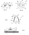
- FIG. 3 shows schematically an example of ET stirrup allowing to move step by step on a guide tube by virtue of three piezoelectric actuators AA, AB and AC operating in two possible sequences: forward or reverse.
- the AA and AB actuators are electric clamps that lock one or the other legs of the stirrup on the guide tube.
- the body of the stirrup can be extended by the AC actuator, thus sliding the free leg on the tube.
- the latter can be replaced by a flexible blade and the stirrup can be linked to one of the frames constituting the tube of the telescope, this time.
- the support device D comprises six flexible blades deployable Oij, cooperating in pairs.
- the index i is between 1 and 3 and allows to designate a pair of blades
- any fastening means may be considered to secure the first EX1 and second EX2 ends of each blade Oij (here) to the first C1 and second C2 frames.
- the six flexible blades are slightly offset towards the outside of the tube thanks to the Pkn fastening lugs in order not to intercept the useful optical flux (delimited here by the inside diameter of the frames C1 and C2).
- the first C1 and second C2 frames have substantially identical diameters. But this is not obligatory.
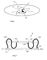
- the second mirror M2 which is smaller than the first mirror M1, is then preferably attached to the second frame C2 by means of three rigid blades placed tangentially at 120 ° from each other, for example. Such a method of attachment is partially and schematically illustrated in FIG.
- a housing B containing a mirror fixing device (DFM), not shown, on which the second mirror M2 is bonded.
- the mirror fixing device (intermediate between the housing B and the second mirror M2) has the role of filtering the stresses due to the fixing screws (clamping) which could deform the second mirror M2.
- the housing B is fixed to the second frame C2 by means of a device, generally called spider, and consists of three rigid blades L1 to L3 tangential to the lateral surface of said housing B.
- the expansion of the blades results in a rotation of the housing B which does not disturb the instrument of observation and does not entail constraints on the second mirror M2.
- first EX1 and second EX2 ends can for example be done by means of a mechanical connection to block any degree of freedom of movement.
- An example of mechanical connection is illustrated in FIG. 9.
- each end EX1 or EX2 of a blade Oij (for example 022) is embedded between two immobilizing parts PF1 and PF2.
- the piece PF2 is for example integral (or integral) with a Pkn bracket of one of the first C1 and second C2 frames and has two threaded holes TF.
- the index k is between 1 and 3 and makes it possible to designate one of the three fixing lugs of the first C1 or the second C2 frame
- the index n is between 1 and 2 and makes it possible to designate the first C1 or the second C2 frame. Consequently, the fixing lugs P11, P12 and P13 belong to the first frame C1, while the fixing lugs P21, P22 and P23 belong to the second frame C2.
- the part PF1 has a portion whose shape (here convex) is complementary to that (here concave) of a portion of the part PF1 and comprises two through-holes TT to allow the passage of bolts B.
- the part PF2 is reported or integral (or integral) of a Pkn bracket of one of the first C1 and second C2 frames.
- Each end EX1 or EX2 also includes two through holes to allow the passage of bolts B and thus its immobilization relative to parts PF1 and PF2.
- each end EX1, EX2 may be drowned (or potted) in an immobilizing material, such as a polymerizable resin, in order to block any degree of freedom of movement.
- an immobilizing material such as a polymerizable resin
- each flexible blade Oij (only 032 and 031 are shown) supports here four curvatures in at least one chosen plane when placed in its folded initial position.
- the number of bends that a flexible blade must bear depends also on the space available for folding and / or the length that it must have when unfolded, that is to say placed in its final position illustrated on Figure 8.
- the folds (or curvatures) of a flexible blade Oij can all be located substantially in the same plane, or in at least two different planes (because of its flexibility). Furthermore, the folds (or curvatures) of the various flexible blades Oij are not necessarily identical to each other.
- the average plane of each flexible blade can be oriented optimally to allow folding of the flexible blades in six planes perpendicular to the plane of the first frame C1 and to facilitate guidance during deployment.
- Each of these six planes is specific to a blade and defined by the three points EX1, EX2 in the folded blade position and EX2 in the unfolded blade position.
- the average plane of the flexible blade must then be perpendicular to this plane. Indeed, in this case, the folded blades are not biased laterally which improves their stability in the folded position.
- Figure 5 is schematically illustrated the optimal orientation of the flexible blades in a top view of the telescope tube.
- the inner diameter of the C1 frame has been reduced slightly here for ease of understanding.
- the trace of the first end EX1 of the flexible blade 011 on the bracket P11 here forms an angle ⁇ of about 30 ° with the nearest axis of symmetry. It is the same for all the ends of flexible blades.
- the secondary mirror M2 (second element) and / or means responsible for guiding the secondary mirror M2 and / or retractable means loaded with immobilize the second C2 and third C3 frames, as well as possibly the blades Oij. It is also possible to provide means for moving at least one of the first EX1 and / or second EX2 ends of the blades Oij.
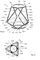
- the support device D comprises at least three pairs of flexible blades Oij in each of which the two blades (Oi1 and Oi2) constitute two non-parallel sides of a polyhedron having three sides (triangle) or four sides (trapezium), once they are placed in their respective final positions.
- These three pairs of flexible blades Oij define a hexapod once they are placed in their respective end positions (see Figure 4). This hexapod is folded substantially along the main axis of symmetry XX when the three pairs of flexible blades Oij are placed in their respective initial positions.
- two flexible blades Oi1 and Oi2 of each of the three pairs constitute two non-parallel sides of a trapezium Ti (T1 to T3), represented by dotted lines in the case of T3, once they are placed in their respective final positions.
- the two flexible blades Oij of a pair create forces whose vector components contribute to establishing a balance in the plane of the figure.
- the balance of the assembly is then ensured by the cooperation of the three pairs of blades whose second ends E2 are judiciously distributed at the periphery of the second frame C2. More specifically, the second ends E2 are here secured to the Pkn fastening tabs which are placed substantially at 120 ° from each other.
- each flexible deployable blade Oij is subdivided into first Oij1 and second Oij2 sub-blades.
- Each first sub-blade Oij1 comprises the first end EX1 and a third end EX3 and each second sub-blade Oij2 comprises the second end EX2 and a fourth end EX4.
- each second sub-blade Oij2 is flexible, while each first sub-blade Oij1 can be either flexible or rigid.
- Each third end EX3 of a first sub-blade Oij1 is secured indirectly to the fourth end EX4 of the second sub-blade with which it forms a blade Oij, via a third rigid frame C3 interposed between the first C1 and second C2 frames. More specifically, the third end EX3 of each first sub-blade Oij1 is secured to a first face of the third frame C3, while the fourth end EX4 of each second sub-blade Oij2 is secured to a second face of the third frame C3, by example opposite to the first face, and substantially at the same level as the corresponding third end EX3.
- any fastening means may be envisaged for joining the third EX3 and fourth EX4 ends of the sub-blades Oij1 and Oij2 to the third frame C3.
- the fastening can for example be done by means of a mechanical connection intended to block any degree of freedom of movement, and for example by embedding as illustrated in FIG. 9.
- a mechanical connection intended to block any degree of freedom of movement
- an immobilizing material such as a polymerizable resin
- the third frame C3 is arranged in the form of an equilateral triangle. Although this does not appear in Figure 10, the frame is hollowed in the center. But other forms of framework can be envisaged.
- the first sub-blades Oij1 cooperate in pairs, just like the second sub-blades Oij2.
- Each sub-blade Oij1, Oij2 is of the same type as those presented above in the first and second exemplary embodiments.
- the folding mode of the first sub-blades Oij1 in their initial position folded by curvatures, like that of the second sub-blades Oij2, is therefore identical to that described above, each sub-blade having to support at least two curvatures in at least one plan.
- the support device D comprises three pairs of first sub-blades (flexible or rigid) Oij1 in each of which the two sub-blades (Oi11 and Oi21) constitute two non-parallel sides of a polyhedron having three sides (triangle) or four sides (trapezium), once they are placed in their respective end positions.
- these three pairs of first sub-blades Oij1 ((0111, 0121), (0211, 0221), (0311, O321)) define a first hexapode once they are placed in their respective end positions. . Otherwise they constitute a first hexapode from the beginning.
- This first hexapod is, in case of flexibility, folded substantially along the main axis of symmetry XX when the three pairs of first flexible sub-blades Oij1 are placed in their respective initial positions.
- the support device D also comprises three pairs of second flexible sub-blades Oij2 in each of which the two sub-blades (Oi12 and Oi22) constitute two non-parallel sides of a polyhedron having three sides (triangle) or four sides (trapeze), once they are placed in their respective end positions.
- These three pairs of flexible second sub-blades Oij2 ((O112, 0122), (0212, 0222), (0312, 0322)) define a second hexapode once they are placed in their respective end positions.
- This second hexapode is also folded substantially along the main axis of symmetry XX when the three pairs of second flexible sub-blades Oij2 are placed in their respective initial positions.
- the support structure is thus somehow made up of two hexapods mounted head to tail.
- two first sub-blades Oi11 and Oi21 of each of the three pairs of the first hexapode constitute two non-parallel sides of a trapezium Ti1 (T11 to T31), represented by dotted lines in the case of T31, once they are placed in their respective end positions.
- two second flexible sub-blades Oi12 and Oi22 of each of the three pairs of the second hexapode constitute two non-parallel sides of another trapezium Ti2 (T12 to T32), represented by dotted lines in the case of T12, once they are placed in their respective final positions.
- pairs of first sub-blades Oi11 and Oi21 may constitute parallel sides of polyhedra (triangles or trapezoids) having first dimensions
- the pairs of second sub-blades Oi12 and Oi22 may constitute parallel sides of polyhedra (triangles or trapezes) having second dimensions, possibly different from the first dimensions (as is the case in the illustrated example).
- pairs of first sub-blades Oi11 and Oi21 are parallel sides of polyhedra of a first type (for example triangles)
- pairs of second sub-blades Oi12 and Oi22 are parallel sides of polyhedra of a second type (eg trapezoids).
- the folding mode of the first sub-blades Oij1 in their initial position may therefore be different from that of the second sub-blades Oij2 in their initial position.
- the number of curvatures supported by the first sub-blades Oij1 may be different from that supported by the second sub-blades Oij2.
- the same is true of the number of planes in which the folds (or curvatures) are made.
- the trapeziums and / or triangles formed are preferably of the isosceles type.
- the configuration illustrated in Figures 10 and 11 is advantageous in terms of stability. It can be made optimal when the third frame C3 is in a circle which has a diameter twice that of the first C1 and second C2 frames.
- the trace of the EX4 end of the blade 0212 on the third frame C3 forms an angle ⁇ of about 60 ° with the nearest axis of symmetry.
- the trace of the EX2 end of the blade 0212 is substantially parallel to the nearest axis of symmetry.
- each of the three triangles can fold in the same plane as the two flexible blades that constitute it. In this case, the folded blades are not (or almost not) biased laterally (out of the plane of each triangle) which improves the stability of the folded position.
- first and second examples it is preferable to provide means responsible for damping the displacement of the secondary mirror M2 (second element) and / or means responsible for guiding the secondary mirror M2 and / or retractable means responsible for immobilizing the second C2 and third C3 frames, as well as possibly the first Oij1 and second Oij2 sub-blades. It is also possible to provide means for moving at least one of the first EX1 and / or second EX2 and / or third EX3 and / or fourth EX4 ends of the sub-blades Oij1 and Oij2.
Abstract
Description
L'invention concerne les équipements embarqués sur des satellites, et plus particulièrement les dispositifs supportant certains éléments de ces équipements.The invention relates to equipment embedded on satellites, and more particularly the devices supporting certain elements of this equipment.
On entend ici par « équipement embarqué », tout équipement solidarisé au moins partiellement à au moins un satellite. Il peut notamment s'agir d'un instrument d'observation, destiné à remplir une mission d'observation spatiale et par exemple constitué d'un ou plusieurs télescopes spatiaux, éventuellement répartis sur plusieurs satellites, ou d'au moins une antenne radar, ou bien d'une tuyère plasmique, ou encore d'un capteur.The term "on-board equipment" here means any equipment that is at least partially secured to at least one satellite. It can in particular be an observation instrument, intended to fulfill a space observation mission and for example consisting of one or more space telescopes, possibly distributed over several satellites, or at least one radar antenna, or a plasma nozzle, or a sensor.
Par ailleurs, on entend ici par « mission d'observation spatiale » aussi bien les missions destinées à observer la Terre depuis l'espace que les missions destinées à observer une partie de l'univers depuis l'espace.Moreover, here we mean by "space observation mission" both the missions intended to observe the Earth from space and the missions intended to observe a part of the universe from space.
Afin de remplir des missions d'observation, certains satellites comportent au moins une partie d'un instrument d'observation, comme par exemple un télescope spatial, par exemple de type Cassegrain, Grégory, Korsch, Ritchey-Chrétien, ou Newton.In order to fulfill observation missions, certain satellites comprise at least part of an observation instrument, for example a space telescope, for example of the Cassegrain, Grégory, Korsch, Ritchey-Chrétien or Newton type.
De tels télescopes comportent au moins un dispositif de support destiné à maintenir un premier élément, tel qu'un miroir (éventuellement de type primaire (et fréquemment appelé collecteur de flux)), éloigné d'une distance choisie d'un second élément, tel qu'un miroir (éventuellement de type secondaire) ou une partie d'un détecteur, implantée au niveau du plan focal où se forment les images. Un tel dispositif constitue avec les éléments qu'il supporte une structure à configuration géométrique fixe. Cette dernière est dimensionnée de manière à supporter les contraintes mécaniques dues à la pesanteur et aux charges (ou forces) subies pendant les différentes phases du lancement, et notamment lors du décollage de la fusée dans laquelle est embarqué le satellite que le dispositif équipe.Such telescopes comprise at least one support device intended to maintain a first element, such as a mirror (possibly of primary type (and frequently called flux collector)), remote from a selected distance from a second element, such as a mirror (possibly of secondary type) or a part of a detector, implanted at the focal plane where the images are formed. Such a device constitutes with the elements that it supports a fixed geometric configuration structure. The latter is dimensioned to withstand the mechanical stresses due to gravity and loads (or forces) incurred during the various phases of the launch, and especially during takeoff of the rocket in which is embedded the satellite that the device team.
Une fois la mission commencée, les charges supportées par la structure sont très faibles, voire quasiment nulles. La structure s'avère donc surdimensionnée pendant toute sa durée de vie opérationnelle, ce qui induit une inertie, notamment transverse, plus importante que celle qui est réellement nécessaire. Cette « sur-inertie » ne pouvant pas être réduite en orbite, elle limite la vitesse de dépointage du télescope et donc le temps pendant lequel il peut acquérir des images, ce qui est pénalisant notamment lorsqu'il est embarqué sur un satellite dit « agile » et/ou lorsqu'un « mosaïquage » doit être effectué (du fait que le champ de l'instrument est inférieur au champ à observer).Once the mission has begun, the charges borne by the structure are very weak or almost nil. The structure is therefore oversized throughout its operational life, which induces an inertia, especially transverse, greater than that which is really necessary. This "over-inertia" can not be reduced to orbit, it limits the speed of misalignment of the telescope and therefore the time during which it can acquire images, which is penalizing especially when it is embedded on a satellite called "agile" And / or when "mosaicing" must be done (because the field of the instrument is smaller than the field to be observed).
En outre, le surdimensionnement de la structure de support se traduit par une masse et un encombrement additionnels qui imposent l'utilisation de fusées de plus grande capacité d'emport et/ou peuvent limiter le nombre de satellites pouvant être lancés par une même fusée.In addition, the over-dimensioning of the support structure results in additional weight and bulk that require the use of rockets of greater carrying capacity and / or may limit the number of satellites that can be launched by the same rocket.
L'invention a donc pour but d'améliorer la situation.The invention therefore aims to improve the situation.
Elle propose à cet effet un dispositif de support de premier et second éléments d'un équipement spatial (comme par exemple un instrument d'observation), destiné à être embarqué sur au moins un satellite, comprenant au moins deux lames flexibles pouvant être déployées (ou plus simplement « déployables ») comprenant chacune une première et une deuxième extrémités respectivement solidarisées aux premier et second éléments et agencées chacune de manière à prendre au moins des positions initiale (repliée par courbures) et finale (dépliée) dans lesquelles elles maintiennent le premier élément éloigné du second élément respectivement d'une première et d'une seconde distances choisies, la seconde distance étant supérieure à la première.It proposes for this purpose a device for supporting first and second elements of a space device (such as an observation instrument), intended to be on board at least one satellite, comprising at least two flexible blades that can be deployed ( or more simply "deployable") each comprising a first and a second end respectively secured to the first and second elements and each arranged to take at least initial positions (folded by curvature) and final (unfolded) in which they maintain the first element distant from the second element respectively of a first and a second selected distances, the second distance being greater than the first.
Le dispositif de support selon l'invention peut comporter d'autres caractéristiques qui peuvent être prises séparément ou en combinaison, et notamment :
- au moins trois lames flexibles comprenant chacun des première et deuxième extrémités respectivement solidarisées aux premier et second éléments en des positions différentes choisies et agencés de manière à prendre des positions initiales et finales respectives dans lesquelles elles maintiennent le premier élément éloigné du second élément respectivement des première et seconde distances choisies ;
- trois paires de lames dans chacune desquelles les deux lames peuvent constituer deux côtés non parallèles d'un trapèze une fois qu'elles sont placées dans leurs positions finales respectives. ;

- les lames de chaque paire peuvent être de longueurs identiques afin que le trapèze correspondant soit de type isocèle ;
- en variante, trois paires de lames dans chacune desquelles les deux lames peuvent constituer deux côtés d'un triangle une fois qu'elles sont placées dans leurs positions finales respectives ;

- les lames de chaque paire peuvent être de longueurs identiques afin que le triangle correspondant soit de type isocèle ;
-
- un premier cadre sur lequel peuvent être fixés le premier élément et la première extrémité de chaque lame, afin d'être solidarisée au premier élément, et un deuxième cadre sur lequel peuvent être fixés le second élément et la deuxième extrémité de chaque lame, afin d'être solidarisée au second élément ;
- les première et deuxième extrémités de chaque lame peuvent être respectivement fixées aux premier et deuxième cadres par une liaison mécanique et/ou un matériau d'immobilisation destiné(e)(s) à bloquer tout degré de liberté de mouvement ;

- chaque lame peut comprendre une première sous-lame comportant la première extrémité et une troisième extrémité et une seconde sous-lame comportant la deuxième extrémité et une quatrième extrémité. Dans ce cas, on peut prévoir un troisième cadre intercalé entre les premier et deuxième cadres et sur lequel sont fixés la troisième extrémité de chaque première sous-lame et la quatrième extrémité de chaque seconde sous-lame ;

- les troisième et quatrième extrémités de chaque première sous-lame et chaque seconde sous-lame peuvent être fixées au troisième cadre par une liaison mécanique et/ou un matériau d'immobilisation destiné(e)(s) à bloquer tout degré de liberté de mouvement ;
-
- des moyens d'amortissement peuvent être chargés d'amortir le déplacement du second élément lorsque chaque lame rejoint sa position finale ;
- des moyens de guidage peuvent être chargés de guider une partie au moins du déplacement du second élément lorsque chaque lame évolue de sa position initiale (repliée ou lovée ou enroulée) vers sa position finale (dépliée ou délovée ou déroulée), ou en d'autres termes de borner la cinématique du mouvement de déploiement ;
- des moyens de déplacement peuvent être chargés de déplacer la première extrémité et/ou la deuxième extrémité de l'une au moins des lames afin de contrôler sa position finale et le positionnement du premier élément par rapport au second élément ;
- des moyens d'immobilisation escamotables peuvent être chargés d'immobiliser le premier élément et/ou le second élément par rapport à une structure rigide de l'équipement tant que chaque lame est placée dans sa position initiale ;
- chaque lame flexible peut être agencée de manière à supporter au moins deux courbures dans au moins un plan choisi lorsqu'elle est placée dans la position initiale ;
- chaque lame flexible est par exemple capable de supporter au moins deux courbures dans un même plan lorsqu'elle est placée dans sa position initiale ;

- en variante chaque lame flexible est par exemple capable de supporter au moins deux courbures dans au moins deux plans différents lorsqu'elle est placée dans sa position initiale ;

- chaque lame flexible peut être réalisée en fibres de carbone ;

-
- le premier élément est par exemple un miroir, éventuellement de type primaire ;
- le second élément est par exemple un miroir secondaire ou une partie d'un détecteur, installée dans un plan focal.
- at least three flexible blades each comprising first and second ends respectively secured to the first and second elements in different positions chosen and arranged to take respective initial and final positions in which they maintain the first element away from the second element respectively first and second distances selected;
- three pairs of blades in each of which the two blades can form two non-parallel sides of a trapezium once they are placed in their respective end positions. ;
- the blades of each pair may be of identical lengths so that the corresponding trapezium is of the isosceles type;
- alternatively, three pairs of blades in each of which the two blades can constitute two sides of a triangle once they are placed in their respective end positions;
- the blades of each pair may be of identical lengths so that the corresponding triangle is of the isosceles type;
-
- a first frame on which can be fixed the first element and the first end of each blade, in order to be secured to the first element, and a second frame on which can be fixed the second element and the second end of each blade, in order to to be secured to the second element;
- the first and second ends of each blade can be respectively fixed to the first and second frames by a mechanical connection and / or an immobilization material for (e) (s) to block any degree of freedom of movement;
- each blade may comprise a first sub-blade having the first end and a third end and a second sub-blade having the second end and a fourth end. In this case, it is possible to provide a third frame interposed between the first and second frames and on which are fixed the third end of each first sub-blade and the fourth end of each second sub-blade;
- the third and fourth ends of each first sub-blade and each second sub-blade can be attached to the third frame by a mechanical connection and / or an immobilizing material for blocking any degree of freedom of movement ;
-
- damping means may be responsible for amortizing the moving the second element when each blade reaches its final position;
- guide means may be instructed to guide at least a part of the displacement of the second element when each blade moves from its initial position (folded or coiled or wound) to its final position (unfolded or curved or unwound), or in other terms to limit the kinematics of the movement of deployment;
- displacement means may be responsible for moving the first end and / or the second end of at least one of the blades to control its final position and the positioning of the first element relative to the second element;
- retractable immobilizing means may be responsible for immobilizing the first element and / or the second element relative to a rigid structure of the equipment as long as each blade is placed in its initial position;
- each flexible blade can be arranged to support at least two curvatures in at least one selected plane when it is placed in the initial position;
- each flexible blade is for example capable of supporting at least two curvatures in the same plane when it is placed in its initial position;
- alternatively each flexible blade is for example capable of supporting at least two curvatures in at least two different planes when placed in its initial position;
- each flexible blade can be made of carbon fibers;
-
- the first element is for example a mirror, possibly of primary type;
- the second element is for example a secondary mirror or a part of a detector, installed in a focal plane.
L'invention propose également un équipement spatial, de type instrument d'observation, comportant au moins un ensemble de premier et second éléments supporté par au moins un dispositif de support du type de celui présenté ci-avant.The invention also proposes a space device, of the observation instrument type, comprising at least one set of first and second elements supported by at least one support device of the type of the one presented above.
D'autres caractéristiques et avantages de l'invention apparaîtront à l'examen de la description détaillée ci-après, et des dessins annexés, sur lesquels :
- les figures 1A et 1B illustrent de façon très schématique, respectivement dans des vues en coupe transversale (et diamétrale) et du dessus, un premier exemple de réalisation d'un dispositif de support d'éléments de télescope, selon l'invention, placé dans sa position initiale (lames repliées par courbures),
- la figure 2 illustre de façon très schématique, dans une vue de côté, le premier exemple de réalisation du dispositif de support des figures 1A et 1 B, lorsqu'il est placé dans sa position finale (dépliée),
- la figure 3 illustre de façon très schématique, dans une vue de côté, un exemple de réalisation de moyen de déplacement de type « réptateur » (ou « inchworm »),
- la figure 4 illustre de façon très schématique, dans une vue en perspective, un deuxième exemple de réalisation d'un dispositif de support d'éléments de télescope, selon l'invention, placé dans sa position finale (dépliée),
- la figure 5 illustre de façon très schématique, dans une vue du dessus légèrement déformée, le deuxième exemple de réalisation du dispositif de support de la figure 4, lorsqu'il est placé dans sa position finale (dépliée),
- la figure 6 illustre de façon très schématique et partielle, dans une vue en perspective, un exemple de mode de fixation d'un second miroir sur un deuxième cadre,
- la figure 7 illustre de façon très schématique, dans une vue de côté, le deuxième exemple de réalisation du dispositif de support de la figure 4, lorsqu'il est placé dans sa position initiale (lames repliées par courbures),
- la figure 8 illustre de façon très schématique, dans une vue de côté, le deuxième exemple de réalisation du dispositif de support de la figure 4, lorsqu'il est placé dans sa position finale (dépliée),
- la figure 9 illustre de façon très schématique, dans une vue en perspective, un exemple de mode de fixation des lames flexibles déployables d'un dispositif de support selon l'invention,
- la figure 10 illustre de façon schématique, dans une vue en perspective, un troisième exemple de réalisation d'un dispositif de support d'éléments de télescope, selon l'invention, placé dans sa position finale (dépliée), et
- la figure 11 illustre de façon très schématique, dans une vue du dessus, le troisième exemple de réalisation du dispositif de support de la figure 10, lorsqu'il est placé dans sa position finale (dépliée).
- FIGS. 1A and 1B very schematically illustrate, respectively in cross-sectional (and diametrical) and top views, a first embodiment of a telescope element support device, according to the invention, placed in its initial position (curved blades),
- FIG. 2 very schematically illustrates, in a side view, the first exemplary embodiment of the support device of FIGS. 1A and 1B, when it is placed in its final (unfolded) position,
- FIG. 3 very schematically illustrates, in a side view, an exemplary embodiment of "rewinder" type of displacement means (or "inchworm"),
- FIG. 4 very schematically illustrates, in a perspective view, a second exemplary embodiment of a device for supporting telescope elements, according to the invention, placed in its final (unfolded) position,
- FIG. 5 very schematically illustrates, in a slightly deformed top view, the second embodiment of the support device of FIG. 4, when it is placed in its final (unfolded) position,
- FIG. 6 very schematically and partially illustrates, in a perspective view, an exemplary method of fixing a second mirror on a second frame,
- FIG. 7 very schematically illustrates, in a side view, the second exemplary embodiment of the support device of FIG. 4, when it is placed in its initial position (blades bent by curvatures),
- FIG. 8 very schematically illustrates, in a side view, the second exemplary embodiment of the support device of FIG. 4, when it is placed in its final (unfolded) position,
- FIG. 9 very schematically illustrates, in a perspective view, an example of a method of attachment of the deployable flexible blades of a support device according to the invention,
- FIG. 10 schematically illustrates, in a perspective view, a third exemplary embodiment of a telescope element support device, according to the invention, placed in its final (unfolded) position, and
- Figure 11 schematically illustrates, in a view from above, the third embodiment of the support device of Figure 10, when placed in its final position (unfolded).
Les dessins annexés pourront non seulement servir à compléter l'invention, mais aussi contribuer à sa définition, le cas échéant.The attached drawings may not only serve to complete the invention, but also contribute to its definition, if any.
L'invention a pour objet de permettre la réduction de la masse et de l'inertie, notamment transverse, d'un équipement spatial embarqué sur au moins un satellite destiné à être installé en orbite au moyen d'une fusée (ou d'un lanceur).The object of the invention is to allow the reduction of the mass and the inertia, in particular transverse, of space equipment on board at least one satellite intended to be installed in orbit by means of a rocket (or a launcher).
A cet effet, l'invention propose un dispositif de support (D) destiné à supporter au moins deux éléments, d'un équipement spatial, embarqués sur un même satellite.For this purpose, the invention proposes a support device (D) intended to support at least two elements, a space equipment, embedded on the same satellite.
On considère dans ce qui suit que l'équipement spatial est un instrument d'observation tel qu'un télescope embarqué sur un satellite d'observation, par exemple de type agile.Space equipment is considered in the following as an observation instrument such as a telescope on an observation satellite, for example of agile type.
Mais, l'invention n'est pas limitée à ce type d'équipement spatial. En effet, il pourrait s'agir d'un instrument d'observation constitué de plusieurs télescopes répartis sur plusieurs satellites volant en formation, ou bien d'une antenne radar comportant un premier élément tel qu'un réflecteur et un second élément tel qu'une source. Il pourrait également s'agir de tuyères dites plasmiques destinées à contrôler l'attitude du satellite et devant être déployées une fois le satellite en orbite, de manière à augmenter le bras de levier pour réduire les forces à appliquer. Il pourrait également s'agir de capteurs dont une partie, destinée à l'acquisition de données, doit être écartée du satellite une fois celui-ci placé sur son orbite, de manière à ne pas faire l'objet d'une perturbation électromagnétique ou simplement électrique.But, the invention is not limited to this type of space equipment. Indeed, it could be an observation instrument consisting of several telescopes distributed over several satellites flying in formation, or a radar antenna comprising a first element such as a reflector and a second element such as a source. They could also be so-called plasma thrusters intended to control the attitude of the satellite and to be deployed once the satellite in orbit, so as to increase the lever arm to reduce the forces to be applied. It could also be sensors, part of which, for the acquisition of data, must be removed from the satellite once it is placed in its orbit, so as not to be subjected to an electromagnetic disturbance or simply electric.
Le dispositif de support (D) selon l'invention fait partie de l'équipement, ici un télescope, dont il supporte au moins deux des éléments et est généralement solidarisé à la structure du satellite. Lorsque l'instrument d'observation est constitué de plusieurs télescopes embarqués sur plusieurs satellites, il comporte plusieurs ensembles de premier et second éléments, chacun supporté par un dispositif de support D installé sur l'un des satellites.The support device (D) according to the invention is part of the equipment, here a telescope, which it supports at least two of the elements and is generally secured to the structure of the satellite. When the instrument observation system consists of several telescopes embedded on several satellites, it comprises several sets of first and second elements, each supported by a support device D installed on one of the satellites.
Dans ce qui suit, on considère à titre d'exemple non limitatif que le télescope est de type Cassegrain et que les deux éléments supportés par le dispositif de support (D) selon l'invention sont un miroir dit « primaire » et un miroir dit « secondaire ».In the following, we consider as a non-limiting example that the telescope is Cassegrain type and that the two elements supported by the support device (D) according to the invention are a mirror called "primary" and a so-called mirror "Secondary".
Mais l'invention n'est pas limitée à ce type de télescope spatial. Elle concerne en effet tous les télescopes (ou instruments d'observation) dans lesquels deux éléments participant à l'observation (ou acquisition de données) doivent être éloignés l'un de l'autre d'une distance choisie. Ces deux éléments peuvent par conséquent être deux miroirs (l'un étant de type primaire et l'autre de type secondaire), comme par exemple dans le cas des télescopes de type Grégory, Korsch ou Ritchey-Chrétien, ou un miroir et une partie d'un détecteur, implantée au niveau du plan focal où se forment les images, comme par exemple dans le cas d'un télescope de type Newton, ou encore un miroir plan de renvoi et un autre miroir.But the invention is not limited to this type of space telescope. It concerns indeed all telescopes (or observation instruments) in which two elements participating in the observation (or data acquisition) must be distant from each other by a chosen distance. These two elements can therefore be two mirrors (one being of the primary type and the other of the secondary type), as for example in the case of the Grégory, Korsch or Ritchey-Chrétien telescopes, or a mirror and a part a detector, located at the focal plane where the images are formed, as for example in the case of a Newton-type telescope, or a reflecting plane mirror and another mirror.
On se réfère tout d'abord aux figures 1 et 2 pour décrire un premier exemple de réalisation d'un dispositif de support D selon l'invention.Referring first to Figures 1 and 2 to describe a first embodiment of a support device D according to the invention.
Le dispositif de support D comprend au moins deux lames flexibles déployables 01 et 02 comportant chacune des première EX1 et deuxième EX2 extrémités respectivement solidarisées au miroir primaire M1 et au miroir secondaire M2 du télescope (ou à la partie d'un détecteur située dans le plan focal).The support device D comprises at least two deployable
Dans l'exemple illustré sur les figures 1 et 2, le dispositif de support D ne comprend que deux lames flexibles déployables 01 et 02. Mais, comme on le verra plus loin il peut en comporter plusieurs, par exemple trois ou quatre, voire même plus.In the example illustrated in FIGS. 1 and 2, the support device D comprises only two flexible
Il est important de noter que la solidarisation des extrémités EX1 et EX2 de chaque lame 01, 02 aux miroirs primaire M1 et secondaire M2 peut être directe ou indirecte. Dans l'exemple illustré sur les figures 1 et 2, cette solidarisation est indirecte. Plus précisément, le dispositif de support D comprend, d'une part, un premier cadre rigide C1 sur lequel est fixé le miroir primaire M1 et la première extrémité EX1 de chaque lame flexible 01, 02, et d'autre part, un deuxième cadre rigide C2 sur lequel est fixé le miroir secondaire M2 et la deuxième extrémité EX2 de chaque lame flexible 01, 02.It is important to note that the joining of the ends EX1 and EX2 of each
Dans l'exemple de réalisation, illustré schématiquement sur les figures 1 et 2, le deuxième cadre C2 présente un diamètre plus petit que celui du premier cadre C1. Mais, comme on le verra plus loin en référence aux figures 4 à 9, les premier C1 et second C2 cadres peuvent présenter des diamètres sensiblement identiques.In the exemplary embodiment, diagrammatically illustrated in FIGS. 1 and 2, the second frame C2 has a diameter smaller than that of the first frame C1. But, as will be seen below with reference to Figures 4 to 9, the first C1 and second C2 frames may have substantially identical diameters.
Tout moyen de fixation peut être envisagé pour solidariser les première EX1 et deuxième EX2 extrémités de chaque lame 01, 02 (ici) aux premier C1 et deuxième C2 cadres. Cela peut par exemple se faire au moyen d'une liaison mécanique destinée à bloquer tout degré de liberté de mouvement. En variante ou en complément, on peut noyer (ou « empoter ») chaque extrémité EX1, EX2 dans un matériau d'immobilisation, comme par exemple une résine polymérisable, afin de bloquer tout degré de liberté de mouvement.Any fastening means may be envisaged to secure the first EX1 and second EX2 ends of each
Les lames 01, 02 sont agencées de manière à prendre au moins des positions initiales repliées par courbures dans lesquelles elles maintiennent le miroir primaire M1 éloigné du miroir secondaire M2 d'une première distance choisie, et des positions finales dépliées dans lesquelles elles maintiennent le miroir primaire M1 éloigné du miroir secondaire M2 d'une seconde distance choisie, supérieure à la première.The
Il est important de noter que les repliements (ou les courbures) d'une lame flexible 01, 02 peuvent tous être situés sensiblement dans un même plan, ou bien dans au moins deux plans différents (en raison de sa flexibilité). Par ailleurs, les repliements (ou les courbures) des différentes lames flexibles 01 et 02 ne sont pas nécessairement identiques entre eux.It is important to note that the folds (or curvatures) of a
On peut par exemple utiliser des lames flexibles incurvées, du type de celle qui est partiellement illustrée sur la figure 6. Chaque lame flexible 01, 02 pourrait être agencée sous la forme d'un mètre à ruban métallique. Cependant, afin de présenter la stabilité thermique requise, chaque lame 01, 02 est préférentiellement réalisée en fibres de carbone.For example, curved flexible blades of the type partially illustrated in FIG. 6 may be used. Each
Chaque lame flexible peut également être constituée de deux lames de type mètre ruban, rattachées par leurs bords longitudinaux et positionnées de sorte que les cavités définies par leurs bombements soient face à face une fois placées dans la position finale. Lorsqu'elles sont en position repliées, les deux lames sont plaquées l'une contre l'autre et sont dépourvues de bombement.Each flexible blade can also be made of two blades ribbon type, attached by their longitudinal edges and positioned so that the cavities defined by their bulges are face to face once placed in the final position. When in the folded position, the two blades are pressed against each other and are free of bulging.
Comme cela est schématiquement illustré sur la figure 1A, chaque lame flexible 01, 02 supporte au moins deux courbures dans au moins un plan choisi lorsqu'elle est placée dans sa position initiale. Le nombre de courbures que doit supporter une lame flexible dépend en fait de la place disponible pour le repliement et/ou de la longueur qu'elle doit présenter lorsqu'elle est dépliée, c'est-à-dire placée dans sa position finale illustrée sur la figure 2 et/ou de sa limite élastique qui est associée à un rayon de courbure minimal en dessous duquel elle peut être définitivement déformée (délaminée).As schematically illustrated in FIG. 1A, each
Comme cela est illustré sur la figure 1A, lorsque les lames 01 et 02 sont placées dans leur position initiale repliée les miroirs primaire M1 et secondaire M2 sont rapprochés, de manière à rendre compact (ou à réduire son extension longitudinale initiale de) ce que l'homme de l'art appelle habituellement le « tube » du télescope, suivant son axe de révolution XX, tant que le satellite sur lequel il est embarqué n'a pas rejoint son orbite de mission.As shown in FIG. 1A, when the
Grâce à cette compacité (ou ce faible encombrement) et à la structure allégée qu'offre le dispositif de support D, on peut utiliser une fusée de plus petite capacité d'emport et/ou augmenter le nombre de satellites qu'une fusée peut placer en orbite (ou lancer).Thanks to this compactness (or small footprint) and the lightened structure offered by the support device D, it is possible to use a rocket of smaller carrying capacity and / or to increase the number of satellites that a rocket can place. in orbit (or throw).
La structure de support étant allégée, il est préférable de prévoir des moyens d'immobilisation destinés à immobiliser, pendant la phase de lancement, le miroir secondaire (second élément) M2 (ou plus précisément le deuxième cadre C2 auquel il est fixé), ainsi qu'éventuellement chaque lame flexible déployable 01, 02, par rapport à la structure principale du télescope (à laquelle est fixé le miroir primaire (premier élément) M1 (ou plus précisément le premier cadre C1 auquel il est fixé)). Tout moyen d'immobilisation escamotable connu de l'homme de l'art peut être utilisé à cet effet.The support structure being lightened, it is preferable to provide immobilization means for immobilizing, during the launch phase, the secondary mirror (second element) M2 (or more precisely the second frame C2 to which it is attached), and possibly each flexible
Comme cela est illustré sur la figure 2, lorsque les lames 01 et 02 sont placées dans leur position finale dépliée les miroirs primaire M1 et secondaire M2 sont éloignés de la seconde distance choisie, qui est celle dans laquelle le télescope fonctionne de façon optimale. L'encombrement du tube du télescope est donc notablement plus important que lorsque les lames 01 et 02 sont dans leur position initiale repliée. Cependant, la structure de support étant allégée, l'inertie du télescope est réduite, si bien que la vitesse à laquelle il peut être dépointé est accrue, permettant ainsi d'augmenter le temps pendant lequel il peut acquérir des images.As illustrated in FIG. 2, when the
Les première EX1 et deuxième EX2 extrémités de chaque lame 01 et 02 étant fixées sur des parties des premier C1 et deuxième C2 cadres qui sont situées à la périphérie des miroirs primaire M1 et secondaire M2, aucune lame 01, 02 ne se trouve sur le trajet des photons collectés par le télescope. En d'autres termes, la ou les lames flexibles déployables respecte(nt) le champ de vue du télescope.The first EX1 and second EX2 ends of each
Les lames flexibles Oij sont préférentiellement maintenues pendant la phase de lancement dans leur position initiale (sous contrainte élastique) grâce à des moyens d'immobilisation escamotables (non représentés). Il est également préférable de prévoir des moyens d'immobilisation escamotables destinés à immobiliser pendant la phase de lancement le miroir secondaire (second élément) M2 (ou plus précisément le deuxième cadre C2 auquel il est fixé), par rapport à la structure principale du télescope (à laquelle est fixé le miroir primaire (premier élément) M1 (ou plus précisément le premier cadre C1 auquel il est fixé)). Tout moyen d'immobilisation escamotable connu de l'homme de l'art peut être utilisé à cet effet.The flexible blades Oij are preferably maintained during the launching phase in their initial position (under elastic stress) by means of retractable immobilization means (not shown). It is also preferable to provide retractable immobilization means intended to immobilize during the launch phase the secondary mirror (second element) M2 (or more precisely the second frame C2 to which it is attached), with respect to the main structure of the telescope (To which is fixed the primary mirror (first element) M1 (or more precisely the first frame C1 to which it is attached)). Any retractable immobilization means known to those skilled in the art can be used for this purpose.
Par ailleurs, en raison du choc subi par le miroir secondaire M2 lorsque les lames flexibles 01 et 02 libérées parviennent dans leur position finale, il est préférable de prévoir des moyens chargés d'amortir le déplacement dudit miroir secondaire M2. Tout moyen d'amortissement connu de l'homme de l'art peut être utilisé à cet effet, et notamment celui utilisé pour l'amortissement des panneaux solaires déployables.Moreover, because of the shock suffered by the secondary mirror M2 when the released
En outre, afin d'éviter que le dépliement simultané des différentes lames 01 et 02 ne provoque un positionnement non conforme du miroir secondaire M2, on peut prévoir des moyens de guidage. Ces derniers sont alors chargés de guider une partie au moins du déplacement du miroir secondaire M2 (second élément) pendant la transition des lames 01 et 02 de leur position initiale repliée vers leur position finale dépliée. Tout moyen de guidage connu de l'homme de l'art peut être utilisé à cet effet, et notamment des câbles ou des fils reliant les premier C1 et deuxième C2 cadres (par exemple).In addition, to prevent the simultaneous unfolding of
De plus, afin de permettre des très faibles désorientations du miroir secondaire (second élément) M2 par rapport au miroir primaire (premier élément) M1, le dispositif de support peut comporter des moyens de déplacement. Ces derniers sont plus précisément chargés de déplacer la première extrémité E1 et/ou la deuxième extrémité E2 de l'une au moins des lames flexibles 01 et 02 par rapport au cadre C1 ou C2 auquel elle est solidarisée, afin de contrôler sa position finale et donc le positionnement du miroir secondaire M2 par rapport au miroir primaire M1.In addition, in order to allow very small disorientations of the secondary mirror (second element) M2 with respect to the primary mirror (first element) M1, the support device may comprise displacement means. These are more specifically responsible for moving the first end E1 and / or the second end E2 of at least one of the
Tout moyen de déplacement connu de l'homme de l'art peut être utilisé à cet effet, et notamment des composants piézoélectriques permettant un déplacement dit « en chenille », tels que les actionneurs du type dit « réptateur » (ou « inchworm »).Any moving means known to those skilled in the art can be used for this purpose, and in particular piezoelectric components allowing a so-called "crawler" movement, such as actuators of the "reptile" (or "inchworm") type. .
Les inchworms (ou actionneurs pas à pas du type à reptation) permettent de réaliser des déplacements relatifs de très grande amplitude avec des résolutions très petites. Ils peuvent être utilisés pour réaliser des déploiements de structures micrométriques, telles que les structures de télescopes spatiaux à déploiement en orbite, pour lesquelles de grands débattements initiaux (typiquement de l'ordre de 3 mètres et plus) côtoient des ajustements de très faible amplitude (typiquement quelques microns) sur toute la durée de vie de l'instrument d'observation.The inchworms (or stepping actuators of the crawling type) make it possible to make relative displacements of very large amplitude with very small resolutions. They can be used to carry out deployments of micrometric structures, such as space telescope structures in orbit deployment, for which large initial deflections (typically of the order of 3 meters and more) coexist with very small amplitude adjustments ( typically a few microns) over the lifetime of the observation instrument.
On a représenté schématiquement sur la figure 3 un exemple d'étrier ET permettant de se déplacer pas à pas sur un tube de guidage grâce à trois actionneurs piézoélectriques AA, AB et AC fonctionnant selon deux séquences possibles : marche avant ou marche arrière. Les actionneurs AA et AB sont des pinces électriques qui permettent de bloquer l'une ou l'autre des jambes de l'étrier sur le tube de guidage. Le corps de l'étrier peut s'allonger grâce à l'actionneur AC, faisant ainsi glisser la jambe libre sur le tube. Ce dernier peut être remplacé par une lame flexible et l'étrier peut être lié à l'un des cadres constituant le tube du télescope, cette fois.FIG. 3 shows schematically an example of ET stirrup allowing to move step by step on a guide tube by virtue of three piezoelectric actuators AA, AB and AC operating in two possible sequences: forward or reverse. The AA and AB actuators are electric clamps that lock one or the other legs of the stirrup on the guide tube. The body of the stirrup can be extended by the AC actuator, thus sliding the free leg on the tube. The latter can be replaced by a flexible blade and the stirrup can be linked to one of the frames constituting the tube of the telescope, this time.
On se réfère maintenant aux figures 4 à 9 pour décrire un deuxième exemple de réalisation d'un dispositif de support D selon l'invention.Referring now to Figures 4 to 9 to describe a second embodiment of a support device D according to the invention.
Dans ce deuxième exemple de réalisation, le dispositif de support D comprend six lames flexibles déployables Oij, coopérant par paire. Ici, l'indice i est compris entre 1 et 3 et permet de désigner une paire de lames, et l'indice j est compris entre 1 et 2 et permet de différencier les deux lames d'une même paire. Par conséquent, la première paire (i=1) comprend les lames 011 et O12, la deuxième paire (i=2) comprend les lames 021 et 022, et la troisième paire (i=3) comprend les lames 031 et 032.In this second embodiment, the support device D comprises six flexible blades deployable Oij, cooperating in pairs. Here, the index i is between 1 and 3 and allows to designate a pair of blades, and the index j is between 1 and 2 and allows to differentiate the two blades of the same pair. Therefore, the first pair (i = 1) comprises the
Comme dans le premier exemple de réalisation, tout moyen de fixation peut être envisagé pour solidariser les première EX1 et deuxième EX2 extrémités de chaque lame Oij (ici) aux premier C1 et deuxième C2 cadres.As in the first embodiment, any fastening means may be considered to secure the first EX1 and second EX2 ends of each blade Oij (here) to the first C1 and second C2 frames.
Les six lames flexibles sont légèrement déportées vers l'extérieur du tube grâce aux pattes de fixation Pkn afin de ne pas intercepter le flux optique utile (délimité ici par le diamètre intérieur des cadres C1 et C2).The six flexible blades are slightly offset towards the outside of the tube thanks to the Pkn fastening lugs in order not to intercept the useful optical flux (delimited here by the inside diameter of the frames C1 and C2).
Ici, contrairement au premier exemple de réalisation, les premier C1 et second C2 cadres présentent des diamètres sensiblement identiques. Mais cela n'est pas obligatoire. Le second miroir M2, qui est plus petit que le premier miroir M1, est alors préférentiellement rattaché au deuxième cadre C2 par l'intermédiaire de trois lames rigides placées de façon tangentielle à 120° les unes des autres, par exemple. Un tel mode de fixation est partiellement et schématiquement illustré sur la figure 6.Here, unlike the first embodiment, the first C1 and second C2 frames have substantially identical diameters. But this is not obligatory. The second mirror M2, which is smaller than the first mirror M1, is then preferably attached to the second frame C2 by means of three rigid blades placed tangentially at 120 ° from each other, for example. Such a method of attachment is partially and schematically illustrated in FIG.
Dans ce mode de fixation, on prévoit un boîtier B contenant un dispositif de fixation de miroir (DFM), non représenté, sur lequel on vient coller le second miroir M2. Le dispositif de fixation de miroir (intermédiaire entre le boîtier B et le second miroir M2) a pour rôle de filtrer les contraintes dues aux vis de fixation (serrage) qui pourraient déformer le second miroir M2.In this method of attachment, there is provided a housing B containing a mirror fixing device (DFM), not shown, on which the second mirror M2 is bonded. The mirror fixing device (intermediate between the housing B and the second mirror M2) has the role of filtering the stresses due to the fixing screws (clamping) which could deform the second mirror M2.
Le boîtier B est fixé au deuxième cadre C2 par l'intermédiaire d'un dispositif, généralement appelé araignée, et constitué de trois lames rigides L1 à L3 tangentes à la surface latérale dudit boîtier B. La dilatation des lames (due par exemple à la méconnaissance de la température exacte de fonctionnement du télescope en orbite) se traduit par une rotation du boîtier B qui ne dérègle pas l'instrument d'observation et n'entraîne pas de contraintes sur le second miroir M2.The housing B is fixed to the second frame C2 by means of a device, generally called spider, and consists of three rigid blades L1 to L3 tangential to the lateral surface of said housing B. The expansion of the blades (due for example to the lack of knowledge of the exact operating temperature of the telescope in orbit) results in a rotation of the housing B which does not disturb the instrument of observation and does not entail constraints on the second mirror M2.
La solidarisation des première EX1 et deuxième EX2 extrémités peut par exemple se faire au moyen d'une liaison mécanique destinée à bloquer tout degré de liberté de mouvement. Un exemple de liaison mécanique est illustré sur la figure 9. Ici, chaque extrémité EX1 ou EX2 d'une lame Oij (par exemple 022) est encastrée entre deux pièces d'immobilisation PF1 et PF2.The joining of the first EX1 and second EX2 ends can for example be done by means of a mechanical connection to block any degree of freedom of movement. An example of mechanical connection is illustrated in FIG. 9. Here, each end EX1 or EX2 of a blade Oij (for example 022) is embedded between two immobilizing parts PF1 and PF2.
La pièce PF2 est par exemple solidaire (ou fait partie intégrante) d'une patte de fixation Pkn de l'un des premier C1 et deuxième C2 cadres et comporte deux trous filetés TF. Ici, l'indice k est compris entre 1 et 3 et permet de désigner l'une des trois pattes de fixation du premier C1 ou du deuxième C2 cadre, et l'indice n est compris entre 1 et 2 et permet de désigner le premier C1 ou le deuxième C2 cadre. Par conséquent, les pattes de fixation P11, P12 et P13 appartiennent au premier cadre C1, tandis que les pattes de fixation P21, P22 et P23 appartiennent au deuxième cadre C2.The piece PF2 is for example integral (or integral) with a Pkn bracket of one of the first C1 and second C2 frames and has two threaded holes TF. Here, the index k is between 1 and 3 and makes it possible to designate one of the three fixing lugs of the first C1 or the second C2 frame, and the index n is between 1 and 2 and makes it possible to designate the first C1 or the second C2 frame. Consequently, the fixing lugs P11, P12 and P13 belong to the first frame C1, while the fixing lugs P21, P22 and P23 belong to the second frame C2.
La pièce PF1 présente par exemple une portion dont la forme (ici convexe) est complémentaire de celle (ici concave) d'une portion de la pièce PF1 et comprend deux trous traversants TT pour permettre le passage de boulons B. La pièce PF2 est rapportée ou solidaire (ou fait partie intégrante) d'une patte de fixation Pkn de l'un des premier C1 et deuxième C2 cadres.For example, the part PF1 has a portion whose shape (here convex) is complementary to that (here concave) of a portion of the part PF1 and comprises two through-holes TT to allow the passage of bolts B. The part PF2 is reported or integral (or integral) of a Pkn bracket of one of the first C1 and second C2 frames.
Chaque extrémité EX1 ou EX2 comprend également deux trous traversants pour permettre le passage des boulons B et donc son immobilisation par rapport aux pièces PF1 et PF2.Each end EX1 or EX2 also includes two through holes to allow the passage of bolts B and thus its immobilization relative to parts PF1 and PF2.
Bien entendu, on peut se passer des pattes de fixation Pkn qui font ici saillie à la périphérie des premier C1 et deuxième C2 cadres.Of course, it is possible to dispense with Pkn fastening tabs which project here at the periphery of the first C1 and second C2 frames.
En variante ou en complément, on peut noyer (ou empoter) chaque extrémité EX1, EX2 dans un matériau d'immobilisation, comme par exemple une résine polymérisable, afin de bloquer tout degré de liberté de mouvement.Alternatively or additionally, each end EX1, EX2 may be drowned (or potted) in an immobilizing material, such as a polymerizable resin, in order to block any degree of freedom of movement.
Comme cela est schématiquement illustré sur la figure 7, chaque lame flexible Oij (seules 032 et 031 sont représentées) supporte ici quatre courbures dans au moins un plan choisi lorsqu'elle est placée dans sa position initiale repliée. Le nombre de courbures que doit supporter une lame flexible dépend également de la place disponible pour le repliement et/ou de la longueur qu'elle doit présenter lorsqu'elle est dépliée, c'est-à-dire placée dans sa position finale illustrée sur la figure 8.As schematically illustrated in FIG. 7, each flexible blade Oij (only 032 and 031 are shown) supports here four curvatures in at least one chosen plane when placed in its folded initial position. The number of bends that a flexible blade must bear depends also on the space available for folding and / or the length that it must have when unfolded, that is to say placed in its final position illustrated on Figure 8.
Il est important de noter que les repliements (ou les courbures) d'une lame flexible Oij peuvent tous être situés sensiblement dans un même plan, ou bien dans au moins deux plans différents (en raison de sa flexibilité). Par ailleurs, les repliements (ou les courbures) des différentes lames flexibles Oij ne sont pas nécessairement identiques entre eux.It is important to note that the folds (or curvatures) of a flexible blade Oij can all be located substantially in the same plane, or in at least two different planes (because of its flexibility). Furthermore, the folds (or curvatures) of the various flexible blades Oij are not necessarily identical to each other.
Le plan moyen de chaque lame flexible peut être orienté de manière optimale pour permettre le repliement des lames flexibles dans six plans perpendiculaires au plan du premier cadre C1 et pour faciliter le guidage pendant le déploiement. Chacun de ces six plans est propre à une lame et défini par les trois points EX1, EX2 en position lame repliée et EX2 en position lame dépliée. Le plan moyen de la lame flexible doit alors être perpendiculaire à ce plan. En effet, dans ce cas, les lames repliées ne sont pas sollicitées latéralement ce qui améliore leur stabilité en position repliée.The average plane of each flexible blade can be oriented optimally to allow folding of the flexible blades in six planes perpendicular to the plane of the first frame C1 and to facilitate guidance during deployment. Each of these six planes is specific to a blade and defined by the three points EX1, EX2 in the folded blade position and EX2 in the unfolded blade position. The average plane of the flexible blade must then be perpendicular to this plane. Indeed, in this case, the folded blades are not biased laterally which improves their stability in the folded position.
Sur la figure 5 se trouve schématiquement illustrée l'orientation optimale des lames flexibles dans une vue de dessus du tube du télescope. Le diamètre intérieur du cadre C1 a été ici réduit légèrement pour faciliter la compréhension. La trace de la première extrémité EX1 de la lame flexible 011 sur la patte de fixation P11 forme ici un angle α d'environ 30° avec l'axe de symétrie le plus proche. Il en est de même pour toutes les extrémités de lames flexibles.In Figure 5 is schematically illustrated the optimal orientation of the flexible blades in a top view of the telescope tube. The inner diameter of the C1 frame has been reduced slightly here for ease of understanding. The trace of the first end EX1 of the
Par ailleurs, comme dans le premier exemple, il est préférable de prévoir des moyens chargés d'amortir le déplacement du miroir secondaire M2 (second élément) et/ou des moyens chargés de guider le miroir secondaire M2 et/ou des moyens escamotables chargés d'immobiliser les deuxième C2 et troisième C3 cadres, ainsi qu'éventuellement les lames Oij. Il est également possible de prévoir des moyens chargés de déplacer l'une au moins des premières EX1 et/ou deuxièmes EX2 extrémités des lames Oij.Moreover, as in the first example, it is preferable to provide means responsible for damping the displacement of the secondary mirror M2 (second element) and / or means responsible for guiding the secondary mirror M2 and / or retractable means loaded with immobilize the second C2 and third C3 frames, as well as possibly the blades Oij. It is also possible to provide means for moving at least one of the first EX1 and / or second EX2 ends of the blades Oij.
Comme évoqué précédemment, dans ce deuxième exemple de réalisation les lames flexibles Oij coopèrent préférentiellement par paire. Plus précisément, le dispositif de support D comporte au moins trois paires de lames flexibles Oij dans chacune desquelles les deux lames (Oi1 et Oi2) constituent deux côtés non parallèles d'un polyèdre présentant trois côtés (triangle) ou quatre côtés (trapèze), une fois qu'elles sont placées dans leurs positions finales respectives. Ces trois paires de lames flexibles Oij définissent un hexapode une fois qu'elles sont placées dans leurs positions finales respectives (voir figure 4). Cet hexapode est replié sensiblement suivant l'axe de symétrie principal XX lorsque les trois paires de lames flexibles Oij sont placées dans leurs positions initiales respectives.As mentioned earlier, in this second example of realization flexible blades Oij preferentially cooperate in pairs. More specifically, the support device D comprises at least three pairs of flexible blades Oij in each of which the two blades (Oi1 and Oi2) constitute two non-parallel sides of a polyhedron having three sides (triangle) or four sides (trapezium), once they are placed in their respective final positions. These three pairs of flexible blades Oij define a hexapod once they are placed in their respective end positions (see Figure 4). This hexapod is folded substantially along the main axis of symmetry XX when the three pairs of flexible blades Oij are placed in their respective initial positions.
Dans l'exemple illustré sur la figure 4, deux lames flexibles Oi1 et Oi2 de chacune des trois paires constituent deux côtés non parallèles d'un trapèze Ti (T1 à T3), matérialisé par des pointillés dans le cas de T3, une fois qu'elles sont placées dans leurs positions finales respectives.In the example illustrated in FIG. 4, two flexible blades Oi1 and Oi2 of each of the three pairs constitute two non-parallel sides of a trapezium Ti (T1 to T3), represented by dotted lines in the case of T3, once they are placed in their respective final positions.
Du fait de cet agencement particulier, les deux lames flexibles Oij d'une paire créent des forces dont les composantes vectorielles contribuent à établir un équilibre dans le plan de la figure. L'équilibre de l'ensemble est alors assuré par la coopération des trois paires de lames dont les deuxièmes extrémités E2 sont réparties judicieusement à la périphérie du deuxième cadre C2. Plus précisément, les deuxièmes extrémités E2 sont ici solidarisées aux pattes de fixation Pkn qui sont placées sensiblement à 120° les unes des autres.Because of this particular arrangement, the two flexible blades Oij of a pair create forces whose vector components contribute to establishing a balance in the plane of the figure. The balance of the assembly is then ensured by the cooperation of the three pairs of blades whose second ends E2 are judiciously distributed at the periphery of the second frame C2. More specifically, the second ends E2 are here secured to the Pkn fastening tabs which are placed substantially at 120 ° from each other.
Cet équilibre est optimisé lorsque les lames flexibles Oij des différentes paires sont de longueurs identiques, et donc que les trapèzes Ti correspondants sont de type isocèle.This balance is optimized when the flexible blades Oij of the different pairs are of identical lengths, and therefore the corresponding trapezoids Ti are of the isosceles type.
II est clair que plus la distance séparant les deuxièmes extrémités E2 des deux lames flexibles Oij d'une paire est petite, plus le polyèdre, auquel participent les lames, tend vers un triangle. Comme dans le cas des trapèzes, l'équilibre de la structure est optimisé lorsque les lames flexibles Oij des différentes paires sont de longueurs identiques, et donc que les triangles Ti correspondants sont de type isocèle.It is clear that the smaller the distance separating the second ends E2 of the two flexible blades Oij of a pair, the more the polyhedron, in which the blades participate, tends towards a triangle. As in the case of trapezoids, the balance of the structure is optimized when the flexible blades Oij of the different pairs are of identical lengths, and therefore that the corresponding triangles Ti are of isosceles type.
On se réfère maintenant aux figures 10 et 11 pour décrire un troisième exemple de réalisation d'un dispositif de support D selon l'invention.Referring now to Figures 10 and 11 to describe a third embodiment of a support device D according to the invention.
Dans ce troisième exemple de réalisation, chaque lame flexible déployable Oij est subdivisée en des première Oij1 et seconde Oij2 sous-lames.In this third exemplary embodiment, each flexible deployable blade Oij is subdivided into first Oij1 and second Oij2 sub-blades.
Chaque première sous-lame Oij1 comprend la première extrémité EX1 et une troisième extrémité EX3 et chaque seconde sous-lame Oij2 comprend la deuxième extrémité EX2 et une quatrième extrémité EX4.Each first sub-blade Oij1 comprises the first end EX1 and a third end EX3 and each second sub-blade Oij2 comprises the second end EX2 and a fourth end EX4.
Par exemple, chaque seconde sous-lame Oij2 est flexible, tandis que chaque première sous-lame Oij1 peut être soit flexible, soit rigide.For example, each second sub-blade Oij2 is flexible, while each first sub-blade Oij1 can be either flexible or rigid.
Chaque troisième extrémité EX3 d'une première sous-lame Oij1 est solidarisée indirectement à la quatrième extrémité EX4 de la seconde sous-lame avec laquelle elle constitue une lame Oij, par l'intermédiaire d'un troisième cadre rigide C3 intercalé entre les premier C1 et deuxième C2 cadres. Plus précisément, la troisième extrémité EX3 de chaque première sous-lame Oij1 est solidarisée à une première face du troisième cadre C3, tandis que la quatrième extrémité EX4 de chaque seconde sous-lame Oij2 est solidarisée à une seconde face du troisième cadre C3, par exemple opposée à la première face, et sensiblement au même niveau que la troisième extrémité EX3 correspondante.Each third end EX3 of a first sub-blade Oij1 is secured indirectly to the fourth end EX4 of the second sub-blade with which it forms a blade Oij, via a third rigid frame C3 interposed between the first C1 and second C2 frames. More specifically, the third end EX3 of each first sub-blade Oij1 is secured to a first face of the third frame C3, while the fourth end EX4 of each second sub-blade Oij2 is secured to a second face of the third frame C3, by example opposite to the first face, and substantially at the same level as the corresponding third end EX3.
Comme dans les premier et deuxième exemples de réalisation, tout moyen de fixation peut être envisagé pour solidariser les troisième EX3 et quatrième EX4 extrémités des sous-lames Oij1 et Oij2 au troisième cadre C3.As in the first and second exemplary embodiments, any fastening means may be envisaged for joining the third EX3 and fourth EX4 ends of the sub-blades Oij1 and Oij2 to the third frame C3.
La solidarisation peut par exemple se faire au moyen d'une liaison mécanique destinée à bloquer tout degré de liberté de mouvement, et par exemple par encastrement comme illustré sur la figure 9. En variante ou en complément, on peut noyer (ou empoter) chaque extrémité EX3, EX4 dans un matériau d'immobilisation, comme par exemple une résine polymérisable, afin de bloquer tout degré de liberté de mouvement.The fastening can for example be done by means of a mechanical connection intended to block any degree of freedom of movement, and for example by embedding as illustrated in FIG. 9. Alternatively or additionally, it is possible to drown (or pamper) each end EX3, EX4 in an immobilizing material, such as a polymerizable resin, to block any degree of freedom of movement.
Dans l'exemple illustré sur les figures 10 et 11 le troisième cadre C3 est agencé sous la forme d'un triangle équilatéral. Bien que cela n'apparaisse pas sur la figure 10, le cadre est évidé en son centre. Mais d'autres formes de cadre peuvent être envisagées.In the example illustrated in Figures 10 and 11 the third frame C3 is arranged in the form of an equilateral triangle. Although this does not appear in Figure 10, the frame is hollowed in the center. But other forms of framework can be envisaged.
Dans ce troisième exemple, comme dans le deuxième exemple présenté ci-avant en référence aux figures 4 à 9, les premières sous-lames Oij1 coopèrent par paire, tout comme les secondes sous-lames Oij2.In this third example, as in the second example presented above with reference to FIGS. 4 to 9, the first sub-blades Oij1 cooperate in pairs, just like the second sub-blades Oij2.
Chaque sous-lame Oij1, Oij2 est du même type que celles présentées ci-avant dans les premier et deuxième exemples de réalisation. Le mode de repliement des premières sous-lames Oij1 dans leur position initiale repliée par courbures, tout comme celui des secondes sous-lames Oij2, est donc identique à celui décrit précédemment, chaque sous-lame devant supporter au moins deux courbures dans au moins un plan.Each sub-blade Oij1, Oij2 is of the same type as those presented above in the first and second exemplary embodiments. The folding mode of the first sub-blades Oij1 in their initial position folded by curvatures, like that of the second sub-blades Oij2, is therefore identical to that described above, each sub-blade having to support at least two curvatures in at least one plan.
Dans l'exemple illustré sur la figure 10, le dispositif de support D comporte trois paires de premières sous-lames (flexibles ou rigides) Oij1 dans chacune desquelles les deux sous-lames (Oi11 et Oi21) constituent deux côtés non parallèles d'un polyèdre présentant trois côtés (triangle) ou quatre côtés (trapèze), une fois qu'elles sont placées dans leurs positions finales respectives.In the example illustrated in FIG. 10, the support device D comprises three pairs of first sub-blades (flexible or rigid) Oij1 in each of which the two sub-blades (Oi11 and Oi21) constitute two non-parallel sides of a polyhedron having three sides (triangle) or four sides (trapezium), once they are placed in their respective end positions.
Lorsqu'elles sont flexibles, ces trois paires de premières sous-lames Oij1 ((0111, 0121), (0211, 0221), (0311, O321)) définissent un premier hexapode une fois qu'elles sont placées dans leurs positions finales respectives. Sinon elles constituent un premier hexapode dès l'origine.When they are flexible, these three pairs of first sub-blades Oij1 ((0111, 0121), (0211, 0221), (0311, O321)) define a first hexapode once they are placed in their respective end positions. . Otherwise they constitute a first hexapode from the beginning.
Ce premier hexapode est, en cas de flexibilité, replié sensiblement suivant l'axe de symétrie principal XX lorsque les trois paires de premières sous-lames flexibles Oij1 sont placées dans leurs positions initiales respectives.This first hexapod is, in case of flexibility, folded substantially along the main axis of symmetry XX when the three pairs of first flexible sub-blades Oij1 are placed in their respective initial positions.
Par ailleurs, le dispositif de support D comporte également trois paires de secondes sous-lames flexibles Oij2 dans chacune desquelles les deux sous-lames (Oi12 et Oi22) constituent deux côtés non parallèles d'un polyèdre présentant trois côtés (triangle) ou quatre côtés (trapèze), une fois qu'elles sont placées dans leurs positions finales respectives. Ces trois paires de secondes sous-lames flexibles Oij2 ((O112, 0122), (0212, 0222), (0312, 0322)) définissent un second hexapode une fois qu'elles sont placées dans leurs positions finales respectives. Ce second hexapode est également replié sensiblement suivant l'axe de symétrie principal XX lorsque les trois paires de secondes sous-lames flexibles Oij2 sont placées dans leurs positions initiales respectives.Furthermore, the support device D also comprises three pairs of second flexible sub-blades Oij2 in each of which the two sub-blades (Oi12 and Oi22) constitute two non-parallel sides of a polyhedron having three sides (triangle) or four sides (trapeze), once they are placed in their respective end positions. These three pairs of flexible second sub-blades Oij2 ((O112, 0122), (0212, 0222), (0312, 0322)) define a second hexapode once they are placed in their respective end positions. This second hexapode is also folded substantially along the main axis of symmetry XX when the three pairs of second flexible sub-blades Oij2 are placed in their respective initial positions.
La structure de support est donc en quelque sorte constituée de deux hexapodes montés tête-bêche.The support structure is thus somehow made up of two hexapods mounted head to tail.
Dans l'exemple illustré sur la figure 10, deux premières sous-lames Oi11 et Oi21 de chacune des trois paires du premier hexapode constituent deux côtés non parallèles d'un trapèze Ti1 (T11 à T31), matérialisé par des pointillés dans le cas de T31, une fois qu'elles sont placées dans leurs positions finales respectives. Par ailleurs, deux secondes sous-lames flexibles Oi12 et Oi22 de chacune des trois paires du second hexapode constituent deux côtés non parallèles d'un autre trapèze Ti2 (T12 à T32), matérialisé par des pointillés dans le cas de T12, une fois qu'elles sont placées dans leurs positions finales respectives.In the example illustrated in FIG. 10, two first sub-blades Oi11 and Oi21 of each of the three pairs of the first hexapode constitute two non-parallel sides of a trapezium Ti1 (T11 to T31), represented by dotted lines in the case of T31, once they are placed in their respective end positions. Moreover, two second flexible sub-blades Oi12 and Oi22 of each of the three pairs of the second hexapode constitute two non-parallel sides of another trapezium Ti2 (T12 to T32), represented by dotted lines in the case of T12, once they are placed in their respective final positions.
Il est important de noter que les paires de premières sous-lames Oi11 et Oi21 peuvent constituer des côtés parallèles de polyèdres (triangles ou trapèzes) présentant de premières dimensions, et les paires de secondes sous-lames Oi12 et Oi22 peuvent constituer des côtés parallèles de polyèdres (triangles ou trapèzes) présentant de secondes dimensions, éventuellement différentes des premières dimensions (comme c'est le cas dans l'exemple illustré). On peut également envisager que les paires de premières sous-lames Oi11 et Oi21 constituent des côtés parallèles de polyèdres d'un premier type (par exemple des triangles), tandis que les paires de secondes sous-lames Oi12 et Oi22 constituent des côtés parallèles de polyèdres d'un second type (par exemple des trapèzes).It is important to note that the pairs of first sub-blades Oi11 and Oi21 may constitute parallel sides of polyhedra (triangles or trapezoids) having first dimensions, and the pairs of second sub-blades Oi12 and Oi22 may constitute parallel sides of polyhedra (triangles or trapezes) having second dimensions, possibly different from the first dimensions (as is the case in the illustrated example). It is also conceivable that pairs of first sub-blades Oi11 and Oi21 are parallel sides of polyhedra of a first type (for example triangles), while pairs of second sub-blades Oi12 and Oi22 are parallel sides of polyhedra of a second type (eg trapezoids).
Le mode de repliement des premières sous-lames Oij1 dans leur position initiale, peut donc être différent de celui des secondes sous-lames Oij2 dans leur position initiale. En d'autres termes, le nombre de courbures supportées par les premières sous-lames Oij1 peut être différent de celui supporté par les secondes sous-lames Oij2. Il en va de même du nombre de plans dans lesquelles sont effectuées les repliements (ou courbures).The folding mode of the first sub-blades Oij1 in their initial position, may therefore be different from that of the second sub-blades Oij2 in their initial position. In other words, the number of curvatures supported by the first sub-blades Oij1 may be different from that supported by the second sub-blades Oij2. The same is true of the number of planes in which the folds (or curvatures) are made.
Comme dans le deuxième exemple, les trapèzes et/ou triangles constitués sont préférentiellement de type isocèle.As in the second example, the trapeziums and / or triangles formed are preferably of the isosceles type.
La configuration illustrée sur les figures 10 et 11 est avantageuse en terme de stabilité. Elle peut être rendue optimale lorsque le troisième cadre C3 s'inscrit dans un cercle qui présente un diamètre double de celui des premier C1 et deuxième C2 cadres. La trace de l'extrémité EX4 de la lame 0212 sur le troisième cadre C3 forme un angle β d'environ 60° avec l'axe de symétrie le plus proche. La trace de l'extrémité EX2 de la lame 0212 est sensiblement parallèle à l'axe de symétrie le plus proche. Avec une telle orientation des lames flexibles, chacun des trois triangles peut se replier dans le même plan que les deux lames flexibles qui le constituent. Dans ce cas, les lames repliées ne sont pas (ou quasiment pas) sollicitées latéralement (hors du plan de chaque triangle) ce qui améliore la stabilité de la position repliée.The configuration illustrated in Figures 10 and 11 is advantageous in terms of stability. It can be made optimal when the third frame C3 is in a circle which has a diameter twice that of the first C1 and second C2 frames. The trace of the EX4 end of the
Par ailleurs, comme dans les premier et deuxième exemple, il est préférable de prévoir des moyens chargés d'amortir le déplacement du miroir secondaire M2 (second élément) et/ou des moyens chargés de guider le miroir secondaire M2 et/ou des moyens escamotables chargés d'immobiliser les deuxième C2 et troisième C3 cadres, ainsi qu'éventuellement les premières Oij1 et secondes Oij2 sous-lames. Il est également possible de prévoir des moyens chargés de déplacer l'une au moins des premières EX1 et/ou deuxièmes EX2 et/ou troisièmes EX3 et/ou quatrièmes EX4 extrémités des sous-lames Oij1 et Oij2.Moreover, as in the first and second examples, it is preferable to provide means responsible for damping the displacement of the secondary mirror M2 (second element) and / or means responsible for guiding the secondary mirror M2 and / or retractable means responsible for immobilizing the second C2 and third C3 frames, as well as possibly the first Oij1 and second Oij2 sub-blades. It is also possible to provide means for moving at least one of the first EX1 and / or second EX2 and / or third EX3 and / or fourth EX4 ends of the sub-blades Oij1 and Oij2.
L'invention ne se limite pas aux modes de réalisation de dispositif de support et de télescope spatial décrits ci-avant, seulement à titre d'exemple, mais elle englobe toutes les variantes que pourra envisager l'homme de l'art dans le cadre des revendications ci-après.The invention is not limited to the embodiments of the support device and the space telescope described above, only by way of example, but it encompasses all the variants that can be envisaged by those skilled in the art within the scope of the invention. of the claims below.
Claims (23)
Priority Applications (9)
| Application Number | Priority Date | Filing Date | Title |
|---|---|---|---|
| EP04293150A EP1676776B1 (en) | 2004-12-28 | 2004-12-28 | Device for supporting elements of a spacecraft equipment with flexible deployable blades |
| AT04293150T ATE416978T1 (en) | 2004-12-28 | 2004-12-28 | CONNECTING DEVICE FOR ELEMENTS OF SPACE EQUIPMENT HAVING FLEXIBLE DELIVERY BLADES |
| DE602004018360T DE602004018360D1 (en) | 2004-12-28 | 2004-12-28 | Connecting device for space equipment elements with flexible deployable blades |
| ES04293150T ES2319526T3 (en) | 2004-12-28 | 2004-12-28 | SUPPORT DEVICE FOR ELEMENTS OF A SPACE EQUIPMENT, WITH FLEXIBLE FOLDING SHEETS. |
| US11/722,961 US8186121B2 (en) | 2004-12-28 | 2005-12-22 | Support device for elements on a piece of space equipment with flexible deploying arms |
| PCT/FR2005/051122 WO2006070156A1 (en) | 2004-12-28 | 2005-12-22 | Support device for elements on a piece of space equipment with flexible deploying arms |
| EP05848195A EP1831075A1 (en) | 2004-12-28 | 2005-12-22 | Device for supporting elements of a spacecraft equipment with flexible deployable blades |
| CNA2005800483400A CN101124116A (en) | 2004-12-28 | 2005-12-22 | Device for supporting elements of a spacecraft equipment with flexible deployable blades |
| JP2007548877A JP5050247B2 (en) | 2004-12-28 | 2005-12-22 | Support equipment for space equipment elements using flexible and extensible thin plates |
Applications Claiming Priority (1)
| Application Number | Priority Date | Filing Date | Title |
|---|---|---|---|
| EP04293150A EP1676776B1 (en) | 2004-12-28 | 2004-12-28 | Device for supporting elements of a spacecraft equipment with flexible deployable blades |
Publications (2)
| Publication Number | Publication Date |
|---|---|
| EP1676776A1 true EP1676776A1 (en) | 2006-07-05 |
| EP1676776B1 EP1676776B1 (en) | 2008-12-10 |
Family
ID=34931671
Family Applications (2)
| Application Number | Title | Priority Date | Filing Date |
|---|---|---|---|
| EP04293150A Active EP1676776B1 (en) | 2004-12-28 | 2004-12-28 | Device for supporting elements of a spacecraft equipment with flexible deployable blades |
| EP05848195A Withdrawn EP1831075A1 (en) | 2004-12-28 | 2005-12-22 | Device for supporting elements of a spacecraft equipment with flexible deployable blades |
Family Applications After (1)
| Application Number | Title | Priority Date | Filing Date |
|---|---|---|---|
| EP05848195A Withdrawn EP1831075A1 (en) | 2004-12-28 | 2005-12-22 | Device for supporting elements of a spacecraft equipment with flexible deployable blades |
Country Status (8)
| Country | Link |
|---|---|
| US (1) | US8186121B2 (en) |
| EP (2) | EP1676776B1 (en) |
| JP (1) | JP5050247B2 (en) |
| CN (1) | CN101124116A (en) |
| AT (1) | ATE416978T1 (en) |
| DE (1) | DE602004018360D1 (en) |
| ES (1) | ES2319526T3 (en) |
| WO (1) | WO2006070156A1 (en) |
Cited By (13)
| Publication number | Priority date | Publication date | Assignee | Title |
|---|---|---|---|---|
| FR2938933A1 (en) * | 2008-11-25 | 2010-05-28 | Thales Sa | SPACE OPTICAL SYSTEM COMPRISING MEANS OF ACTIVE CONTROL OF OPTICS |
| NL1039643C2 (en) * | 2012-06-01 | 2013-12-04 | Janssen Prec Engineering | Optical chopper with combined tip/tilt movement. |
| FR3003846A1 (en) * | 2013-03-29 | 2014-10-03 | Thales Sa | DEPLOYABLE MAT WITH DEPLOYMENT OF SPONTANEOUS AUTONOMOUS AND SATELLITE COMPRISING AT LEAST ONE SUCH MATT |
| EP2860563A1 (en) * | 2013-10-11 | 2015-04-15 | Thales | Active space telescope with a suspended mirror |
| CN104993214A (en) * | 2015-07-11 | 2015-10-21 | 哈尔滨工业大学 | Supporting device used for space inflatable antenna ground detection |
| EP2908172A3 (en) * | 2014-02-12 | 2016-01-13 | Oliver Jenner | Image capturing device having parallel kinematic movement device |
| EP2993131A1 (en) * | 2014-09-05 | 2016-03-09 | Thales | Deployable mast with autonomous spontaneous deployment and satellite comprising at least one such mast |
| CN106347713A (en) * | 2016-11-29 | 2017-01-25 | 上海卫星工程研究所 | Direct bearing truss type structure suitable for large satellite and rocket connecting ring |
| WO2017058352A1 (en) * | 2015-09-29 | 2017-04-06 | Raytheon Company | High-stiffness structure for larger aperture telescope |
| EP3213999A1 (en) * | 2016-03-02 | 2017-09-06 | Thales | Deployment and pointing device |
| FR3083216A1 (en) * | 2018-06-28 | 2020-01-03 | Airbus Defence And Space Sas | STRUCTURE THAT CAN BE ASSEMBLED AND ADJUSTED IN SPACE |
| CN113665852A (en) * | 2021-08-06 | 2021-11-19 | 浙江大学 | Spacecraft surface crawling robot capable of autonomously sensing and moving |
| CN115159238A (en) * | 2022-09-05 | 2022-10-11 | 哈尔滨工业大学 | Paper folding type adjustable constant force mechanism |
Families Citing this family (24)
| Publication number | Priority date | Publication date | Assignee | Title |
|---|---|---|---|---|
| FR2895727B1 (en) * | 2006-01-03 | 2009-10-30 | Alcatel Sa | DEVICE FOR FIXING A FIRST EQUIPMENT ON A SECOND EQUIPMENT WITH ACTIVE MICRO-POSITIONING |
| US7782530B1 (en) * | 2006-06-26 | 2010-08-24 | Sandia Corporation | Deployable telescope having a thin-film mirror and metering structure |
| FR2933771B1 (en) * | 2008-07-11 | 2010-08-13 | Thales Sa | THERMALLY DEPLOYABLE TAPE METER AND DEPLOYABLE STRUCTURE COMPRISING SAID METER TAPE |
| CN101915346A (en) * | 2010-07-02 | 2010-12-15 | 北京航空航天大学 | Miniature flexible disk compression bar |
| FR2967742B1 (en) † | 2010-11-23 | 2013-11-22 | Astrium Sas | VIBRATION INSULATION DEVICE |
| ES2390331B1 (en) * | 2011-03-09 | 2013-09-18 | Española De Plataformas Marinas, S.L. | SHOCK ABSORBER COUPLING FOR FLOATING STRUCTURES. |
| CN102565987A (en) * | 2012-01-20 | 2012-07-11 | 中国科学院上海技术物理研究所 | Space large-caliber extensible shading cover structure |
| CN102628978A (en) * | 2012-03-26 | 2012-08-08 | 北京空间机电研究所 | Small light camera optical machine system with telescopic secondary lens |
| JP5862484B2 (en) * | 2012-06-29 | 2016-02-16 | 三菱電機株式会社 | Mirror support structure |
| US9599274B2 (en) * | 2012-12-31 | 2017-03-21 | Raytheon Company | Multi-stage thermal isolator for focal plane arrays and other devices |
| GB201300552D0 (en) * | 2013-01-14 | 2013-02-27 | Moog Bv | Motion simulator |
| CN103274064B (en) * | 2013-05-09 | 2015-09-16 | 燕山大学 | A kind of collapsible six-freedom parallel posture adjustment platform |
| US10263316B2 (en) | 2013-09-06 | 2019-04-16 | MMA Design, LLC | Deployable reflectarray antenna structure |
| FR3024227B1 (en) * | 2014-07-25 | 2018-02-09 | Thales | RECOVERABLE METER-RIBBON RECESSING METHOD FOR DEPLOYABLE STRUCTURE AND DEPLOYABLE METER-RIBBON STRUCTURE |
| CN105158868B (en) * | 2015-07-28 | 2017-08-29 | 上海卫星工程研究所 | Towards the platform load cooperative system of super large caliber optical camera |
| CN105253315A (en) * | 2015-11-10 | 2016-01-20 | 中国科学院长春光学精密机械与物理研究所 | Truss type main support structure of medium and small off-axis three-mirror space camera |
| US10306984B2 (en) * | 2016-08-30 | 2019-06-04 | The Boeing Company | Toroidal support structures |
| EP3579942A1 (en) | 2017-02-08 | 2019-12-18 | Universal City Studios LLC | Motion generating platform assembly |
| FR3070503B1 (en) | 2017-08-22 | 2020-05-22 | Safran Electronics & Defense | TELESCOPE WITH IMPROVED PERFORMANCE AND SIMPLIFIED MOUNTING |
| CN109142006B (en) * | 2018-11-09 | 2023-09-05 | 交通运输部天津水运工程科学研究所 | Device and method for accurately positioning and quickly burying miniature sensor |
| CN110775297B (en) * | 2019-09-26 | 2021-07-13 | 上海宇航系统工程研究所 | Hinged type extending arm capable of being repeatedly compressed |
| DE102020000482A1 (en) * | 2020-01-28 | 2021-07-29 | Diehl Defence Gmbh & Co. Kg | Search optics, seeker head and guided missile |
| CN111624722B (en) * | 2020-05-22 | 2021-05-14 | 中国科学院长春光学精密机械与物理研究所 | On-orbit maintainable secondary mirror adjusting mechanism |
| LU102315B1 (en) * | 2020-12-16 | 2022-06-21 | Svlux Sarl | Convertible Telescope |
Citations (3)
| Publication number | Priority date | Publication date | Assignee | Title |
|---|---|---|---|---|
| US3474488A (en) * | 1967-08-24 | 1969-10-28 | Bendix Corp | Foldable and compressible self-erecting devices |
| US5003736A (en) * | 1987-05-15 | 1991-04-02 | Japan Aircraft Mfg. Co., Ltd. | Deployable and collapsible structure |
| EP0509291A1 (en) * | 1991-04-11 | 1992-10-21 | Deutsche Aerospace AG | Connecting fastener between two component members |
Family Cites Families (23)
| Publication number | Priority date | Publication date | Assignee | Title |
|---|---|---|---|---|
| US4334391A (en) * | 1980-04-21 | 1982-06-15 | Astro Research Corporation | Redundant deployable lattice column |
| DE3222475A1 (en) * | 1981-06-19 | 1983-01-27 | British Aerospace Public Ltd. Co., London | EXTENDABLE MASTER STRUCTURE |
| DE3373000D1 (en) * | 1982-10-09 | 1987-09-17 | Mitsubishi Electric Corp | Extendible structure |
| JPH0626480Y2 (en) * | 1985-07-15 | 1994-07-20 | 日本飛行機株式会社 | Extension structure |
| JPH0631080B2 (en) * | 1987-03-31 | 1994-04-27 | 日本飛行機株式会社 | Extension structure |
| CA1310165C (en) * | 1987-04-24 | 1992-11-17 | Louis R. Adams | Collapsible truss structure |
| US4918884A (en) * | 1987-05-15 | 1990-04-24 | Japan Aircraft Mfg. Co., Ltd. | Deployable and collapsible structure |
| JPH02136398A (en) * | 1988-11-17 | 1990-05-24 | Mitsubishi Electric Corp | Deployment truss antenna |
| US4969301A (en) * | 1989-06-14 | 1990-11-13 | Aec-Able Engineering Company, Inc. | Relatchable launch restraint mechanism for deployable booms |
| EP0408826B1 (en) * | 1989-07-19 | 1994-09-14 | Japan Aircraft Mfg. Co., Ltd | Extendable mast |
| FR2734915B1 (en) * | 1995-05-31 | 1997-08-01 | Aerospatiale | DEVICE FOR PRECISELY POSITIONING THE TOP OF THE SECONDARY MIRROR IN DECENTRATION WITH RESPECT TO THAT OF THE PRIMARY MIRROR OF A TELESCOPE AND TELESCOPE EQUIPPED WITH SUCH A DEVICE |
| US5785280A (en) * | 1995-07-20 | 1998-07-28 | Space Systems/Loral, Inc. | Hybrid solar panel array |
| US5857648A (en) * | 1997-01-28 | 1999-01-12 | Trw Inc. | Precision deployable boom assembly |
| JPH1191698A (en) * | 1997-09-18 | 1999-04-06 | Mitsubishi Electric Corp | Expansive structure and arrangement for connecting the same |
| JP4447694B2 (en) * | 1999-08-02 | 2010-04-07 | キヤノン株式会社 | Optical member support structure |
| US20030019180A1 (en) * | 1999-11-09 | 2003-01-30 | Warren Peter A. | Foldable member |
| WO2001054228A1 (en) * | 2000-01-18 | 2001-07-26 | Medzmariashvili Elgudja V | Expandable parabolic antenna |
| JP2001318301A (en) * | 2000-05-11 | 2001-11-16 | Canon Inc | Optical member supporting device |
| US6904722B2 (en) * | 2001-02-21 | 2005-06-14 | The United States Of America As Represented By The Secretary Of The Navy | Elongated truss boom structures for space applications |
| JP2004276714A (en) * | 2003-03-14 | 2004-10-07 | Mitsubishi Heavy Ind Ltd | Panel development structure |
| US7743576B2 (en) * | 2004-02-05 | 2010-06-29 | S.A. Robotics | Deployable and retractable space frame |
| US7782530B1 (en) * | 2006-06-26 | 2010-08-24 | Sandia Corporation | Deployable telescope having a thin-film mirror and metering structure |
| FR2933771B1 (en) * | 2008-07-11 | 2010-08-13 | Thales Sa | THERMALLY DEPLOYABLE TAPE METER AND DEPLOYABLE STRUCTURE COMPRISING SAID METER TAPE |
-
2004
- 2004-12-28 DE DE602004018360T patent/DE602004018360D1/en active Active
- 2004-12-28 AT AT04293150T patent/ATE416978T1/en active
- 2004-12-28 EP EP04293150A patent/EP1676776B1/en active Active
- 2004-12-28 ES ES04293150T patent/ES2319526T3/en active Active
-
2005
- 2005-12-22 CN CNA2005800483400A patent/CN101124116A/en active Pending
- 2005-12-22 JP JP2007548877A patent/JP5050247B2/en active Active
- 2005-12-22 US US11/722,961 patent/US8186121B2/en active Active
- 2005-12-22 WO PCT/FR2005/051122 patent/WO2006070156A1/en active Application Filing
- 2005-12-22 EP EP05848195A patent/EP1831075A1/en not_active Withdrawn
Patent Citations (3)
| Publication number | Priority date | Publication date | Assignee | Title |
|---|---|---|---|---|
| US3474488A (en) * | 1967-08-24 | 1969-10-28 | Bendix Corp | Foldable and compressible self-erecting devices |
| US5003736A (en) * | 1987-05-15 | 1991-04-02 | Japan Aircraft Mfg. Co., Ltd. | Deployable and collapsible structure |
| EP0509291A1 (en) * | 1991-04-11 | 1992-10-21 | Deutsche Aerospace AG | Connecting fastener between two component members |
Cited By (27)
| Publication number | Priority date | Publication date | Assignee | Title |
|---|---|---|---|---|
| FR2938933A1 (en) * | 2008-11-25 | 2010-05-28 | Thales Sa | SPACE OPTICAL SYSTEM COMPRISING MEANS OF ACTIVE CONTROL OF OPTICS |
| WO2010060853A1 (en) * | 2008-11-25 | 2010-06-03 | Thales | Space optical system comprising means of active control of the optics |
| CN102265201A (en) * | 2008-11-25 | 2011-11-30 | 泰勒斯公司 | Space optical system comprising means of active control of the optics |
| CN102265201B (en) * | 2008-11-25 | 2014-07-16 | 泰勒斯公司 | Space optical system comprising means of active control of the optics |
| NL1039643C2 (en) * | 2012-06-01 | 2013-12-04 | Janssen Prec Engineering | Optical chopper with combined tip/tilt movement. |
| FR3003846A1 (en) * | 2013-03-29 | 2014-10-03 | Thales Sa | DEPLOYABLE MAT WITH DEPLOYMENT OF SPONTANEOUS AUTONOMOUS AND SATELLITE COMPRISING AT LEAST ONE SUCH MATT |
| EP2783989A3 (en) * | 2013-03-29 | 2015-03-11 | Thales | Deployable mast with standalone spontaneous deployment and satellite comprising at least one such mast |
| US9221559B2 (en) | 2013-03-29 | 2015-12-29 | Thales | Autonomous spontaneous deployment deployable mast and satellite including at least one such mast |
| EP2860563A1 (en) * | 2013-10-11 | 2015-04-15 | Thales | Active space telescope with a suspended mirror |
| FR3011942A1 (en) * | 2013-10-11 | 2015-04-17 | Thales Sa | ACTIVE SPATIAL TELESCOPE WITH SUSPENDED MIRROR |
| US9377614B2 (en) | 2013-10-11 | 2016-06-28 | Thales | Active space telescope with suspended mirror |
| EP2908172A3 (en) * | 2014-02-12 | 2016-01-13 | Oliver Jenner | Image capturing device having parallel kinematic movement device |
| EP2993131A1 (en) * | 2014-09-05 | 2016-03-09 | Thales | Deployable mast with autonomous spontaneous deployment and satellite comprising at least one such mast |
| FR3025498A1 (en) * | 2014-09-05 | 2016-03-11 | Thales Sa | DEPLOYABLE MAT WITH AUTONOMOUS SPONTANEOUS AND SATELLITE DEPLOYMENT COMPRISING AT LEAST ONE SUCH MAT |
| US9764857B2 (en) | 2014-09-05 | 2017-09-19 | Thales | Deployable mast with spontaneous autonomous deployment, and satellite |
| CN104993214A (en) * | 2015-07-11 | 2015-10-21 | 哈尔滨工业大学 | Supporting device used for space inflatable antenna ground detection |
| CN104993214B (en) * | 2015-07-11 | 2017-06-23 | 哈尔滨工业大学 | Spacial Inflatable Deploying Antenna ground detection support meanss |
| IL256220A (en) * | 2015-09-29 | 2018-02-28 | Raytheon Co | High-stiffness structure for larger aperture telescope |
| WO2017058352A1 (en) * | 2015-09-29 | 2017-04-06 | Raytheon Company | High-stiffness structure for larger aperture telescope |
| FR3048418A1 (en) * | 2016-03-02 | 2017-09-08 | Thales Sa | DEVICE FOR DEPLOYING AND POINTING |
| EP3213999A1 (en) * | 2016-03-02 | 2017-09-06 | Thales | Deployment and pointing device |
| US10479535B2 (en) | 2016-03-02 | 2019-11-19 | Thales | Deployment and aiming device |
| CN106347713A (en) * | 2016-11-29 | 2017-01-25 | 上海卫星工程研究所 | Direct bearing truss type structure suitable for large satellite and rocket connecting ring |
| FR3083216A1 (en) * | 2018-06-28 | 2020-01-03 | Airbus Defence And Space Sas | STRUCTURE THAT CAN BE ASSEMBLED AND ADJUSTED IN SPACE |
| CN113665852A (en) * | 2021-08-06 | 2021-11-19 | 浙江大学 | Spacecraft surface crawling robot capable of autonomously sensing and moving |
| CN113665852B (en) * | 2021-08-06 | 2024-03-29 | 浙江大学 | Autonomous perception mobile spacecraft surface crawling robot |
| CN115159238A (en) * | 2022-09-05 | 2022-10-11 | 哈尔滨工业大学 | Paper folding type adjustable constant force mechanism |
Also Published As
| Publication number | Publication date |
|---|---|
| EP1676776B1 (en) | 2008-12-10 |
| ES2319526T3 (en) | 2009-05-08 |
| CN101124116A (en) | 2008-02-13 |
| ATE416978T1 (en) | 2008-12-15 |
| JP2008544888A (en) | 2008-12-11 |
| DE602004018360D1 (en) | 2009-01-22 |
| US8186121B2 (en) | 2012-05-29 |
| US20080290221A1 (en) | 2008-11-27 |
| JP5050247B2 (en) | 2012-10-17 |
| WO2006070156A1 (en) | 2006-07-06 |
| EP1831075A1 (en) | 2007-09-12 |
Similar Documents
| Publication | Publication Date | Title |
|---|---|---|
| EP1676776B1 (en) | Device for supporting elements of a spacecraft equipment with flexible deployable blades | |
| EP1049950B1 (en) | Assembly for mounting and correcting the position of an element, such as a mirror, of a space telescope | |
| EP2514674B1 (en) | Device for protecting an optical instrument of a satellite | |
| EP2468629B1 (en) | Large extendable rigid structures | |
| EP3174794B2 (en) | Satellite comprising an optical photography instrument | |
| EP1188668B1 (en) | Orientation device and on-board orientation system | |
| FR2533374A1 (en) | ANTENNA MOUNTING DEVICE | |
| EP3213999B1 (en) | Deployment and pointing device | |
| FR2778028A1 (en) | REFLECTOR AND REFLECTOR ELEMENT FOR SPATIAL APPLICATION ANTENNAS AND A METHOD FOR DEPLOYING A REFLECTOR | |
| EP3045396B1 (en) | Pointing assembly of an instrument | |
| FR2508413A1 (en) | DEPLOYABLE SHEET ASSEMBLIES FOR SPACE ENGINE | |
| EP2520494B1 (en) | Device for protecting a multiple mirror optical instrument | |
| EP2307277B1 (en) | Extendable mast having a self-extending folded structure that is rigid in the extended state | |
| EP0101361A1 (en) | Device for temporarily deviating a force for keeping a foldable appendix for a space vehicle in a stowage position | |
| EP3959141B1 (en) | Large-sized deployable structure | |
| EP2062328B1 (en) | Highly compact acquisition instrument for operation in space with one or more deployable reflectors | |
| EP3084883A1 (en) | Segmented structure, particularly for satellite antenna reflector, provided with at least one strip-comprising unfurling device | |
| EP4061727B1 (en) | Device for orienting a load in two orthogonal axes of rotation | |
| FR2768400A1 (en) | Temporary attachment bolts for unfolding of solar panels e.g. for satellites | |
| EP0346236A2 (en) | Roofing made of a flexible material | |
| FR2972859A1 (en) | Device for switching of secondary reflectors for Gregorian antenna with commutable beam in aircraft telecommunication satellite in space, has friction surfaces that are separated in stacked-die configuration for switching of reflectors | |
| FR2971094A1 (en) | Multi-reflector antenna device for use on satellite placed in geostationary orbit around Earth, has passive arrays including passive radiating elements located on front face around perforated zone in different positions of face |
Legal Events
| Date | Code | Title | Description |
|---|---|---|---|
| PUAI | Public reference made under article 153(3) epc to a published international application that has entered the european phase |
Free format text: ORIGINAL CODE: 0009012 |
|
| AK | Designated contracting states |
Kind code of ref document: A1 Designated state(s): AT BE BG CH CY CZ DE DK EE ES FI FR GB GR HU IE IS IT LI LT LU MC NL PL PT RO SE SI SK TR |
|
| AX | Request for extension of the european patent |
Extension state: AL BA HR LV MK YU |
|
| 17P | Request for examination filed |
Effective date: 20061229 |
|
| AKX | Designation fees paid |
Designated state(s): AT BE BG CH CY CZ DE DK EE ES FI FR GB GR HU IE IS IT LI LT LU MC NL PL PT RO SE SI SK TR |
|
| RAP1 | Party data changed (applicant data changed or rights of an application transferred) |
Owner name: ALCATEL LUCENT |
|
| 17Q | First examination report despatched |
Effective date: 20070507 |
|
| GRAP | Despatch of communication of intention to grant a patent |
Free format text: ORIGINAL CODE: EPIDOSNIGR1 |
|
| RIN1 | Information on inventor provided before grant (corrected) |
Inventor name: FALZON FREDERIC Inventor name: BLANCHARD LAURENTR Inventor name: DUPUIS JEAN |
|
| GRAS | Grant fee paid |
Free format text: ORIGINAL CODE: EPIDOSNIGR3 |
|
| GRAA | (expected) grant |
Free format text: ORIGINAL CODE: 0009210 |
|
| AK | Designated contracting states |
Kind code of ref document: B1 Designated state(s): AT BE BG CH CY CZ DE DK EE ES FI FR GB GR HU IE IS IT LI LT LU MC NL PL PT RO SE SI SK TR |
|
| REG | Reference to a national code |
Ref country code: GB Ref legal event code: FG4D Free format text: NOT ENGLISH |
|
| REG | Reference to a national code |
Ref country code: CH Ref legal event code: EP |
|
| REG | Reference to a national code |
Ref country code: IE Ref legal event code: FG4D Free format text: LANGUAGE OF EP DOCUMENT: FRENCH |
|
| REF | Corresponds to: |
Ref document number: 602004018360 Country of ref document: DE Date of ref document: 20090122 Kind code of ref document: P |
|
| REG | Reference to a national code |
Ref country code: SE Ref legal event code: TRGR |
|
| PG25 | Lapsed in a contracting state [announced via postgrant information from national office to epo] |
Ref country code: LT Free format text: LAPSE BECAUSE OF FAILURE TO SUBMIT A TRANSLATION OF THE DESCRIPTION OR TO PAY THE FEE WITHIN THE PRESCRIBED TIME-LIMIT Effective date: 20081210 |
|
| REG | Reference to a national code |
Ref country code: ES Ref legal event code: FG2A Ref document number: 2319526 Country of ref document: ES Kind code of ref document: T3 |
|
| PG25 | Lapsed in a contracting state [announced via postgrant information from national office to epo] |
Ref country code: SI Free format text: LAPSE BECAUSE OF FAILURE TO SUBMIT A TRANSLATION OF THE DESCRIPTION OR TO PAY THE FEE WITHIN THE PRESCRIBED TIME-LIMIT Effective date: 20081210 Ref country code: PL Free format text: LAPSE BECAUSE OF FAILURE TO SUBMIT A TRANSLATION OF THE DESCRIPTION OR TO PAY THE FEE WITHIN THE PRESCRIBED TIME-LIMIT Effective date: 20081210 |
|
| REG | Reference to a national code |
Ref country code: IE Ref legal event code: FD4D |
|
| PG25 | Lapsed in a contracting state [announced via postgrant information from national office to epo] |
Ref country code: RO Free format text: LAPSE BECAUSE OF FAILURE TO SUBMIT A TRANSLATION OF THE DESCRIPTION OR TO PAY THE FEE WITHIN THE PRESCRIBED TIME-LIMIT Effective date: 20081210 Ref country code: EE Free format text: LAPSE BECAUSE OF FAILURE TO SUBMIT A TRANSLATION OF THE DESCRIPTION OR TO PAY THE FEE WITHIN THE PRESCRIBED TIME-LIMIT Effective date: 20081210 Ref country code: MC Free format text: LAPSE BECAUSE OF NON-PAYMENT OF DUE FEES Effective date: 20081231 Ref country code: IE Free format text: LAPSE BECAUSE OF FAILURE TO SUBMIT A TRANSLATION OF THE DESCRIPTION OR TO PAY THE FEE WITHIN THE PRESCRIBED TIME-LIMIT Effective date: 20081210 Ref country code: BG Free format text: LAPSE BECAUSE OF FAILURE TO SUBMIT A TRANSLATION OF THE DESCRIPTION OR TO PAY THE FEE WITHIN THE PRESCRIBED TIME-LIMIT Effective date: 20090310 |
|
| PG25 | Lapsed in a contracting state [announced via postgrant information from national office to epo] |
Ref country code: PT Free format text: LAPSE BECAUSE OF FAILURE TO SUBMIT A TRANSLATION OF THE DESCRIPTION OR TO PAY THE FEE WITHIN THE PRESCRIBED TIME-LIMIT Effective date: 20090511 Ref country code: IS Free format text: LAPSE BECAUSE OF FAILURE TO SUBMIT A TRANSLATION OF THE DESCRIPTION OR TO PAY THE FEE WITHIN THE PRESCRIBED TIME-LIMIT Effective date: 20090410 Ref country code: CZ Free format text: LAPSE BECAUSE OF FAILURE TO SUBMIT A TRANSLATION OF THE DESCRIPTION OR TO PAY THE FEE WITHIN THE PRESCRIBED TIME-LIMIT Effective date: 20081210 |
|
| PG25 | Lapsed in a contracting state [announced via postgrant information from national office to epo] |
Ref country code: SK Free format text: LAPSE BECAUSE OF FAILURE TO SUBMIT A TRANSLATION OF THE DESCRIPTION OR TO PAY THE FEE WITHIN THE PRESCRIBED TIME-LIMIT Effective date: 20081210 |
|
| PLBE | No opposition filed within time limit |
Free format text: ORIGINAL CODE: 0009261 |
|
| STAA | Information on the status of an ep patent application or granted ep patent |
Free format text: STATUS: NO OPPOSITION FILED WITHIN TIME LIMIT |
|
| PG25 | Lapsed in a contracting state [announced via postgrant information from national office to epo] |
Ref country code: DK Free format text: LAPSE BECAUSE OF FAILURE TO SUBMIT A TRANSLATION OF THE DESCRIPTION OR TO PAY THE FEE WITHIN THE PRESCRIBED TIME-LIMIT Effective date: 20081210 |
|
| 26N | No opposition filed |
Effective date: 20090911 |
|
| PG25 | Lapsed in a contracting state [announced via postgrant information from national office to epo] |
Ref country code: CY Free format text: LAPSE BECAUSE OF FAILURE TO SUBMIT A TRANSLATION OF THE DESCRIPTION OR TO PAY THE FEE WITHIN THE PRESCRIBED TIME-LIMIT Effective date: 20081210 Ref country code: HU Free format text: LAPSE BECAUSE OF FAILURE TO SUBMIT A TRANSLATION OF THE DESCRIPTION OR TO PAY THE FEE WITHIN THE PRESCRIBED TIME-LIMIT Effective date: 20090611 Ref country code: LU Free format text: LAPSE BECAUSE OF NON-PAYMENT OF DUE FEES Effective date: 20081228 |
|
| PG25 | Lapsed in a contracting state [announced via postgrant information from national office to epo] |
Ref country code: GR Free format text: LAPSE BECAUSE OF FAILURE TO SUBMIT A TRANSLATION OF THE DESCRIPTION OR TO PAY THE FEE WITHIN THE PRESCRIBED TIME-LIMIT Effective date: 20090311 |
|
| PGFP | Annual fee paid to national office [announced via postgrant information from national office to epo] |
Ref country code: AT Payment date: 20101129 Year of fee payment: 7 |
|
| PGFP | Annual fee paid to national office [announced via postgrant information from national office to epo] |
Ref country code: FI Payment date: 20101214 Year of fee payment: 7 |
|
| PGFP | Annual fee paid to national office [announced via postgrant information from national office to epo] |
Ref country code: SE Payment date: 20101213 Year of fee payment: 7 Ref country code: TR Payment date: 20101206 Year of fee payment: 7 |
|
| REG | Reference to a national code |
Ref country code: CH Ref legal event code: PCOW Free format text: ALCATEL LUCENT;3, AVENUE OCTAVE GREARD;75007 PARIS (FR) |
|
| REG | Reference to a national code |
Ref country code: SE Ref legal event code: EUG |
|
| PG25 | Lapsed in a contracting state [announced via postgrant information from national office to epo] |
Ref country code: FI Free format text: LAPSE BECAUSE OF NON-PAYMENT OF DUE FEES Effective date: 20111228 |
|
| PG25 | Lapsed in a contracting state [announced via postgrant information from national office to epo] |
Ref country code: SE Free format text: LAPSE BECAUSE OF NON-PAYMENT OF DUE FEES Effective date: 20111229 |
|
| REG | Reference to a national code |
Ref country code: AT Ref legal event code: MM01 Ref document number: 416978 Country of ref document: AT Kind code of ref document: T Effective date: 20111228 |
|
| PG25 | Lapsed in a contracting state [announced via postgrant information from national office to epo] |
Ref country code: AT Free format text: LAPSE BECAUSE OF NON-PAYMENT OF DUE FEES Effective date: 20111228 |
|
| PG25 | Lapsed in a contracting state [announced via postgrant information from national office to epo] |
Ref country code: TR Free format text: LAPSE BECAUSE OF NON-PAYMENT OF DUE FEES Effective date: 20111228 |
|
| REG | Reference to a national code |
Ref country code: CH Ref legal event code: PCOW Free format text: NEW ADDRESS: 148/152 ROUTE DE LA REINE, 92100 BOULOGNE-BILLANCOURT (FR) |
|
| REG | Reference to a national code |
Ref country code: FR Ref legal event code: CA Effective date: 20150521 |
|
| REG | Reference to a national code |
Ref country code: FR Ref legal event code: CA Effective date: 20150521 |
|
| REG | Reference to a national code |
Ref country code: FR Ref legal event code: PLFP Year of fee payment: 12 |
|
| REG | Reference to a national code |
Ref country code: FR Ref legal event code: PLFP Year of fee payment: 13 |
|
| REG | Reference to a national code |
Ref country code: FR Ref legal event code: PLFP Year of fee payment: 14 |
|
| REG | Reference to a national code |
Ref country code: CH Ref legal event code: PCOW Free format text: NEW ADDRESS: SITE NOKIA PARIS SACLAY ROUTE DE VILLEJUST, 91620 NOZAY (FR) |
|
| PGFP | Annual fee paid to national office [announced via postgrant information from national office to epo] |
Ref country code: BE Payment date: 20221118 Year of fee payment: 19 |
|
| PGFP | Annual fee paid to national office [announced via postgrant information from national office to epo] |
Ref country code: ES Payment date: 20230113 Year of fee payment: 19 Ref country code: CH Payment date: 20230101 Year of fee payment: 19 |
|
| PGFP | Annual fee paid to national office [announced via postgrant information from national office to epo] |
Ref country code: NL Payment date: 20231123 Year of fee payment: 20 |
|
| PGFP | Annual fee paid to national office [announced via postgrant information from national office to epo] |
Ref country code: GB Payment date: 20231116 Year of fee payment: 20 |
|
| PGFP | Annual fee paid to national office [announced via postgrant information from national office to epo] |
Ref country code: IT Payment date: 20231128 Year of fee payment: 20 Ref country code: FR Payment date: 20231122 Year of fee payment: 20 Ref country code: DE Payment date: 20231114 Year of fee payment: 20 |
|
| PGFP | Annual fee paid to national office [announced via postgrant information from national office to epo] |
Ref country code: BE Payment date: 20231121 Year of fee payment: 20 |
|
| PGFP | Annual fee paid to national office [announced via postgrant information from national office to epo] |
Ref country code: ES Payment date: 20240115 Year of fee payment: 20 |