EP1676695A2 - Device for molding a keyhole sipe in a tire tread - Google Patents
Device for molding a keyhole sipe in a tire tread Download PDFInfo
- Publication number
- EP1676695A2 EP1676695A2 EP20050112810 EP05112810A EP1676695A2 EP 1676695 A2 EP1676695 A2 EP 1676695A2 EP 20050112810 EP20050112810 EP 20050112810 EP 05112810 A EP05112810 A EP 05112810A EP 1676695 A2 EP1676695 A2 EP 1676695A2
- Authority
- EP
- European Patent Office
- Prior art keywords
- body member
- tread
- blade
- keyhole
- mold
- Prior art date
- Legal status (The legal status is an assumption and is not a legal conclusion. Google has not performed a legal analysis and makes no representation as to the accuracy of the status listed.)
- Granted
Links
- 238000000465 moulding Methods 0.000 title claims abstract description 36
- 230000015572 biosynthetic process Effects 0.000 claims abstract description 12
- 239000000463 material Substances 0.000 claims description 17
- 229910052751 metal Inorganic materials 0.000 claims description 7
- 239000002184 metal Substances 0.000 claims description 7
- 229910001092 metal group alloy Inorganic materials 0.000 claims description 7
- 239000013013 elastic material Substances 0.000 claims description 3
- 239000012781 shape memory material Substances 0.000 claims description 3
- 238000000034 method Methods 0.000 abstract description 12
- 238000010058 rubber compounding Methods 0.000 abstract description 12
- 229910000831 Steel Inorganic materials 0.000 description 4
- 239000004033 plastic Substances 0.000 description 4
- 239000010959 steel Substances 0.000 description 4
- 229910052782 aluminium Inorganic materials 0.000 description 3
- XAGFODPZIPBFFR-UHFFFAOYSA-N aluminium Chemical compound [Al] XAGFODPZIPBFFR-UHFFFAOYSA-N 0.000 description 3
- 238000003780 insertion Methods 0.000 description 3
- 230000037431 insertion Effects 0.000 description 3
- 229910001369 Brass Inorganic materials 0.000 description 2
- 239000000853 adhesive Substances 0.000 description 2
- 230000001070 adhesive effect Effects 0.000 description 2
- 239000010951 brass Substances 0.000 description 2
- 230000000717 retained effect Effects 0.000 description 2
- 238000003466 welding Methods 0.000 description 2
- 244000043261 Hevea brasiliensis Species 0.000 description 1
- 229910045601 alloy Inorganic materials 0.000 description 1
- 239000000956 alloy Substances 0.000 description 1
- -1 and the like Inorganic materials 0.000 description 1
- 230000005489 elastic deformation Effects 0.000 description 1
- 229920001971 elastomer Polymers 0.000 description 1
- KHYBPSFKEHXSLX-UHFFFAOYSA-N iminotitanium Chemical compound [Ti]=N KHYBPSFKEHXSLX-UHFFFAOYSA-N 0.000 description 1
- 238000004519 manufacturing process Methods 0.000 description 1
- 230000013011 mating Effects 0.000 description 1
- 239000007769 metal material Substances 0.000 description 1
- 229920003052 natural elastomer Polymers 0.000 description 1
- 229920001194 natural rubber Polymers 0.000 description 1
- 229910001000 nickel titanium Inorganic materials 0.000 description 1
- 229920000431 shape-memory polymer Polymers 0.000 description 1
- 239000010935 stainless steel Substances 0.000 description 1
- 229910001220 stainless steel Inorganic materials 0.000 description 1
- 229920003051 synthetic elastomer Polymers 0.000 description 1
- XLYOFNOQVPJJNP-UHFFFAOYSA-N water Substances O XLYOFNOQVPJJNP-UHFFFAOYSA-N 0.000 description 1
Images


Classifications
-
- B—PERFORMING OPERATIONS; TRANSPORTING
- B29—WORKING OF PLASTICS; WORKING OF SUBSTANCES IN A PLASTIC STATE IN GENERAL
- B29C—SHAPING OR JOINING OF PLASTICS; SHAPING OF MATERIAL IN A PLASTIC STATE, NOT OTHERWISE PROVIDED FOR; AFTER-TREATMENT OF THE SHAPED PRODUCTS, e.g. REPAIRING
- B29C33/00—Moulds or cores; Details thereof or accessories therefor
- B29C33/44—Moulds or cores; Details thereof or accessories therefor with means for, or specially constructed to facilitate, the removal of articles, e.g. of undercut articles
-
- B—PERFORMING OPERATIONS; TRANSPORTING
- B60—VEHICLES IN GENERAL
- B60C—VEHICLE TYRES; TYRE INFLATION; TYRE CHANGING; CONNECTING VALVES TO INFLATABLE ELASTIC BODIES IN GENERAL; DEVICES OR ARRANGEMENTS RELATED TO TYRES
- B60C11/00—Tyre tread bands; Tread patterns; Anti-skid inserts
- B60C11/03—Tread patterns
- B60C11/032—Patterns comprising isolated recesses
- B60C11/0323—Patterns comprising isolated recesses tread comprising channels under the tread surface, e.g. for draining water
-
- B—PERFORMING OPERATIONS; TRANSPORTING
- B60—VEHICLES IN GENERAL
- B60C—VEHICLE TYRES; TYRE INFLATION; TYRE CHANGING; CONNECTING VALVES TO INFLATABLE ELASTIC BODIES IN GENERAL; DEVICES OR ARRANGEMENTS RELATED TO TYRES
- B60C11/00—Tyre tread bands; Tread patterns; Anti-skid inserts
- B60C11/03—Tread patterns
- B60C11/12—Tread patterns characterised by the use of narrow slits or incisions, e.g. sipes
- B60C11/1272—Width of the sipe
- B60C11/1281—Width of the sipe different within the same sipe, i.e. enlarged width portion at sipe bottom or along its length
-
- B—PERFORMING OPERATIONS; TRANSPORTING
- B60—VEHICLES IN GENERAL
- B60C—VEHICLE TYRES; TYRE INFLATION; TYRE CHANGING; CONNECTING VALVES TO INFLATABLE ELASTIC BODIES IN GENERAL; DEVICES OR ARRANGEMENTS RELATED TO TYRES
- B60C11/00—Tyre tread bands; Tread patterns; Anti-skid inserts
- B60C11/03—Tread patterns
- B60C11/13—Tread patterns characterised by the groove cross-section, e.g. for buttressing or preventing stone-trapping
-
- B—PERFORMING OPERATIONS; TRANSPORTING
- B29—WORKING OF PLASTICS; WORKING OF SUBSTANCES IN A PLASTIC STATE IN GENERAL
- B29D—PRODUCING PARTICULAR ARTICLES FROM PLASTICS OR FROM SUBSTANCES IN A PLASTIC STATE
- B29D30/00—Producing pneumatic or solid tyres or parts thereof
- B29D30/06—Pneumatic tyres or parts thereof (e.g. produced by casting, moulding, compression moulding, injection moulding, centrifugal casting)
- B29D30/0601—Vulcanising tyres; Vulcanising presses for tyres
- B29D30/0606—Vulcanising moulds not integral with vulcanising presses
- B29D2030/0607—Constructional features of the moulds
- B29D2030/0613—Means, e.g. sipes or blade-like elements, for forming narrow recesses in the tyres, e.g. cuts or incisions for winter tyres
-
- Y—GENERAL TAGGING OF NEW TECHNOLOGICAL DEVELOPMENTS; GENERAL TAGGING OF CROSS-SECTIONAL TECHNOLOGIES SPANNING OVER SEVERAL SECTIONS OF THE IPC; TECHNICAL SUBJECTS COVERED BY FORMER USPC CROSS-REFERENCE ART COLLECTIONS [XRACs] AND DIGESTS
- Y10—TECHNICAL SUBJECTS COVERED BY FORMER USPC
- Y10S—TECHNICAL SUBJECTS COVERED BY FORMER USPC CROSS-REFERENCE ART COLLECTIONS [XRACs] AND DIGESTS
- Y10S152/00—Resilient tires and wheels
- Y10S152/03—Slits in threads
-
- Y—GENERAL TAGGING OF NEW TECHNOLOGICAL DEVELOPMENTS; GENERAL TAGGING OF CROSS-SECTIONAL TECHNOLOGIES SPANNING OVER SEVERAL SECTIONS OF THE IPC; TECHNICAL SUBJECTS COVERED BY FORMER USPC CROSS-REFERENCE ART COLLECTIONS [XRACs] AND DIGESTS
- Y10—TECHNICAL SUBJECTS COVERED BY FORMER USPC
- Y10S—TECHNICAL SUBJECTS COVERED BY FORMER USPC CROSS-REFERENCE ART COLLECTIONS [XRACs] AND DIGESTS
- Y10S425/00—Plastic article or earthenware shaping or treating: apparatus
- Y10S425/058—Undercut
Definitions
- the present invention pertains generally to devices intended to equip molds for molding objects made of rubber and, more particularly, to devices for molding keyhole sipes in the treads of pneumatic tires.
- keyhole sipes i.e. sunken tire grooves having a keyhole cross-section
- Each keyhole sipe typically includes a slit defining an opening at a surface of the tread and a passage formed therebelow that cooperates with the slit to increase the tread's worn groove volume.
- sipe-forming devices which are well known in the art of tire manufacture.
- the molds may be used for producing a tread member only, as for use in retreading a previously cured tire, or for forming a tread design on a green tire.
- Such sipe-forming devices conventionally include a base, or body member, provided with a blade that typically is made from a running length or strip of a metallic material such as steel, stainless steel, or brass. The blade is shaped to form the slit in the tire tread while the body member produces the passage underneath the tread surface, thereby producing the keyhole-shaped cross-section of the sipe.
- the molding device In forming the keyhole sipe, the molding device is positioned within a channel in the mold so that the blade cooperates with a surface of the channel and the body member is spaced apart therefrom, respectively, to form the slit in the tire and the passage underneath the tread surface.
- the rubber formulation is introduced into the mold.
- the mold then is closed and the tread allowed time to cure.
- the mold is opened and the tread removed therefrom with the molding device having formed the keyhole sipe therein.
- One drawback with current molding devices includes an inability of the body member to deform, or compress, during tread removal thereby placing high stress on the tread when the slit of the formed keyhole sipe is pulled around the body member of the molding device.
- a certain size parameter i.e. a certain width
- Deformable body members have been proposed in an effort to replace non-deformable members to reduce the stress on the tread during removal thereof.
- one drawback with these types of current devices includes the tendency of the deformable body member to inwardly flex, or collapse, along its length under the stress of the rubber formulation when the mold is closed during the molding process. This inward distortion damages the tread during tread formation by producing a misshapen keyhole, i.e. a misshapen passage.
- the body members of current molding devices typically have a width not greater than 3.5 mm while the blade typically is not greater than 0.8 mm in thickness. Since a larger keyhole sipe, i.e . one having a wider passage, would be better able to provide wet traction of the tire and be better able to reduce air transfer noise, the tire industry has long felt a need for a molding device having a wider body member that can produce a larger-sized keyhole sipe without causing damage to the tread during the molding process.
- the present invention provides for an improved device for molding keyhole sipes in a tire tread that does not have the drawbacks of the molding devices currently employed.
- the device includes an elongated body member having a blade extending in a direction away therefrom and substantially along the length thereof.
- the blade includes a distal end defining an edge and generally is composed of a metal or metal alloy.
- the body member is composed of a deformable material to provide low stress on the tread when the slit of the formed keyhole sipe is pulled around the body member during removal of the tread from the mold.
- This deformable material may include an elastic material, a shape memory material, or a metal or metal alloy.
- the body member is configured to deform upon removal of the cured tread member, and not during actual molding.
- the blade may be integrally formed with the body member or secured thereto by means commonly known in the art.
- the body member further includes a cavity extending therethrough along the length thereof.
- a stiffening member is securely fixed in position within the cavity and extends substantially along the length of the body member to provide a desired rigidity, thereby limiting flexion along the length of the body member under the stress of the rubber formulation when a tread mold is closed during the molding process.
- the stiffening member may include a metal or metal alloy, or a plastic material.
- the stiffening member defines a bar which is secured to an inner surface of the body member in a position substantially opposite the blade.
- the stiffening member e.g. a bar
- this stiffening member is inserted within the cavity with its ends being in contact with the tread mold to securely position the stiffening member within the cavity substantially adjacent an inner surface of the body member, preferably in a position opposite the blade, and along the length of the body member.
- a proximal end of the blade extends within the cavity to a position at least substantially adjacent the inner surface of the body member and substantially along the length of the body member, the stiffening member being defined by the proximal end of the blade.
- the proximal end of the blade may contact the inner surface of the body member.
- the stiffening member provides a desired rigidity to the body member, thereby limiting flexion of the body member along the length thereof under the stress of the rubber formulation when a tread mold is closed during the molding process.
- the blade is provided with a thickness of 0.3 to 2.0 mm, advantageously 0.5 to 1.0 mm, and the body member includes an oversized width of 3-12 mm, advantageously 4-11 mm, more advantageously 5-10 mm, so as to form an oversized passage in the keyhole sipe in the tire tread.
- the device for producing the keyhole sipe is adapted to be placed within a mold for molding the tread, which may be intended for either a new or re-treaded tire.
- the mold is provided with at least two raised portions having a channel therebetween.
- the raised or positive portion of the mold corresponds to a channel in the cured tread, such as for conducting water away from the road-contacting surface of the tire.
- the channel in the mold corresponds to a tread block, the outermost portion thereof in the cured tread making contact with the road surface.
- Each raised portion includes a grooved area adapted to receive each of the ends of the device.
- a slot also is provided within a surface of the channel.
- the slot cooperates with corresponding grooved areas and is adapted to receive the edge of the blade.
- a stop optionally may be provided in each groove, the slot being adapted to abut against an end of the stiffening member when the device is inserted therein, thereby helping prevent flexion, or deformation, of the body member during formation of the keyhole sipe. Accordingly, each end of the device is secured within one of the grooved areas so that the device extends across the width of the channel between the raised portions with the edge of the blade being securely received within the surface of the channel.
- the rubber formulation for the tread is introduced therein.
- the mold then is closed and the tread allowed time to cure.
- the stiffening member provides a desired rigidity to the deformable body member, thereby limiting flexion thereof along its length proximate the stiffening member under the stress of the rubber formulation when the mold is closed.
- the mold is opened and the tread removed therefrom wherein the body member compresses, or deforms, inwardly along its sides, thereby elongating to provide low stress on the tread when the slit of the formed keyhole sipe is pulled around the body member.
- the formed tread includes at least one keyhole sipe having a slit defining an opening at a surface of the tread and a passage, being properly formed, below the surface that cooperates with the slit to increase the tread's worn groove volume. Consequently, the slit is formed having a width of 0.3 to 2.0 mm, advantageously 0.5 to 1.0 mm, and the passage is formed having a width of 3-12 mm, advantageously 4-11 mm, more advantageously 5-10 mm, so as to provide a more desirable wet traction for a tire, and a reduction in air transfer noise. Accordingly, dimensions of the keyhole sipe, particularly the passage, exceed the maximum limits of current sipes.
- an improved device for molding keyhole sipes larger in size i.e . sipes having a wider passage, than currently being formed in treads that avoids damaging the tread during formation and removal thereof from the mold.
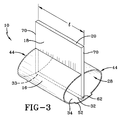
- the device 10 of the present invention for forming a keyhole sipe 12 (FIG. 8) in a tire tread 14 includes an elongated body member 16 having a blade 18 extending in a direction away therefrom and substantially along the length (I) thereof.
- the blade 18 includes a distal end defining an edge 20 and preferably is composed of a metal or metal alloy, such as steel, aluminum, brass, and the like.
- a metal or metal alloy such as steel, aluminum, brass, and the like.
- other materials may be equally suitable for forming the blade 18, for example, a high temperature or heat-resistant plastic material.
- the body member 16 is composed of a deformable material in order to provide low stress on the tread 14 when a slit 24 (FIG. 8) of the keyhole sipe 12 is pulled around the body member 16 during removal of the tread 14 from a mold 26 (FIGS. 4 and 5) as further discussed below.
- This deformable material includes a metal, such as aluminum, steel, and the like, or metal alloy, preferably having a desired elastic deformation.
- the deformable material also may be an elastic material, such as a synthetic or natural rubber, or a shape memory material, such as a shape memory polymer or alloy (e.g. Ni-Ti).
- the deformable material preferably has an elastic property so that the body member 16 can recover its original pre-deformed shape, it should be understood that the deformable material may be devoid of this elastic property.
- the blade 18 is secured to the body member 16, such as by welding.
- any other means commonly known in the art such as an adhesive, male/female mating portions, and the like, may be used to join the blade 18 and the body member 16.
- the blade 18 also may be integrally formed with the body member 16.
- the body member 16 further includes a cavity 28 extending therethrough along the length (I) thereof.
- a stiffening member 32 is securely fixed in position within the cavity 28 and extends substantially along the length (I) of the body member.
- the stiffening member 32 defines a bar secured within the cavity 28 to an inner surface 34 of the body member 16 in a position substantially opposite the blade 18 to provide a desired rigidity to the deformable body member 16, thereby limiting flexion along its length (I) under the stress generated during the molding process after the mold 26 is closed, wherein the stress is transmitted through the rubber formulation as discussed below.
- stiffening member 32 may be provided separately and inserted through the cavity 28, after the body member 16 has been secured within the mold 26, with the ends 62 of the stiffening member 32 being in contact with the tread mold 26, thereby securely positioning the stiffening member 32 within the cavity 28 substantially adjacent an inner surface 34 of the body member 16.
- a proximal end 33 of the blade 18 of the device 10 extends into the cavity 28 to substantially adjacent the inner surface 34 of the body member 16, and substantially along the length (I) thereof, the stiffening member 32 being defined by the proximal end 33 of the blade 18 and further understood as being securely fixed in position within the body member 16. Accordingly, the proximal end 33 of the blade 18 provides a desired rigidity to the body member 16, thereby limiting flexion along the length (I) thereof under the stress generated during the molding process after the mold 26 is closed, wherein the stress is transmitted through the the rubber formulation.
- FIG. 3 shows that the proximal end 33 of the blade 18 may come into contact with the inner surface 34 of the body member 16.
- the stiffening member 32 may include a metal, such as steel or aluminum, or a metal alloy. It should be understood that the stiffening member 32 also may be formed of a plastic material, preferably, a heat-resistant plastic material. The stiffening member 32 advantageously is no greater in width (w 1 ) than the thickness (t) of the blade 18 to allow for easy removal of the formed tread 14 from the mold 26. In addition, although represented as a bar in FIGS. 1 and 5, it should be understood that the stiffening member 32 may take on any number of shapes and configurations, including tubular, rectangular, and the like.
- the thickness (t) of the blade 18 should be 0.3 to 2.0 mm, advantageously, 0.5 to 1.0 mm, and the body member 16 has a width (w 2 ) of 3-12 mm, advantageously, 4-11 mm, more advantageously 5-10 mm, for forming the keyhole sipe 12 in the tread 14.
- the height (h 1 ) of the blade 18 may vary but preferably is 3-6 mm while the height (h 2 ) of the body member 16 similarly may vary but also preferably is 3-6 mm.
- the device 10 for forming a keyhole sipe 12 is to be placed within the mold 26 (shown in partial) for molding the tread 14 which may be intended for either a new or re-treaded tire (not shown). More specifically, the mold 26 includes a plurality of raised portions 36 with a channel 38 therebetween. Side walls 40 of the raised portions 36 are provided with cooperating grooved areas 42 including slots 45. The grooved areas 42 with slots 45 are shaped to receive an end 44 of the device 10, which includes an end 70 of the blade 18. A slot 46 also is provided within a surface 64 of each channel 38. The slot 46 cooperates with the slot 45 of the corresponding grooved areas 42 and is adapted to securely receive the edge 20 of the blade 18.
- each grooved area 42 further includes a stop 48 which is incorporated into the mold 26 and adapted to abut against an end 62 of the stiffening member 32 when the device 10 is inserted therein to help prevent flexion, or deformation, of the body member 16 during formation of the keyhole sipe 12.
- the stops 48 are not needed for the devices 10 shown in FIGS. 3 and 5.
- the device 10 of FIG. 5, which further includes a separate stiffening member 32, is inserted and securely fixed in position within the cavity 28 as further discussed below.
- the device 10 further is provided with optional flanges 52 extending outwardly from the top 54 of the body member 16 at a location opposite the blade 18. These flanges 52 are adapted to abut against the top surface 58 of the raised portions 36 to further help prevent flexion, or deformation, of the body member 16 during formation of the keyhole sipe 12. These flanges 52 may be composed of the same deformable material as the body member 16, as above described, and are secured thereto such as by welding. In addition, any other means known in the art, such as an adhesive, and the like, may be used to join the flanges 52 and the body member 16. The flanges 52 also may be integrally formed with the body member 16.
- each of the ends 44 of the device 10, including the ends 70 (FIG. 1) of the blade 18, respectively, is secured, such as by friction fit or by being wedged, within one of the grooved areas 42 and corresponding slot 45 so that the device 10 extends across the width of the channel 38 between raised portions 36.
- the ends 62 of the stiffening member 32 abut against the stops 48 while the flanges 52 abut against the top surface 58 of the raised portion 36.
- the stops 48 are excluded for insertion of the devices 10 shown in FIGS. 3 and 5.
- the edge 20 of the blade 18 is securely received in slot 46 within the surface 64 of the channel 38.
- the edge 20 of the blade 18 may be secured therein by any means known in the art, such as by being adhesively secured therein, retained by friction fit or wedged therein, and the like.
- the device of FIG. 3 also is similarly inserted into the mold 26 as discussed above.
- the stiffening member or bar 32 of FIG. 1 may be utilized in conjunction with the blade 18 of FIG. 3 having the proximal end 33 extending into the cavity 28 wherein the proximal end 33 may be positioned at least substantially adjacent the bar 32 thereby permitting removal of the stops 48 in the mold 26 of FIGS. 4 and 4A.
- the device 10 of FIG. 5, with separate stiffening member 32, and its placement into mold 26 is discussed next.
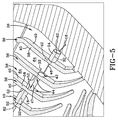
- FIG. 5 shows mold 26 for molding a tire tread 14 wherein the stiffening member 32 is provided separately from the device 10 and securely fixed in position within the cavity 28 (See FIGS. 1 and 3) of the body member 16 by having the ends 62 thereof secured within opposing raised portions 36.
- the body member 28 and blade 18 similarly are secured (as described above), such as by friction fit or by being wedged, within one of the grooved areas 42 and corresponding slot 45 so that the body member 16 extends across the width of the channel 38 between raised portions 36.
- the edge 20 of the blade 18 again may be secured therein by any means known in the art such as by being adhesively secured therein, retained by friction fit or wedged therein, and the like.
- the stiffening member 32 then is inserted through raised portion 36, through the cavity 28 along the length (I) of the body member 16 (as represented by arrow 47), and then secured within opposing raised portion 36 so that the stiffening member 32 is securely fixed in position within the cavity 28 substantially adjacent the inner surface 34 of the body member 16 in a position opposite the blade 18. Accordingly, the stiffening member 32 provides a desired rigidity to the body member 16, thereby limiting flexion along the length (I) thereof under the stress generated during the molding process after the mold 26 is closed, wherein the stress is transmitted through the the rubber formulation as discussed below.
- the device 10, i.e . the slot 46 and corresponding groove 42 with slot 45, of the present invention may be oriented at any desired angle, advantageously, at a 60-90° angle, and more advantageously, at a 75-90° angle relative to the surface 64 of the channel 38 for forming the keyhole sipe 12 for optimal worn groove hydroplaning performance. It should be understood that any number of cooperating grooved areas 42 with slots 45 may be provided on the side walls 40 of raised portions 36 for receiving the device 10 of the present invention.
- the rubber formulation for the tread 14 is introduced therein.
- the mold 26 is closed and the tread 14 allowed time to cure.
- the stiffening member 32 provides a desired rigidity to the deformable body member 16, thereby limiting flexion inwardly of the body member 16 along its length (I) proximate the stiffening member 32 under the stress of the rubber formulation when the mold 26 is closed. More specifically, the stiffening member 32 resists the forces applied, during the molding process, which generally imposes pressure outwardly from the interior of the green tread 14 toward the boundary defined by the surface 64 of the mold 26. Finally, after curing, the mold 26 is opened and the tread 14 removed therefrom.
- the body member 16 compresses, or deforms, inwardly along its sides 68, thereby elongating to provide low stress on the tread 14 when the slit 24 of the formed keyhole sipe 12 is pulled around the body member 16.
- the edge 20 and ends 70 of the blade 18 remain secured within the mold 26 during this deformation.
- the material of the deformed body member 16 includes an elastic property, the body 16 will return to its pre-deformed condition and the molding process may be repeated anew. Otherwise, the device(s) 10 will need to be replaced.
- the formation of the tread 14 has been illustrated with respect to the device 10 of FIG. 1, it should be understood by one skilled in the art that the devices 10 of FIGS. 3 and 5 perform in the same manner to produce the formed tread 14 as shown in FIGS. 7 and 8 and further described below.
- the formed tread 14 includes a plurality of keyhole sipes 12 each having the slit 24 defining an opening 72 at a surface 74 of the tread 14 and a passage 76 formed therebelow that cooperates with the slit 24.
- the raised portions 36 of the mold 26 provide the tread 14 with grooves 80 while the channel 38 provides a tread block 82 with the keyhole sipes 12 extending from one groove 80 to the other groove 80 across the width of the block 82.
- the slit 24 of the formed keyhole sipe 12 has a width (w 3 ) of 0.3 to 2.0 mm, advantageously, 0.5 to 1.0 mm, and the passage 76 has a width (w 4 ) of 3-12 mm, advantageously, 4-11 mm, more advantageously 5-10 mm, thereby providing a more desirable wet traction performance for a tire, and a reduction in air transfer noise.
- the device 10 of the present invention for molding keyhole sipes 12 larger in size, i.e . sipes 12 having a wider passage 76, than currently being formed in treads 14, which avoids damaging the tread 14 during formation and removal thereof from the mold 26.
Landscapes
- Engineering & Computer Science (AREA)
- Mechanical Engineering (AREA)
- Moulds For Moulding Plastics Or The Like (AREA)
- Heating, Cooling, Or Curing Plastics Or The Like In General (AREA)
Abstract
Description
- The present invention pertains generally to devices intended to equip molds for molding objects made of rubber and, more particularly, to devices for molding keyhole sipes in the treads of pneumatic tires.
- As a tire wears down its tread, the volume of the grooves therein is reduced, which can lead to poor hydroplaning performance. To increase the worn groove volume, keyhole sipes, i.e. sunken tire grooves having a keyhole cross-section, are incorporated into the tread. Each keyhole sipe typically includes a slit defining an opening at a surface of the tread and a passage formed therebelow that cooperates with the slit to increase the tread's worn groove volume.
- To form these keyhole sipes, molds are equipped with sipe-forming devices, which are well known in the art of tire manufacture. The molds may be used for producing a tread member only, as for use in retreading a previously cured tire, or for forming a tread design on a green tire. Such sipe-forming devices conventionally include a base, or body member, provided with a blade that typically is made from a running length or strip of a metallic material such as steel, stainless steel, or brass. The blade is shaped to form the slit in the tire tread while the body member produces the passage underneath the tread surface, thereby producing the keyhole-shaped cross-section of the sipe. In forming the keyhole sipe, the molding device is positioned within a channel in the mold so that the blade cooperates with a surface of the channel and the body member is spaced apart therefrom, respectively, to form the slit in the tire and the passage underneath the tread surface. Next, the rubber formulation is introduced into the mold. The mold then is closed and the tread allowed time to cure. Finally, the mold is opened and the tread removed therefrom with the molding device having formed the keyhole sipe therein.
- One drawback with current molding devices includes an inability of the body member to deform, or compress, during tread removal thereby placing high stress on the tread when the slit of the formed keyhole sipe is pulled around the body member of the molding device. Notably, if the body member exceeds a certain size parameter, i.e. a certain width, there is a high likelihood that the tread will be damaged, such as by being torn, during removal from the mold. Deformable body members have been proposed in an effort to replace non-deformable members to reduce the stress on the tread during removal thereof. However, one drawback with these types of current devices includes the tendency of the deformable body member to inwardly flex, or collapse, along its length under the stress of the rubber formulation when the mold is closed during the molding process. This inward distortion damages the tread during tread formation by producing a misshapen keyhole, i.e. a misshapen passage.
- Because of the above limitations, current molding devices are designed according to certain size parameters to avoid damaging the tire tread during tread formation. More specifically, the body members of current molding devices typically have a width not greater than 3.5 mm while the blade typically is not greater than 0.8 mm in thickness. Since a larger keyhole sipe, i.e. one having a wider passage, would be better able to provide wet traction of the tire and be better able to reduce air transfer noise, the tire industry has long felt a need for a molding device having a wider body member that can produce a larger-sized keyhole sipe without causing damage to the tread during the molding process.
- Accordingly, there is a need for an improved device for molding keyhole sipes larger in size, i.e. sipes having a wider passage, than currently being formed in treads that will provide a properly shaped keyhole sipe and avoid damaging the tread during formation and removal thereof from the mold, thereby providing the worn tire tread greater hydroplaning performance.
- The present invention provides for an improved device for molding keyhole sipes in a tire tread that does not have the drawbacks of the molding devices currently employed.
- To this end, the device includes an elongated body member having a blade extending in a direction away therefrom and substantially along the length thereof. The blade includes a distal end defining an edge and generally is composed of a metal or metal alloy. The body member is composed of a deformable material to provide low stress on the tread when the slit of the formed keyhole sipe is pulled around the body member during removal of the tread from the mold. This deformable material may include an elastic material, a shape memory material, or a metal or metal alloy. The body member is configured to deform upon removal of the cured tread member, and not during actual molding. The blade may be integrally formed with the body member or secured thereto by means commonly known in the art.
- The body member further includes a cavity extending therethrough along the length thereof. A stiffening member is securely fixed in position within the cavity and extends substantially along the length of the body member to provide a desired rigidity, thereby limiting flexion along the length of the body member under the stress of the rubber formulation when a tread mold is closed during the molding process. The stiffening member may include a metal or metal alloy, or a plastic material.
- In an exemplary embodiment, the stiffening member defines a bar which is secured to an inner surface of the body member in a position substantially opposite the blade. In another exemplary embodiment, the stiffening member, e.g. a bar, is separately provided. After a tread mold has received the body member, this stiffening member is inserted within the cavity with its ends being in contact with the tread mold to securely position the stiffening member within the cavity substantially adjacent an inner surface of the body member, preferably in a position opposite the blade, and along the length of the body member. In yet another exemplary embodiment, a proximal end of the blade extends within the cavity to a position at least substantially adjacent the inner surface of the body member and substantially along the length of the body member, the stiffening member being defined by the proximal end of the blade. In this embodiment, the proximal end of the blade may contact the inner surface of the body member. In each case, the stiffening member provides a desired rigidity to the body member, thereby limiting flexion of the body member along the length thereof under the stress of the rubber formulation when a tread mold is closed during the molding process.
- The blade is provided with a thickness of 0.3 to 2.0 mm, advantageously 0.5 to 1.0 mm, and the body member includes an oversized width of 3-12 mm, advantageously 4-11 mm, more advantageously 5-10 mm, so as to form an oversized passage in the keyhole sipe in the tire tread.
- The device for producing the keyhole sipe is adapted to be placed within a mold for molding the tread, which may be intended for either a new or re-treaded tire. The mold is provided with at least two raised portions having a channel therebetween. In designing the tire tread, the raised or positive portion of the mold corresponds to a channel in the cured tread, such as for conducting water away from the road-contacting surface of the tire. Similarly, the channel in the mold corresponds to a tread block, the outermost portion thereof in the cured tread making contact with the road surface. Each raised portion includes a grooved area adapted to receive each of the ends of the device.
- A slot also is provided within a surface of the channel. The slot cooperates with corresponding grooved areas and is adapted to receive the edge of the blade. A stop optionally may be provided in each groove, the slot being adapted to abut against an end of the stiffening member when the device is inserted therein, thereby helping prevent flexion, or deformation, of the body member during formation of the keyhole sipe. Accordingly, each end of the device is secured within one of the grooved areas so that the device extends across the width of the channel between the raised portions with the edge of the blade being securely received within the surface of the channel.
- When the desired number of devices with stiffening members are appropriately securely situated in the mold, the rubber formulation for the tread is introduced therein. The mold then is closed and the tread allowed time to cure. During this process, the stiffening member provides a desired rigidity to the deformable body member, thereby limiting flexion thereof along its length proximate the stiffening member under the stress of the rubber formulation when the mold is closed. Finally, the mold is opened and the tread removed therefrom wherein the body member compresses, or deforms, inwardly along its sides, thereby elongating to provide low stress on the tread when the slit of the formed keyhole sipe is pulled around the body member.
- The formed tread includes at least one keyhole sipe having a slit defining an opening at a surface of the tread and a passage, being properly formed, below the surface that cooperates with the slit to increase the tread's worn groove volume. Consequently, the slit is formed having a width of 0.3 to 2.0 mm, advantageously 0.5 to 1.0 mm, and the passage is formed having a width of 3-12 mm, advantageously 4-11 mm, more advantageously 5-10 mm, so as to provide a more desirable wet traction for a tire, and a reduction in air transfer noise. Accordingly, dimensions of the keyhole sipe, particularly the passage, exceed the maximum limits of current sipes.
- By virtue of the foregoing, there is thus provided an improved device for molding keyhole sipes larger in size, i.e. sipes having a wider passage, than currently being formed in treads that avoids damaging the tread during formation and removal thereof from the mold.
- The features and objectives of the present invention will become more readily apparent from the following Detailed Description taken in conjunction with the accompanying drawings.
- The accompanying drawings illustrate embodiments of the invention.
- FIG. 1 is an enlarged perspective view of one embodiment of the device of the present invention for molding a keyhole sipe in a tire tread;
- FIG. 2 is a cross-sectional view of FIG. 1 taken along lines 2-2;
- FIG. 3 is another embodiment of the device for molding a keyhole sipe in a tire tread;
- FIG. 4 is a cut-away perspective view of a mold for molding a tire tread that is equipped with the device of FIG. 1;
- FIG. 4A is an enlarged view of the incircle portion of FIG. 4 showing the grooved area;
- FIG. 5 is a cut-away perspective view of a mold for molding a tire tread that is equipped with another embodiment of the device in accordance with the present invention.
- FIGS. 6A-6D are cross-sectional views of FIG. 4 illustrating the molding process including removal of the tread from the mold;
- FIG. 7 is a perspective view of the formed tread from FIG. 6D; and
- FIG. 8 is a cross-sectional view of the tread of FIG. 6 taken along lines 8-8.
- As best shown in FIGS. 1-3, and 5, the
device 10 of the present invention for forming a keyhole sipe 12 (FIG. 8) in a tire tread 14 (FIG. 7) includes anelongated body member 16 having ablade 18 extending in a direction away therefrom and substantially along the length (I) thereof. Theblade 18 includes a distal end defining anedge 20 and preferably is composed of a metal or metal alloy, such as steel, aluminum, brass, and the like. However, it should be understood that other materials may be equally suitable for forming theblade 18, for example, a high temperature or heat-resistant plastic material. - The
body member 16 is composed of a deformable material in order to provide low stress on thetread 14 when a slit 24 (FIG. 8) of thekeyhole sipe 12 is pulled around thebody member 16 during removal of thetread 14 from a mold 26 (FIGS. 4 and 5) as further discussed below. This deformable material includes a metal, such as aluminum, steel, and the like, or metal alloy, preferably having a desired elastic deformation. The deformable material also may be an elastic material, such as a synthetic or natural rubber, or a shape memory material, such as a shape memory polymer or alloy (e.g. Ni-Ti). While the deformable material preferably has an elastic property so that thebody member 16 can recover its original pre-deformed shape, it should be understood that the deformable material may be devoid of this elastic property. Theblade 18 is secured to thebody member 16, such as by welding. In addition, any other means commonly known in the art, such as an adhesive, male/female mating portions, and the like, may be used to join theblade 18 and thebody member 16. Theblade 18 also may be integrally formed with thebody member 16. - The
body member 16 further includes acavity 28 extending therethrough along the length (I) thereof. As shown in FIGS. 1, 3 and 5, a stiffeningmember 32 is securely fixed in position within thecavity 28 and extends substantially along the length (I) of the body member. With specific reference to FIG. 1, the stiffeningmember 32 defines a bar secured within thecavity 28 to aninner surface 34 of thebody member 16 in a position substantially opposite theblade 18 to provide a desired rigidity to thedeformable body member 16, thereby limiting flexion along its length (I) under the stress generated during the molding process after themold 26 is closed, wherein the stress is transmitted through the rubber formulation as discussed below. Although the stiffeningmember 32 shown in FIG. 1 is secured to aninner surface 34 of thebody member 16, it should be understood, as shown in FIG. 5 and further described below, that the stiffeningmember 32 may be provided separately and inserted through thecavity 28, after thebody member 16 has been secured within themold 26, with theends 62 of the stiffeningmember 32 being in contact with thetread mold 26, thereby securely positioning the stiffeningmember 32 within thecavity 28 substantially adjacent aninner surface 34 of thebody member 16. - In another embodiment, as shown in FIG. 3, a
proximal end 33 of theblade 18 of thedevice 10 extends into thecavity 28 to substantially adjacent theinner surface 34 of thebody member 16, and substantially along the length (I) thereof, the stiffeningmember 32 being defined by theproximal end 33 of theblade 18 and further understood as being securely fixed in position within thebody member 16. Accordingly, theproximal end 33 of theblade 18 provides a desired rigidity to thebody member 16, thereby limiting flexion along the length (I) thereof under the stress generated during the molding process after themold 26 is closed, wherein the stress is transmitted through the the rubber formulation. Although shown in FIG. 3 as being substantially adjacent theinner surface 34 of thebody member 16, it should be understood that theproximal end 33 of theblade 18 may come into contact with theinner surface 34 of thebody member 16. - The stiffening
member 32 may include a metal, such as steel or aluminum, or a metal alloy. It should be understood that the stiffeningmember 32 also may be formed of a plastic material, preferably, a heat-resistant plastic material. The stiffeningmember 32 advantageously is no greater in width (w1) than the thickness (t) of theblade 18 to allow for easy removal of the formedtread 14 from themold 26. In addition, although represented as a bar in FIGS. 1 and 5, it should be understood that the stiffeningmember 32 may take on any number of shapes and configurations, including tubular, rectangular, and the like. - With reference to FIGS. 1-3 and 5, the thickness (t) of the
blade 18 should be 0.3 to 2.0 mm, advantageously, 0.5 to 1.0 mm, and thebody member 16 has a width (w2) of 3-12 mm, advantageously, 4-11 mm, more advantageously 5-10 mm, for forming thekeyhole sipe 12 in thetread 14. The height (h1) of theblade 18 may vary but preferably is 3-6 mm while the height (h2) of thebody member 16 similarly may vary but also preferably is 3-6 mm. - As best shown in FIGS. 4 and 4A, the
device 10 for forming akeyhole sipe 12 is to be placed within the mold 26 (shown in partial) for molding thetread 14 which may be intended for either a new or re-treaded tire (not shown). More specifically, themold 26 includes a plurality of raisedportions 36 with achannel 38 therebetween.Side walls 40 of the raisedportions 36 are provided with cooperatinggrooved areas 42 includingslots 45. Thegrooved areas 42 withslots 45 are shaped to receive anend 44 of thedevice 10, which includes anend 70 of theblade 18. Aslot 46 also is provided within asurface 64 of eachchannel 38. Theslot 46 cooperates with theslot 45 of the correspondinggrooved areas 42 and is adapted to securely receive theedge 20 of theblade 18. For the insertion of thedevice 10 of FIG. 1, eachgrooved area 42 further includes astop 48 which is incorporated into themold 26 and adapted to abut against anend 62 of the stiffeningmember 32 when thedevice 10 is inserted therein to help prevent flexion, or deformation, of thebody member 16 during formation of thekeyhole sipe 12. It should be understood by one skilled in the art that thestops 48 are not needed for thedevices 10 shown in FIGS. 3 and 5. Thedevice 10 of FIG. 5, which further includes aseparate stiffening member 32, is inserted and securely fixed in position within thecavity 28 as further discussed below. - The
device 10 further is provided withoptional flanges 52 extending outwardly from the top 54 of thebody member 16 at a location opposite theblade 18. Theseflanges 52 are adapted to abut against thetop surface 58 of the raisedportions 36 to further help prevent flexion, or deformation, of thebody member 16 during formation of thekeyhole sipe 12. Theseflanges 52 may be composed of the same deformable material as thebody member 16, as above described, and are secured thereto such as by welding. In addition, any other means known in the art, such as an adhesive, and the like, may be used to join theflanges 52 and thebody member 16. Theflanges 52 also may be integrally formed with thebody member 16. - Accordingly, with further reference to FIGS. 4 and 4A, to equip the
mold 26 with thedevice 10, each of theends 44 of thedevice 10, including the ends 70 (FIG. 1) of theblade 18, respectively, is secured, such as by friction fit or by being wedged, within one of thegrooved areas 42 and correspondingslot 45 so that thedevice 10 extends across the width of thechannel 38 between raisedportions 36. Specifically, for the insertion of thedevice 10 of FIG. 1, the ends 62 of the stiffeningmember 32 abut against thestops 48 while theflanges 52 abut against thetop surface 58 of the raisedportion 36. As stated above, it should be understood by one skilled in the art that thestops 48 are excluded for insertion of thedevices 10 shown in FIGS. 3 and 5. Theedge 20 of theblade 18 is securely received inslot 46 within thesurface 64 of thechannel 38. Theedge 20 of theblade 18 may be secured therein by any means known in the art, such as by being adhesively secured therein, retained by friction fit or wedged therein, and the like. It should be understood by one skilled in the art that the device of FIG. 3 also is similarly inserted into themold 26 as discussed above. In addition, it should be further understood that the stiffening member or bar 32 of FIG. 1 may be utilized in conjunction with theblade 18 of FIG. 3 having theproximal end 33 extending into thecavity 28 wherein theproximal end 33 may be positioned at least substantially adjacent thebar 32 thereby permitting removal of thestops 48 in themold 26 of FIGS. 4 and 4A. Thedevice 10 of FIG. 5, withseparate stiffening member 32, and its placement intomold 26 is discussed next. - FIG. 5 shows
mold 26 for molding atire tread 14 wherein the stiffeningmember 32 is provided separately from thedevice 10 and securely fixed in position within the cavity 28 (See FIGS. 1 and 3) of thebody member 16 by having theends 62 thereof secured within opposing raisedportions 36. Specifically, to equip themold 26 with thedevice 10 including the stiffeningmember 32, thebody member 28 andblade 18 similarly are secured (as described above), such as by friction fit or by being wedged, within one of thegrooved areas 42 and correspondingslot 45 so that thebody member 16 extends across the width of thechannel 38 between raisedportions 36. Theedge 20 of theblade 18 again may be secured therein by any means known in the art such as by being adhesively secured therein, retained by friction fit or wedged therein, and the like. - The stiffening
member 32 then is inserted through raisedportion 36, through thecavity 28 along the length (I) of the body member 16 (as represented by arrow 47), and then secured within opposing raisedportion 36 so that the stiffeningmember 32 is securely fixed in position within thecavity 28 substantially adjacent theinner surface 34 of thebody member 16 in a position opposite theblade 18. Accordingly, the stiffeningmember 32 provides a desired rigidity to thebody member 16, thereby limiting flexion along the length (I) thereof under the stress generated during the molding process after themold 26 is closed, wherein the stress is transmitted through the the rubber formulation as discussed below. - The
device 10, i.e. theslot 46 and correspondinggroove 42 withslot 45, of the present invention may be oriented at any desired angle, advantageously, at a 60-90° angle, and more advantageously, at a 75-90° angle relative to thesurface 64 of thechannel 38 for forming thekeyhole sipe 12 for optimal worn groove hydroplaning performance. It should be understood that any number of cooperatinggrooved areas 42 withslots 45 may be provided on theside walls 40 of raisedportions 36 for receiving thedevice 10 of the present invention. - With further reference to FIGS. 4 and 6A, when the desired number of
devices 10 is securely situated inmold 26, the rubber formulation for thetread 14 is introduced therein. Themold 26 is closed and thetread 14 allowed time to cure. Notably, the stiffeningmember 32 provides a desired rigidity to thedeformable body member 16, thereby limiting flexion inwardly of thebody member 16 along its length (I) proximate the stiffeningmember 32 under the stress of the rubber formulation when themold 26 is closed. More specifically, the stiffeningmember 32 resists the forces applied, during the molding process, which generally imposes pressure outwardly from the interior of thegreen tread 14 toward the boundary defined by thesurface 64 of themold 26. Finally, after curing, themold 26 is opened and thetread 14 removed therefrom. - During removal, as best shown in FIGS. 6B and 6C, the
body member 16 compresses, or deforms, inwardly along itssides 68, thereby elongating to provide low stress on thetread 14 when theslit 24 of the formedkeyhole sipe 12 is pulled around thebody member 16. Theedge 20 and ends 70 of theblade 18 remain secured within themold 26 during this deformation. As best shown in FIG. 6D, aftertread 14 removal, if the material of thedeformed body member 16 includes an elastic property, thebody 16 will return to its pre-deformed condition and the molding process may be repeated anew. Otherwise, the device(s) 10 will need to be replaced. - Although, the formation of the
tread 14 has been illustrated with respect to thedevice 10 of FIG. 1, it should be understood by one skilled in the art that thedevices 10 of FIGS. 3 and 5 perform in the same manner to produce the formedtread 14 as shown in FIGS. 7 and 8 and further described below. - With continuing reference to FIGS. 7 and 8, the formed
tread 14 includes a plurality ofkeyhole sipes 12 each having theslit 24 defining anopening 72 at asurface 74 of thetread 14 and apassage 76 formed therebelow that cooperates with theslit 24. Notably, the raisedportions 36 of themold 26 provide thetread 14 withgrooves 80 while thechannel 38 provides atread block 82 with thekeyhole sipes 12 extending from onegroove 80 to theother groove 80 across the width of theblock 82. Consequently, theslit 24 of the formedkeyhole sipe 12 has a width (w3) of 0.3 to 2.0 mm, advantageously, 0.5 to 1.0 mm, and thepassage 76 has a width (w4) of 3-12 mm, advantageously, 4-11 mm, more advantageously 5-10 mm, thereby providing a more desirable wet traction performance for a tire, and a reduction in air transfer noise. - Accordingly, there is provided the
device 10 of the present invention formolding keyhole sipes 12 larger in size, i.e.sipes 12 having awider passage 76, than currently being formed intreads 14, which avoids damaging thetread 14 during formation and removal thereof from themold 26.
Claims (10)
- A device for forming a keyhole sipe in a tire, comprising:an elongated body member (16) having a blade (18) extending in a direction away therefrom and substantially along the length thereof, the blade (18) including a distal end (44) defining an edge, the body member (16) further including a cavity (28) extending therethrough along the length thereof;characterized in that the body member (16) is composed of a deformable material and a stiffening member (32) being securely fixed in position within the cavity (28) and extending substantially along the length of the body member (16) to provide rigidity thereto, thereby limiting flexion of the body member (16).
- The device of claim 1, wherein the stiffening member (32) is secured within the cavity (28) to an inner surface (34) of the body member in a position substantially opposite the blade (18).
- The device of claim 1, wherein the deformable material includes an elastic material, shape memory material, metal, or metal alloy.
- The device of claim 1, wherein the blade (18) includes a thickness of 0.3 to 2.0 mm and the body member (16) includes a width of 3-12 mm.
- The device of claim 1, wherein the body member further includes an inner surface and the blade (18) further includes a proximal end (33) extending into the cavity of the body member to a position at least substantially adjacent the inner surface of the body member, the stiffening member (32) being defined by the proximal end (33) of the blade.
- A mold for molding a tire tread having a keyhole sipe, comprising:at least two raised portions (36) having a channel (38) therebetween, each raised portion including a grooved area (42); andat least one device (10) for forming the keyhole sipe in the tread, the device including opposing ends along the length thereof with each end secured respectively within the grooved areas (42) of each of the raised portions so that the device extends across the width of the channel (38) between the raised portions, the device including an elongated body (16) member having a blade (18) extending in a direction away therefrom and substantially along the length thereof, the blade including a distal end (44) defining an edge secured within a surface of the channel (38), the body member (16) further including a cavity (28) extending therethrough along the length thereof,characterized in that the body member (16) is composed of a deformable material and a stiffening member being securely fixed in position within the cavity (28) and extending substantially along the length of the body member (16) to provide rigidity thereto, thereby limiting flexion of the body member during formation of the keyhole sipe.
- The mold of claim 6, wherein each grooved area (42) further includes a stop (48) adapted to abut against an end of the stiffening member (32) to limit deformation of the body member during formation of the keyhole sipe.
- The mold of claim 6, wherein the body member further includes an inner surface (34) and the stiffening member (32) includes opposing ends with each end being secured within one of the raised portions (36) to securely position the stiffening member within the cavity (28), the stiffening member extending along the length of the body member adjacent the inner surface to provide rigidity thereto.
- A tread for a pneumatic tire, comprising:a plurality of lateral grooves defined in the tread;a plurality of keyhole sipes defined in the tread, each keyhole sipe including a slit defining an opening at a surface of the tread and a passage formed below the surface cooperating with the slit; anda plurality of tread blocks defined by intersections between the keyhole sipes and the lateral grooves,characterized in that the slit of each of the plurality of keyhole sipes has a width of 0.3 to 2.0 mm and the passage of the plurality of keyhole sipes has a width of 4-11 mm.
- The tread of claim 9, wherein the slit further includes a height of 3-6 mm and the passage further includes a height of 3-6 mm.
Applications Claiming Priority (1)
| Application Number | Priority Date | Filing Date | Title |
|---|---|---|---|
| US64038604P | 2004-12-30 | 2004-12-30 |
Publications (3)
| Publication Number | Publication Date |
|---|---|
| EP1676695A2 true EP1676695A2 (en) | 2006-07-05 |
| EP1676695A3 EP1676695A3 (en) | 2013-06-05 |
| EP1676695B1 EP1676695B1 (en) | 2016-04-20 |
Family
ID=36177834
Family Applications (1)
| Application Number | Title | Priority Date | Filing Date |
|---|---|---|---|
| EP05112810.6A Ceased EP1676695B1 (en) | 2004-12-30 | 2005-12-22 | Mold with a device for molding a keyhole sipe in a tire tread |
Country Status (3)
| Country | Link |
|---|---|
| US (1) | US7661942B2 (en) |
| EP (1) | EP1676695B1 (en) |
| JP (1) | JP4754966B2 (en) |
Cited By (13)
| Publication number | Priority date | Publication date | Assignee | Title |
|---|---|---|---|---|
| EP1935602A1 (en) * | 2006-12-21 | 2008-06-25 | The Goodyear Tire & Rubber Company | A flexible molding device for manufacturing a sunken groove in a tire tread |
| EP1935601A1 (en) | 2006-12-21 | 2008-06-25 | The Goodyear Tire & Rubber Company | Flexible molding device for manufacturing a sunken groove in a tire tread |
| EP1938956A1 (en) | 2006-12-21 | 2008-07-02 | The Goodyear Tire & Rubber Company | Flexible molding device for manufacturing a sunken groove or surface tie bar in a tire tread |
| EP1938939A1 (en) * | 2006-12-21 | 2008-07-02 | The Goodyear Tire & Rubber Company | Flexible enrobed molding device for manufacturing a sunken groove in a tire tread |
| EP1938938A1 (en) * | 2006-12-21 | 2008-07-02 | The Goodyear Tire & Rubber Company | Flexible molding device for molding a sunk groove, a sunk blade, and a large keyhole sipe in a tire tread |
| EP1935671A3 (en) * | 2006-12-21 | 2009-03-25 | The Goodyear Tire & Rubber Company | Pneumatic tire |
| EP1935670A3 (en) * | 2006-12-21 | 2009-03-25 | The Goodyear Tire & Rubber Company | Pneumatic tire |
| US20100072678A1 (en) * | 2006-10-12 | 2010-03-25 | Daimler Ag | Method and Apparatus for Producing a Composite Component |
| WO2010063750A1 (en) * | 2008-12-05 | 2010-06-10 | Societe De Technologie Michelin | Tire tread comprising incisions and recesses |
| EP2311655A1 (en) * | 2009-10-14 | 2011-04-20 | Continental Reifen Deutschland GmbH | Run strip profile of a vehicle tyre |
| WO2014001069A1 (en) | 2012-06-25 | 2014-01-03 | Continental Reifen Deutschland Gmbh | Tread profile of a vehicle tyre |
| CN108340740A (en) * | 2017-01-25 | 2018-07-31 | 韩国轮胎株式会社 | The solid type tyre surface notch of tire |
| DE102017209903A1 (en) | 2017-06-13 | 2018-12-13 | Continental Reifen Deutschland Gmbh | Tread pattern of a vehicle tire for use on wintry surfaces |
Families Citing this family (7)
| Publication number | Priority date | Publication date | Assignee | Title |
|---|---|---|---|---|
| US7793692B2 (en) * | 2005-10-31 | 2010-09-14 | The Goodyear Tire & Rubber Company | Pneumatic tire tread having sipe that devolves into groove as tread wears |
| US8632715B2 (en) * | 2008-08-31 | 2014-01-21 | Michelin Recherche Et Technique S.A. | Contoured flat mold |
| JP5438828B2 (en) * | 2009-06-29 | 2014-03-12 | ミシュラン ルシェルシュ エ テクニーク ソシエテ アノニム | Methods and configurations for improved snow static friction, highway wear, and off-road performance |
| US9616716B2 (en) | 2011-12-14 | 2017-04-11 | Bridgestone Americas Tire Operations, Llc | Three dimensional sipe |
| JP5723348B2 (en) * | 2012-10-11 | 2015-05-27 | 住友ゴム工業株式会社 | Mold pin, tire mold to which mold pin is attached, and method for manufacturing pneumatic tire using the same |
| FR2998511B1 (en) * | 2012-11-29 | 2014-12-26 | Michelin & Cie | TIRE TREAD FOR SNOW TIRES HAVING INCISIONS AND CAVITIES |
| FR3014734B1 (en) * | 2013-12-12 | 2016-08-12 | Michelin & Cie | MOLDING ELEMENT COMPRISING A PARTICULAR ASSEMBLY MEANS |
Citations (6)
| Publication number | Priority date | Publication date | Assignee | Title |
|---|---|---|---|---|
| JPH04215507A (en) | 1990-12-14 | 1992-08-06 | Jinbo:Kk | Manufacture of tire blade to cope with frozen road surface |
| US5385189A (en) | 1991-11-01 | 1995-01-31 | Bridgestone Corporation | Pneumatic tire with paired sides in the tread |
| JPH0825362A (en) | 1994-07-15 | 1996-01-30 | Bridgestone Corp | Tire vulcanizing mold and method for manufacturing metal blade used in tire vulcanizing mold |
| JPH0938978A (en) | 1995-08-02 | 1997-02-10 | Bridgestone Corp | Flask-shaped blade for tire vulcanizing mold and production thereof |
| EP0873851A1 (en) | 1997-04-24 | 1998-10-28 | Compagnie Générale des Etablissements MICHELIN-MICHELIN & CIE | Mould element for moulding a pattern on a tyre tread band |
| WO2002038399A2 (en) | 2000-11-13 | 2002-05-16 | Societe De Technologie Michelin | Tyre running tread and moulding element of a mould for such a tread |
Family Cites Families (13)
| Publication number | Priority date | Publication date | Assignee | Title |
|---|---|---|---|---|
| US1625644A (en) * | 1927-04-19 | Manufacture of cushion tires | ||
| US2779060A (en) * | 1953-05-13 | 1957-01-29 | Firestone Tire & Rubber Co | Tire mold |
| US2736924A (en) * | 1953-10-01 | 1956-03-06 | Morris Bean & Company | Bladed tire molds and method |
| US3115919A (en) * | 1962-04-27 | 1963-12-31 | Armstrong Rubber Co | Tire tread |
| FR1590861A (en) * | 1967-11-07 | 1970-04-20 | ||
| US4154564A (en) * | 1968-06-09 | 1979-05-15 | Dunlop Holdings Limited | Tire molding matrix |
| JPS61160303A (en) * | 1985-01-04 | 1986-07-21 | Seiko Epson Corp | Pneumatic tire |
| JP2754040B2 (en) * | 1989-05-30 | 1998-05-20 | 東洋ゴム工業株式会社 | Mold for pneumatic tire molding |
| US6408911B1 (en) * | 1995-06-08 | 2002-06-25 | Bridgestone Corporation | Studless pneumatic tire including block-shaped island portions each having sipes |
| JP3715008B2 (en) * | 1995-11-17 | 2005-11-09 | 株式会社ブリヂストン | Tire vulcanizing mold and sipe blade manufacturing method used for tire vulcanizing mold |
| US6264453B1 (en) * | 1997-10-27 | 2001-07-24 | The Goodyear Tire & Rubber Company | Article and method for composite tire mold blades |
| JP2003211455A (en) * | 2002-01-17 | 2003-07-29 | Bridgestone Corp | Vulcanizing mold |
| US20040055683A1 (en) | 2002-09-19 | 2004-03-25 | Feider Georges Gaston | Truck steer tire, a mold and a method of molding |
-
2005
- 2005-07-21 US US11/186,612 patent/US7661942B2/en active Active
- 2005-12-22 EP EP05112810.6A patent/EP1676695B1/en not_active Ceased
- 2005-12-28 JP JP2005379443A patent/JP4754966B2/en not_active Expired - Fee Related
Patent Citations (6)
| Publication number | Priority date | Publication date | Assignee | Title |
|---|---|---|---|---|
| JPH04215507A (en) | 1990-12-14 | 1992-08-06 | Jinbo:Kk | Manufacture of tire blade to cope with frozen road surface |
| US5385189A (en) | 1991-11-01 | 1995-01-31 | Bridgestone Corporation | Pneumatic tire with paired sides in the tread |
| JPH0825362A (en) | 1994-07-15 | 1996-01-30 | Bridgestone Corp | Tire vulcanizing mold and method for manufacturing metal blade used in tire vulcanizing mold |
| JPH0938978A (en) | 1995-08-02 | 1997-02-10 | Bridgestone Corp | Flask-shaped blade for tire vulcanizing mold and production thereof |
| EP0873851A1 (en) | 1997-04-24 | 1998-10-28 | Compagnie Générale des Etablissements MICHELIN-MICHELIN & CIE | Mould element for moulding a pattern on a tyre tread band |
| WO2002038399A2 (en) | 2000-11-13 | 2002-05-16 | Societe De Technologie Michelin | Tyre running tread and moulding element of a mould for such a tread |
Cited By (28)
| Publication number | Priority date | Publication date | Assignee | Title |
|---|---|---|---|---|
| US20100072678A1 (en) * | 2006-10-12 | 2010-03-25 | Daimler Ag | Method and Apparatus for Producing a Composite Component |
| US8241552B2 (en) * | 2006-10-12 | 2012-08-14 | Daimler Ag | Method and apparatus for producing a composite component |
| EP1935671A3 (en) * | 2006-12-21 | 2009-03-25 | The Goodyear Tire & Rubber Company | Pneumatic tire |
| EP1938939A1 (en) * | 2006-12-21 | 2008-07-02 | The Goodyear Tire & Rubber Company | Flexible enrobed molding device for manufacturing a sunken groove in a tire tread |
| EP1938938A1 (en) * | 2006-12-21 | 2008-07-02 | The Goodyear Tire & Rubber Company | Flexible molding device for molding a sunk groove, a sunk blade, and a large keyhole sipe in a tire tread |
| US7507078B2 (en) | 2006-12-21 | 2009-03-24 | The Goodyear Tire & Rubber Company | Flexible molding device for molding a sunk groove, a sunk blade, and a large keyhole sipe in tire tread |
| CN101254633B (en) * | 2006-12-21 | 2010-09-08 | 固特异轮胎和橡胶公司 | Flexible molding device for molding sinkers, blades and large keyhole patterns in the crown |
| EP1935670A3 (en) * | 2006-12-21 | 2009-03-25 | The Goodyear Tire & Rubber Company | Pneumatic tire |
| US7544054B2 (en) | 2006-12-21 | 2009-06-09 | The Goodyear Tire & Rubber Company | Flexible molding device for manufacturing a sunken groove in a tire tread |
| US7544053B2 (en) | 2006-12-21 | 2009-06-09 | The Goodyear Tire And Rubber Company | Flexible molding device for manufacturing a sunken groove or surface tie bar in a tire tread |
| US7566213B2 (en) | 2006-12-21 | 2009-07-28 | The Goodyear Tire & Rubber Company | Flexible enrobed molding device for manufacturing a sunken groove in a tire tread |
| US7575424B2 (en) | 2006-12-21 | 2009-08-18 | The Goodyear Tire & Rubber Company | Flexible molding device for manufacturing a sunken groove in a tire tread |
| EP1938956A1 (en) | 2006-12-21 | 2008-07-02 | The Goodyear Tire & Rubber Company | Flexible molding device for manufacturing a sunken groove or surface tie bar in a tire tread |
| EP1935601A1 (en) | 2006-12-21 | 2008-06-25 | The Goodyear Tire & Rubber Company | Flexible molding device for manufacturing a sunken groove in a tire tread |
| EP1935602A1 (en) * | 2006-12-21 | 2008-06-25 | The Goodyear Tire & Rubber Company | A flexible molding device for manufacturing a sunken groove in a tire tread |
| FR2939364A1 (en) * | 2008-12-05 | 2010-06-11 | Michelin Soc Tech | TREAD BAND HAVING INCISIONS AND CAVITIES |
| WO2010063750A1 (en) * | 2008-12-05 | 2010-06-10 | Societe De Technologie Michelin | Tire tread comprising incisions and recesses |
| EA018684B1 (en) * | 2008-12-05 | 2013-09-30 | Компани Женераль Дез Этаблиссман Мишлен | Tire tread comprising incisions and recesses |
| CN102227323B (en) * | 2008-12-05 | 2013-10-30 | 米其林企业总公司 | Tire tread including sipes and cavities |
| US8820372B2 (en) | 2008-12-05 | 2014-09-02 | Compagnie Generale Des Etablissements Michelin | Tire tread comprising incisions and recesses |
| EP2311655A1 (en) * | 2009-10-14 | 2011-04-20 | Continental Reifen Deutschland GmbH | Run strip profile of a vehicle tyre |
| WO2014001069A1 (en) | 2012-06-25 | 2014-01-03 | Continental Reifen Deutschland Gmbh | Tread profile of a vehicle tyre |
| DE102012105515A1 (en) | 2012-06-25 | 2014-02-20 | Continental Reifen Deutschland Gmbh | Tread pattern of a vehicle tire |
| CN104428146A (en) * | 2012-06-25 | 2015-03-18 | 大陆轮胎德国有限公司 | Tread pattern of vehicle tires |
| CN104428146B (en) * | 2012-06-25 | 2017-03-08 | 大陆轮胎德国有限公司 | Tread pattern of vehicle tires |
| CN108340740A (en) * | 2017-01-25 | 2018-07-31 | 韩国轮胎株式会社 | The solid type tyre surface notch of tire |
| DE102017209903A1 (en) | 2017-06-13 | 2018-12-13 | Continental Reifen Deutschland Gmbh | Tread pattern of a vehicle tire for use on wintry surfaces |
| EP3415343A1 (en) | 2017-06-13 | 2018-12-19 | Continental Reifen Deutschland GmbH | Tread profile of a vehicle tyre for use on wintery roadway |
Also Published As
| Publication number | Publication date |
|---|---|
| US20060144491A1 (en) | 2006-07-06 |
| JP4754966B2 (en) | 2011-08-24 |
| US7661942B2 (en) | 2010-02-16 |
| EP1676695B1 (en) | 2016-04-20 |
| EP1676695A3 (en) | 2013-06-05 |
| JP2006188062A (en) | 2006-07-20 |
Similar Documents
| Publication | Publication Date | Title |
|---|---|---|
| EP1676695B1 (en) | Mold with a device for molding a keyhole sipe in a tire tread | |
| EP2342069B1 (en) | Molded tire tread with an undulated sipe | |
| EP1938939B1 (en) | Flexible enrobed molding device for manufacturing a sunken groove in a tire tread | |
| EP1935602A1 (en) | A flexible molding device for manufacturing a sunken groove in a tire tread | |
| WO2013011335A1 (en) | Lamella for forming a sipe and a tyre provided by such a sipe, and a method for forming said lamella | |
| EP3356103B1 (en) | Molding element for manufacturing a noise reducing tread | |
| EP1938956B1 (en) | Flexible molding device for manufacturing a sunken groove or surface tie bar in a tire tread | |
| EP3356104B1 (en) | Molding element for manufacturing a noise reducing tread | |
| CN113195190B (en) | Mold for vulcanization molding and pneumatic tire manufactured using the mold | |
| EP3356106B1 (en) | Molding element for manufacturing a noise reducing tread | |
| EP3356102B1 (en) | Molding element for manufacturing a noise reducing tread | |
| EP3356160B1 (en) | Method for manufacturing a noise reducing tread | |
| EP1935601B1 (en) | Flexible molding device for manufacturing a sunken groove in a tire tread |
Legal Events
| Date | Code | Title | Description |
|---|---|---|---|
| PUAI | Public reference made under article 153(3) epc to a published international application that has entered the european phase |
Free format text: ORIGINAL CODE: 0009012 |
|
| AK | Designated contracting states |
Kind code of ref document: A2 Designated state(s): AT BE BG CH CY CZ DE DK EE ES FI FR GB GR HU IE IS IT LI LT LU LV MC NL PL PT RO SE SI SK TR |
|
| AX | Request for extension of the european patent |
Extension state: AL BA HR MK YU |
|
| PUAL | Search report despatched |
Free format text: ORIGINAL CODE: 0009013 |
|
| AK | Designated contracting states |
Kind code of ref document: A3 Designated state(s): AT BE BG CH CY CZ DE DK EE ES FI FR GB GR HU IE IS IT LI LT LU LV MC NL PL PT RO SE SI SK TR |
|
| AX | Request for extension of the european patent |
Extension state: AL BA HR MK YU |
|
| RIC1 | Information provided on ipc code assigned before grant |
Ipc: B60C 11/03 20060101ALI20130426BHEP Ipc: B29C 33/44 20060101ALI20130426BHEP Ipc: B29D 30/06 20060101AFI20130426BHEP Ipc: B60C 11/13 20060101ALI20130426BHEP Ipc: B60C 11/12 20060101ALI20130426BHEP |
|
| 17P | Request for examination filed |
Effective date: 20131205 |
|
| RBV | Designated contracting states (corrected) |
Designated state(s): AT BE BG CH CY CZ DE DK EE ES FI FR GB GR HU IE IS IT LI LT LU LV MC NL PL PT RO SE SI SK TR |
|
| AKX | Designation fees paid |
Designated state(s): DE FR GB IT |
|
| 17Q | First examination report despatched |
Effective date: 20140306 |
|
| GRAP | Despatch of communication of intention to grant a patent |
Free format text: ORIGINAL CODE: EPIDOSNIGR1 |
|
| INTG | Intention to grant announced |
Effective date: 20151126 |
|
| GRAS | Grant fee paid |
Free format text: ORIGINAL CODE: EPIDOSNIGR3 |
|
| GRAA | (expected) grant |
Free format text: ORIGINAL CODE: 0009210 |
|
| AK | Designated contracting states |
Kind code of ref document: B1 Designated state(s): DE FR GB IT |
|
| REG | Reference to a national code |
Ref country code: GB Ref legal event code: FG4D |
|
| REG | Reference to a national code |
Ref country code: DE Ref legal event code: R096 Ref document number: 602005049049 Country of ref document: DE |
|
| REG | Reference to a national code |
Ref country code: FR Ref legal event code: PLFP Year of fee payment: 12 |
|
| REG | Reference to a national code |
Ref country code: DE Ref legal event code: R097 Ref document number: 602005049049 Country of ref document: DE |
|
| PGFP | Annual fee paid to national office [announced via postgrant information from national office to epo] |
Ref country code: GB Payment date: 20161125 Year of fee payment: 12 |
|
| PLBE | No opposition filed within time limit |
Free format text: ORIGINAL CODE: 0009261 |
|
| STAA | Information on the status of an ep patent application or granted ep patent |
Free format text: STATUS: NO OPPOSITION FILED WITHIN TIME LIMIT |
|
| 26N | No opposition filed |
Effective date: 20170123 |
|
| REG | Reference to a national code |
Ref country code: FR Ref legal event code: PLFP Year of fee payment: 13 |
|
| GBPC | Gb: european patent ceased through non-payment of renewal fee |
Effective date: 20171222 |
|
| PG25 | Lapsed in a contracting state [announced via postgrant information from national office to epo] |
Ref country code: GB Free format text: LAPSE BECAUSE OF NON-PAYMENT OF DUE FEES Effective date: 20171222 |
|
| PGFP | Annual fee paid to national office [announced via postgrant information from national office to epo] |
Ref country code: DE Payment date: 20181211 Year of fee payment: 14 |
|
| PGFP | Annual fee paid to national office [announced via postgrant information from national office to epo] |
Ref country code: FR Payment date: 20181120 Year of fee payment: 14 |
|
| PGFP | Annual fee paid to national office [announced via postgrant information from national office to epo] |
Ref country code: IT Payment date: 20181220 Year of fee payment: 14 |
|
| REG | Reference to a national code |
Ref country code: DE Ref legal event code: R119 Ref document number: 602005049049 Country of ref document: DE |
|
| PG25 | Lapsed in a contracting state [announced via postgrant information from national office to epo] |
Ref country code: IT Free format text: LAPSE BECAUSE OF NON-PAYMENT OF DUE FEES Effective date: 20191222 Ref country code: FR Free format text: LAPSE BECAUSE OF NON-PAYMENT OF DUE FEES Effective date: 20191231 Ref country code: DE Free format text: LAPSE BECAUSE OF NON-PAYMENT OF DUE FEES Effective date: 20200701 |