EP1675272B1 - Radio system with redundancy - Google Patents
Radio system with redundancy Download PDFInfo
- Publication number
- EP1675272B1 EP1675272B1 EP05112815.5A EP05112815A EP1675272B1 EP 1675272 B1 EP1675272 B1 EP 1675272B1 EP 05112815 A EP05112815 A EP 05112815A EP 1675272 B1 EP1675272 B1 EP 1675272B1
- Authority
- EP
- European Patent Office
- Prior art keywords
- unit
- transmitter
- receiver
- fault
- signals
- Prior art date
- Legal status (The legal status is an assumption and is not a legal conclusion. Google has not performed a legal analysis and makes no representation as to the accuracy of the status listed.)
- Active
Links
- 238000000034 method Methods 0.000 claims description 9
- 230000008569 process Effects 0.000 claims description 5
- 238000001514 detection method Methods 0.000 claims description 3
- 230000004044 response Effects 0.000 claims description 3
- 238000004891 communication Methods 0.000 claims description 2
- 238000006467 substitution reaction Methods 0.000 claims 1
- 230000007246 mechanism Effects 0.000 description 12
- 238000005259 measurement Methods 0.000 description 6
- 238000012423 maintenance Methods 0.000 description 4
- 230000000694 effects Effects 0.000 description 3
- 230000008859 change Effects 0.000 description 2
- 230000007257 malfunction Effects 0.000 description 2
- 230000004913 activation Effects 0.000 description 1
- 230000032683 aging Effects 0.000 description 1
- 230000009286 beneficial effect Effects 0.000 description 1
- 230000008901 benefit Effects 0.000 description 1
- 230000005540 biological transmission Effects 0.000 description 1
- 238000013461 design Methods 0.000 description 1
- 230000008030 elimination Effects 0.000 description 1
- 238000003379 elimination reaction Methods 0.000 description 1
- 230000006870 function Effects 0.000 description 1
Images

Classifications
-
- H—ELECTRICITY
- H04—ELECTRIC COMMUNICATION TECHNIQUE
- H04B—TRANSMISSION
- H04B1/00—Details of transmission systems, not covered by a single one of groups H04B3/00 - H04B13/00; Details of transmission systems not characterised by the medium used for transmission
- H04B1/38—Transceivers, i.e. devices in which transmitter and receiver form a structural unit and in which at least one part is used for functions of transmitting and receiving
- H04B1/40—Circuits
-
- H—ELECTRICITY
- H04—ELECTRIC COMMUNICATION TECHNIQUE
- H04B—TRANSMISSION
- H04B1/00—Details of transmission systems, not covered by a single one of groups H04B3/00 - H04B13/00; Details of transmission systems not characterised by the medium used for transmission
- H04B1/02—Transmitters
- H04B1/04—Circuits
- H04B1/0466—Fault detection or indication
Definitions
- This invention relates to an electronic system having duplicate electronic units and a change-over mechanism which responds to a malfunction in a unit currently in use by switching into service a backup unit.
- the invention arose in connection with the design of an air traffic control radio systems where even a short break of communication between an aircraft and a ground station could present a serious safety hazard.
- a conventional air traffic control radio system of this type has two separate radio units and a third unit, which forms the change-over mechanism.
- Each of these three units has its own chassis forming a shelf supported in a common cabinet.
- a selected radio unit is set up to be the primary unit whilst the other unit provides so-called “redundancy.”
- the change-over mechanism monitors the performance of the primary unit and, when a fault is detected, disconnects the primary unit and replaces it by the secondary unit.
- a problem associated with this known system is that no provision is included for a failure of the change-over mechanism itself. Because the change-over mechanism controls connections to the radio transceivers, there is a potential for a failure within it to cause a complete failure of the whole system. It is not possible to cure this problem by providing duplicate change-over mechanisms because a third mechanism would then be required to manage change-over between them thereby introducing yet another component whose failure could cause a catastrophic shut-down of the whole system.
- DE 198 14 096 discloses a change-over mechanism in a hierarchical automation system, wherein data from higher-order devices in the system are received and processed in all redun-dantly connected subsystems. Each active subsystem fault is reported via the bus system to the higher-order devices. An alternative, standby subsystem is activated directly via a separate connection between the redundantly connected subassemblies, bypassing the higher-order devices temporarily. A fault report concerning the active subsystem is processed in the higher-order devices of the system and these eventually authenticate activation of the standby subsystem.
- US 5 940 754 discloses a method for remotely detecting at a ground station failed multiplexors and radio transceivers in an airborne telephone system, wherein usage activity of the devices is predicted using a normalized gaussian distribution and a faulty device is identified when it differs in actual usage from that predicted by a specified margin.
- US6687217 B1 discloses a receiver monitor thath provides an alert signal upon loss of reception of a received signal at a receiver.
- a controller controls a pair of transmitter modules to selectively operate in the active or standby modes of operation in response to a signal from the receiver monitor.
- the invention is most applicable to so called "software" radios because it is possible to program the inbuilt processor and memory with software to perform the fault detection and change-over functions.
- the change-over mechanism can be implemented without the addition of any hardware and consequently without the inclusion of additional physical components which themselves might be subject to failure.
- each unit includes a transmitter and a receiver
- the change-over can be effected just for transmitters or just for receivers so that, after change-over, the transmitter of one unit and the receiver of the other unit are operational.
- This mechanism allows one to have a system resilient even when a double "crossed" failure arises.
- the change-over decision is preferably made according to an algorithm, which gives preference to the use of a transmitter and receiver of the same unit at any one time.
- a data link between the radio units by which the processor of the radio unit currently in use is able to derive an indication of the relative operational effectiveness of both units; and to trigger a change-over operation when a reserve unit is indicated as being more effective than a unit currently in use.
- the data link can be a cable or an infra-red or short range radio link.
- Radio units suffer from an ageing process which means that faults can develop with time, even when the unit is not in use; some failures could develop in the reserve unit and it will go unnoticed until the unit is required to be used.
- By employing the invention it is possible to overcome this problem by building into the process of deciding when to effect a change-over, a factor depending on time or amount of use so that a change-over occurs regularly, even when there is no fault.
- the processor preferably makes a decision to trigger a change-over operation by measuring the operational effectiveness of each unit and comparing the measurements to determine which unit would best be used. These measurements or “scores" can be calculated from factors, which include fault conditions or possible fault conditions of various elements or processes within the radio units. This technique is considered to be highly beneficial because it ensures that, when conditions are not ideal for either radio unit, the best one is always selected for use. The principle could be applied to many different forms of electronic equipment and is considered to have independent inventive merit.
- an electronic system comprising a number of similar units and a change-over mechanism designed to detect a fault in a unit which is operating and, in response to such detection, to substitute it with another unit; characterised in that the change-over mechanism is designed to monitor different properties of the unit which is operating, to derive an overall performance measurement, to compare the performance measurements for the different units, and to select for use the unit with the best performance measurement.
- Fig 1 there are shown two identical simplex radio transceivers 1 and 2, each of which has its own chassis and forms a shelf in a common cabinet, not shown.
- the transceiver 1 is assumed to be initially set up to be the primary unit whilst the transceiver 2 is initially a backup unit.
- Identical components associated with respective transceivers are denoted on the drawing with corresponding reference numerals.
- the primary transceiver 1 comprises a transmitter 1.1 having an associated antenna 1.2; a receiver 1.3 having an associated antenna 1.4; a main processor 1.5; interface circuitry 1.6 which converts digital signals to analogue form (and vice versa); and a switching facility 1.7 included as part of the circuitry 1.6.
- the components 1.1, 1.3, 1.5 and 1.6 are all connected by a bus 1.8.
- the switch 1.7 switches signals from an operator on line OL1 either to transmitter 1.1 or to line 3. It also switches signals selectively from receiver 1.3 or line 4 onto the line OL1 and thence to the operator.
- the secondary transceiver 2 is identical to transceiver 1, the only difference being that software loaded into the processor 1.5 during an initial setup procedure instructs the unit 1 to behave initially as the primary transceiver and the unit 2 as the backup or reserve transceiver.
- the transmitter 1.1 contains a processor 1.1.1 which receives signals (a) to (e) as follows.
- the transceivers are connected by a data link 5.
- the receiver contains a processor 1.3.1 which is arranged to receive signals (f), (g1) and (g2) as follows.
- All of the signals (a) to (i) are multiplexed onto the data bus 1.8 so that they can be utilised by the main processor 1.5.
- the main processor of unit 1 In addition to receiving the signals (a) to (i) from within the unit 1, the main processor of unit 1 also receives corresponding signals from the reserve unit 2 via a data link 5 which, in this particular embodiment is a cable.
- the main processor 1.5 is programmed to perform the processes illustrated in Fig 2 and which will now be described. It also has an associated memory in which look-up tables 1.5.1 and 1.5.2 are stored. These tables contain a score associated with each of the signals (a) to (i) as shown on the drawing.
- the processor calculates the appropriate total score for the signals (a), (b), (c), (d), (e) and (h) from the main transceiver. A similar total is calculated at 1.5.4 using information from the backup transceiver accessed via cable 5. The totals are compared at 1.5.5.
- a signal is applied to the data bus 1.8 instructing the processor 1.1.1 to shut down the transmitter of the main unit.
- This signal also instructs the switching unit 1.6 to divert signals received from an operator on line OL1 ( Fig 1 ) onto line 3 from whence these signals for transmission are fed to the transmitter of the reserve unit.
- a signal is applied on the link 5 instructing the transmitter of the reserve unit to switch on.
- the processor calculates the total score for the signals (a), (b), (c), (d), (f), (g1) (g2), (h), and (i) from the main transceiver; and a similar total is calculated at 1.5.7 using information from the backup transceiver accessed via cable 5. The totals are compared at 1.5.9.
- a signal is applied to the data bus 1.8 instructing the processor 1.3.1 to shut down the receiver of the main unit.
- This signal also instructs the switching unit 1.6 to cause signals received by the receiver 2.3 of the reserve unit and available on line 4, to be switched onto the line OL1 in place of the signals received at 1.3.
- a signal is applied on the link 5 instructing the receiver of the reserve unit to be switched on.
- the scoring system as set out on Fig 2 has the following desirable effects.
- the count at 1.1.3 is advanced. After four operations (this is just an example, any number could be chosen) the score calculated at 1.5.3 loses a value of 4 making it almost inevitable that a changeover will take place. This ensures that both transmitters are regularly used so that a malfunction of either of them will become apparent soon after it has arisen.
- the system selects the transmitter or receiver with the highest vote, one will be selected (the best one) even if there is a fault in both of them. Thus the system will try to operate even in the worst conditions.
Description
- This invention relates to an electronic system having duplicate electronic units and a change-over mechanism which responds to a malfunction in a unit currently in use by switching into service a backup unit. The invention arose in connection with the design of an air traffic control radio systems where even a short break of communication between an aircraft and a ground station could present a serious safety hazard.
- A conventional air traffic control radio system of this type has two separate radio units and a third unit, which forms the change-over mechanism. Each of these three units has its own chassis forming a shelf supported in a common cabinet. At any one time a selected radio unit is set up to be the primary unit whilst the other unit provides so-called "redundancy." The change-over mechanism monitors the performance of the primary unit and, when a fault is detected, disconnects the primary unit and replaces it by the secondary unit.
- A problem associated with this known system is that no provision is included for a failure of the change-over mechanism itself. Because the change-over mechanism controls connections to the radio transceivers, there is a potential for a failure within it to cause a complete failure of the whole system. It is not possible to cure this problem by providing duplicate change-over mechanisms because a third mechanism would then be required to manage change-over between them thereby introducing yet another component whose failure could cause a catastrophic shut-down of the whole system.
-
DE 198 14 096 discloses a change-over mechanism in a hierarchical automation system, wherein data from higher-order devices in the system are received and processed in all redun-dantly connected subsystems. Each active subsystem fault is reported via the bus system to the higher-order devices. An alternative, standby subsystem is activated directly via a separate connection between the redundantly connected subassemblies, bypassing the higher-order devices temporarily. A fault report concerning the active subsystem is processed in the higher-order devices of the system and these eventually authenticate activation of the standby subsystem. -
US 5 940 754 discloses a method for remotely detecting at a ground station failed multiplexors and radio transceivers in an airborne telephone system, wherein usage activity of the devices is predicted using a normalized gaussian distribution and a faulty device is identified when it differs in actual usage from that predicted by a specified margin. -
US6687217 B1 discloses a receiver monitor thath provides an alert signal upon loss of reception of a received signal at a receiver. A controller controls a pair of transmitter modules to selectively operate in the active or standby modes of operation in response to a signal from the receiver monitor. - The invention is defined in the claims.
- The invention is most applicable to so called "software" radios because it is possible to program the inbuilt processor and memory with software to perform the fault detection and change-over functions. Thus, the change-over mechanism can be implemented without the addition of any hardware and consequently without the inclusion of additional physical components which themselves might be subject to failure.
- Where each unit includes a transmitter and a receiver, the change-over can be effected just for transmitters or just for receivers so that, after change-over, the transmitter of one unit and the receiver of the other unit are operational. This mechanism allows one to have a system resilient even when a double "crossed" failure arises. However the change-over decision is preferably made according to an algorithm, which gives preference to the use of a transmitter and receiver of the same unit at any one time.
- In a preferred arrangement there is a data link between the radio units by which the processor of the radio unit currently in use is able to derive an indication of the relative operational effectiveness of both units; and to trigger a change-over operation when a reserve unit is indicated as being more effective than a unit currently in use. The data link can be a cable or an infra-red or short range radio link.
- Normally there will be just a main radio unit and one reserve unit. However it is possible to include more than one reserve unit if extra redundancy is required.
- One of the problems associated with known systems is that the reserve radio unit will, in the absence of a fault, remain unused for a long period of time. Radio units suffer from an ageing process which means that faults can develop with time, even when the unit is not in use; some failures could develop in the reserve unit and it will go unnoticed until the unit is required to be used. By employing the invention it is possible to overcome this problem by building into the process of deciding when to effect a change-over, a factor depending on time or amount of use so that a change-over occurs regularly, even when there is no fault.
- The processor preferably makes a decision to trigger a change-over operation by measuring the operational effectiveness of each unit and comparing the measurements to determine which unit would best be used. These measurements or "scores" can be calculated from factors, which include fault conditions or possible fault conditions of various elements or processes within the radio units. This technique is considered to be highly beneficial because it ensures that, when conditions are not ideal for either radio unit, the best one is always selected for use. The principle could be applied to many different forms of electronic equipment and is considered to have independent inventive merit.
- Thus, according to a second aspect of this invention there is provided an electronic system comprising a number of similar units and a change-over mechanism designed to detect a fault in a unit which is operating and, in response to such detection, to substitute it with another unit; characterised in that the change-over mechanism is designed to monitor different properties of the unit which is operating, to derive an overall performance measurement, to compare the performance measurements for the different units, and to select for use the unit with the best performance measurement.
- One embodiment of the invention will now be described by way of example with reference to the accompanying drawings in which: -
-
Fig 1 illustrates a radio system constructed in accordance with the invention and incorporating duplicate radio transceivers; -
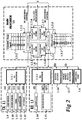
Fig 2 illustrates a primary radio transceiver of the system shown inFig 1 and includes a diagrammatic representation of a procedure whereby complete or partial change-over to a reserve unit is performed at appropriate times. - Referring firstly to
Fig 1 there are shown two identicalsimplex radio transceivers transceiver 1 is assumed to be initially set up to be the primary unit whilst thetransceiver 2 is initially a backup unit. Identical components associated with respective transceivers are denoted on the drawing with corresponding reference numerals. - The
primary transceiver 1 comprises a transmitter 1.1 having an associated antenna 1.2; a receiver 1.3 having an associated antenna 1.4; a main processor 1.5; interface circuitry 1.6 which converts digital signals to analogue form (and vice versa); and a switching facility 1.7 included as part of the circuitry 1.6. The components 1.1, 1.3, 1.5 and 1.6 are all connected by a bus 1.8. - Under the control of the processor 1.5, the switch 1.7 switches signals from an operator on line OL1 either to transmitter 1.1 or to
line 3. It also switches signals selectively from receiver 1.3 orline 4 onto the line OL1 and thence to the operator. - The
secondary transceiver 2 is identical totransceiver 1, the only difference being that software loaded into the processor 1.5 during an initial setup procedure instructs theunit 1 to behave initially as the primary transceiver and theunit 2 as the backup or reserve transceiver. - Referring now to
Fig 2 , the transmitter 1.1 contains a processor 1.1.1 which receives signals (a) to (e) as follows. The transceivers are connected by adata link 5. - Signal (a) is derived from a temperature sensor 1.9 and indicates that the temperature of the processor 1.1.1 is below a threshold level which might typically be about 90 degrees centigrade.
- Signal (b) is derived from a power measurement device 1.10 and indicates that the output power to the antenna 1.2 is either above a lower threshold level when the transmitter is in use but without modulation, or above a higher threshold level when the transmitter is in use with modulation. A typical lower threshold level might be 5 watts and a typical upper threshold might be 50 watts.
- Signal (c) is derived from a device 1.11 which calculates the voltage standing wave ratio on the output line to the antenna 1.2, and indicates that this is below a threshold value, signifying that power fed to the antenna is not being reflected back and that the antenna is therefore functioning correctly.
- Signal (d) is derived from a frequency synthesiser 1.12 within the transmitter and indicates that this has locked onto a preset desired frequency.
- Signal (e) is derived from a counter 1.13 which counts the number of PTT (press to talk) events since the last change-over operation. A signal (e) is produced so long as this count is below a preset maximum, eg four. After a changeover operation the counter is reset to zero.
- The receiver contains a processor 1.3.1 which is arranged to receive signals (f), (g1) and (g2) as follows.
- Signal (f) is obtained from a frequency synthesiser 1.14 and is equivalent to signal (d) of the transmitter.
- Signal (g1) is derived from a squelch status detector 1.15 indicating that the receiver is working and detecting a good signal.
- Signal (g2) is a squelch status signal indicating that the receiver is working but not detecting a good signal.
- Signal (h) is derived from a facility, indicated schematically at 1.16, within the main processor 1.5. It indicates that the transceiver is not currently in maintenance mode: i.e. maintenance equipment has not been connected to the port MP1 (
Fig 1 ) and registered by the main processor 1.5 as being in a status ready for downloading software. - Signal (i) is derived from a power supply status detector 1.17. It indicates that a power supply (not shown) is working and that the radio is switched on.
- All of the signals (a) to (i) are multiplexed onto the data bus 1.8 so that they can be utilised by the main processor 1.5. In addition to receiving the signals (a) to (i) from within the
unit 1, the main processor ofunit 1 also receives corresponding signals from thereserve unit 2 via adata link 5 which, in this particular embodiment is a cable. - The main processor 1.5 is programmed to perform the processes illustrated in
Fig 2 and which will now be described. It also has an associated memory in which look-up tables 1.5.1 and 1.5.2 are stored. These tables contain a score associated with each of the signals (a) to (i) as shown on the drawing. - At 1.5.3 the processor calculates the appropriate total score for the signals (a), (b), (c), (d), (e) and (h) from the main transceiver. A similar total is calculated at 1.5.4 using information from the backup transceiver accessed via
cable 5. The totals are compared at 1.5.5. - If the score for the backup unit is greater than for the main unit, a signal is applied to the data bus 1.8 instructing the processor 1.1.1 to shut down the
transmitter of the main unit. This signal also instructs the switching unit 1.6 to divert signals received from an operator on line OL1 (Fig 1 ) ontoline 3 from whence these signals for transmission are fed to the transmitter of the reserve unit. At the same time a signal is applied on thelink 5 instructing the transmitter of the reserve unit to switch on. - At 1.5.6 the processor calculates the total score for the signals (a), (b), (c), (d), (f), (g1) (g2), (h), and (i) from the main transceiver; and a similar total is calculated at 1.5.7 using information from the backup transceiver accessed via
cable 5. The totals are compared at 1.5.9. - If the score for the backup unit is greater than for the main unit, a signal is applied to the data bus 1.8 instructing the processor 1.3.1 to shut down the receiver of the main unit. This signal also instructs the switching unit 1.6 to cause signals received by the receiver 2.3 of the reserve unit and available on
line 4, to be switched onto the line OL1 in place of the signals received at 1.3. At the same time a signal is applied on thelink 5 instructing the receiver of the reserve unit to be switched on. - The scoring system as set out on
Fig 2 has the following desirable effects. - Firstly, each time that the operator presses his PTT (press to talk) button, the count at 1.1.3 is advanced. After four operations (this is just an example, any number could be chosen) the score calculated at 1.5.3 loses a value of 4 making it almost inevitable that a changeover will take place. This ensures that both transmitters are regularly used so that a malfunction of either of them will become apparent soon after it has arisen.
- Because the system selects the transmitter or receiver with the highest vote, one will be selected (the best one) even if there is a fault in both of them. Thus the system will try to operate even in the worst conditions.
- It is possible to perform maintenance operations on any one unit eg to update software or firmware, to add or change a physical module or to change settings without disconnecting the unit from the system or removal of it from its cabinet. This is achieved because commencement of the maintenance operation causes removal the signal (h) and therefore of its associated score of 2.
- It will be appreciated that the illustrated embodiment of the invention has been described only by way of example and that many variations are possible within the scope of the accompanying Claims. However it is believed that a radio system constructed on principles similar to those illustrated will be of considerable benefit to the safety of air traffic control radio systems because of the elimination of a separate change-over unit and of the risk that any such unit might itself be subject to failure.
Claims (3)
- An electronic system comprising two or more units (1, 2), characterised in that each unit includes at least a first transmitter component (1.1; 2.1) and a second receiver component (1.3; 2.3), which are adapted to exchange signals with an operator line (OL1), wherein each unit (1, 2) has at least one fault sensor (1.9, 1.10, 1.11, 1.12, 1.14, 1.15) effective to detect a fault in a component (1.1, 1.3; 2.1, 2.3) of that unit and an associated processor (1.5; 2.5) which is programmed and arranged to detect the fault condition and to trigger a substitution in response to such detection, wherein a first unit is arranged to behave as a primary unit (1) and a second unit is arranged to behave as a backup unit (2), and the processor (1.5) of the primary unit (1) is arranged to control a switching facility (1.7) included in the primary unit (1) so as to only switch signals from the operator line (OL1) to a transmitter (2.1) of the backup unit (2) if a fault is detected in a transmitter (1.1) of the primary unit (1), or only selectively switch to the operator line (OL1) signals from a receiver (2.3) of the backup unit (2) if a fault is detected in a receiver (1.3) of the primary unit (1), so that after switch the transmitter (1.1; 2.1) of one unit and the receiver (2.3; 1.3) of the other unit are operational.
- A system according to Claim 1 characterised in that the units (1, 2) are radio units for Air Traffic Control communications.
- A system according to Claim 2 further characterised in that the processor (1.5, 2.5) also serves to process signals being received or transmitted.
Priority Applications (5)
| Application Number | Priority Date | Filing Date | Title |
|---|---|---|---|
| EP17157177.1A EP3203638B1 (en) | 2004-12-24 | 2005-12-22 | Radio system with redundancy |
| DK17157177.1T DK3203638T3 (en) | 2004-12-24 | 2005-12-22 | RADIO SYSTEM WITH REDUNDANCE |
| PL17157177T PL3203638T3 (en) | 2004-12-24 | 2005-12-22 | Radio system with redundancy |
| PL05112815T PL1675272T3 (en) | 2004-12-24 | 2005-12-22 | Radio system with redundancy |
| CY20201100064T CY1122719T1 (en) | 2004-12-24 | 2020-01-23 | RADIO SYSTEM WITH REDUNDANCY |
Applications Claiming Priority (1)
| Application Number | Priority Date | Filing Date | Title |
|---|---|---|---|
| GB0428258A GB2421661A (en) | 2004-12-24 | 2004-12-24 | Self-diagnosis of faults in radio system with redundancy units |
Related Child Applications (2)
| Application Number | Title | Priority Date | Filing Date |
|---|---|---|---|
| EP17157177.1A Division EP3203638B1 (en) | 2004-12-24 | 2005-12-22 | Radio system with redundancy |
| EP17157177.1A Division-Into EP3203638B1 (en) | 2004-12-24 | 2005-12-22 | Radio system with redundancy |
Publications (2)
| Publication Number | Publication Date |
|---|---|
| EP1675272A1 EP1675272A1 (en) | 2006-06-28 |
| EP1675272B1 true EP1675272B1 (en) | 2017-04-12 |
Family
ID=34113185
Family Applications (2)
| Application Number | Title | Priority Date | Filing Date |
|---|---|---|---|
| EP05112815.5A Active EP1675272B1 (en) | 2004-12-24 | 2005-12-22 | Radio system with redundancy |
| EP17157177.1A Active EP3203638B1 (en) | 2004-12-24 | 2005-12-22 | Radio system with redundancy |
Family Applications After (1)
| Application Number | Title | Priority Date | Filing Date |
|---|---|---|---|
| EP17157177.1A Active EP3203638B1 (en) | 2004-12-24 | 2005-12-22 | Radio system with redundancy |
Country Status (9)
| Country | Link |
|---|---|
| EP (2) | EP1675272B1 (en) |
| CY (1) | CY1122719T1 (en) |
| DK (2) | DK3203638T3 (en) |
| ES (2) | ES2773517T3 (en) |
| GB (1) | GB2421661A (en) |
| HU (2) | HUE047691T2 (en) |
| LT (2) | LT3203638T (en) |
| PL (2) | PL1675272T3 (en) |
| PT (2) | PT3203638T (en) |
Families Citing this family (3)
| Publication number | Priority date | Publication date | Assignee | Title |
|---|---|---|---|---|
| CN101635646B (en) | 2009-06-24 | 2012-11-28 | 中兴通讯股份有限公司 | Method and system for switching main/standby board cards |
| DE102014203095A1 (en) * | 2014-02-20 | 2015-08-20 | Rohde & Schwarz Gmbh & Co. Kg | Radio system and method with time parameter evaluation |
| CN114280383B (en) * | 2021-12-28 | 2023-02-03 | 中国科学院空天信息创新研究院 | Health detection device and health detection method for large ground station antenna |
Family Cites Families (13)
| Publication number | Priority date | Publication date | Assignee | Title |
|---|---|---|---|---|
| GB2140583B (en) * | 1983-05-10 | 1986-05-08 | Dowty & Smiths Ind Controls | Engine control systems |
| JPS60259026A (en) * | 1984-06-05 | 1985-12-21 | Nec Corp | Automatic switching method in n:1 active spare equipment |
| JPH01279331A (en) * | 1988-04-30 | 1989-11-09 | Sharp Corp | Master action switching method for system consisting of two sheets of substrate containing cpu |
| JPH03232397A (en) * | 1990-02-08 | 1991-10-16 | Toshiba Corp | Backup switching system |
| US5940754A (en) * | 1992-06-17 | 1999-08-17 | Gte Laboratories Incorporated | Method of fault identification for multiplexed devices |
| FI109737B (en) * | 1993-08-25 | 2002-09-30 | Nokia Corp | Method and system for controlling the fuse of the recipients' frequency-frequency central channels in a digital transmission device |
| JP3770929B2 (en) * | 1994-11-09 | 2006-04-26 | 富士通株式会社 | Mobile communication system and radio base station |
| JP3189888B2 (en) * | 1997-12-12 | 2001-07-16 | 日本電気株式会社 | Early detection method and system for transceiver failure of wireless base station |
| DE19814096B4 (en) * | 1998-03-30 | 2007-07-19 | Abb Patent Gmbh | Method for switching over redundantly connected, similar modules |
| US6687217B1 (en) * | 1999-05-04 | 2004-02-03 | Carriercomm, Inc. | Method of and system for one plus one protection for radio equipment |
| JP3487830B2 (en) * | 2001-02-26 | 2004-01-19 | 埼玉日本電気株式会社 | Base station equipment |
| US7085225B2 (en) * | 2001-09-27 | 2006-08-01 | Alcatel Canada Inc. | System and method for providing detection of faults and switching of fabrics in a redundant-architecture communication system |
| JP3699049B2 (en) * | 2002-01-28 | 2005-09-28 | 日本電気通信システム株式会社 | Duplex transmission equipment |
-
2004
- 2004-12-24 GB GB0428258A patent/GB2421661A/en not_active Withdrawn
-
2005
- 2005-12-22 EP EP05112815.5A patent/EP1675272B1/en active Active
- 2005-12-22 PT PT171571771T patent/PT3203638T/en unknown
- 2005-12-22 PL PL05112815T patent/PL1675272T3/en unknown
- 2005-12-22 ES ES17157177T patent/ES2773517T3/en active Active
- 2005-12-22 ES ES05112815.5T patent/ES2632630T3/en active Active
- 2005-12-22 HU HUE17157177A patent/HUE047691T2/en unknown
- 2005-12-22 EP EP17157177.1A patent/EP3203638B1/en active Active
- 2005-12-22 DK DK17157177.1T patent/DK3203638T3/en active
- 2005-12-22 PL PL17157177T patent/PL3203638T3/en unknown
- 2005-12-22 PT PT51128155T patent/PT1675272T/en unknown
- 2005-12-22 LT LTEP17157177.1T patent/LT3203638T/en unknown
- 2005-12-22 LT LTEP05112815.5T patent/LT1675272T/en unknown
- 2005-12-22 HU HUE05112815A patent/HUE033086T2/en unknown
- 2005-12-22 DK DK05112815.5T patent/DK1675272T3/en active
-
2020
- 2020-01-23 CY CY20201100064T patent/CY1122719T1/en unknown
Non-Patent Citations (1)
| Title |
|---|
| None * |
Also Published As
| Publication number | Publication date |
|---|---|
| DK3203638T3 (en) | 2020-02-03 |
| ES2632630T3 (en) | 2017-09-14 |
| EP1675272A1 (en) | 2006-06-28 |
| PL1675272T3 (en) | 2017-10-31 |
| DK1675272T3 (en) | 2017-06-26 |
| EP3203638A1 (en) | 2017-08-09 |
| LT3203638T (en) | 2020-03-25 |
| ES2773517T3 (en) | 2020-07-13 |
| LT1675272T (en) | 2017-09-25 |
| CY1122719T1 (en) | 2021-03-12 |
| GB2421661A (en) | 2006-06-28 |
| PT1675272T (en) | 2017-06-16 |
| PT3203638T (en) | 2020-02-19 |
| GB0428258D0 (en) | 2005-01-26 |
| PL3203638T3 (en) | 2020-06-29 |
| EP3203638B1 (en) | 2019-11-20 |
| HUE033086T2 (en) | 2017-11-28 |
| HUE047691T2 (en) | 2020-05-28 |
Similar Documents
| Publication | Publication Date | Title |
|---|---|---|
| US6687217B1 (en) | Method of and system for one plus one protection for radio equipment | |
| CN106912069B (en) | Distributed antenna system remote terminal and uplink signal link detection method and device thereof | |
| US5408462A (en) | Protection switching apparatus and method | |
| US4700348A (en) | Hot standby communications system | |
| US7738842B2 (en) | Apparatus for protecting receiver circuit in time division duplexing wireless communication system | |
| US10790904B2 (en) | Redundant backup near-end machine, far-end machine and system thereof for digital optical fiber repeater | |
| US7782765B2 (en) | Distributed protection switching architecture for point-to-point microwave radio systems | |
| CN106330346B (en) | Remote radio unit and test method thereof | |
| US8304930B2 (en) | Fieldbus system with shared redundancy system | |
| EP3698484A1 (en) | Redundant wireless communication systems and methods to ensure radio service quality under abnormal conditions | |
| EP1675272B1 (en) | Radio system with redundancy | |
| US20030023892A1 (en) | Peer-to-peer redundancy control scheme with override feature | |
| CN103023554B (en) | Switch matrix device and remote sensing satellite data receiving system comprising same | |
| CN107005860B (en) | Signal backup system and method for active DAS system near-end machine | |
| US7043236B2 (en) | RF detection and switching system and method | |
| KR101407271B1 (en) | Duplex network system | |
| JP2012114552A (en) | Radio system | |
| KR19990055697A (en) | Redundant device and control method of beacon receiver | |
| JPH02166931A (en) | Alarm signal selection circuit | |
| JPH0722989A (en) | Hot standby transmission/reception system | |
| CN109274383A (en) | A kind of radio frequency switching device | |
| JPH03242032A (en) | Radio communication equipment | |
| JPH01115225A (en) | Antenna automatic tuning circuit | |
| JPH06284059A (en) | Automatic switching system for satellite communication line | |
| Cooney et al. | TH‐3 Medium‐Haul Application: Protection Switching |
Legal Events
| Date | Code | Title | Description |
|---|---|---|---|
| PUAI | Public reference made under article 153(3) epc to a published international application that has entered the european phase |
Free format text: ORIGINAL CODE: 0009012 |
|
| AK | Designated contracting states |
Kind code of ref document: A1 Designated state(s): AT BE BG CH CY CZ DE DK EE ES FI FR GB GR HU IE IS IT LI LT LU LV MC NL PL PT RO SE SI SK TR |
|
| AX | Request for extension of the european patent |
Extension state: AL BA HR MK YU |
|
| 17P | Request for examination filed |
Effective date: 20061227 |
|
| 17Q | First examination report despatched |
Effective date: 20070201 |
|
| AKX | Designation fees paid |
Designated state(s): AT BE BG CH CY CZ DE DK EE ES FI FR GB GR HU IE IS IT LI LT LU LV MC NL PL PT RO SE SI SK TR |
|
| GRAP | Despatch of communication of intention to grant a patent |
Free format text: ORIGINAL CODE: EPIDOSNIGR1 |
|
| INTG | Intention to grant announced |
Effective date: 20160708 |
|
| RIN1 | Information on inventor provided before grant (corrected) |
Inventor name: FANTAPPIE, PIERLUIGI |
|
| GRAS | Grant fee paid |
Free format text: ORIGINAL CODE: EPIDOSNIGR3 |
|
| RIN1 | Information on inventor provided before grant (corrected) |
Inventor name: FANTAPPIE, PIERLUIGI |
|
| RIN1 | Information on inventor provided before grant (corrected) |
Inventor name: FANTAPPIE, PIERLUIGI |
|
| GRAA | (expected) grant |
Free format text: ORIGINAL CODE: 0009210 |
|
| RAP1 | Party data changed (applicant data changed or rights of an application transferred) |
Owner name: LEONARDO S.P.A. |
|
| AK | Designated contracting states |
Kind code of ref document: B1 Designated state(s): AT BE BG CH CY CZ DE DK EE ES FI FR GB GR HU IE IS IT LI LT LU LV MC NL PL PT RO SE SI SK TR |
|
| REG | Reference to a national code |
Ref country code: GB Ref legal event code: FG4D |
|
| REG | Reference to a national code |
Ref country code: CH Ref legal event code: EP |
|
| REG | Reference to a national code |
Ref country code: IE Ref legal event code: FG4D |
|
| REG | Reference to a national code |
Ref country code: AT Ref legal event code: REF Ref document number: 884800 Country of ref document: AT Kind code of ref document: T Effective date: 20170515 |
|
| REG | Reference to a national code |
Ref country code: DE Ref legal event code: R096 Ref document number: 602005051715 Country of ref document: DE |
|
| REG | Reference to a national code |
Ref country code: RO Ref legal event code: EPE |
|
| REG | Reference to a national code |
Ref country code: SE Ref legal event code: TRGR |
|
| REG | Reference to a national code |
Ref country code: PT Ref legal event code: SC4A Ref document number: 1675272 Country of ref document: PT Date of ref document: 20170616 Kind code of ref document: T Free format text: AVAILABILITY OF NATIONAL TRANSLATION Effective date: 20170605 |
|
| REG | Reference to a national code |
Ref country code: NL Ref legal event code: FP |
|
| REG | Reference to a national code |
Ref country code: DK Ref legal event code: T3 Effective date: 20170621 |
|
| REG | Reference to a national code |
Ref country code: ES Ref legal event code: FG2A Ref document number: 2632630 Country of ref document: ES Kind code of ref document: T3 Effective date: 20170914 |
|
| REG | Reference to a national code |
Ref country code: EE Ref legal event code: FG4A Ref document number: E014076 Country of ref document: EE Effective date: 20170609 |
|
| REG | Reference to a national code |
Ref country code: SK Ref legal event code: T3 Ref document number: E 24430 Country of ref document: SK |
|
| REG | Reference to a national code |
Ref country code: GR Ref legal event code: EP Ref document number: 20170401813 Country of ref document: GR Effective date: 20171122 |
|
| REG | Reference to a national code |
Ref country code: HU Ref legal event code: AG4A Ref document number: E033086 Country of ref document: HU |
|
| REG | Reference to a national code |
Ref country code: FR Ref legal event code: PLFP Year of fee payment: 13 |
|
| REG | Reference to a national code |
Ref country code: DE Ref legal event code: R097 Ref document number: 602005051715 Country of ref document: DE |
|
| PLBE | No opposition filed within time limit |
Free format text: ORIGINAL CODE: 0009261 |
|
| STAA | Information on the status of an ep patent application or granted ep patent |
Free format text: STATUS: NO OPPOSITION FILED WITHIN TIME LIMIT |
|
| 26N | No opposition filed |
Effective date: 20180115 |
|
| PG25 | Lapsed in a contracting state [announced via postgrant information from national office to epo] |
Ref country code: SI Free format text: LAPSE BECAUSE OF FAILURE TO SUBMIT A TRANSLATION OF THE DESCRIPTION OR TO PAY THE FEE WITHIN THE PRESCRIBED TIME-LIMIT Effective date: 20170412 |
|
| PG25 | Lapsed in a contracting state [announced via postgrant information from national office to epo] |
Ref country code: MC Free format text: LAPSE BECAUSE OF FAILURE TO SUBMIT A TRANSLATION OF THE DESCRIPTION OR TO PAY THE FEE WITHIN THE PRESCRIBED TIME-LIMIT Effective date: 20170412 |
|
| PG25 | Lapsed in a contracting state [announced via postgrant information from national office to epo] |
Ref country code: CY Free format text: LAPSE BECAUSE OF NON-PAYMENT OF DUE FEES Effective date: 20170412 |
|
| REG | Reference to a national code |
Ref country code: AT Ref legal event code: UEP Ref document number: 884800 Country of ref document: AT Kind code of ref document: T Effective date: 20170412 |
|
| REG | Reference to a national code |
Ref country code: EE Ref legal event code: HC1A Ref document number: E014076 Country of ref document: EE |
|
| PGFP | Annual fee paid to national office [announced via postgrant information from national office to epo] |
Ref country code: SK Payment date: 20221205 Year of fee payment: 18 Ref country code: SE Payment date: 20221227 Year of fee payment: 18 Ref country code: RO Payment date: 20221207 Year of fee payment: 18 Ref country code: NL Payment date: 20221226 Year of fee payment: 18 Ref country code: LV Payment date: 20221207 Year of fee payment: 18 Ref country code: LU Payment date: 20221227 Year of fee payment: 18 Ref country code: LT Payment date: 20221201 Year of fee payment: 18 Ref country code: IE Payment date: 20221227 Year of fee payment: 18 Ref country code: GB Payment date: 20221227 Year of fee payment: 18 Ref country code: FR Payment date: 20221227 Year of fee payment: 18 Ref country code: FI Payment date: 20221227 Year of fee payment: 18 Ref country code: EE Payment date: 20221202 Year of fee payment: 18 Ref country code: DK Payment date: 20221227 Year of fee payment: 18 Ref country code: CZ Payment date: 20221209 Year of fee payment: 18 Ref country code: BG Payment date: 20221212 Year of fee payment: 18 Ref country code: AT Payment date: 20221202 Year of fee payment: 18 |
|
| PGFP | Annual fee paid to national office [announced via postgrant information from national office to epo] |
Ref country code: PT Payment date: 20221215 Year of fee payment: 18 Ref country code: PL Payment date: 20221205 Year of fee payment: 18 Ref country code: HU Payment date: 20221207 Year of fee payment: 18 Ref country code: GR Payment date: 20221229 Year of fee payment: 18 Ref country code: BE Payment date: 20221227 Year of fee payment: 18 |
|
| PGFP | Annual fee paid to national office [announced via postgrant information from national office to epo] |
Ref country code: TR Payment date: 20221220 Year of fee payment: 18 Ref country code: ES Payment date: 20230102 Year of fee payment: 18 Ref country code: CH Payment date: 20230109 Year of fee payment: 18 |
|
| PGFP | Annual fee paid to national office [announced via postgrant information from national office to epo] |
Ref country code: IS Payment date: 20230115 Year of fee payment: 18 Ref country code: DE Payment date: 20221228 Year of fee payment: 18 |
|
| PGFP | Annual fee paid to national office [announced via postgrant information from national office to epo] |
Ref country code: IT Payment date: 20231220 Year of fee payment: 19 |