EP1675188A2 - Solarzellenmodul und sein Einbauverfahren - Google Patents
Solarzellenmodul und sein Einbauverfahren Download PDFInfo
- Publication number
- EP1675188A2 EP1675188A2 EP05028005A EP05028005A EP1675188A2 EP 1675188 A2 EP1675188 A2 EP 1675188A2 EP 05028005 A EP05028005 A EP 05028005A EP 05028005 A EP05028005 A EP 05028005A EP 1675188 A2 EP1675188 A2 EP 1675188A2
- Authority
- EP
- European Patent Office
- Prior art keywords
- solar cell
- cell module
- trenches
- module
- parallel
- Prior art date
- Legal status (The legal status is an assumption and is not a legal conclusion. Google has not performed a legal analysis and makes no representation as to the accuracy of the status listed.)
- Withdrawn
Links
- 238000000034 method Methods 0.000 title claims abstract description 12
- XLYOFNOQVPJJNP-UHFFFAOYSA-N water Substances O XLYOFNOQVPJJNP-UHFFFAOYSA-N 0.000 abstract description 26
- 238000011109 contamination Methods 0.000 abstract description 19
- 229920005989 resin Polymers 0.000 abstract description 7
- 239000011347 resin Substances 0.000 abstract description 7
- 210000004027 cell Anatomy 0.000 description 117
- 239000010410 layer Substances 0.000 description 21
- 239000002390 adhesive tape Substances 0.000 description 18
- 230000001012 protector Effects 0.000 description 14
- 238000007789 sealing Methods 0.000 description 12
- 230000000052 comparative effect Effects 0.000 description 11
- 239000000853 adhesive Substances 0.000 description 8
- 230000001070 adhesive effect Effects 0.000 description 8
- -1 polyethylene terephthalate Polymers 0.000 description 6
- 229910021417 amorphous silicon Inorganic materials 0.000 description 5
- 230000001771 impaired effect Effects 0.000 description 5
- 238000009434 installation Methods 0.000 description 5
- 238000003475 lamination Methods 0.000 description 5
- 229920000840 ethylene tetrafluoroethylene copolymer Polymers 0.000 description 4
- 239000000758 substrate Substances 0.000 description 4
- 229910000831 Steel Inorganic materials 0.000 description 3
- 230000035515 penetration Effects 0.000 description 3
- 229920001343 polytetrafluoroethylene Polymers 0.000 description 3
- 239000004810 polytetrafluoroethylene Substances 0.000 description 3
- 229920002620 polyvinyl fluoride Polymers 0.000 description 3
- 239000000565 sealant Substances 0.000 description 3
- 239000010959 steel Substances 0.000 description 3
- 238000006467 substitution reaction Methods 0.000 description 3
- 239000002033 PVDF binder Substances 0.000 description 2
- 229920002873 Polyethylenimine Polymers 0.000 description 2
- 239000004642 Polyimide Substances 0.000 description 2
- 239000004734 Polyphenylene sulfide Substances 0.000 description 2
- 239000012790 adhesive layer Substances 0.000 description 2
- 230000006866 deterioration Effects 0.000 description 2
- 239000005038 ethylene vinyl acetate Substances 0.000 description 2
- 239000004744 fabric Substances 0.000 description 2
- 239000003365 glass fiber Substances 0.000 description 2
- 238000007689 inspection Methods 0.000 description 2
- 238000009413 insulation Methods 0.000 description 2
- 238000010030 laminating Methods 0.000 description 2
- 239000000463 material Substances 0.000 description 2
- 229910021424 microcrystalline silicon Inorganic materials 0.000 description 2
- 229920009441 perflouroethylene propylene Polymers 0.000 description 2
- 229920011301 perfluoro alkoxyl alkane Polymers 0.000 description 2
- 229920003207 poly(ethylene-2,6-naphthalate) Polymers 0.000 description 2
- 229920001200 poly(ethylene-vinyl acetate) Polymers 0.000 description 2
- 229920002312 polyamide-imide Polymers 0.000 description 2
- 229920001707 polybutylene terephthalate Polymers 0.000 description 2
- 239000011112 polyethylene naphthalate Substances 0.000 description 2
- 229920000139 polyethylene terephthalate Polymers 0.000 description 2
- 239000005020 polyethylene terephthalate Substances 0.000 description 2
- 229920001721 polyimide Polymers 0.000 description 2
- 229920000069 polyphenylene sulfide Polymers 0.000 description 2
- 229920002981 polyvinylidene fluoride Polymers 0.000 description 2
- XOLBLPGZBRYERU-UHFFFAOYSA-N tin dioxide Chemical compound O=[Sn]=O XOLBLPGZBRYERU-UHFFFAOYSA-N 0.000 description 2
- BQCIDUSAKPWEOX-UHFFFAOYSA-N 1,1-Difluoroethene Chemical compound FC(F)=C BQCIDUSAKPWEOX-UHFFFAOYSA-N 0.000 description 1
- KSFOVUSSGSKXFI-GAQDCDSVSA-N CC1=C/2NC(\C=C3/N=C(/C=C4\N\C(=C/C5=N/C(=C\2)/C(C=C)=C5C)C(C=C)=C4C)C(C)=C3CCC(O)=O)=C1CCC(O)=O Chemical compound CC1=C/2NC(\C=C3/N=C(/C=C4\N\C(=C/C5=N/C(=C\2)/C(C=C)=C5C)C(C=C)=C4C)C(C)=C3CCC(O)=O)=C1CCC(O)=O KSFOVUSSGSKXFI-GAQDCDSVSA-N 0.000 description 1
- 239000004812 Fluorinated ethylene propylene Substances 0.000 description 1
- 229920000106 Liquid crystal polymer Polymers 0.000 description 1
- 239000004977 Liquid-crystal polymers (LCPs) Substances 0.000 description 1
- 229930040373 Paraformaldehyde Natural products 0.000 description 1
- 239000004813 Perfluoroalkoxy alkane Substances 0.000 description 1
- 239000004952 Polyamide Substances 0.000 description 1
- 239000004962 Polyamide-imide Substances 0.000 description 1
- 229910000577 Silicon-germanium Inorganic materials 0.000 description 1
- LEVVHYCKPQWKOP-UHFFFAOYSA-N [Si].[Ge] Chemical compound [Si].[Ge] LEVVHYCKPQWKOP-UHFFFAOYSA-N 0.000 description 1
- 239000003522 acrylic cement Substances 0.000 description 1
- 239000000654 additive Substances 0.000 description 1
- 229910052782 aluminium Inorganic materials 0.000 description 1
- XAGFODPZIPBFFR-UHFFFAOYSA-N aluminium Chemical compound [Al] XAGFODPZIPBFFR-UHFFFAOYSA-N 0.000 description 1
- 229920005549 butyl rubber Polymers 0.000 description 1
- 239000000470 constituent Substances 0.000 description 1
- 230000007797 corrosion Effects 0.000 description 1
- 238000005260 corrosion Methods 0.000 description 1
- 230000007547 defect Effects 0.000 description 1
- 230000001419 dependent effect Effects 0.000 description 1
- 210000003743 erythrocyte Anatomy 0.000 description 1
- 238000011156 evaluation Methods 0.000 description 1
- 239000011521 glass Substances 0.000 description 1
- 239000003292 glue Substances 0.000 description 1
- 230000007774 longterm Effects 0.000 description 1
- 229910052751 metal Inorganic materials 0.000 description 1
- 239000002184 metal Substances 0.000 description 1
- 239000005304 optical glass Substances 0.000 description 1
- 229920002866 paraformaldehyde Polymers 0.000 description 1
- 229920002647 polyamide Polymers 0.000 description 1
- 229920000515 polycarbonate Polymers 0.000 description 1
- 239000004417 polycarbonate Substances 0.000 description 1
- 229920001296 polysiloxane Polymers 0.000 description 1
- 229920000131 polyvinylidene Polymers 0.000 description 1
- 229950003776 protoporphyrin Drugs 0.000 description 1
- 229910001220 stainless steel Inorganic materials 0.000 description 1
- 239000010935 stainless steel Substances 0.000 description 1
- 239000012815 thermoplastic material Substances 0.000 description 1
Images


Classifications
-
- H—ELECTRICITY
- H01—ELECTRIC ELEMENTS
- H01L—SEMICONDUCTOR DEVICES NOT COVERED BY CLASS H10
- H01L31/00—Semiconductor devices sensitive to infrared radiation, light, electromagnetic radiation of shorter wavelength or corpuscular radiation and specially adapted either for the conversion of the energy of such radiation into electrical energy or for the control of electrical energy by such radiation; Processes or apparatus specially adapted for the manufacture or treatment thereof or of parts thereof; Details thereof
- H01L31/04—Semiconductor devices sensitive to infrared radiation, light, electromagnetic radiation of shorter wavelength or corpuscular radiation and specially adapted either for the conversion of the energy of such radiation into electrical energy or for the control of electrical energy by such radiation; Processes or apparatus specially adapted for the manufacture or treatment thereof or of parts thereof; Details thereof adapted as photovoltaic [PV] conversion devices
- H01L31/042—PV modules or arrays of single PV cells
- H01L31/048—Encapsulation of modules
-
- Y—GENERAL TAGGING OF NEW TECHNOLOGICAL DEVELOPMENTS; GENERAL TAGGING OF CROSS-SECTIONAL TECHNOLOGIES SPANNING OVER SEVERAL SECTIONS OF THE IPC; TECHNICAL SUBJECTS COVERED BY FORMER USPC CROSS-REFERENCE ART COLLECTIONS [XRACs] AND DIGESTS
- Y02—TECHNOLOGIES OR APPLICATIONS FOR MITIGATION OR ADAPTATION AGAINST CLIMATE CHANGE
- Y02E—REDUCTION OF GREENHOUSE GAS [GHG] EMISSIONS, RELATED TO ENERGY GENERATION, TRANSMISSION OR DISTRIBUTION
- Y02E10/00—Energy generation through renewable energy sources
- Y02E10/50—Photovoltaic [PV] energy
Definitions
- the present invention relates to a solar cell module including photoelectric converters and a surface covering layer made of a resin provided to cover the light incident side of the photoelectric converters.
- the present invention relates also to a method of installing the solar cell module.
- the surface of a solar cell module including photoelectric converters, whose light incident side is covered with a surface covering layer made of a resin, is often damaged by vibrations and impacts caused during a transport of the solar cell module for the physical distribution thereof.
- solar cell modules including photoelectric converters bonded to a steel plate or a roofing tile and covered only with a resin film without disposing any optical glass plate on the light-incident-side surface thereof is damaged easily. Damages can be caused by the impact of a falling object during the transport of the solar cell module, by the drop of a tool during the installation of the solar cell module, by the collision of a foothold stuff after the installation of the solar cell module, and by the collision of a falling object during the long term use of the solar cell module.
- the adhesive tape is bonded by means of its adhesive to the uneven surface of the solar cell module. Therefore, the adhesive tape sticks only to the top portions of the mountains of the uneven surface of the solar cell module, hardly sticking to the entire module surface.
- a solar cell module including photoelectric converters, whose light incident side is covered with a resin surface covering layer, and a method of installing the solar cell module which allow to improve the adhesiveness between the module surface and the bonding portion of a repairing stuff, preventing water and contamination from getting into the bonding portion, preventing the solar cell module properties from being impaired, preventing any ground fault from being caused by the water, and preventing the repairing stuff from peeling.
- the trenches For one set of solar cell modules, it is preferable to arrange the trenches approximately in parallel to the surface of the pertinent module and in parallel to the horizontal plane of the module. In other words, it is preferable to arrange multiple lines of trenches in the longitudinal direction thereof and multiple rows of trenches in perpendicular to the longitudinal direction thereof.
- trenches are formed in the light incident side surface of the surface covering layer covering the light incident side surface of the photoelectric converters of the solar cell module such that the trenches, which have a certain width in the longitudinal direction thereof or widths changing alternately in the longitudinal direction thereof, are extended for a certain length, and the module is mounted on a supporting structure such that the trenches are approximately parallel to the horizontal plane and parallel to each other. Therefore, when damages caused in the module surface are covered with an adhesive tape or the like to use the solar cell module again, water and contamination hardly flow in the longitudinal direction of the trenches and the water and the contamination are prevented from getting into the bonding portion of the repairing stuff in the longitudinal direction of the trenches, i.e. substantially in parallel to the horizontal plane, in the usual mode of installing the solar cell module, in which the solar cell module is mounted on the supporting structure at a certain tilt angle, at which the solar cell module is facing to the solar ray side.
- the water and the contamination are prevented from getting into the bonding portion of the repairing stuff from the direction tilting at a certain angle to the longitudinal direction of the parallel trenches by the top surfaces of the land portions between the trenches.
- the performance of the solar cell module is prevented from being impaired by the water and the contamination which have come in, a ground fault and such a trouble are prevented from causing through the water, adhesive force lowering is prevented from causing in the bonding portion of the repairing stuff, the repairing stuff is prevented from being peeled due to the adhesive force lowering, the performances of the solar cell module are stabilized, and the durability of the solar cell module after the repair thereof is improved.
- FIG. 1 is a perspective view of a solar cell module set including solar cell modules.
- FIG. 1 shows the mounted state of the solar cell modules according to the first embodiment of the invention.
- FIG. 1 a solar cell module set 1 including solar cell modules and a module supporting structure 30 are shown.
- Module supporting structure 30 is tilted relative to the horizontal plane at a tilt angel a.
- Plural solar cell modules namely three modules 1 a, 1b, and 1c in this embodiment, are arranged in the lateral direction on the tilted mounting plane 30a of module supporting structure 30.
- the reference numeral 1 designates a solar cell module set or solar cell modules collectively.
- Solar cell module set 1 may be mounted on the roof of a structure via module supporting structure 30 such that solar cell modules 1 a through 1c and roofing stuff such as roofing tiles are formed into a unit.
- solar cell module set 1 may be mounted via module supporting structure 30 mounted on a rack disposed on a structure.
- solar cell module set 1 may be stuck on a plane or curved wall surface.
- solar cell module set 1 is tilted preferably southward, as shown in FIG. 1, to receive as much sun light as possible, solar cell module set 1 may be arbitrarily orientated to the west, north or other direction depending on the shape and the tilt of the structure.
- trenches 16 having a certain length are provided to extend in an X-direction substantially in parallel to the horizontal plane and in parallel to each other.
- substantially in this context means preferably the trenches extend in parallel to each other and to the horizontal plane, but practically unavoidable deviations from this preferred optimum are tolerable.
- Each trench 16 may extend in the X-direction across substantially the whole module with multiple trenches arranged in parallel to each other as is shown in the solar cell modules 1a and 1b, or, multiple trenches 16 are arranged along a line in the X-direction and multiple rows of such trench lines are arranged in the Y-direction as shown for module 1c.
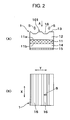
- FIG. 2(A) is a cross sectional view of the solar cell module according to the first embodiment of the invention.
- FIG. 2(B) is a top plan view of the solar cell module seen in the direction of the arrow A in FIG. 2(A).
- solar cell module 1 includes a photoelectric converter 11 in the core thereof, a light-incident-side sealing layer 12 and a protector sheet 13 laminated in this order on the light incident side of photoelectric converter 11. Sealing layer 12 and protector sheet 13 constitute a surface covering layer.
- a mounting side sealing layer 14 is laminated on a supporting base board 15.
- Supporting base board 15 serves as a mounting plane, via which solar cell module 1 is mounted on module supporting structure 30.
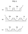
- the cross section of the trenches 16 according to the first embodiment may be trapezoidal as in FIG. 5(B), rectangular as in FIG. 5(A) or semicircular as in FIG. 5(C). It is preferably that the shape of the trenches 16 provides a wide contact area with an adhesive tape used for repairing to exhibit high adhesiveness. It is necessary to determine the shape of the trenches 16 considering the relation between the trench shape and the moldability of solar cell module 1.
- Preferable value ranges for the rectangular shape of the trenches according to Fig. 5(A) are 0.2 to 1 mm for the height (H), 0.3 to 1.2 mm for the bottom width (BW) of a trench and 0.1 to 0.4 mm for the interval (I) between adjacent trenches.
- the corresponding preferred value ranges are H: 0.05 to 0.2 mm, BW: 0.4 to 1.6 mm, 1: 0.2 to 1.2 mm and 0.2 to 0.6 mm for the projection of a trench's side wall onto the bottom plane.
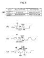
- the corresponding preferred value ranges are given by reference to those shown in Fig.
- the preferred range for the value 0.05 mm in Fig. 6(D) is 0.02 to 0.1 mm
- the preferred range for the value 0.6 mm in Fig. 6(D) is 0.3 to 1.2 mm
- the preferred range for the value 0.2 mm in Fig. 6(D) is 0.1 to 0.4 mm
- the preferred range for the value 0.1 mm in Fig. 6(D) is 0.05 to 0.2 mm.
- a-Si and a-SiGe for the tandem structure of photoelectric converter 11, a-C, a-SiC, microcrystalline silicon (hereinafter referred to as" ⁇ c-Si"), ⁇ c-SiGe, ⁇ c-SiC, and ⁇ c-Ge may be used.
- a-C, a-SiC, microcrystalline silicon hereinafter referred to as" ⁇ c-Si"
- ⁇ c-SiGe microcrystalline silicon
- ⁇ c-SiC microcrystalline silicon
- ⁇ c-SiC microcrystalline silicon
- ITO for the transparent electrode
- SnO 2 , ZnO and such a transparent electrically conductive film may be used.
- the surface covering layer on the light incident side of photoelectric converter 11 has a double-layered structure consisting of light-incident-side sealing layer 12 and protector sheet 13 according to the first embodiment of the invention, a triple-layered structure may be used, or a woven glass fiber cloth or a not-woven glass fiber cloth may be inserted.
- photoelectric converter 11 may be bonded or screwed directly to supporting base board 15 without using mounting side sealing layer 14.
- the solar cell module 1 according to the second embodiment includes trenches 16, each having narrow sections 16z of width B1 in the Y-direction, and wide sections 16y of width B2 in the Y-direction. B2 is greater than B1. Wide sections 16y and narrow sections 16z of each trench 16 are arranged alternately in the X-direction. The sequences of wide and narrow sections of adjacent trenches 16 are shifted relative to each other in the X-direction, so that a narrow section 16z of one trench opposes a wide section 16y of the neighboring trenches.
- the width B of trenches 16 may be changed continuously (wave-like) instead of stepwise as in Fig. 4.
- the other structures and functions are the same as those of the solar cell module according to the first embodiment.
- FIG. 7 is a perspective view of a comparative solar cell module set.
- FIG.8(A) is a cross sectional view of the comparative solar cell module of FIG. 7.
- FIG.8(B) is a top plan view of the solar cell module seen in the direction of the arrow B shown in FIG. 8(A). Note that in Fig. 8, the trench shape is exaggerated in the longitudinal direction, and 20a and 20b represent a film and an adhesive layer, respectively, of a transparent tape.
- a solar cell module set 1 of this comparative example differs from that of the first embodiment in that trenches 160 extend across solar cell modules 1a and 1b in the Y-direction rather than the X-direction. Apart from that the trenches 160 are shaped in the same manner as the trenches 16 according to the first or those of the second embodiment.
- trenches 160 in FIG. 7 extend perpendicular to the trenches 16 in FIG. 1.
- the comparative solar cell module set 1 is mounted on mounting plane 30a of module supporting member 30 such that the width direction of trenches 160 is in the X-direction approximately parallel to the horizontal plane 100, the longitudinal direction of the trenches 160 is in the Y-direction perpendicular to the X-direction, and trenches 160 are arranged parallel to each other in the X-direction.
- damage 21 is repaired by covering it with repairing stuff 20 like an adhesive tape as shown in FIG. 8(B). Since a gap is liable to be caused between repairing stuff 20 and the surface of solar cell module 1 in FIG. 8(A), water and contamination flow in the longitudinal direction of trenches 160 in FIG. 7, i.e. in the Y-direction, and, then, happen to get into the bonding portion of repairing stuff 20 forming the gap. Due to the penetration of the water and contamination, the adhesive force of repairing stuff 20 is impaired, it liable to peel from the surface of solar cell module 1.
- trenches 16 having a certain length and extended parallel to each other, are formed in the light incident side surface of a surface covering stuff (formed of light-incident-side sealing stuff 12 and protector sheet 13) covering the light incident side surface of photoelectric converter in solar cell module 1, and solar cell module 1 is mounted on module supporting stuff 30 in such an orientation that all the trenches 16 are extending in the X-direction substantially in parallel to the horizontal plane 100.
- a surface covering stuff formed of light-incident-side sealing stuff 12 and protector sheet 13
- trenches 16, each having narrow sections, the width thereof is B1, and wide sections, the width B2 thereof is wider than B1, arranged alternately in the longitudinal direction thereof, are formed in the light incident side surface of a surface covering stuff (formed of light-incident-side sealing stuff 12 and protector sheet 13) covering the light incident side surface of photoelectric converter in solar cell module 1, and solar cell module 1 is mounted on module supporting stuff 30 in such an orientation that all the trenches 16 are extending in the X-direction substantially in parallel to the horizontal plane 100.
- Trenches 16 are parallel to each other in the Y-direction perpendicular to the X-direction.
- solar cell module 1 having damages caused in the surface thereof and covered with repairing stuff 20 such an adhesive tape, is mounted on supporting structure 30 to use solar cell module 1 again in the usual mode of installation at a certain tilt angle ⁇ , at which the solar cell module is facing to the solar ray side.
- solar cell module 1 is used in the usual mode of installation, water and contamination hardly flow in the longitudinal direction of the trenches, i.e. the X-direction substantially parallel to the horizontal plane 100, and the water and the contamination are prevented from getting into from the Y-direction, i.e. the direction perpendicular to the longitudinal direction of trenches 16, by the top surfaces of the land portions between trenches 16.
- the tilt angle is preferably an angle at which the solar cell module is optimally exposed to the solar light.
- An example of the tilt angle is an angle corresponding to solar light falling perpendicularly or nearly perpendicularly on the solar cell module at a meridian passage in the northern hemisphere.
- the tilt angle may take various values depending on the condition of installation of the solar cell module or other factors.
- the properties of the solar cell module are prevented from being impaired by the water and contamination which have come in, a ground fault and like trouble are prevented from being caused by the water, the adhesive force is prevented lowering of repairing stuff 20 strongly bonded and prevent it from being peeled by the adhesive force lowering, the performances of solar cell module 1 are stabilized, and the durability of solar cell module 1 after the repair thereof is improved.
- FIG. 6(B) is a schematic cross sectional view of a rectangular trench describing the test conditions therefor.
- FIG. 6(C) is a schematic cross sectional view of a trapezoidal trench describing the test conditions therefor.
- FIG. 6(D) is a schematic cross sectional view of a semicircular trench describing the test conditions therefor.
- a solar cell module 1 was pasted to a steel plate of 0.8 mm thickness so that trenches 16 in the surface of the solar cell module 1 were aligned substantially parallel to the horizontal plane 100.
- Trenches 16 in this comparison were rectangular in cross section perpendicular to the longitudinal direction thereof as shown in FIG. 6(B).
- the trenches 16 were 0.5 mm in depth and 0.6 mm in width.
- the width of the land between trenches 16 was 0.2 mm..
- An ethylene-vinyl acetate copolymer film (hereinafter referred to as an "EVA film") of 0.7 mm thickness was used as the sealing layer 12 on the light-incident-side side.
- An ETFE film of 0.05 mm thickness was used as the protector sheet 13.
- the lamination conditions for the vacuum lamination process included deaeration at 120 °C for 2 min, curing at 155 °C for 20 min under a pressurized state, and release from the lamination process after lowering the temperature down to 80 °C.
- the damage reached the cell of module 1.
- the damaged module was dipped into water to evaluate the insulation performance thereof.
- the insulation resistance lowered down to 60 M ⁇ or lower.
- an adhesive tape was pasted onto the damaged solar cell module such that the distance between the damage and the edge of the adhesive tape was 20 mm.
- a force of 98 N was exerted to the adhesive tape using a roll of 100 mm in width to bond the adhesive tape to solar cell module 1 under pressure.
- Solar cell module 1 repaired as described above was installed on a plane, facing southward and tilted at 30 degrees, exposed for one year, and then evaluated after the final rain fall is over.
- the evaluation included external appearance inspection for confirming the rain water penetration into the gap between the adhesive tape and the module and inspection of the peeling states of the adhesive tape.
- the comparative tests confirm the superiority of solar cell module 1 according to each of the embodiments of the invention.
Landscapes
- Physics & Mathematics (AREA)
- Condensed Matter Physics & Semiconductors (AREA)
- Electromagnetism (AREA)
- General Physics & Mathematics (AREA)
- Engineering & Computer Science (AREA)
- Computer Hardware Design (AREA)
- Microelectronics & Electronic Packaging (AREA)
- Power Engineering (AREA)
- Photovoltaic Devices (AREA)
Applications Claiming Priority (1)
| Application Number | Priority Date | Filing Date | Title |
|---|---|---|---|
| JP2004370312A JP2006179624A (ja) | 2004-12-22 | 2004-12-22 | 太陽電池モジュール及びその設置方法 |
Publications (2)
| Publication Number | Publication Date |
|---|---|
| EP1675188A2 true EP1675188A2 (de) | 2006-06-28 |
| EP1675188A3 EP1675188A3 (de) | 2006-07-19 |
Family
ID=36215719
Family Applications (1)
| Application Number | Title | Priority Date | Filing Date |
|---|---|---|---|
| EP05028005A Withdrawn EP1675188A3 (de) | 2004-12-22 | 2005-12-21 | Solarzellenmodul und sein Einbauverfahren |
Country Status (3)
| Country | Link |
|---|---|
| US (1) | US7795527B2 (de) |
| EP (1) | EP1675188A3 (de) |
| JP (1) | JP2006179624A (de) |
Cited By (2)
| Publication number | Priority date | Publication date | Assignee | Title |
|---|---|---|---|---|
| CN102403410A (zh) * | 2011-11-25 | 2012-04-04 | 浙江帝龙光电材料有限公司 | 太阳能电池背板生产工艺 |
| EP2701204A3 (de) * | 2012-08-24 | 2018-01-10 | Industrial Technology Research Institute | Solarzelle und Solarzellenmodul |
Families Citing this family (4)
| Publication number | Priority date | Publication date | Assignee | Title |
|---|---|---|---|---|
| KR100974221B1 (ko) | 2008-04-17 | 2010-08-06 | 엘지전자 주식회사 | 레이저 어닐링을 이용한 태양전지의 선택적 에미터형성방법 및 이를 이용한 태양전지의 제조방법 |
| US10505062B2 (en) * | 2009-07-09 | 2019-12-10 | Faquir Chand Jain | High efficiency tandem solar cells and a method for fabricating same |
| TWM493154U (zh) * | 2013-08-29 | 2015-01-01 | Fuchi Textile Co Ltd | 可撓式光伏裝置 |
| JP6308901B2 (ja) * | 2014-07-15 | 2018-04-11 | 三菱電機株式会社 | 太陽電池モジュールおよび太陽電池モジュールの製造装置 |
Citations (7)
| Publication number | Priority date | Publication date | Assignee | Title |
|---|---|---|---|---|
| WO1993008605A1 (en) * | 1991-10-15 | 1993-04-29 | United Solar Systems Corporation | Photovoltaic device with increased light absorption and method for its manufacture |
| JPH08139347A (ja) * | 1994-11-04 | 1996-05-31 | Canon Inc | 太陽電池モジュール及びその製造方法 |
| JPH10270740A (ja) * | 1997-03-24 | 1998-10-09 | Figura Kk | 太陽電池の集光構造体 |
| JPH11307799A (ja) * | 1998-04-21 | 1999-11-05 | Canon Inc | 太陽電池モジュールの補修方法 |
| US20030098060A1 (en) * | 2001-10-29 | 2003-05-29 | Naoki Yoshimi | Solar battery sealing film and method of manufacturing solar battery panel using the same |
| JP2003188399A (ja) * | 2001-12-19 | 2003-07-04 | Fuji Electric Co Ltd | 太陽電池モジュール |
| JP2005086008A (ja) * | 2003-09-09 | 2005-03-31 | Fuji Electric Holdings Co Ltd | 太陽電池モジュールの補修方法 |
Family Cites Families (5)
| Publication number | Priority date | Publication date | Assignee | Title |
|---|---|---|---|---|
| JPH0379087A (ja) | 1989-08-22 | 1991-04-04 | Sharp Corp | 太陽光発電装置 |
| JPH0918030A (ja) | 1995-06-29 | 1997-01-17 | Fuji Electric Co Ltd | 薄膜太陽電池 |
| JP3872306B2 (ja) * | 2001-02-01 | 2007-01-24 | 信越半導体株式会社 | 太陽電池モジュール及び太陽電池モジュールの設置方法 |
| FR2823527B1 (fr) * | 2001-04-17 | 2003-12-12 | Jacques Lambey | Toiles photogeneratrices pour stores auvents et couvertures de piscine |
| US6670540B2 (en) * | 2001-10-10 | 2003-12-30 | Ecosol Solar Technologies Ltd. | Photovoltaic strip assembly |
-
2004
- 2004-12-22 JP JP2004370312A patent/JP2006179624A/ja active Pending
-
2005
- 2005-12-21 US US11/312,839 patent/US7795527B2/en not_active Expired - Fee Related
- 2005-12-21 EP EP05028005A patent/EP1675188A3/de not_active Withdrawn
Patent Citations (7)
| Publication number | Priority date | Publication date | Assignee | Title |
|---|---|---|---|---|
| WO1993008605A1 (en) * | 1991-10-15 | 1993-04-29 | United Solar Systems Corporation | Photovoltaic device with increased light absorption and method for its manufacture |
| JPH08139347A (ja) * | 1994-11-04 | 1996-05-31 | Canon Inc | 太陽電池モジュール及びその製造方法 |
| JPH10270740A (ja) * | 1997-03-24 | 1998-10-09 | Figura Kk | 太陽電池の集光構造体 |
| JPH11307799A (ja) * | 1998-04-21 | 1999-11-05 | Canon Inc | 太陽電池モジュールの補修方法 |
| US20030098060A1 (en) * | 2001-10-29 | 2003-05-29 | Naoki Yoshimi | Solar battery sealing film and method of manufacturing solar battery panel using the same |
| JP2003188399A (ja) * | 2001-12-19 | 2003-07-04 | Fuji Electric Co Ltd | 太陽電池モジュール |
| JP2005086008A (ja) * | 2003-09-09 | 2005-03-31 | Fuji Electric Holdings Co Ltd | 太陽電池モジュールの補修方法 |
Non-Patent Citations (5)
| Title |
|---|
| PATENT ABSTRACTS OF JAPAN vol. 1996, no. 09, 30 September 1996 (1996-09-30) -& JP 08 139347 A (CANON INC), 31 May 1996 (1996-05-31) * |
| PATENT ABSTRACTS OF JAPAN vol. 1999, no. 01, 29 January 1999 (1999-01-29) -& JP 10 270740 A (FIGURA KK), 9 October 1998 (1998-10-09) * |
| PATENT ABSTRACTS OF JAPAN vol. 2000, no. 02, 29 February 2000 (2000-02-29) -& JP 11 307799 A (CANON INC), 5 November 1999 (1999-11-05) * |
| PATENT ABSTRACTS OF JAPAN vol. 2003, no. 11, 5 November 2003 (2003-11-05) -& JP 2003 188399 A (FUJI ELECTRIC CO LTD), 4 July 2003 (2003-07-04) * |
| PATENT ABSTRACTS OF JAPAN vol. 2003, no. 12, 5 December 2003 (2003-12-05) -& JP 2005 086008 A (FUJI ELECTRIC HOLDINGS CO LTD), 31 March 2005 (2005-03-31) * |
Cited By (4)
| Publication number | Priority date | Publication date | Assignee | Title |
|---|---|---|---|---|
| CN102403410A (zh) * | 2011-11-25 | 2012-04-04 | 浙江帝龙光电材料有限公司 | 太阳能电池背板生产工艺 |
| CN102403410B (zh) * | 2011-11-25 | 2014-06-25 | 浙江帝龙光电材料有限公司 | 太阳能电池背板生产工艺 |
| EP2701204A3 (de) * | 2012-08-24 | 2018-01-10 | Industrial Technology Research Institute | Solarzelle und Solarzellenmodul |
| US9997646B2 (en) | 2012-08-24 | 2018-06-12 | Industrial Technology Research Institute | Solar cell, and solar cell module employing the same |
Also Published As
| Publication number | Publication date |
|---|---|
| EP1675188A3 (de) | 2006-07-19 |
| US20060151024A1 (en) | 2006-07-13 |
| JP2006179624A (ja) | 2006-07-06 |
| US7795527B2 (en) | 2010-09-14 |
Similar Documents
| Publication | Publication Date | Title |
|---|---|---|
| US6360497B1 (en) | Photovoltaic cell module tile | |
| US10563406B2 (en) | Roofing products having receptor zones and photovoltaic roofing elements and systems using them | |
| US9217584B2 (en) | Roofing products, photovoltaic roofing elements and systems using them | |
| US8733038B2 (en) | Roofing and siding products having receptor zones and photovoltaic roofing and siding elements and systems using them | |
| KR101188647B1 (ko) | 개량된 태양광 장치 및 방법 | |
| US6453629B1 (en) | Roofing tile having photovoltaic module to generate power | |
| EP1675188A2 (de) | Solarzellenmodul und sein Einbauverfahren | |
| US20110017278A1 (en) | Roofing products, photovoltaic roofing elements and systems using them | |
| US20080245405A1 (en) | Integrated Solar Cell Roofing System and Method of Manufacture | |
| WO2010061878A1 (ja) | 太陽電池モジュール | |
| US10511253B1 (en) | Shingle solar module with integrated backsheet | |
| US20190348553A1 (en) | Apparatus and method for photovoltaic module with tapered edge seal | |
| US9748894B2 (en) | Flexible building-integrated photovoltaic structure | |
| JP3940944B2 (ja) | 太陽電池モジュールの設置方法 | |
| KR20230142680A (ko) | 태양광 모듈 | |
| US20110108088A1 (en) | Photovoltaic structure and method of use | |
| US20190393371A1 (en) | Hot-melt laminated solar cladding strip | |
| JP2006318945A (ja) | 太陽電池モジュールの補修方法 | |
| JP2005086008A (ja) | 太陽電池モジュールの補修方法 | |
| WO2017037231A1 (en) | Solar panel and method of manufacturing such a solar panel | |
| US20240146234A1 (en) | Building integrated photovoltaic systems | |
| JP2006173339A (ja) | 太陽電池モジュール |
Legal Events
| Date | Code | Title | Description |
|---|---|---|---|
| PUAI | Public reference made under article 153(3) epc to a published international application that has entered the european phase |
Free format text: ORIGINAL CODE: 0009012 |
|
| PUAL | Search report despatched |
Free format text: ORIGINAL CODE: 0009013 |
|
| AK | Designated contracting states |
Kind code of ref document: A2 Designated state(s): AT BE BG CH CY CZ DE DK EE ES FI FR GB GR HU IE IS IT LI LT LU LV MC NL PL PT RO SE SI SK TR |
|
| AX | Request for extension of the european patent |
Extension state: AL BA HR MK YU |
|
| AK | Designated contracting states |
Kind code of ref document: A3 Designated state(s): AT BE BG CH CY CZ DE DK EE ES FI FR GB GR HU IE IS IT LI LT LU LV MC NL PL PT RO SE SI SK TR |
|
| AX | Request for extension of the european patent |
Extension state: AL BA HR MK YU |
|
| AKX | Designation fees paid | ||
| STAA | Information on the status of an ep patent application or granted ep patent |
Free format text: STATUS: THE APPLICATION IS DEEMED TO BE WITHDRAWN |
|
| 18D | Application deemed to be withdrawn |
Effective date: 20070120 |
|
| REG | Reference to a national code |
Ref country code: DE Ref legal event code: 8566 |