EP1674997A2 - Storage controller and method for storage control - Google Patents
Storage controller and method for storage control Download PDFInfo
- Publication number
- EP1674997A2 EP1674997A2 EP05251847A EP05251847A EP1674997A2 EP 1674997 A2 EP1674997 A2 EP 1674997A2 EP 05251847 A EP05251847 A EP 05251847A EP 05251847 A EP05251847 A EP 05251847A EP 1674997 A2 EP1674997 A2 EP 1674997A2
- Authority
- EP
- European Patent Office
- Prior art keywords
- data
- parity
- strips
- stripe
- memory devices
- Prior art date
- Legal status (The legal status is an assumption and is not a legal conclusion. Google has not performed a legal analysis and makes no representation as to the accuracy of the status listed.)
- Withdrawn
Links
Images



Classifications
-
- G—PHYSICS
- G06—COMPUTING OR CALCULATING; COUNTING
- G06F—ELECTRIC DIGITAL DATA PROCESSING
- G06F3/00—Input arrangements for transferring data to be processed into a form capable of being handled by the computer; Output arrangements for transferring data from processing unit to output unit, e.g. interface arrangements
- G06F3/06—Digital input from, or digital output to, record carriers, e.g. RAID, emulated record carriers or networked record carriers
-
- H—ELECTRICITY
- H04—ELECTRIC COMMUNICATION TECHNIQUE
- H04N—PICTORIAL COMMUNICATION, e.g. TELEVISION
- H04N21/00—Selective content distribution, e.g. interactive television or video on demand [VOD]
- H04N21/20—Servers specifically adapted for the distribution of content, e.g. VOD servers; Operations thereof
- H04N21/21—Server components or server architectures
-
- G—PHYSICS
- G06—COMPUTING OR CALCULATING; COUNTING
- G06F—ELECTRIC DIGITAL DATA PROCESSING
- G06F11/00—Error detection; Error correction; Monitoring
- G06F11/07—Responding to the occurrence of a fault, e.g. fault tolerance
- G06F11/08—Error detection or correction by redundancy in data representation, e.g. by using checking codes
- G06F11/10—Adding special bits or symbols to the coded information, e.g. parity check, casting out 9's or 11's
- G06F11/1076—Parity data used in redundant arrays of independent storages, e.g. in RAID systems
-
- G—PHYSICS
- G06—COMPUTING OR CALCULATING; COUNTING
- G06F—ELECTRIC DIGITAL DATA PROCESSING
- G06F3/00—Input arrangements for transferring data to be processed into a form capable of being handled by the computer; Output arrangements for transferring data from processing unit to output unit, e.g. interface arrangements
-
- G—PHYSICS
- G06—COMPUTING OR CALCULATING; COUNTING
- G06F—ELECTRIC DIGITAL DATA PROCESSING
- G06F3/00—Input arrangements for transferring data to be processed into a form capable of being handled by the computer; Output arrangements for transferring data from processing unit to output unit, e.g. interface arrangements
- G06F3/06—Digital input from, or digital output to, record carriers, e.g. RAID, emulated record carriers or networked record carriers
- G06F3/0601—Interfaces specially adapted for storage systems
- G06F3/0602—Interfaces specially adapted for storage systems specifically adapted to achieve a particular effect
- G06F3/061—Improving I/O performance
- G06F3/0613—Improving I/O performance in relation to throughput
-
- G—PHYSICS
- G06—COMPUTING OR CALCULATING; COUNTING
- G06F—ELECTRIC DIGITAL DATA PROCESSING
- G06F3/00—Input arrangements for transferring data to be processed into a form capable of being handled by the computer; Output arrangements for transferring data from processing unit to output unit, e.g. interface arrangements
- G06F3/06—Digital input from, or digital output to, record carriers, e.g. RAID, emulated record carriers or networked record carriers
- G06F3/0601—Interfaces specially adapted for storage systems
- G06F3/0628—Interfaces specially adapted for storage systems making use of a particular technique
- G06F3/0646—Horizontal data movement in storage systems, i.e. moving data in between storage devices or systems
- G06F3/065—Replication mechanisms
-
- G—PHYSICS
- G06—COMPUTING OR CALCULATING; COUNTING
- G06F—ELECTRIC DIGITAL DATA PROCESSING
- G06F3/00—Input arrangements for transferring data to be processed into a form capable of being handled by the computer; Output arrangements for transferring data from processing unit to output unit, e.g. interface arrangements
- G06F3/06—Digital input from, or digital output to, record carriers, e.g. RAID, emulated record carriers or networked record carriers
- G06F3/0601—Interfaces specially adapted for storage systems
- G06F3/0668—Interfaces specially adapted for storage systems adopting a particular infrastructure
- G06F3/0671—In-line storage system
- G06F3/0683—Plurality of storage devices
- G06F3/0689—Disk arrays, e.g. RAID, JBOD
-
- H—ELECTRICITY
- H04—ELECTRIC COMMUNICATION TECHNIQUE
- H04N—PICTORIAL COMMUNICATION, e.g. TELEVISION
- H04N21/00—Selective content distribution, e.g. interactive television or video on demand [VOD]
- H04N21/20—Servers specifically adapted for the distribution of content, e.g. VOD servers; Operations thereof
- H04N21/23—Processing of content or additional data; Elementary server operations; Server middleware
-
- G—PHYSICS
- G06—COMPUTING OR CALCULATING; COUNTING
- G06F—ELECTRIC DIGITAL DATA PROCESSING
- G06F2211/00—Indexing scheme relating to details of data-processing equipment not covered by groups G06F3/00 - G06F13/00
- G06F2211/10—Indexing scheme relating to G06F11/10
- G06F2211/1002—Indexing scheme relating to G06F11/1076
- G06F2211/1057—Parity-multiple bits-RAID6, i.e. RAID 6 implementations
-
- G—PHYSICS
- G11—INFORMATION STORAGE
- G11B—INFORMATION STORAGE BASED ON RELATIVE MOVEMENT BETWEEN RECORD CARRIER AND TRANSDUCER
- G11B2220/00—Record carriers by type
- G11B2220/40—Combinations of multiple record carriers
- G11B2220/41—Flat as opposed to hierarchical combination, e.g. library of tapes or discs, CD changer, or groups of record carriers that together store one title
- G11B2220/415—Redundant array of inexpensive disks [RAID] systems
Definitions
- the present invention relates to a storage controller which controls the distribution and storage of data and parities in a plurality of memory devices such as RAID (Redundant Array of Inexpensive Disks), and a method thereof.
- RAID Redundant Array of Inexpensive Disks
- RAID is a technology wherein a plurality of hard disks are combined and controlled as one redundant hard disk and is classified into seven levels, from RAID 0 to RAID 6, according to the methods for data allocation to disks and data redundancy. Out of these levels, in RAID 3 to Raid 6, redundancy is realized by storing parities, which have been created from data, independently of the data (for example, refer to Japanese Patent Laid-Open Publication No. 2000-259359).
- RAID 5 The mapping of RAID 5 is described first.
- performance enhancement is achieved by changing the disk which handles parities, fixed in RAID 4, every time stripes change in order to distribute the parities.
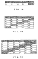
- the allocation of one stripe by RAID 5 mapping is as shown in Fig. 1A.
- an (N + 1) RAID configuration indicates a configuration wherein the number of disks, N, out of (N +1) disks, handle data strips and one disk handles the parity strips.
- one stripe comprises data D00 to D03 which are each allocated to four disks, Disk 0 to Disk 3, and parity P00 which is allocated to Disk 4.
- Data D00 to D03 are arranged and allocated in sequential order of the subscripts starting from D00.
- Disk 4 to which the parity is allocated, is not used for read requests for D00 to D03.
- a read request wherein data which span different stripes is read in sequential order of the subscripts may also be considered.
- it is effective to allocate data D04, which is the head of the next stripe, to Disk 4, to which Parity P00 had been allocated in the previous stripe and to which no access has been made. For example, if the positions of the head data in each stripe are each shifted with every stripe, the allocation of data and parities are as shown in Fig. 1B.
- RAID 6 is a RAID level which addresses the failure of a plurality of disks.
- RAID 6 is indicated by an (N + M) RAID configuration and holds the parity with each stripe, as in RAID 5. Since the M number of disks to which parities are allocated corresponds to the failure of a plurality of disks, it is two or more.
- Parity P which is equivalent to RAID 5, and parities Q, R, S, and the like, which differ from parity P, are generally used as these parities.
- the objective of the present invention is to perform mapping for improving the sequential read performance of a storage device such as RAID, which attains data redundancy by using two or more types of parities.
- the storage device comprises a determination device and a controlling device and realizes data redundancy by controlling the distribution and storage of stripes, comprising N number of data strips and M number of parity strips of a different type, to N + M number of memory devices.
- the determination device determines the storage destination memory device for the N number of data strips and the M number of parity strips comprised in each stripe, so as to avoid continuously storing the parity strips to the same memory device between two continuous stripes when N + M number of memory devices store a plurality of stripes.
- the controlling device controls the storage of the N number of data strips and two or more parity strips to each of the determined storage destination memory devices.
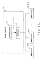
- Fig. 2A is a principle diagram of a storage controller according to the present invention.
- the storage controller 101 in Fig. 2A comprises a determination device 111 and a controller 112 and realizes data redundancy by controlling the distribution and storage of a stripe, comprising N number of data strips and M number of parity strips of a different type, to N + M number of memory devices, 102-1, 102-2, ----- 102-(N+M).
- the determination device 111 determines the storage destination memory devices for the N number of data strips and the M number of parity strips of different types, so as to avoid continuously storing the parity strips to the same memory device between two continuous stripes when the memory devices, 102-1, 102-2, ---- 102-(N + M), store a plurality of stripes.
- the controller 112 controls the storage of the N number of data strips and two or more parity strips to each of the determined storage destination memory devices.
- each memory device is equivalent to one or more magnetic disk device. If a plurality of stripes are stored, data and parities within one stripe are dispersed and stored to memory devices 102-1, 102-2, ---- 102- (N + M) so that the same memory does not continuously handle the same type or different types of parity strips between two consecutive stripes. Through this, the access frequency to the N + M number of memory devices is equalized when data which spans different stripes are sequentially read.
- the storage device 101 corresponds to, for example, the controller 211 in Fig. 2B, the host bus adaptor 1311 in Fig. 13, or the host device 1401 in Fig. 14, described later.
- the performance of sequential read is enhanced in the storage device wherein the stripe comprising N number of data strips and M number of parity strips of different types is distributed and stored in N + M number of memory devices.
- Fig. 2B shows a configuration example of the storage system in the embodiment.
- the storage system in Fig. 2B comprises a host device 201 and a RAID device 202.
- the RAID device 202 corresponds to the storage device which comprises the controller 211 and six disks, Disk 0 to Disk 5.
- Each disk comprises one or more magnetic disk devices, and the host device 201 regards all these disks as one memory device and performs Read/Write of the data.
- the number of disks connected to the controller 211 is not necessarily limited to six.
- the controller 211 comprises a processor 221, memory 222, and cache memory 223 and controls access to Disk 0 to Disk 5.
- the processor 221 controls access by executing the program stored in the memory 222.
- mappings in the present embodiment in the (N + M) RAID configuration are described next, in reference to Fig. 3 to Fig. 11.
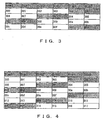
- the mapping is as shown in Fig. 3.
- the data and the parities are collectively allocated respectively, and the disk handling the same type of parity is shifted by M number of disks for every stripe. In this case, since the same disk never handles the parity in two consecutive stripes, the performance of the sequential read is enhanced.
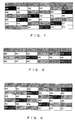
- both stripes wherein P and Q are arranged in order and stripe wherein Q and P are arranged in order are created and allocated so that all disks handle both P and Q. Then, the disks handling of P and Q is circulated every (N + M) /M stripes. Therefore, allocation is performed in an (N + M) stripe cycle.
- P and Q are not allocated consecutively, but are one or more disks apart.
- the two improvement ideas, above, are ideas for reducing the differences in load caused by Parity P and Parity Q in the RAID 6 not being equal parity strips and having differing roles.
- the improvement idea (2) is considered the more effective of the two.
- the role of the data strip may differ as do the roles of Parity P and Parity Q.
- RAID 6 which is called the RDP (Row-Diagonal Parity) system
- a diagonal parity Q is created by using data and the Parity P of RAID 5.
- the roles of each strip within one stripe are not equal. Specifically, in regards to one strip out of the data or P, the entire strip is used to create the diagonal parity Q. On the other hand, in the remaining data and Parity P strips, only a part thereof is used to create Q.
- the entire P strip used to create Q is determined to be assigned to one of the data strips, and not to the P strip.
- the head data strip within the stripe is a strip that uses all the data to create Q.
- the load is not equally distributed in the mappings in Fig. 3 and Fig. 4 because there are disks which handle the head data and disks which do not.
- the head data is allocated to Disk 0, Disk 2, and Disk 4, and the head data is not allocated to Disk 1, Disk 3, or Disk 5.
- the cyclic rearrangement of P and Q implemented in the mapping in Fig. 4, is implemented for the data strip as shown in Fig. 6, and the mapping order of the data and the parities to the arrayed M number of disks is circulated every (N + M)/M stripes.
- the allocations of the first three stripes, 601 to 603, are the same as in Fig. 4, and the head data, D00, D04 and D08, of each stripe are distributed to Disk 0, Disk 4 and Disk 2.
- This mapping is a variation of the improvement idea in (4), above. As shown in Fig. 7, although the allocation of the parities is the same as that in Fig. 3, the allocation of data differs. In this mapping, the location of the head data within the stripe is selected by shifting the location for every stripe, out of the M number of disks handling the parity in the immediately preceding stripe. However, since the 2nd data to M-th data may be allocated to the disk handling data also in the immediately preceding stripe, this is inferior in terms of sequential read performance to the improvement idea in (4).
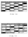
- Figs. 8, 9, 10, and 11 show the examples wherein the mappings in (1), (2), (3), and (4) are each applied to a (3 +3) RAID configuration.
- the controller 211 performs a mapping process, such as that explained above, according to the RAID configuration in order to perform a Read/Write Access of data or parities to the disk. Therefore, the mapping process performed by the controller 211 in the (N + M) RAID configuration is described in detail.
- mapping process using the afore-mentioned definitions of the variables is described next.
- the stripe number i and the strip number j are determined from the data address a according to the mapping method, and the disk number d of the access target is determined.
- d ( j + i ⁇ ( N + M ⁇ 1 ) ) % ( N + M )
- d ( j + ( i ⁇ N ) ) % ( N + M )
- ptop ( N + ( i ⁇ N ) ) % ( N + M ) d
- d p top + ( j ⁇ N + ( M ⁇ 1 ) ⁇ ( i / ( n + M ) / M ) ) % M
- d ( i ⁇ ( N + M ⁇ 1 ) + j / ( N / M ) ⁇ ( ( N + M ) / M + j % ( N / M ) ) % ( N + M )
- d ( i ⁇ ( N + M ⁇ 1 ) + ( j ⁇ N ) ⁇ ( ( N + M ) / M ) + ( N / M ) ) % ( N + M )
- the circulation of the M number of parities in the afore-mentioned second mapping is also applied to data, and the array of the M number of data is circulated by group as one group.
- the controller 211 performs Read/Write of the data or the parity, with the disk corresponding to the value of d obtained by the formulas, above, as the access target.
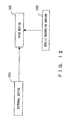
- Fig. 12 shows a method for providing the program and data that the processor 221 of the controller 221 uses for processing.
- Program and data stored in external device 1201, such as information processors, or mobile recording medium 1202 are loaded to the memory 222 of the RAID device 202.
- the external device 1201 generates a carrier signal which carries this program and data and transmits this signal to the RAID device 202 through an arbitrary transmission medium on a communication network.
- the mobile recording medium 1202 is an arbitrary computer-readable recording medium, such as a memory card, a flexible disk, an optical disk, or a magneto-optical disk.
- the processor 221 executes the program using this data and performs the necessary processing.
- Figs. 13 and 14 show other configuration examples of the storage system.
- Fig. 13 shows an example wherein a host bus adaptor mounted on the host device controls disk access.
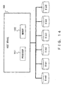
- Fig. 14 shows an example wherein software installed in the host device controls disk access. In either of the configurations, the necessary program and data are provided as in the RAID device 202.
- the storage system in Fig. 13 comprises a host device 1301 and Disk 0 to Disk 5.
- the host device 1301 comprises a host bus adaptor 1311.
- the host bus adaptor 1311 comprises a processor 1321, memory 1322, and cache memory 1323, and controls access to Disk 0 to Disk 5.
- the processor 1321 executes the program stored in the memory 1322 to perform the afore-mentioned mapping processing.
- the storage system in Fig. 14 comprises a host device 1401 and Disk 0 to Disk 5.
- the host device 1401 comprises a processor 1411 and memory 1412 and controls access to Disk 0 to Disk 5.
- the processor 1411 executes the program stored in the memory 1412 to perform the afore-mentioned mapping processing.
- magneto-optical disk device is used as a disk device in the afore-mentioned embodiments
- the present invention can be applied to a storage system which uses disk devices such as optical disk device, magneto-optical disk device, and other memory devices such as tape devices.
Landscapes
- Engineering & Computer Science (AREA)
- Theoretical Computer Science (AREA)
- Physics & Mathematics (AREA)
- General Engineering & Computer Science (AREA)
- General Physics & Mathematics (AREA)
- Human Computer Interaction (AREA)
- Multimedia (AREA)
- Signal Processing (AREA)
- Quality & Reliability (AREA)
- Techniques For Improving Reliability Of Storages (AREA)
- Detection And Correction Of Errors (AREA)
Abstract
Description
- The present invention relates to a storage controller which controls the distribution and storage of data and parities in a plurality of memory devices such as RAID (Redundant Array of Inexpensive Disks), and a method thereof.
- RAID is a technology wherein a plurality of hard disks are combined and controlled as one redundant hard disk and is classified into seven levels, from RAID 0 to RAID 6, according to the methods for data allocation to disks and data redundancy. Out of these levels, in RAID 3 to Raid 6, redundancy is realized by storing parities, which have been created from data, independently of the data (for example, refer to Japanese Patent Laid-Open Publication No. 2000-259359).
- The mapping of RAID 5 is described first. In RAID 5, performance enhancement is achieved by changing the disk which handles parities, fixed in RAID 4, every time stripes change in order to distribute the parities. For example, in the case of a (4 + 1) RAID configuration, the allocation of one stripe by RAID 5 mapping is as shown in Fig. 1A.
- Here, an (N + 1) RAID configuration indicates a configuration wherein the number of disks, N, out of (N +1) disks, handle data strips and one disk handles the parity strips. In the example in Fig. 1A, one stripe comprises data D00 to D03 which are each allocated to four disks, Disk 0 to Disk 3, and parity P00 which is allocated to Disk 4. Data D00 to D03 are arranged and allocated in sequential order of the subscripts starting from D00.
- A conventional read process for reading data stored as such does not require parity P00. Therefore, Disk 4, to which the parity is allocated, is not used for read requests for D00 to D03.
- If a plurality of stripes is stored in Disk 0 to Disk 4, a read request wherein data which span different stripes is read in sequential order of the subscripts may also be considered. When taking into consideration performance in a sequential read process such as this, it is effective to allocate data D04, which is the head of the next stripe, to Disk 4, to which Parity P00 had been allocated in the previous stripe and to which no access has been made. For example, if the positions of the head data in each stripe are each shifted with every stripe, the allocation of data and parities are as shown in Fig. 1B.
- The mappings of data and parities are generally performed in an (N+1)-stripe cycle, corresponding to the (N+1) RAID configuration. Since N = 4 here, it is a 5-stripe cycle.
- The mapping of RAID 6 is described next. RAID 6 is a RAID level which addresses the failure of a plurality of disks. RAID 6 is indicated by an (N + M) RAID configuration and holds the parity with each stripe, as in RAID 5. Since the M number of disks to which parities are allocated corresponds to the failure of a plurality of disks, it is two or more. Parity P, which is equivalent to RAID 5, and parities Q, R, S, and the like, which differ from parity P, are generally used as these parities.
- In the following explanation, in order to address the failure of two disks, the parity P and parity Q are used, with M = 2.
- If the mapping of RAID 5 shown in Fig. 1B is applied to the (4 + 2) RAID configuration in RAID 6, the allocation of data and parities are as shown in Fig. 1C. Generally, this is the allocation in the (N + M) stripe cycle, and all of the disks handle both parity P and parity Q.
- The mapping of a conventional RAID 6, described above, has the following problem.
- In the mapping of RAID 6 shown in Fig. 1C, the same disk handles parity P and parity Q in two consecutive stripes and does not handle data. This is not desirable from the viewpoint of sequential read performance.
- The objective of the present invention is to perform mapping for improving the sequential read performance of a storage device such as RAID, which attains data redundancy by using two or more types of parities.
- The storage device according to the present invention comprises a determination device and a controlling device and realizes data redundancy by controlling the distribution and storage of stripes, comprising N number of data strips and M number of parity strips of a different type, to N + M number of memory devices.
- The determination device determines the storage destination memory device for the N number of data strips and the M number of parity strips comprised in each stripe, so as to avoid continuously storing the parity strips to the same memory device between two continuous stripes when N + M number of memory devices store a plurality of stripes. The controlling device controls the storage of the N number of data strips and two or more parity strips to each of the determined storage destination memory devices.
-
- Fig. 1A is a diagram showing a stripe in RAID 5;
- Fig. 1B is a diagram showing a mapping in RAID 5;
- Fig. 1C is a diagram showing a mapping in RAID 6;
- Fig. 2A is the principle diagram of a storage controller according to the present invention;
- Fig. 2B is a diagram showing the configuration diagram of a first storage system;
- Fig. 3 is a diagram showing a first mapping when M =2;
- Fig. 4 is a diagram showing a second mapping when M =2;
- Fig. 5 is a diagram showing a third mapping when M =2;
- Fig. 6 is a diagram showing a fourth mapping when M =2;
- Fig. 7 is a diagram showing a fifth mapping when M =2;
- Fig. 8 is a diagram showing a first mapping when M = 3;
- Fig. 9 is a diagram showing a second mapping when M = 3;
- Fig. 10 is a diagram showing a third mapping when M = 3;
- Fig. 11 is a diagram showing a fourth mapping when M = 3;
- Fig. 12 is a diagram showing a method for providing a program and data;
- Fig. 13 is a configuration diagram showing a second storage system; and
- Fig. 14 is a configuration diagram showing a third storage system.
- The preferred embodiments for implementing the present invention are described in detail below, in reference to the diagrams.
- Fig. 2A is a principle diagram of a storage controller according to the present invention. The
storage controller 101 in Fig. 2A comprises adetermination device 111 and acontroller 112 and realizes data redundancy by controlling the distribution and storage of a stripe, comprising N number of data strips and M number of parity strips of a different type, to N + M number of memory devices, 102-1, 102-2, ----- 102-(N+M). - The
determination device 111 determines the storage destination memory devices for the N number of data strips and the M number of parity strips of different types, so as to avoid continuously storing the parity strips to the same memory device between two continuous stripes when the memory devices, 102-1, 102-2, ---- 102-(N + M), store a plurality of stripes. Thecontroller 112 controls the storage of the N number of data strips and two or more parity strips to each of the determined storage destination memory devices. - In an (N + M) RAID configuration, each memory device is equivalent to one or more magnetic disk device. If a plurality of stripes are stored, data and parities within one stripe are dispersed and stored to memory devices 102-1, 102-2, ---- 102- (N + M) so that the same memory does not continuously handle the same type or different types of parity strips between two consecutive stripes. Through this, the access frequency to the N + M number of memory devices is equalized when data which spans different stripes are sequentially read.
- The
storage device 101 corresponds to, for example, thecontroller 211 in Fig. 2B, thehost bus adaptor 1311 in Fig. 13, or thehost device 1401 in Fig. 14, described later. - According to the present invention, the performance of sequential read is enhanced in the storage device wherein the stripe comprising N number of data strips and M number of parity strips of different types is distributed and stored in N + M number of memory devices.
- Fig. 2B shows a configuration example of the storage system in the embodiment. The storage system in Fig. 2B comprises a
host device 201 and aRAID device 202. TheRAID device 202 corresponds to the storage device which comprises thecontroller 211 and six disks, Disk 0 to Disk 5. - Each disk comprises one or more magnetic disk devices, and the
host device 201 regards all these disks as one memory device and performs Read/Write of the data. The number of disks connected to thecontroller 211 is not necessarily limited to six. - The
controller 211 comprises aprocessor 221,memory 222, andcache memory 223 and controls access to Disk 0 to Disk 5. Theprocessor 221 controls access by executing the program stored in thememory 222. - Examples of mappings in the present embodiment in the (N + M) RAID configuration are described next, in reference to Fig. 3 to Fig. 11.
- If, taking the performance of sequential read into consideration, in the (4 + 2) RAID configuration shown in Fig. 1C, the allocation is shifted by two disks for every stripe, so that the parities are not continuous, the mapping is as shown in Fig. 3. In this mapping, the data and the parities are collectively allocated respectively, and the disk handling the same type of parity is shifted by M number of disks for every stripe. In this case, since the same disk never handles the parity in two consecutive stripes, the performance of the sequential read is enhanced.
- Generally, in the (N + M) RAID configuration, if the number of disks, (N + M) , is a multiple of the number of parities, (M), the allocation is determined as a cycle of (N + M)/M stripes since the allocation is shifted by M disks. Here, since N = 4 and M = 2, it is a 3-stripe cycle. However, in the mapping in Fig. 3, Parity P is not allocated to Disk 1, Disk 3, or Disk 5, nor is Parity Q allocated to Disk 0, Disk 2 orDisk 4.
- On the other hand, in a read process or a rebuild process at the time of a failure of one disk, a procesdequivalent to RAID 5, using only Parity P and not Parity Q, is implemented in view of performance and the like. In this case, since the load of disks to which the Parities P are not allocated at all differs from those of disks other than the former, there is room for improvement in mapping. As ideas for parity mapping improvement, the following (2) and (3) may be considered:
- As shown in Fig. 4, both stripes wherein P and Q are arranged in order and stripe wherein Q and P are arranged in order are created and allocated so that all disks handle both P and Q. Then, the disks handling of P and Q is circulated every (N + M) /M stripes. Therefore, allocation is performed in an (N + M) stripe cycle.
- As shown in Fig. 5, P and Q are not allocated consecutively, but are one or more disks apart. Here, P and Q are allocated N/M (=2) disks apart, the allocation of the data and the parities is shifted by one disk for every stripe. Therefore, all disks handle both P and Q.
- In addition, since P and Q are allocated N/M disks apart within one stripe, the opportunity for a disk to handle either P or Q is equalized in an (N + M)/M stripe cycle. However, the allocations of both data and parity differ from those in RAID 5.
- The two improvement ideas, above, are ideas for reducing the differences in load caused by Parity P and Parity Q in the RAID 6 not being equal parity strips and having differing roles. The improvement idea (2) is considered the more effective of the two.
- Incidentally, the role of the data strip may differ as do the roles of Parity P and Parity Q. For example, in RAID 6, which is called the RDP (Row-Diagonal Parity) system, a diagonal parity Q is created by using data and the Parity P of RAID 5. However, the roles of each strip within one stripe are not equal. Specifically, in regards to one strip out of the data or P, the entire strip is used to create the diagonal parity Q. On the other hand, in the remaining data and Parity P strips, only a part thereof is used to create Q.
- Because of the foregoing, a difference in load is generated between a disk handling data and a disk handling Parity P when the restoration of Parity Q is performed in the reconstruction processing at the time of a failure of one disk. Therefore, there is room for improvement in mapping. As ideas for data mapping improvement, the following (4) and (5) may be considered:
- For example, if the entire P strip is used to create Q, more updates of Q accompanying updates of P are generated. In other words, since the updates of Q are increased to update a small quantity of data, this is not very effective. Therefore, the entire strip used to create Q is determined to be assigned to one of the data strips, and not to the P strip.
- It is temporarily presumed that the head data strip within the stripe is a strip that uses all the data to create Q. In this case, the load is not equally distributed in the mappings in Fig. 3 and Fig. 4 because there are disks which handle the head data and disks which do not. For example, in the mapping in Fig. 3, the head data is allocated to Disk 0, Disk 2, and Disk 4, and the head data is not allocated to Disk 1, Disk 3, or Disk 5.
- In order to reduce imbalances such as this, the cyclic rearrangement of P and Q, implemented in the mapping in Fig. 4, is implemented for the data strip as shown in Fig. 6, and the mapping order of the data and the parities to the arrayed M number of disks is circulated every (N + M)/M stripes.
- For example, the allocations of the first three stripes, 601 to 603, are the same as in Fig. 4, and the head data, D00, D04 and D08, of each stripe are distributed to Disk 0, Disk 4 and Disk 2.
- In the subsequent three stripes, 604 to 606, although the allocations of P and Q are the same as in Fig. 4, the allocation of data is reversed between two adjacent disks as compared with those in that of Fig. 4. Specifically, the allocations of D0c and D0d in
stripe 604 are the reverse of those in Fig.4, and the allocations of D0e and D0f are also the reverse of those in Fig. 4. This is the same for the allocations ofstripes - Thus, in the mapping in Fig. 6, P, Q and the head data can be distributed and allocated to all of the disks.
- This mapping is a variation of the improvement idea in (4), above. As shown in Fig. 7, although the allocation of the parities is the same as that in Fig. 3, the allocation of data differs. In this mapping, the location of the head data within the stripe is selected by shifting the location for every stripe, out of the M number of disks handling the parity in the immediately preceding stripe. However, since the 2nd data to M-th data may be allocated to the disk handling data also in the immediately preceding stripe, this is inferior in terms of sequential read performance to the improvement idea in (4).
- Although Fig. 3 to Fig. 7 show mapping examples when M = 2, these mappings can be applied to RAID configurations in cases wherein M □ 3, as well. Figs. 8, 9, 10, and 11 show the examples wherein the mappings in (1), (2), (3), and (4) are each applied to a (3 +3) RAID configuration.
- The
controller 211 performs a mapping process, such as that explained above, according to the RAID configuration in order to perform a Read/Write Access of data or parities to the disk. Therefore, the mapping process performed by thecontroller 211 in the (N + M) RAID configuration is described in detail. - In the following explanation, the operator "/" indicates a quotient in the division of the integer and the operator "%" indicates a remainder in the division, as in C language. First, the definition of variables used for the mapping processing is explained.
- Number of Disks in RAID Configuration: (N + M)
(N + M) is the number of disks configuring a RAID group. The RAID group comprises a total number of (N + M) disks, of which N disks are for data capacity and M disks for parity capacity. Here, the total number of disks, (N + M), is set to a multiple of the number of disks for parity, M. - Strip Size: S
S indicates the data capacity (number of blocks or the like) of one strip and is the same as stripe depth. - Address assigned to Data: a
a is an address which is sequentially assigned to data, excluding parities, and is an integer of 0 or more. I/O request to data from thehost device 201 is executed by designating the address a. - Stripe Number: i
i is a number indicating the stripe to which the data and the parity corresponding thereto belong and is an integer of 0 or more. i is determined from the data address a and the RAID configuration and is provided by the following formula:
- Strip Number: j
j is a number indicating the order of the strips which belong to a stripe. j, which is 0 < = j < (N - 1), is assigned to data strips. j of data strips is provided by the following formula, and data is sequentially stored according to data address a.
j, which is N < = j < = (N + M - 1), is assigned to parity strips. For example, j = N is assigned to Parity P and j = N + 1 is assigned to Parity Q. - Disk Number: d
d is a number specifying the disk which is to be the access target, of the disks configuring a RAID system, and is 0 < = d < = (N + M -1). d is determined with i and j as the parameters, according to the mapping method to be implemented. - A mapping process using the afore-mentioned definitions of the variables is described next. In this mapping process, the stripe number i and the strip number j are determined from the data address a according to the mapping method, and the disk number d of the access target is determined.
- In the conventional mapping method shown in Fig. 1C, the disk number d is shifted by one disk each. d is calculated by the following formula:

- In the mapping methods shown in Figs. 3 and 8, the disk number d is shifted by the number of parities. d is calculated by the following formula:

- In the mapping methods shown in Figs. 4 and 9, the array of M number of parities is circulated in the afore-mentioned first mapping. d for data is the same as in the first mapping and is calculated by the following formula:

- In regards to parities, however, the number of the head disk out of the disks to which parities are allocated in each stripe is determined as ptop, and ptop is calculated by the following formula:


- In the mapping methods shown in Figs. 5 and 10, parity is distributed non-consecutively, and the disk number d is shifted by one disk each. In regards to data, d is calculated by the following formula:

- On the other hand, in regards to parity, d is calculated by the following formula:

- In the mapping methods shown in Figs. 6 and 11, the circulation of the M number of parities in the afore-mentioned second mapping is also applied to data, and the array of the M number of data is circulated by group as one group. In this case, the total number of groups of parity and data, gnum, is calculated by the following formula:

- The number, gi, of the group to which the data or the parity belongs and the order, gj, within the group is provided by the following formulas:


- If the number of the head disk in the group to which a data or parity belongs is determined to be gtop, gtop is calculated by the following formula:


- The
controller 211 performs Read/Write of the data or the parity, with the disk corresponding to the value of d obtained by the formulas, above, as the access target. - Fig. 12 shows a method for providing the program and data that the
processor 221 of thecontroller 221 uses for processing. Program and data stored inexternal device 1201, such as information processors, ormobile recording medium 1202 are loaded to thememory 222 of theRAID device 202. - The
external device 1201 generates a carrier signal which carries this program and data and transmits this signal to theRAID device 202 through an arbitrary transmission medium on a communication network. Themobile recording medium 1202 is an arbitrary computer-readable recording medium, such as a memory card, a flexible disk, an optical disk, or a magneto-optical disk. Theprocessor 221 executes the program using this data and performs the necessary processing. - Figs. 13 and 14 show other configuration examples of the storage system. Fig. 13 shows an example wherein a host bus adaptor mounted on the host device controls disk access. Fig. 14 shows an example wherein software installed in the host device controls disk access. In either of the configurations, the necessary program and data are provided as in the
RAID device 202. - The storage system in Fig. 13 comprises a
host device 1301 and Disk 0 to Disk 5. Thehost device 1301 comprises ahost bus adaptor 1311. Thehost bus adaptor 1311 comprises aprocessor 1321, memory 1322, andcache memory 1323, and controls access to Disk 0 to Disk 5. At this time, theprocessor 1321 executes the program stored in the memory 1322 to perform the afore-mentioned mapping processing. - The storage system in Fig. 14 comprises a
host device 1401 and Disk 0 to Disk 5. Thehost device 1401 comprises aprocessor 1411 andmemory 1412 and controls access to Disk 0 to Disk 5. At this time, theprocessor 1411 executes the program stored in thememory 1412 to perform the afore-mentioned mapping processing. - In addition, although a magneto-optical disk device is used as a disk device in the afore-mentioned embodiments, the present invention can be applied to a storage system which uses disk devices such as optical disk device, magneto-optical disk device, and other memory devices such as tape devices.
Claims (15)
- A storage controller (101, 211, 1311, 1401), which realizes data redundancy by controlling the distribution and storage of a stripe comprising N number of data strips and M number of parity strips of differing types to N + M number of memories (102), comprising:a determination device (111, 221, 1321, 1411) for determining a storage destination memory device for the N number of data strips and the M number of parity strips comprised in each stripe so that parity strips are not continuously stored to the same memory device between two consecutive stripes when said N + M number of memory devices store a plurality of stripes; anda controller (112, 221, 1321, 1411) for controlling the storage of said N number of data strips and two or more parity strips to each of the determined storage destination memory devices.
- A storage controller according to claim 1, wherein said determination device determines said storage destination memory devices so that the parity strips comprised in said plurality of stripes are equally distributed in said N + M memory devices.
- A storage controller according to claim 2, wherein said determination device determines said storage destination memory devices so that the numbers of the memory devices to which parity strips of the same type are stored are shifted by M for every stripe.
- A storage controller according to claim 2 or 3, wherein said determination device determines a stripe number i, indicating the stripe to which a data or a parity belongs, and a strip number j, indicating the strip to which the data or the parity belongs within the stripe, from the designated data address and finds a memory device number d of the memory device to which the data or the parity is stored by a calculation using the following formula, with the operator indicating a remainder in the division of an integer as %:

- A storage controller according to claim 2, wherein said determination device determines said storage destination memory devices so that the parity strips of the same type comprised in said plurality of stripes are equally distributed in said N + M number of memory devices.
- A storage controller according to claim 5, wherein said determining device determines said storage destination memory devices so that the numbers of the memory which stores the parity strips of the same type are shifted by M for every stripe and the numbers of the memory devices which store M number of parity strips are circulated every (N + M)/M stripes.
- A storage controller according to claim 5 or 6, wherein said determination device determines a stripe number i, indicating the stripe to which data or parity belongs, and a strip number j, indicating the strip to which the data or the parity belongs within the stripe, from the designated data address, and, when a memory device number d is determined by i and j, determines d using a calculation of the following formula, with the operator indicating a remainder in the division of an integer as % in regards to the storage destination of data:



- A storage controller according to claim 5, wherein said determination device determines said storage destination memory devices so that the numbers of the memory devices which store the parity strips of the same type are shifted by one for every stripe and the numbers of the memory devices which store M number of parity strips within each stripe are not consecutive.
- A storage controller according to claim 5 or 8, wherein said determination device determines a stripe number i, indicating the stripe to which data or parity belongs, and a strip number j, indicating the strip to which the data or parity belongs within the stripe, from the designated data address, and, when a memory device number d is determined by i and j, finds d by a calculation using the following formula, with the operator indicating a quotient in the division of an integer as / and a remainder in the division of the integer as %, in regards to the storage destination of data:


- A storage controller according to claim 1 or 5, wherein said determination device determines said storage destination memory devices so that the data strips comprised in said plurality of the stripes are equally distributed in said N + M number of memory devices.
- A storage controller according to claim 10, wherein said determination device determines said storage destination memory devices so that the number of the memory device which stores the parity strips of the same type are shifted by M for every stripe and the numbers of the memory devices which store M number of parity strips are circulated every (N + M)/M stripes.
- A storage controller according to claim 10 or 11, wherein said determination device determines a stripe number i, indicating the stripe to which a data or parity belongs, and a strip number j, indicating the strip to which the data or parity belongs within the stripe, from the designated data address, and finds a memory device number d of the memory device to which the data or the parity is stored by the calculations of the following formulas, with the operator indicating a quotient in the division of an integer as / and the operator indicating a remainder in the division of an integer as %:


- A storage device (202) comprising:N + M number of memory devices (102) which distribute and store a stripe comprising N number of data strips and M number of parity strips of different types in order to realize data redundancy;a determination device (111, 221) which determines storage destination memory devices for the N number of data strips and the M number of parity strips comprised in each stripe so that the parity strips are not continuously stored to the same memory device between two consecutive stripes when the N + M number of memory devices store a plurality of stripes; anda controller (112, 221) which controls the storage of the N number of data strips and two or more parity strips in each of the determined storage destination memory devices.
- A recording medium (222, 1202, 1321, 1412) to which a program for a processor which realizes data redundancy by controlling the distribution and storage of a stripe, comprising N number of data strips and M number of parity strips of different types to N + M number of memory devices (102), is recorded, wherein the program enables the processor to execute processing for;
determining the storage destination memory devices for the N number of data strips and the M number of parity strips comprised in each stripe so that the parity strips are not continuously stored in the same memory device between two consecutive stripes when said N + M number of memory devices store a plurality of stripes; and
storing said N number of data strips and two or more parity strips to each of the determined storage destination memory devices. - A storage control method for realizing data redundancy by distributing and storing a stripe comprising N number of data strips and M number of parity strips of different types to N + M number of memory devices (102), wherein the method:determines storage destination memory devices for the N number of data strips and the M number of parity strips comprised in each stripe so that the parity strips are not continuously stored to the same memory device between two consecutive stripes when said N + M number of memories store a plurality of stripes; andstores the N number of data strips and two or more parity strips to each of the determined storage destination memory devices.
Applications Claiming Priority (1)
| Application Number | Priority Date | Filing Date | Title |
|---|---|---|---|
| JP2004361149A JP2006171957A (en) | 2004-12-14 | 2004-12-14 | Storage control apparatus and method |
Publications (2)
| Publication Number | Publication Date |
|---|---|
| EP1674997A2 true EP1674997A2 (en) | 2006-06-28 |
| EP1674997A3 EP1674997A3 (en) | 2008-06-11 |
Family
ID=36283791
Family Applications (1)
| Application Number | Title | Priority Date | Filing Date |
|---|---|---|---|
| EP05251847A Withdrawn EP1674997A3 (en) | 2004-12-14 | 2005-03-24 | Storage controller and method for storage control |
Country Status (5)
| Country | Link |
|---|---|
| US (1) | US7433999B2 (en) |
| EP (1) | EP1674997A3 (en) |
| JP (1) | JP2006171957A (en) |
| KR (1) | KR100703016B1 (en) |
| CN (1) | CN100412806C (en) |
Cited By (2)
| Publication number | Priority date | Publication date | Assignee | Title |
|---|---|---|---|---|
| US7970993B2 (en) * | 2007-09-27 | 2011-06-28 | Quanta Computer Inc. | Rotating parity redundant array of independent disk and method for storing parity the same |
| EP2115562A4 (en) * | 2006-12-19 | 2011-12-21 | Intel Corp | High performance raid-6 system architecture with pattern matching |
Families Citing this family (60)
| Publication number | Priority date | Publication date | Assignee | Title |
|---|---|---|---|---|
| US8200887B2 (en) * | 2007-03-29 | 2012-06-12 | Violin Memory, Inc. | Memory management system and method |
| US7552357B2 (en) * | 2005-04-29 | 2009-06-23 | Network Appliance, Inc. | Lost writes detection in a redundancy group based on RAID with multiple parity |
| US7406578B2 (en) * | 2005-09-30 | 2008-07-29 | Xiotech Corporation | Method, apparatus and program storage device for providing virtual disk service (VDS) hints based storage |
| US7653829B2 (en) * | 2005-12-08 | 2010-01-26 | Electronics And Telecommunications Research Institute | Method of data placement and control in block-divided distributed parity disk array |
| JP2007179297A (en) * | 2005-12-28 | 2007-07-12 | Fujitsu Ltd | RAID5 parity check strengthening method, apparatus and program |
| JP4358869B2 (en) | 2007-02-21 | 2009-11-04 | 富士通株式会社 | Storage control device and storage control method |
| JP4691154B2 (en) * | 2008-12-22 | 2011-06-01 | 富士通株式会社 | Data management apparatus, data management system, data management method, and data management program |
| JP4843695B2 (en) * | 2009-06-26 | 2011-12-21 | 株式会社東芝 | Disk array control device and disk array device |
| KR101445025B1 (en) * | 2012-02-09 | 2014-09-26 | 서울시립대학교 산학협력단 | Efficient raid scheme for reliable ssd |
| JP2014199591A (en) * | 2013-03-29 | 2014-10-23 | 株式会社東芝 | Storage control system, storage control device, and program |
| CN107479824B (en) * | 2016-06-08 | 2020-03-06 | 宜鼎国际股份有限公司 | Redundant disk array system and data storage method thereof |
| CN107544862B (en) * | 2016-06-29 | 2022-03-25 | 中兴通讯股份有限公司 | Stored data reconstruction method and device based on erasure codes and storage node |
| US10374637B1 (en) * | 2017-04-28 | 2019-08-06 | EMC IP Holding Company LLC | System and method for unbalanced load handling with distributed erasure coding |
| US10761743B1 (en) | 2017-07-17 | 2020-09-01 | EMC IP Holding Company LLC | Establishing data reliability groups within a geographically distributed data storage environment |
| US10817388B1 (en) | 2017-07-21 | 2020-10-27 | EMC IP Holding Company LLC | Recovery of tree data in a geographically distributed environment |
| US10684780B1 (en) | 2017-07-27 | 2020-06-16 | EMC IP Holding Company LLC | Time sensitive data convolution and de-convolution |
| US10880040B1 (en) | 2017-10-23 | 2020-12-29 | EMC IP Holding Company LLC | Scale-out distributed erasure coding |
| US10382554B1 (en) | 2018-01-04 | 2019-08-13 | Emc Corporation | Handling deletes with distributed erasure coding |
| US10817374B2 (en) | 2018-04-12 | 2020-10-27 | EMC IP Holding Company LLC | Meta chunks |
| US10579297B2 (en) | 2018-04-27 | 2020-03-03 | EMC IP Holding Company LLC | Scaling-in for geographically diverse storage |
| US11023130B2 (en) | 2018-06-15 | 2021-06-01 | EMC IP Holding Company LLC | Deleting data in a geographically diverse storage construct |
| US10936196B2 (en) | 2018-06-15 | 2021-03-02 | EMC IP Holding Company LLC | Data convolution for geographically diverse storage |
| US10719250B2 (en) | 2018-06-29 | 2020-07-21 | EMC IP Holding Company LLC | System and method for combining erasure-coded protection sets |
| US11436203B2 (en) | 2018-11-02 | 2022-09-06 | EMC IP Holding Company LLC | Scaling out geographically diverse storage |
| US10901635B2 (en) | 2018-12-04 | 2021-01-26 | EMC IP Holding Company LLC | Mapped redundant array of independent nodes for data storage with high performance using logical columns of the nodes with different widths and different positioning patterns |
| US11119683B2 (en) | 2018-12-20 | 2021-09-14 | EMC IP Holding Company LLC | Logical compaction of a degraded chunk in a geographically diverse data storage system |
| US10931777B2 (en) | 2018-12-20 | 2021-02-23 | EMC IP Holding Company LLC | Network efficient geographically diverse data storage system employing degraded chunks |
| US10892782B2 (en) | 2018-12-21 | 2021-01-12 | EMC IP Holding Company LLC | Flexible system and method for combining erasure-coded protection sets |
| US10768840B2 (en) | 2019-01-04 | 2020-09-08 | EMC IP Holding Company LLC | Updating protection sets in a geographically distributed storage environment |
| US11023331B2 (en) | 2019-01-04 | 2021-06-01 | EMC IP Holding Company LLC | Fast recovery of data in a geographically distributed storage environment |
| US10942827B2 (en) | 2019-01-22 | 2021-03-09 | EMC IP Holding Company LLC | Replication of data in a geographically distributed storage environment |
| US10866766B2 (en) | 2019-01-29 | 2020-12-15 | EMC IP Holding Company LLC | Affinity sensitive data convolution for data storage systems |
| US10846003B2 (en) | 2019-01-29 | 2020-11-24 | EMC IP Holding Company LLC | Doubly mapped redundant array of independent nodes for data storage |
| US10936239B2 (en) | 2019-01-29 | 2021-03-02 | EMC IP Holding Company LLC | Cluster contraction of a mapped redundant array of independent nodes |
| US10942825B2 (en) | 2019-01-29 | 2021-03-09 | EMC IP Holding Company LLC | Mitigating real node failure in a mapped redundant array of independent nodes |
| KR102728641B1 (en) | 2019-04-01 | 2024-11-12 | 주식회사 사피온코리아 | Buffer memory, computation device, and system using the same |
| US11029865B2 (en) | 2019-04-03 | 2021-06-08 | EMC IP Holding Company LLC | Affinity sensitive storage of data corresponding to a mapped redundant array of independent nodes |
| US10944826B2 (en) | 2019-04-03 | 2021-03-09 | EMC IP Holding Company LLC | Selective instantiation of a storage service for a mapped redundant array of independent nodes |
| US11119686B2 (en) | 2019-04-30 | 2021-09-14 | EMC IP Holding Company LLC | Preservation of data during scaling of a geographically diverse data storage system |
| US11113146B2 (en) | 2019-04-30 | 2021-09-07 | EMC IP Holding Company LLC | Chunk segment recovery via hierarchical erasure coding in a geographically diverse data storage system |
| US11121727B2 (en) | 2019-04-30 | 2021-09-14 | EMC IP Holding Company LLC | Adaptive data storing for data storage systems employing erasure coding |
| US11748004B2 (en) | 2019-05-03 | 2023-09-05 | EMC IP Holding Company LLC | Data replication using active and passive data storage modes |
| US11209996B2 (en) | 2019-07-15 | 2021-12-28 | EMC IP Holding Company LLC | Mapped cluster stretching for increasing workload in a data storage system |
| US11023145B2 (en) | 2019-07-30 | 2021-06-01 | EMC IP Holding Company LLC | Hybrid mapped clusters for data storage |
| US11449399B2 (en) | 2019-07-30 | 2022-09-20 | EMC IP Holding Company LLC | Mitigating real node failure of a doubly mapped redundant array of independent nodes |
| US11228322B2 (en) | 2019-09-13 | 2022-01-18 | EMC IP Holding Company LLC | Rebalancing in a geographically diverse storage system employing erasure coding |
| US11449248B2 (en) | 2019-09-26 | 2022-09-20 | EMC IP Holding Company LLC | Mapped redundant array of independent data storage regions |
| US11435910B2 (en) | 2019-10-31 | 2022-09-06 | EMC IP Holding Company LLC | Heterogeneous mapped redundant array of independent nodes for data storage |
| US11119690B2 (en) | 2019-10-31 | 2021-09-14 | EMC IP Holding Company LLC | Consolidation of protection sets in a geographically diverse data storage environment |
| US11288139B2 (en) | 2019-10-31 | 2022-03-29 | EMC IP Holding Company LLC | Two-step recovery employing erasure coding in a geographically diverse data storage system |
| US11435957B2 (en) | 2019-11-27 | 2022-09-06 | EMC IP Holding Company LLC | Selective instantiation of a storage service for a doubly mapped redundant array of independent nodes |
| US11144220B2 (en) | 2019-12-24 | 2021-10-12 | EMC IP Holding Company LLC | Affinity sensitive storage of data corresponding to a doubly mapped redundant array of independent nodes |
| US11231860B2 (en) | 2020-01-17 | 2022-01-25 | EMC IP Holding Company LLC | Doubly mapped redundant array of independent nodes for data storage with high performance |
| US11507308B2 (en) | 2020-03-30 | 2022-11-22 | EMC IP Holding Company LLC | Disk access event control for mapped nodes supported by a real cluster storage system |
| US11288229B2 (en) | 2020-05-29 | 2022-03-29 | EMC IP Holding Company LLC | Verifiable intra-cluster migration for a chunk storage system |
| US11693983B2 (en) | 2020-10-28 | 2023-07-04 | EMC IP Holding Company LLC | Data protection via commutative erasure coding in a geographically diverse data storage system |
| US11847141B2 (en) | 2021-01-19 | 2023-12-19 | EMC IP Holding Company LLC | Mapped redundant array of independent nodes employing mapped reliability groups for data storage |
| US11625174B2 (en) | 2021-01-20 | 2023-04-11 | EMC IP Holding Company LLC | Parity allocation for a virtual redundant array of independent disks |
| US11354191B1 (en) | 2021-05-28 | 2022-06-07 | EMC IP Holding Company LLC | Erasure coding in a large geographically diverse data storage system |
| US11449234B1 (en) | 2021-05-28 | 2022-09-20 | EMC IP Holding Company LLC | Efficient data access operations via a mapping layer instance for a doubly mapped redundant array of independent nodes |
Citations (1)
| Publication number | Priority date | Publication date | Assignee | Title |
|---|---|---|---|---|
| US6453428B1 (en) | 1998-07-17 | 2002-09-17 | Adaptec, Inc. | Dual-drive fault tolerant method and system for assigning data chunks to column parity sets |
Family Cites Families (15)
| Publication number | Priority date | Publication date | Assignee | Title |
|---|---|---|---|---|
| US5522032A (en) * | 1994-05-05 | 1996-05-28 | International Business Machines Corporation | Raid level 5 with free blocks parity cache |
| JP3711631B2 (en) * | 1996-06-10 | 2005-11-02 | 株式会社日立製作所 | Disk array device for computer system |
| KR19980047273A (en) * | 1996-12-14 | 1998-09-15 | 양승택 | How to Manage Cache on RAID Level 5 Systems |
| KR100267366B1 (en) | 1997-07-15 | 2000-10-16 | Samsung Electronics Co Ltd | Method for recoding parity and restoring data of failed disks in an external storage subsystem and apparatus therefor |
| JPH11203056A (en) * | 1998-01-19 | 1999-07-30 | Fujitsu Ltd | I / O control device and array disk device |
| JP2000148409A (en) | 1998-11-12 | 2000-05-30 | Hitachi Ltd | Redundant storage |
| KR100321987B1 (en) * | 1999-02-19 | 2002-02-04 | 윤종용 | Parity cache of RAID system and a method for operating the parity cache |
| JP2000259359A (en) | 1999-03-04 | 2000-09-22 | Toshiba Corp | RAID device and recording medium |
| US6957433B2 (en) * | 2001-01-08 | 2005-10-18 | Hewlett-Packard Development Company, L.P. | System and method for adaptive performance optimization of data processing systems |
| US6766480B2 (en) * | 2001-03-14 | 2004-07-20 | Hewlett-Packard Development Company, L.P. | Using task description blocks to maintain information regarding operations |
| US6950966B2 (en) * | 2001-07-17 | 2005-09-27 | Seachange International, Inc. | Data transmission from raid services |
| KR100423812B1 (en) | 2001-12-20 | 2004-03-22 | 한국전자통신연구원 | RAID Controller and Parity Operator Method having Disk Cash Memory Controller and Parity Operator Device |
| KR100470914B1 (en) * | 2001-12-28 | 2005-03-08 | 한국전자통신연구원 | Method and apparatus for controlling a disk cache in a disk array system |
| US7085953B1 (en) * | 2002-11-01 | 2006-08-01 | International Business Machines Corporation | Method and means for tolerating multiple dependent or arbitrary double disk failures in a disk array |
| JP2006107311A (en) * | 2004-10-08 | 2006-04-20 | Hitachi Ltd | Disk array device and control method thereof |
-
2004
- 2004-12-14 JP JP2004361149A patent/JP2006171957A/en not_active Withdrawn
-
2005
- 2005-03-24 EP EP05251847A patent/EP1674997A3/en not_active Withdrawn
- 2005-03-25 US US11/089,218 patent/US7433999B2/en not_active Expired - Lifetime
- 2005-04-08 KR KR1020050029270A patent/KR100703016B1/en not_active Expired - Fee Related
- 2005-04-25 CN CNB2005100662690A patent/CN100412806C/en not_active Expired - Fee Related
Patent Citations (1)
| Publication number | Priority date | Publication date | Assignee | Title |
|---|---|---|---|---|
| US6453428B1 (en) | 1998-07-17 | 2002-09-17 | Adaptec, Inc. | Dual-drive fault tolerant method and system for assigning data chunks to column parity sets |
Cited By (2)
| Publication number | Priority date | Publication date | Assignee | Title |
|---|---|---|---|---|
| EP2115562A4 (en) * | 2006-12-19 | 2011-12-21 | Intel Corp | High performance raid-6 system architecture with pattern matching |
| US7970993B2 (en) * | 2007-09-27 | 2011-06-28 | Quanta Computer Inc. | Rotating parity redundant array of independent disk and method for storing parity the same |
Also Published As
| Publication number | Publication date |
|---|---|
| CN100412806C (en) | 2008-08-20 |
| JP2006171957A (en) | 2006-06-29 |
| CN1790281A (en) | 2006-06-21 |
| KR20060067084A (en) | 2006-06-19 |
| US20060143508A1 (en) | 2006-06-29 |
| KR100703016B1 (en) | 2007-04-06 |
| US7433999B2 (en) | 2008-10-07 |
| EP1674997A3 (en) | 2008-06-11 |
Similar Documents
| Publication | Publication Date | Title |
|---|---|---|
| EP1674997A2 (en) | Storage controller and method for storage control | |
| US5392244A (en) | Memory systems with data storage redundancy management | |
| EP0715249B1 (en) | Methods of and system for reserving storage space for data migration in a redundant hierarchic data storage system by dynamically computing maximum storage space for mirror redundancy | |
| US7328305B2 (en) | Dynamic parity distribution technique | |
| US8429514B1 (en) | Dynamic load balancing of distributed parity in a RAID array | |
| US6954824B2 (en) | Method, system, and program for determining a configuration of a logical array including a plurality of storage devices | |
| US5651133A (en) | Methods for avoiding over-commitment of virtual capacity in a redundant hierarchic data storage system | |
| US5546558A (en) | Memory system with hierarchic disk array and memory map store for persistent storage of virtual mapping information | |
| EP0726521A2 (en) | Disk array having hot spare resources and methods for using hot spare resources to store user data | |
| US20120030425A1 (en) | Parity declustered storage device array with partition groups | |
| JPH09319528A (en) | Method for rearranging data in data storage system, method for accessing data stored in the same system and data storage system | |
| US7694072B2 (en) | System and method for flexible physical-logical mapping raid arrays | |
| CN108733308B (en) | Method and apparatus for managing disk pool | |
| US10860260B2 (en) | Method, apparatus and computer program product for managing storage system | |
| US10678470B2 (en) | Computer system,control method for physical storage device,and recording medium | |
| CN110297601A (en) | Solid state hard disk array construction method, electronic equipment and storage medium | |
| US20160259598A1 (en) | Control apparatus, control method, and control program | |
| US11287976B2 (en) | Method, electronic device and computer readable storage medium for storage management | |
| CN113296702A (en) | Disk array capacity expansion method, device, equipment and storage medium | |
| US20080104445A1 (en) | Raid array | |
| US20090119453A1 (en) | Data reading method | |
| JP6978087B2 (en) | Storage controller, control method and program | |
| JP4934820B2 (en) | RAID device and stripe conversion control method for RAID device | |
| US20060294303A1 (en) | Disk array access dynamic control device and method | |
| JP2000242439A (en) | Disk array subsystem |
Legal Events
| Date | Code | Title | Description |
|---|---|---|---|
| PUAI | Public reference made under article 153(3) epc to a published international application that has entered the european phase |
Free format text: ORIGINAL CODE: 0009012 |
|
| AK | Designated contracting states |
Kind code of ref document: A2 Designated state(s): AT BE BG CH CY CZ DE DK EE ES FI FR GB GR HU IE IS IT LI LT LU MC NL PL PT RO SE SI SK TR |
|
| AX | Request for extension of the european patent |
Extension state: AL BA HR LV MK YU |
|
| PUAL | Search report despatched |
Free format text: ORIGINAL CODE: 0009013 |
|
| AK | Designated contracting states |
Kind code of ref document: A3 Designated state(s): AT BE BG CH CY CZ DE DK EE ES FI FR GB GR HU IE IS IT LI LT LU MC NL PL PT RO SE SI SK TR |
|
| AX | Request for extension of the european patent |
Extension state: AL BA HR LV MK YU |
|
| 17P | Request for examination filed |
Effective date: 20081203 |
|
| AKX | Designation fees paid |
Designated state(s): DE FR GB |
|
| 17Q | First examination report despatched |
Effective date: 20110819 |
|
| STAA | Information on the status of an ep patent application or granted ep patent |
Free format text: STATUS: THE APPLICATION IS DEEMED TO BE WITHDRAWN |
|
| 18D | Application deemed to be withdrawn |
Effective date: 20151117 |