EP1674846A1 - Scroll machine having counterweights with changeable cavity - Google Patents
Scroll machine having counterweights with changeable cavity Download PDFInfo
- Publication number
- EP1674846A1 EP1674846A1 EP05254097A EP05254097A EP1674846A1 EP 1674846 A1 EP1674846 A1 EP 1674846A1 EP 05254097 A EP05254097 A EP 05254097A EP 05254097 A EP05254097 A EP 05254097A EP 1674846 A1 EP1674846 A1 EP 1674846A1
- Authority
- EP
- European Patent Office
- Prior art keywords
- counterweight
- recess
- volume
- holes
- scroll
- Prior art date
- Legal status (The legal status is an assumption and is not a legal conclusion. Google has not performed a legal analysis and makes no representation as to the accuracy of the status listed.)
- Granted
Links
Images


Classifications
-
- F—MECHANICAL ENGINEERING; LIGHTING; HEATING; WEAPONS; BLASTING
- F04—POSITIVE - DISPLACEMENT MACHINES FOR LIQUIDS; PUMPS FOR LIQUIDS OR ELASTIC FLUIDS
- F04C—ROTARY-PISTON, OR OSCILLATING-PISTON, POSITIVE-DISPLACEMENT MACHINES FOR LIQUIDS; ROTARY-PISTON, OR OSCILLATING-PISTON, POSITIVE-DISPLACEMENT PUMPS
- F04C18/00—Rotary-piston pumps specially adapted for elastic fluids
- F04C18/02—Rotary-piston pumps specially adapted for elastic fluids of arcuate-engagement type, i.e. with circular translatory movement of co-operating members, each member having the same number of teeth or tooth-equivalents
-
- F—MECHANICAL ENGINEERING; LIGHTING; HEATING; WEAPONS; BLASTING
- F16—ENGINEERING ELEMENTS AND UNITS; GENERAL MEASURES FOR PRODUCING AND MAINTAINING EFFECTIVE FUNCTIONING OF MACHINES OR INSTALLATIONS; THERMAL INSULATION IN GENERAL
- F16F—SPRINGS; SHOCK-ABSORBERS; MEANS FOR DAMPING VIBRATION
- F16F15/00—Suppression of vibrations in systems; Means or arrangements for avoiding or reducing out-of-balance forces, e.g. due to motion
- F16F15/28—Counterweights, i.e. additional weights counterbalancing inertia forces induced by the reciprocating movement of masses in the system, e.g. of pistons attached to an engine crankshaft; Attaching or mounting same
-
- F—MECHANICAL ENGINEERING; LIGHTING; HEATING; WEAPONS; BLASTING
- F01—MACHINES OR ENGINES IN GENERAL; ENGINE PLANTS IN GENERAL; STEAM ENGINES
- F01C—ROTARY-PISTON OR OSCILLATING-PISTON MACHINES OR ENGINES
- F01C21/00—Component parts, details or accessories not provided for in groups F01C1/00 - F01C20/00
- F01C21/003—Systems for the equilibration of forces acting on the elements of the machine
-
- F—MECHANICAL ENGINEERING; LIGHTING; HEATING; WEAPONS; BLASTING
- F04—POSITIVE - DISPLACEMENT MACHINES FOR LIQUIDS; PUMPS FOR LIQUIDS OR ELASTIC FLUIDS
- F04C—ROTARY-PISTON, OR OSCILLATING-PISTON, POSITIVE-DISPLACEMENT MACHINES FOR LIQUIDS; ROTARY-PISTON, OR OSCILLATING-PISTON, POSITIVE-DISPLACEMENT PUMPS
- F04C18/00—Rotary-piston pumps specially adapted for elastic fluids
- F04C18/02—Rotary-piston pumps specially adapted for elastic fluids of arcuate-engagement type, i.e. with circular translatory movement of co-operating members, each member having the same number of teeth or tooth-equivalents
- F04C18/0207—Rotary-piston pumps specially adapted for elastic fluids of arcuate-engagement type, i.e. with circular translatory movement of co-operating members, each member having the same number of teeth or tooth-equivalents both members having co-operating elements in spiral form
- F04C18/0215—Rotary-piston pumps specially adapted for elastic fluids of arcuate-engagement type, i.e. with circular translatory movement of co-operating members, each member having the same number of teeth or tooth-equivalents both members having co-operating elements in spiral form where only one member is moving
-
- H—ELECTRICITY
- H02—GENERATION; CONVERSION OR DISTRIBUTION OF ELECTRIC POWER
- H02K—DYNAMO-ELECTRIC MACHINES
- H02K7/00—Arrangements for handling mechanical energy structurally associated with dynamo-electric machines, e.g. structural association with mechanical driving motors or auxiliary dynamo-electric machines
- H02K7/04—Balancing means
-
- F—MECHANICAL ENGINEERING; LIGHTING; HEATING; WEAPONS; BLASTING
- F04—POSITIVE - DISPLACEMENT MACHINES FOR LIQUIDS; PUMPS FOR LIQUIDS OR ELASTIC FLUIDS
- F04C—ROTARY-PISTON, OR OSCILLATING-PISTON, POSITIVE-DISPLACEMENT MACHINES FOR LIQUIDS; ROTARY-PISTON, OR OSCILLATING-PISTON, POSITIVE-DISPLACEMENT PUMPS
- F04C29/00—Component parts, details or accessories of pumps or pumping installations, not provided for in groups F04C18/00 - F04C28/00
- F04C29/0021—Systems for the equilibration of forces acting on the pump
-
- F—MECHANICAL ENGINEERING; LIGHTING; HEATING; WEAPONS; BLASTING
- F16—ENGINEERING ELEMENTS AND UNITS; GENERAL MEASURES FOR PRODUCING AND MAINTAINING EFFECTIVE FUNCTIONING OF MACHINES OR INSTALLATIONS; THERMAL INSULATION IN GENERAL
- F16F—SPRINGS; SHOCK-ABSORBERS; MEANS FOR DAMPING VIBRATION
- F16F2230/00—Purpose; Design features
- F16F2230/32—Modular design
-
- Y—GENERAL TAGGING OF NEW TECHNOLOGICAL DEVELOPMENTS; GENERAL TAGGING OF CROSS-SECTIONAL TECHNOLOGIES SPANNING OVER SEVERAL SECTIONS OF THE IPC; TECHNICAL SUBJECTS COVERED BY FORMER USPC CROSS-REFERENCE ART COLLECTIONS [XRACs] AND DIGESTS
- Y10—TECHNICAL SUBJECTS COVERED BY FORMER USPC
- Y10T—TECHNICAL SUBJECTS COVERED BY FORMER US CLASSIFICATION
- Y10T29/00—Metal working
- Y10T29/49—Method of mechanical manufacture
- Y10T29/49229—Prime mover or fluid pump making
- Y10T29/49286—Crankshaft making
Definitions
- the present invention relates to the balancing of rotary machines. More particularly, the present invention relates to counterweights which are used to balance rotary machines where the counterweight includes a variable sized cavity which is used to optimize the mass of the counterweight.
- a class of machines exists in the art generally known as "scroll" apparatus for the displacement of various types of fluids.
- Such apparatus may be configured as an expander, a displacement engine, a pump, a compressor, etc., and many features of the present invention are applicable to any one of these machines.
- the disclosed embodiments are in the form of a hermetic refrigerant compressor.
- a scroll apparatus comprises two spiral scroll wraps of similar configuration, each mounted on a separate end plate to define a scroll member.
- the two scroll members are interfitted together with one of the scroll wraps being rotationally displaced 180' from the other.
- the apparatus operates by orbiting one scroll member (the “orbiting scroll") with respect to the other scroll member (the “fixed scroll” or “non-orbiting scroll”) to make moving line contacts between the flanks of the respective wraps, defining moving isolated crescent-shaped pockets of fluid.
- the spirals are commonly formed as involutes of a circle, and ideally there is no relative rotation between the scroll members during operation; i.e., the motion is purely curvilinear translation (i.e., no rotation of any line in the body).
- the fluid pockets carry the fluid to be handled from a first zone in the scroll apparatus where a fluid inlet is provided, to a second zone in the apparatus where a fluid outlet is provided.
- the volume of a sealed pocket changes as it moves from the first zone to the second zone.
- the second zone is at a higher pressure than the first zone and is physically located centrally in the apparatus, the first zone being located at the outer periphery of the apparatus.
- scroll machines have high isentropic and volumetric efficiency, and, hence, are relatively small and lightweight for a given capacity. They are quieter and more vibration-free than many compressors because they do not use large reciprocating parts (e.g., pistons, connecting rods, etc.), and because all fluid flow is in one direction with simultaneous compression in plural opposed pockets, there are less pressure-created vibrations.
- Such machines also tend to have high reliability and durability because of the relatively few moving parts utilized, the relatively low velocity of movement between the scrolls, and an inherent forgiveness to fluid contamination.
- the orbiting of the one scroll member with respect to the other scroll member creates an imbalance which is typically counteracted using one or more counterweights.
- the need for a new counterweight is typically required when the mass of the counterweight needs to be optimized for a specific application.
- new molds for the counterweight of the specific mass must be developed. The development of the new molds incurs development time and capital costs associated with the new mold.
- the present invention provides the art with a counterweight which includes a recess.
- the size and/or depth of the recess can be varied to vary the mass of the counterweight.
- a counterweight having common outer dimensions can be manufactured in various masses by changing the size and/or depth of the recess in the counterweight to meet the required mass for the counterweight.
- the fact that counterweights having different masses can still maintain common outer dimensions eliminates the need for the tooling on the assembly line which assemble the counterweights to the compressor assembly to be modified and/or changed when different masses of counterweights are used.
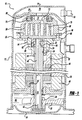
- Figure 1 is a vertical cross-sectional view through the center of a scroll-type refrigeration compressor incorporating the variable mass counterweights in accordance with the present invention
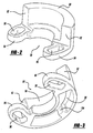
- Figure 2 is a perspective view looking down on the counterweight illustrated in Figure 1 and the mold or die used to manufacture the counterweight;
- Figure 3 is a perspective view looking up on the counterweight and mold or die illustrated in Figure 2;
- Figure 4 is a view similar to Figure 3, but showing the counterweight having a different mass
- Figure 5 is a perspective view looking up on a counterweight and forming mold or die in accordance with another embodiment of the present invention.
- Figure 6 is a perspective view of a mold assembly which produces the counterweight illustrated in Figures 2 and 3;
- Figure 7 is a perspective view of a mold assembly which produces the counterweight illustrated in Figure 5.
- the balancing system of the present invention is applicable to any type of rotary apparatus.
- the present invention is described in conjunction with a rotary compressor and, in particular, with a scroll-type refrigerant compressor.
- FIG. 1 a scroll compressor which incorporates the balancing system in accordance with the present invention which is designated generally by reference numeral 10.
- Compressor 10 comprises a generally cylindrical hermetic shell 12 having welded at the upper end thereof a cap 14 and at the lower end thereof a base 16 having a plurality of mounting feet (not shown) integrally formed therewith.
- Cap 14 is provided with a refrigerant discharge fitting 18 which may have the usual discharge valve therein (not shown).
- a transversely extending partition 22 which is welded about its periphery at the same point that cap 14 is welded to shell 12 a main bearing housing 24 which is suitably secured to shell 12 and a lower bearing housing 26 also having a plurality of radially outwardly extending legs, each of which is also suitably secured to shell 12.
- a motor stator 28 which is generally square in cross-section but with the corners rounded off, is press fitted into shell 12. The flats between the rounded corners on the stator provide passageways between the stator and shell, which facilitate the return flow of lubricant from the top of the shell to the bottom.
- a drive shaft or crankshaft 30 having an eccentric crank pin 32 at the upper end thereof is rotatably journaled in a bearing 34 in main bearing housing 24, and a second bearing 36 in lower bearing housing 26.
- Crankshaft 30 has at the lower end a relatively large diameter concentric bore 38 which communicates with a radially outwardly included smaller diameter bore 40 extending upwardly therefrom to the top crankshaft 30. Disposed within bore 38 is a stirrer 42.
- the lower portion of the interior shell 12 defines an oil sump 44 which is filled with lubricating oil to a level slightly above the lower end of a rotor 46; and bore 38 acts as a pump to pump lubricating fluid up the crankshaft 30 and into bore 40, and ultimately to all of the various portions of the compressor which require lubrication.
- Crankshaft 30 is rotatively driven by an electric motor including stator 28, windings 48 passing therethrough and rotor 46 press fitted on the crankshaft 30 and having upper and lower counterweights 50 and 52, respectively.
- main bearing housing 24 The upper surface of main bearing housing 24 is provided with a flat thrust bearing surface 54 on which is disposed an orbiting scroll member 56 having the usual spiral vane or wrap 58 on the upper surface thereof.
- orbiting scroll member 56 Projecting downwardly from the lower surface of orbiting scroll member 56 is a cylindrical hub having a journal bearing 60 therein, and in which is rotatively disposed a drive bushing 62 having an inner bore 64 in which crank pin 32 is drivingly disposed.
- Crank pin 32 has a flat on one surface which drivingly engages a flat surface (not shown) formed in a portion of bore 64 to provide a radially compliant driving arrangement, such as shown in U.S. Pat. No. 4,877,382, the disclosure of which is hereby incorporated herein by reference.
- Oldham coupling 66 is also provided, positioned between orbiting scroll member 56 and main bearing housing 24, and keyed to orbiting scroll member 56 and a non-orbiting scroll member 68 to prevent rotational movement of orbiting scroll member 56.
- Oldham coupling 66 is preferably of the type disclosed in U.S. Pat. No. 5,320,506, the disclosure of which is hereby incorporated herein by reference.
- Non-orbiting scroll member 68 is also provided, having a wrap 70 positioned in meshing engagement with wrap 58 of orbiting scroll member 56.
- Non-orbiting scroll member 68 has a centrally disposed discharge passage 72 which communicates with an upwardly open recess 74 which, in turn, is in fluid communication with a discharge muffler chamber 76 defined by cap 14 and partition 22.
- An annular recess 78 is also formed in non-orbiting scroll member 68 within which is disposed a seal assembly 80.
- Recesses 74 and 78 and seal assembly 80 cooperate to define axial pressure biasing chambers which receive pressurized fluid being compressed by wraps 58 and 70 so as to exert an axial biasing force on non-orbiting scroll member 68 to thereby urge the tips of respective wraps 58, 70 into sealing engagement with the opposed end plate surfaces.
- Seal assembly 80 is preferably of the type described in greater detail in U.S. Pat. No. 5,156,539, the disclosure of which is hereby incorporated herein by reference.
- Non-orbiting scroll member 68 is designed to be mounted to main bearing housing 24 in a suitable manner such as disclosed in the aforementioned U.S. Pat. No. 4,877,382 or U.S. Pat. No. 5,102, 316, the disclosure of which is hereby incorporated herein by reference.
- upper counterweight 50 is illustrated in greater detail. While the present invention is being described in relation to upper counterweight 50, it is within the scope of the present invention to incorporate the variable mass characteristics of upper counterweight 50 into lower counterweight 52, if desired.
- Upper counterweight 50 is stepped and it comprises a semicircular C-shaped section or main body 90 having circumferentially opposite end faces 92 and a pair of opposite circumferentially extended flange positions 94, each including an opening 96 which is utilized to secure counterweight 50 to rotor 46.
- C-shaped section 90 has an arcuate body portion between end faces 92 which extends circumferentially through an arc of up to, but not exceeding, 180° so as to be disposed entirely on one side of a plane extending along the axis of rotation of rotor 46.
- Flange portions 94 extend circumferentially from the juncture of end faces 92 to define an angular extension exceeding 180°.
- C-shaped section 90 defines a cavity or recess 98 which is utilized to achieve a specified mass for counterweight 50.
- Recess 98 extends over a specified arc and it has a specified depth. Both the length of the arc and the depth of the recess can be varied by having different interchangeable cores 100 ( Figure 6), which are inserted into a mold or die 102 ( Figure 6), which is utilized to manufacture counterweight 50.
- one or more ribs 104 can be formed to extend into recess 98 to adjust the mass of counterweight 50 to the specified mass.
- Counterweight 50' illustrated in Figure 4 has an increased mass when compared to the mass of counterweight 50 due to the shorter arc of recess 98, the shorter depth of recess 98 and the addition of one or more ribs 104. This is accomplished by having a different core or pin 100.
- the exterior configuration of counterweights 50 and 50' are identical, thus allowing both counterweights 50 and 50' to be manufactured in the same mold or die 102 ( Figure 6) with different cores 100 being utilized to define the different sizes of recess 98.
- Counterweight 50' would replace counterweight 50 when the operating characteristics of compressor 10 change, with the change in operating characteristics requiring rebalancing of compressor 10.
- Counterweight 150 is illustrated in accordance with another embodiment of the present invention.
- Counterweight 150 is the same as counterweight 50, except that recess 98 has been replaced with a plurality of holes 198.
- the plurality of holes 198 are circumferentially spaced along C-shaped section 90 and each of them has a specified depth. Both the number of holes 198 and the depth of each hole 198 can be independently varied by having a core 200 ( Figure 7) having different numbers and lengths of pins 200, which are inserted into the mold or die 102 ( Figure 7), which is utilized to manufacture counterweights 150.
- counterweights having common outer dimensions can be manufactured in different masses. This feature reduces the costs associated with additional plant capital.
- Prior art designs of counterweights vary by height and/or diameter thus requiring the assembly tooling for the counterweight to be modified or replaced when different masses of counterweights are used.
- communizing the outer dimensions for a plurality of counterweight masses a single set of assembly equipment can be utilized for all of the plurality of counterweight masses.
Landscapes
- Engineering & Computer Science (AREA)
- General Engineering & Computer Science (AREA)
- Mechanical Engineering (AREA)
- Physics & Mathematics (AREA)
- Power Engineering (AREA)
- Fluid Mechanics (AREA)
- Acoustics & Sound (AREA)
- Aviation & Aerospace Engineering (AREA)
- Rotary Pumps (AREA)
- Structures Of Non-Positive Displacement Pumps (AREA)
Abstract
Description
- The present invention relates to the balancing of rotary machines. More particularly, the present invention relates to counterweights which are used to balance rotary machines where the counterweight includes a variable sized cavity which is used to optimize the mass of the counterweight.
- A class of machines exists in the art generally known as "scroll" apparatus for the displacement of various types of fluids. Such apparatus may be configured as an expander, a displacement engine, a pump, a compressor, etc., and many features of the present invention are applicable to any one of these machines. For purposes of illustration, however, the disclosed embodiments are in the form of a hermetic refrigerant compressor.
- Generally speaking, a scroll apparatus comprises two spiral scroll wraps of similar configuration, each mounted on a separate end plate to define a scroll member. The two scroll members are interfitted together with one of the scroll wraps being rotationally displaced 180' from the other. The apparatus operates by orbiting one scroll member (the "orbiting scroll") with respect to the other scroll member (the "fixed scroll" or "non-orbiting scroll") to make moving line contacts between the flanks of the respective wraps, defining moving isolated crescent-shaped pockets of fluid. The spirals are commonly formed as involutes of a circle, and ideally there is no relative rotation between the scroll members during operation; i.e., the motion is purely curvilinear translation (i.e., no rotation of any line in the body). The fluid pockets carry the fluid to be handled from a first zone in the scroll apparatus where a fluid inlet is provided, to a second zone in the apparatus where a fluid outlet is provided. The volume of a sealed pocket changes as it moves from the first zone to the second zone. At any one instant in time, there will be at least one pair of sealed pockets; and when there are several pairs of sealed pockets at one, each pair will have different volumes. In a compressor, the second zone is at a higher pressure than the first zone and is physically located centrally in the apparatus, the first zone being located at the outer periphery of the apparatus.
- Two types of contacts define the fluid pockets formed between the scroll members: axially extending tangential line contacts between the spiral faces or flanks of the wraps caused by radial forces ("flank sealing"), and area contacts caused by axial forces between the plane edge surfaces (the "tips") of each wrap and the opposite end plate ("tip sealing"). For high efficiency, good sealing must be achieved for both types of contacts.
- The concept of a scroll-type apparatus has, thus, been known for some time and has been recognized as having distinct advantages. For example, scroll machines have high isentropic and volumetric efficiency, and, hence, are relatively small and lightweight for a given capacity. They are quieter and more vibration-free than many compressors because they do not use large reciprocating parts (e.g., pistons, connecting rods, etc.), and because all fluid flow is in one direction with simultaneous compression in plural opposed pockets, there are less pressure-created vibrations. Such machines also tend to have high reliability and durability because of the relatively few moving parts utilized, the relatively low velocity of movement between the scrolls, and an inherent forgiveness to fluid contamination.
- The orbiting of the one scroll member with respect to the other scroll member creates an imbalance which is typically counteracted using one or more counterweights. When designing new compressors and/or redesigning and modifying existing compressors, it is sometimes necessary to design a new counterweight. The need for a new counterweight is typically required when the mass of the counterweight needs to be optimized for a specific application. Each time a new counterweight of a new mass is required, new molds for the counterweight of the specific mass must be developed. The development of the new molds incurs development time and capital costs associated with the new mold.
- The present invention provides the art with a counterweight which includes a recess. The size and/or depth of the recess can be varied to vary the mass of the counterweight. Thus, a counterweight having common outer dimensions can be manufactured in various masses by changing the size and/or depth of the recess in the counterweight to meet the required mass for the counterweight. The fact that counterweights having different masses can still maintain common outer dimensions eliminates the need for the tooling on the assembly line which assemble the counterweights to the compressor assembly to be modified and/or changed when different masses of counterweights are used.
- Further areas of applicability of the present invention will become apparent from the detailed description provided hereinafter. It should be understood that the detailed description and specific examples, while indicating the preferred embodiment of the invention, are intended for purposes of illustration only and are not intended to limit the scope of the invention.
- The present invention will become more fully understood from the detailed description and the accompanying drawings, wherein:
- Figure 1 is a vertical cross-sectional view through the center of a scroll-type refrigeration compressor incorporating the variable mass counterweights in accordance with the present invention;
- Figure 2 is a perspective view looking down on the counterweight illustrated in Figure 1 and the mold or die used to manufacture the counterweight;
- Figure 3 is a perspective view looking up on the counterweight and mold or die illustrated in Figure 2;
- Figure 4 is a view similar to Figure 3, but showing the counterweight having a different mass;
- Figure 5 is a perspective view looking up on a counterweight and forming mold or die in accordance with another embodiment of the present invention;
- Figure 6 is a perspective view of a mold assembly which produces the counterweight illustrated in Figures 2 and 3; and
- Figure 7 is a perspective view of a mold assembly which produces the counterweight illustrated in Figure 5.
- The following description of the preferred embodiment(s) is merely exemplary in nature and is in no way intended to limit the invention, its application, or uses.
- The balancing system of the present invention is applicable to any type of rotary apparatus. For exemplary purposes only, the present invention is described in conjunction with a rotary compressor and, in particular, with a scroll-type refrigerant compressor.
- Referring now to the drawings in which like reference numerals designate like or corresponding parts throughout the several views, there is shown in Figure 1 a scroll compressor which incorporates the balancing system in accordance with the present invention which is designated generally by
reference numeral 10.Compressor 10 comprises a generally cylindrical hermetic shell 12 having welded at the upper end thereof a cap 14 and at the lower end thereof abase 16 having a plurality of mounting feet (not shown) integrally formed therewith. Cap 14 is provided with a refrigerant discharge fitting 18 which may have the usual discharge valve therein (not shown). Other major elements affixed to the shell include a transversely extending partition 22, which is welded about its periphery at the same point that cap 14 is welded to shell 12 a main bearing housing 24 which is suitably secured to shell 12 and a lower bearinghousing 26 also having a plurality of radially outwardly extending legs, each of which is also suitably secured to shell 12. Amotor stator 28, which is generally square in cross-section but with the corners rounded off, is press fitted into shell 12. The flats between the rounded corners on the stator provide passageways between the stator and shell, which facilitate the return flow of lubricant from the top of the shell to the bottom. - A drive shaft or
crankshaft 30 having aneccentric crank pin 32 at the upper end thereof is rotatably journaled in abearing 34 in main bearing housing 24, and a second bearing 36 in lower bearinghousing 26.Crankshaft 30 has at the lower end a relatively large diameter concentric bore 38 which communicates with a radially outwardly includedsmaller diameter bore 40 extending upwardly therefrom to thetop crankshaft 30. Disposed within bore 38 is astirrer 42. The lower portion of the interior shell 12 defines anoil sump 44 which is filled with lubricating oil to a level slightly above the lower end of arotor 46; and bore 38 acts as a pump to pump lubricating fluid up thecrankshaft 30 and intobore 40, and ultimately to all of the various portions of the compressor which require lubrication. -
Crankshaft 30 is rotatively driven by an electricmotor including stator 28,windings 48 passing therethrough androtor 46 press fitted on thecrankshaft 30 and having upper andlower counterweights - The upper surface of main bearing housing 24 is provided with a flat
thrust bearing surface 54 on which is disposed an orbitingscroll member 56 having the usual spiral vane orwrap 58 on the upper surface thereof. Projecting downwardly from the lower surface of orbitingscroll member 56 is a cylindrical hub having a journal bearing 60 therein, and in which is rotatively disposed a drive bushing 62 having an inner bore 64 in whichcrank pin 32 is drivingly disposed.Crank pin 32 has a flat on one surface which drivingly engages a flat surface (not shown) formed in a portion of bore 64 to provide a radially compliant driving arrangement, such as shown in U.S. Pat. No. 4,877,382, the disclosure of which is hereby incorporated herein by reference. An Oldhamcoupling 66 is also provided, positioned between orbitingscroll member 56 and main bearing housing 24, and keyed to orbitingscroll member 56 and anon-orbiting scroll member 68 to prevent rotational movement of orbitingscroll member 56. Oldhamcoupling 66 is preferably of the type disclosed in U.S. Pat. No. 5,320,506, the disclosure of which is hereby incorporated herein by reference. -
Non-orbiting scroll member 68 is also provided, having awrap 70 positioned in meshing engagement withwrap 58 of orbitingscroll member 56.Non-orbiting scroll member 68 has a centrally disposeddischarge passage 72 which communicates with an upwardlyopen recess 74 which, in turn, is in fluid communication with adischarge muffler chamber 76 defined by cap 14 and partition 22. Anannular recess 78 is also formed innon-orbiting scroll member 68 within which is disposed aseal assembly 80.Recesses seal assembly 80 cooperate to define axial pressure biasing chambers which receive pressurized fluid being compressed bywraps non-orbiting scroll member 68 to thereby urge the tips ofrespective wraps Seal assembly 80 is preferably of the type described in greater detail in U.S. Pat. No. 5,156,539, the disclosure of which is hereby incorporated herein by reference.Non-orbiting scroll member 68 is designed to be mounted to main bearing housing 24 in a suitable manner such as disclosed in the aforementioned U.S. Pat. No. 4,877,382 or U.S. Pat. No. 5,102, 316, the disclosure of which is hereby incorporated herein by reference. - Referring now to Figures 2 and 3,
upper counterweight 50 is illustrated in greater detail. While the present invention is being described in relation toupper counterweight 50, it is within the scope of the present invention to incorporate the variable mass characteristics ofupper counterweight 50 intolower counterweight 52, if desired. -
Upper counterweight 50 is stepped and it comprises a semicircular C-shaped section ormain body 90 having circumferentially opposite end faces 92 and a pair of opposite circumferentially extended flange positions 94, each including anopening 96 which is utilized to securecounterweight 50 torotor 46. C-shapedsection 90 has an arcuate body portion between end faces 92 which extends circumferentially through an arc of up to, but not exceeding, 180° so as to be disposed entirely on one side of a plane extending along the axis of rotation ofrotor 46.Flange portions 94 extend circumferentially from the juncture of end faces 92 to define an angular extension exceeding 180°. - C-shaped
section 90 defines a cavity orrecess 98 which is utilized to achieve a specified mass forcounterweight 50.Recess 98 extends over a specified arc and it has a specified depth. Both the length of the arc and the depth of the recess can be varied by having different interchangeable cores 100 (Figure 6), which are inserted into a mold or die 102 (Figure 6), which is utilized to manufacturecounterweight 50. In addition, one ormore ribs 104 can be formed to extend intorecess 98 to adjust the mass ofcounterweight 50 to the specified mass. Counterweight 50' illustrated in Figure 4 has an increased mass when compared to the mass ofcounterweight 50 due to the shorter arc ofrecess 98, the shorter depth ofrecess 98 and the addition of one ormore ribs 104. This is accomplished by having a different core orpin 100. The exterior configuration ofcounterweights 50 and 50' are identical, thus allowing bothcounterweights 50 and 50' to be manufactured in the same mold or die 102 (Figure 6) withdifferent cores 100 being utilized to define the different sizes ofrecess 98. Counterweight 50' would replacecounterweight 50 when the operating characteristics ofcompressor 10 change, with the change in operating characteristics requiring rebalancing ofcompressor 10. - Referring now to Figure 5, a
counterweight 150 is illustrated in accordance with another embodiment of the present invention.Counterweight 150. is the same ascounterweight 50, except thatrecess 98 has been replaced with a plurality ofholes 198. The plurality ofholes 198 are circumferentially spaced along C-shapedsection 90 and each of them has a specified depth. Both the number ofholes 198 and the depth of eachhole 198 can be independently varied by having a core 200 (Figure 7) having different numbers and lengths ofpins 200, which are inserted into the mold or die 102 (Figure 7), which is utilized to manufacturecounterweights 150. - Thus, counterweights having common outer dimensions can be manufactured in different masses. This feature reduces the costs associated with additional plant capital. Prior art designs of counterweights vary by height and/or diameter thus requiring the assembly tooling for the counterweight to be modified or replaced when different masses of counterweights are used. By communizing the outer dimensions for a plurality of counterweight masses, a single set of assembly equipment can be utilized for all of the plurality of counterweight masses.
- The description of the invention is merely exemplary in nature and, thus, variations that do not depart from the gist of the invention are intended to be within the scope of the invention. Such variations are not to be regarded as a departure from the spirit and scope of the invention.
Claims (18)
- A counterweight for a drive shaft designed for use in each of a plurality of rotary machines having different balancing requirements, respectively, said counterweight comprising:a main body having an overall size and shape to fit within each of said plurality of rotary machines; anda recess in said body, said recess being of a volume selected to optimize the total mass of said counterweight for the particular rotary machine for which it is intended.
- The counterweight according to claim 1, wherein said recess comprises a plurality of holes.
- The counterweight according to claim 2, wherein the number of holes is chosen to provide said volume.
- The counterweight according to claim 2 or 3, wherein the depth of holes is chosen to provide said volume.
- The counterweight according to any one of the preceding claims, wherein said recess is an elongated cavity.
- The counterweight according to claim 5, wherein the length of said cavity is chosen to provide said volume.
- The counterweight according to claim 5 or 6, wherein the depth of said cavity is chosen to provide said volume.
- The counterweight according to any one of claims 5 to 7, wherein a rib is incorporated in said cavity to provide said volume.
- The counterweight according to any one of the preceding claims, wherein said drive shaft is driven by a motor having a stator and a rotor, said counterweight being designed to be attached to said rotor.
- The counterweight according to any one of the preceding claims, wherein said main body is an arcuate body.
- The counterweight according to claim 10 wherein said recess is an elongated arcuate cavity.
- A rotary machine comprising a counterweight according to claim 1.
- A rotary machine according to claim 12, wherein said rotary machine is a scroll machine comprising:a first scroll member having a first end plate and a first spiral wrap projecting outwardly from said first end plate; anda second scroll member having a second end plate and a second spiral wrap projecting outwardly from said second end plate, said second scroll wrap being intermeshed with said first scroll wrap;said drive shaft causing said scroll members to orbit relative to one another whereby said spiral wraps will create pockets of progressively changing volume between a suction pressure zone and a discharge pressure zone.
- A method of fabricating a counterweight for a drive shaft designed for use in each of a plurality of rotary machines having different balancing requirements, respectively, comprising:providing a mold for casting a body having an overall size and shape to fit within each of said plurality of rotary machines;inserting a core into said mold for forming a recess in said body, said mold being of a volume selected to form a recess which will optimize the total mass of said counterweight for the particular rotary machine for which it is intended; andcasting said counterweight.
- A method according to claim 14, wherein said core forms a plurality of holes.
- The method according to claim 15, wherein the number of holes is chosen to provide said volume.
- The method according to claim 14 or 15, wherein the depth of holes is chosen to provide said volume.
- The method according to any one of claims 14 to 17, wherein said recess is an elongated cavity.
Applications Claiming Priority (1)
| Application Number | Priority Date | Filing Date | Title |
|---|---|---|---|
| US11/020,004 US7390179B2 (en) | 2004-12-21 | 2004-12-21 | Scroll machine having counterweights with changeable cavity |
Publications (2)
| Publication Number | Publication Date |
|---|---|
| EP1674846A1 true EP1674846A1 (en) | 2006-06-28 |
| EP1674846B1 EP1674846B1 (en) | 2016-06-22 |
Family
ID=36169211
Family Applications (1)
| Application Number | Title | Priority Date | Filing Date |
|---|---|---|---|
| EP05254097.8A Expired - Lifetime EP1674846B1 (en) | 2004-12-21 | 2005-06-29 | Scroll machine having counterweights with changeable cavity |
Country Status (7)
| Country | Link |
|---|---|
| US (2) | US7390179B2 (en) |
| EP (1) | EP1674846B1 (en) |
| KR (1) | KR101213995B1 (en) |
| CN (2) | CN101614207B (en) |
| AU (1) | AU2005232325B2 (en) |
| BR (1) | BRPI0503352A (en) |
| TW (1) | TWI347396B (en) |
Families Citing this family (19)
| Publication number | Priority date | Publication date | Assignee | Title |
|---|---|---|---|---|
| US7390179B2 (en) * | 2004-12-21 | 2008-06-24 | Emerson Climate Technologies, Inc. | Scroll machine having counterweights with changeable cavity |
| US20080267799A1 (en) * | 2007-03-28 | 2008-10-30 | Samsung Gwangju Electronics Co., Ltd. | Hermetic type compressor |
| US20090092506A1 (en) * | 2007-10-09 | 2009-04-09 | Tecumseh Products Company | Rotor attachment for compressor |
| US8133300B1 (en) | 2008-07-31 | 2012-03-13 | S&R Compression, LLC | Systems and methods for oil/gas separation |
| JP2011074814A (en) * | 2009-09-30 | 2011-04-14 | Sanyo Electric Co Ltd | Rotary compressor and manufacturing method for the same |
| DE112011104267A5 (en) * | 2010-12-07 | 2013-10-10 | Ixetic Hückeswagen Gmbh | Coupling, rotor and assembly for a pump |
| US10233927B2 (en) * | 2012-03-23 | 2019-03-19 | Bitzer Kuehlmaschinenbau Gmbh | Scroll compressor counterweight with axially distributed mass |
| JP5413491B2 (en) * | 2012-07-30 | 2014-02-12 | ダイキン工業株式会社 | Rotating machine and compressor |
| KR20150083681A (en) * | 2014-01-10 | 2015-07-20 | 삼성전기주식회사 | Motor rotor and method for manufacturing the same |
| JP6520047B2 (en) * | 2014-10-29 | 2019-05-29 | ダイキン工業株式会社 | Motor and compressor using the same |
| KR102166766B1 (en) | 2015-08-11 | 2020-10-16 | 삼성전자주식회사 | Compressor |
| JP6422190B2 (en) | 2016-06-17 | 2018-11-14 | ミネベアミツミ株式会社 | Rotating device |
| US10476322B2 (en) * | 2016-06-27 | 2019-11-12 | Abb Schweiz Ag | Electrical machine |
| DE102017123083A1 (en) * | 2017-10-05 | 2019-04-11 | Vorwerk & Co. Interholding Gmbh | External rotor motor |
| DE102017123085A1 (en) * | 2017-10-05 | 2019-04-11 | Vorwerk & Co. Interholding Gmbh | External rotor motor |
| US20190154037A1 (en) * | 2017-11-21 | 2019-05-23 | Emerson Climate Technologies, Inc. | Compressor Having Counterweight |
| CN210053294U (en) * | 2019-07-24 | 2020-02-11 | 丹佛斯(天津)有限公司 | Balance block for compressor, motor for compressor and compressor |
| FR3116571B1 (en) | 2020-11-25 | 2024-03-15 | Danfoss Commercial Compressors | A counterweight for a scroll compressor |
| CN112901486B (en) * | 2021-01-25 | 2022-04-22 | 珠海格力节能环保制冷技术研究中心有限公司 | Move vortex dish balance structure, scroll compressor and air conditioner |
Citations (8)
| Publication number | Priority date | Publication date | Assignee | Title |
|---|---|---|---|---|
| JPS6070953A (en) * | 1983-09-26 | 1985-04-22 | Toshiba Corp | Manufacture of balance weight of rotor for motor |
| EP0317056A1 (en) * | 1987-11-20 | 1989-05-24 | Copeland Corporation | Rotor balancing |
| EP0470265A1 (en) * | 1990-02-27 | 1992-02-12 | Fanuc Ltd. | Balance structure of motor |
| US5386163A (en) * | 1993-01-07 | 1995-01-31 | Emerson Electric Co. | Counterweighted rotor |
| US5495885A (en) * | 1994-07-25 | 1996-03-05 | Tecumseh Products Company | Method for making rotor counterweight insert apparatus |
| EP0911537A1 (en) * | 1997-05-07 | 1999-04-28 | Fanuc Ltd | Rotary body construction |
| US6291920B1 (en) * | 2000-06-15 | 2001-09-18 | A. O. Smith Corporation | Motor counter weight attachment |
| US6305914B1 (en) * | 2000-03-27 | 2001-10-23 | Scroll Technologies | Counterweight of reduced size |
Family Cites Families (10)
| Publication number | Priority date | Publication date | Assignee | Title |
|---|---|---|---|---|
| US1705187A (en) * | 1920-05-27 | 1929-03-12 | Wickliffe Twyman B | Counterweight means for crank shafts and process of forming and attaching |
| US3157051A (en) * | 1963-02-18 | 1964-11-17 | Eastman Kodak Co | Construction, method, and apparatus for counterweight balancing |
| JPS5863388U (en) | 1981-10-26 | 1983-04-28 | 三菱電機株式会社 | Rotary electric compressor |
| FR2649051B1 (en) | 1989-07-03 | 1991-10-04 | Cousin Freres Sa | DEVICE FOR RETRIEVING ANGULAR GAMES ON MECHANISMS USED IN SEATS, IN PARTICULAR, OF AUTOMOBILES |
| US5437543A (en) * | 1992-11-26 | 1995-08-01 | Kabushiki Kaisha Toyoda Jidoshokki Seisakusho | Scroll type refrigerant compressor with means for improving airtight sealing of compression chambers |
| ATE199275T1 (en) | 1997-10-25 | 2001-03-15 | Orpu Gmbh | PUMP WITH A CUTTER |
| US6382298B2 (en) * | 1998-04-23 | 2002-05-07 | Donald G. Leith | Multi-piece crankshaft construction |
| US6173628B1 (en) * | 1998-04-23 | 2001-01-16 | Panther Machine, Inc. | Multi-piece crankshaft construction |
| US7435067B2 (en) * | 2004-12-17 | 2008-10-14 | Emerson Climate Technologies, Inc. | Scroll machine with brushless permanent magnet motor |
| US7390179B2 (en) * | 2004-12-21 | 2008-06-24 | Emerson Climate Technologies, Inc. | Scroll machine having counterweights with changeable cavity |
-
2004
- 2004-12-21 US US11/020,004 patent/US7390179B2/en not_active Expired - Lifetime
-
2005
- 2005-06-29 EP EP05254097.8A patent/EP1674846B1/en not_active Expired - Lifetime
- 2005-07-06 TW TW094122888A patent/TWI347396B/en not_active IP Right Cessation
- 2005-08-04 CN CN2009101604898A patent/CN101614207B/en not_active Expired - Lifetime
- 2005-08-04 CN CNB200510089585XA patent/CN100540911C/en not_active Expired - Lifetime
- 2005-08-08 KR KR1020050072136A patent/KR101213995B1/en not_active Expired - Fee Related
- 2005-08-08 BR BRPI0503352-7A patent/BRPI0503352A/en active Search and Examination
- 2005-11-14 AU AU2005232325A patent/AU2005232325B2/en not_active Ceased
-
2008
- 2008-05-21 US US12/124,554 patent/US7934914B2/en not_active Expired - Lifetime
Patent Citations (8)
| Publication number | Priority date | Publication date | Assignee | Title |
|---|---|---|---|---|
| JPS6070953A (en) * | 1983-09-26 | 1985-04-22 | Toshiba Corp | Manufacture of balance weight of rotor for motor |
| EP0317056A1 (en) * | 1987-11-20 | 1989-05-24 | Copeland Corporation | Rotor balancing |
| EP0470265A1 (en) * | 1990-02-27 | 1992-02-12 | Fanuc Ltd. | Balance structure of motor |
| US5386163A (en) * | 1993-01-07 | 1995-01-31 | Emerson Electric Co. | Counterweighted rotor |
| US5495885A (en) * | 1994-07-25 | 1996-03-05 | Tecumseh Products Company | Method for making rotor counterweight insert apparatus |
| EP0911537A1 (en) * | 1997-05-07 | 1999-04-28 | Fanuc Ltd | Rotary body construction |
| US6305914B1 (en) * | 2000-03-27 | 2001-10-23 | Scroll Technologies | Counterweight of reduced size |
| US6291920B1 (en) * | 2000-06-15 | 2001-09-18 | A. O. Smith Corporation | Motor counter weight attachment |
Non-Patent Citations (1)
| Title |
|---|
| PATENT ABSTRACTS OF JAPAN vol. 009, no. 208 (E - 338) 24 August 1985 (1985-08-24) * |
Also Published As
| Publication number | Publication date |
|---|---|
| AU2005232325A1 (en) | 2006-07-06 |
| US7934914B2 (en) | 2011-05-03 |
| EP1674846B1 (en) | 2016-06-22 |
| CN101614207A (en) | 2009-12-30 |
| AU2005232325B2 (en) | 2012-03-01 |
| US20080219872A1 (en) | 2008-09-11 |
| KR20060071294A (en) | 2006-06-26 |
| TWI347396B (en) | 2011-08-21 |
| CN101614207B (en) | 2011-10-19 |
| BRPI0503352A (en) | 2006-09-12 |
| CN1793662A (en) | 2006-06-28 |
| CN100540911C (en) | 2009-09-16 |
| US20060133945A1 (en) | 2006-06-22 |
| US7390179B2 (en) | 2008-06-24 |
| TW200622086A (en) | 2006-07-01 |
| KR101213995B1 (en) | 2012-12-20 |
Similar Documents
| Publication | Publication Date | Title |
|---|---|---|
| US7934914B2 (en) | Scroll machine having counterweights with changeable cavity | |
| CN100485165C (en) | Scroll machine with stepped guide sleeve | |
| AU771839B2 (en) | Scroll compressor | |
| EP1122436B1 (en) | Horizontal scroll compressor | |
| US8393882B2 (en) | Scroll compressor with rotary discharge valve | |
| EP2295805A1 (en) | Scroll compressor with vapor injection | |
| US6439867B1 (en) | Scroll compressor having a clearance for the oldham coupling | |
| US6231324B1 (en) | Oldham coupling for scroll machine | |
| US7435067B2 (en) | Scroll machine with brushless permanent magnet motor | |
| US6179591B1 (en) | Conical hub bearing for scroll machine | |
| EP1630421B1 (en) | Lubricant pump of a compressor | |
| AU2012203079B2 (en) | Counterweights for balancing rotary machines | |
| US6135736A (en) | Scroll machine with non-machined anti-thrust surface | |
| CN219327627U (en) | Scroll compressor having a rotor with a rotor shaft having a rotor shaft with a |
Legal Events
| Date | Code | Title | Description |
|---|---|---|---|
| PUAI | Public reference made under article 153(3) epc to a published international application that has entered the european phase |
Free format text: ORIGINAL CODE: 0009012 |
|
| AK | Designated contracting states |
Kind code of ref document: A1 Designated state(s): AT BE BG CH CY CZ DE DK EE ES FI FR GB GR HU IE IS IT LI LT LU MC NL PL PT RO SE SI SK TR |
|
| AX | Request for extension of the european patent |
Extension state: AL BA HR LV MK YU |
|
| 17P | Request for examination filed |
Effective date: 20061012 |
|
| RAP1 | Party data changed (applicant data changed or rights of an application transferred) |
Owner name: EMERSON CLIMATE TECHNOLOGIES, INC. |
|
| 17Q | First examination report despatched |
Effective date: 20061219 |
|
| AKX | Designation fees paid |
Designated state(s): DE FR |
|
| GRAP | Despatch of communication of intention to grant a patent |
Free format text: ORIGINAL CODE: EPIDOSNIGR1 |
|
| INTG | Intention to grant announced |
Effective date: 20160121 |
|
| GRAS | Grant fee paid |
Free format text: ORIGINAL CODE: EPIDOSNIGR3 |
|
| GRAA | (expected) grant |
Free format text: ORIGINAL CODE: 0009210 |
|
| AK | Designated contracting states |
Kind code of ref document: B1 Designated state(s): DE FR |
|
| REG | Reference to a national code |
Ref country code: FR Ref legal event code: PLFP Year of fee payment: 12 |
|
| REG | Reference to a national code |
Ref country code: DE Ref legal event code: R096 Ref document number: 602005049551 Country of ref document: DE |
|
| REG | Reference to a national code |
Ref country code: DE Ref legal event code: R097 Ref document number: 602005049551 Country of ref document: DE |
|
| PLBE | No opposition filed within time limit |
Free format text: ORIGINAL CODE: 0009261 |
|
| STAA | Information on the status of an ep patent application or granted ep patent |
Free format text: STATUS: NO OPPOSITION FILED WITHIN TIME LIMIT |
|
| 26N | No opposition filed |
Effective date: 20170323 |
|
| REG | Reference to a national code |
Ref country code: FR Ref legal event code: PLFP Year of fee payment: 13 |
|
| REG | Reference to a national code |
Ref country code: FR Ref legal event code: PLFP Year of fee payment: 14 |
|
| PGFP | Annual fee paid to national office [announced via postgrant information from national office to epo] |
Ref country code: DE Payment date: 20240521 Year of fee payment: 20 |
|
| PGFP | Annual fee paid to national office [announced via postgrant information from national office to epo] |
Ref country code: FR Payment date: 20240521 Year of fee payment: 20 |
|
| REG | Reference to a national code |
Ref country code: DE Ref legal event code: R071 Ref document number: 602005049551 Country of ref document: DE |