EP1674710A1 - Method for recirculating exhaust gases in a turbocharged engine and the relative turbocharged engine - Google Patents
Method for recirculating exhaust gases in a turbocharged engine and the relative turbocharged engine Download PDFInfo
- Publication number
- EP1674710A1 EP1674710A1 EP04106790A EP04106790A EP1674710A1 EP 1674710 A1 EP1674710 A1 EP 1674710A1 EP 04106790 A EP04106790 A EP 04106790A EP 04106790 A EP04106790 A EP 04106790A EP 1674710 A1 EP1674710 A1 EP 1674710A1
- Authority
- EP
- European Patent Office
- Prior art keywords
- engine
- line
- fact
- exhaust gases
- exhaust
- Prior art date
- Legal status (The legal status is an assumption and is not a legal conclusion. Google has not performed a legal analysis and makes no representation as to the accuracy of the status listed.)
- Granted
Links
- 239000007789 gas Substances 0.000 title claims abstract description 52
- 238000000034 method Methods 0.000 title claims abstract description 17
- 230000003134 recirculating effect Effects 0.000 title claims abstract description 9
- 238000011144 upstream manufacturing Methods 0.000 claims abstract description 11
- 238000002485 combustion reaction Methods 0.000 claims description 10
- 238000001816 cooling Methods 0.000 claims 1
- MWUXSHHQAYIFBG-UHFFFAOYSA-N nitrogen oxide Inorganic materials O=[N] MWUXSHHQAYIFBG-UHFFFAOYSA-N 0.000 description 3
- 230000015572 biosynthetic process Effects 0.000 description 1
- 230000006835 compression Effects 0.000 description 1
- 238000007906 compression Methods 0.000 description 1
- 230000001276 controlling effect Effects 0.000 description 1
- 238000007796 conventional method Methods 0.000 description 1
- 239000003344 environmental pollutant Substances 0.000 description 1
- 239000000446 fuel Substances 0.000 description 1
- 239000002184 metal Substances 0.000 description 1
- 230000021715 photosynthesis, light harvesting Effects 0.000 description 1
- 231100000719 pollutant Toxicity 0.000 description 1
- 230000001105 regulatory effect Effects 0.000 description 1
- 238000009827 uniform distribution Methods 0.000 description 1
Images
Classifications
-
- F—MECHANICAL ENGINEERING; LIGHTING; HEATING; WEAPONS; BLASTING
- F02—COMBUSTION ENGINES; HOT-GAS OR COMBUSTION-PRODUCT ENGINE PLANTS
- F02B—INTERNAL-COMBUSTION PISTON ENGINES; COMBUSTION ENGINES IN GENERAL
- F02B37/00—Engines characterised by provision of pumps driven at least for part of the time by exhaust
- F02B37/013—Engines characterised by provision of pumps driven at least for part of the time by exhaust with exhaust-driven pumps arranged in series
-
- F—MECHANICAL ENGINEERING; LIGHTING; HEATING; WEAPONS; BLASTING
- F02—COMBUSTION ENGINES; HOT-GAS OR COMBUSTION-PRODUCT ENGINE PLANTS
- F02B—INTERNAL-COMBUSTION PISTON ENGINES; COMBUSTION ENGINES IN GENERAL
- F02B37/00—Engines characterised by provision of pumps driven at least for part of the time by exhaust
- F02B37/004—Engines characterised by provision of pumps driven at least for part of the time by exhaust with exhaust drives arranged in series
-
- F—MECHANICAL ENGINEERING; LIGHTING; HEATING; WEAPONS; BLASTING
- F02—COMBUSTION ENGINES; HOT-GAS OR COMBUSTION-PRODUCT ENGINE PLANTS
- F02M—SUPPLYING COMBUSTION ENGINES IN GENERAL WITH COMBUSTIBLE MIXTURES OR CONSTITUENTS THEREOF
- F02M26/00—Engine-pertinent apparatus for adding exhaust gases to combustion-air, main fuel or fuel-air mixture, e.g. by exhaust gas recirculation [EGR] systems
- F02M26/02—EGR systems specially adapted for supercharged engines
- F02M26/08—EGR systems specially adapted for supercharged engines for engines having two or more intake charge compressors or exhaust gas turbines, e.g. a turbocharger combined with an additional compressor
-
- F—MECHANICAL ENGINEERING; LIGHTING; HEATING; WEAPONS; BLASTING
- F02—COMBUSTION ENGINES; HOT-GAS OR COMBUSTION-PRODUCT ENGINE PLANTS
- F02M—SUPPLYING COMBUSTION ENGINES IN GENERAL WITH COMBUSTIBLE MIXTURES OR CONSTITUENTS THEREOF
- F02M26/00—Engine-pertinent apparatus for adding exhaust gases to combustion-air, main fuel or fuel-air mixture, e.g. by exhaust gas recirculation [EGR] systems
- F02M26/13—Arrangement or layout of EGR passages, e.g. in relation to specific engine parts or for incorporation of accessories
- F02M26/22—Arrangement or layout of EGR passages, e.g. in relation to specific engine parts or for incorporation of accessories with coolers in the recirculation passage
- F02M26/23—Layout, e.g. schematics
-
- F—MECHANICAL ENGINEERING; LIGHTING; HEATING; WEAPONS; BLASTING
- F02—COMBUSTION ENGINES; HOT-GAS OR COMBUSTION-PRODUCT ENGINE PLANTS
- F02B—INTERNAL-COMBUSTION PISTON ENGINES; COMBUSTION ENGINES IN GENERAL
- F02B29/00—Engines characterised by provision for charging or scavenging not provided for in groups F02B25/00, F02B27/00 or F02B33/00 - F02B39/00; Details thereof
- F02B29/04—Cooling of air intake supply
- F02B29/0406—Layout of the intake air cooling or coolant circuit
- F02B29/0412—Multiple heat exchangers arranged in parallel or in series
-
- F—MECHANICAL ENGINEERING; LIGHTING; HEATING; WEAPONS; BLASTING
- F02—COMBUSTION ENGINES; HOT-GAS OR COMBUSTION-PRODUCT ENGINE PLANTS
- F02B—INTERNAL-COMBUSTION PISTON ENGINES; COMBUSTION ENGINES IN GENERAL
- F02B3/00—Engines characterised by air compression and subsequent fuel addition
- F02B3/06—Engines characterised by air compression and subsequent fuel addition with compression ignition
-
- Y—GENERAL TAGGING OF NEW TECHNOLOGICAL DEVELOPMENTS; GENERAL TAGGING OF CROSS-SECTIONAL TECHNOLOGIES SPANNING OVER SEVERAL SECTIONS OF THE IPC; TECHNICAL SUBJECTS COVERED BY FORMER USPC CROSS-REFERENCE ART COLLECTIONS [XRACs] AND DIGESTS
- Y02—TECHNOLOGIES OR APPLICATIONS FOR MITIGATION OR ADAPTATION AGAINST CLIMATE CHANGE
- Y02T—CLIMATE CHANGE MITIGATION TECHNOLOGIES RELATED TO TRANSPORTATION
- Y02T10/00—Road transport of goods or passengers
- Y02T10/10—Internal combustion engine [ICE] based vehicles
- Y02T10/12—Improving ICE efficiencies
Definitions
- the present invention relates to a method for recirculating exhaust gases in a turbocharged engine, in particular in a two-stage turbocharged engine and, more particularly, in a diesel engine.
- Exhaust gas recirculation is common practice in the field of internal combustion engines. According to this system a portion of the exhaust gases from the engine are recirculated upstream of the engine and then reintroduced into the combustion chambers with the intake air. This permits to lower the combustion flame temperature and leads to a reduced formation of nitrogen oxides, one of the main pollutants in internal combustion engine emissions.
- a portion of the exhaust gases from the engine is withdrawn, upstream of the turbine/turbines that drives/drive the turbocharger compressor/compressors, and then reintroduced immediately upstream of the combustion chambers, downstream of the turbocharger compressor; according to other solutions the exhaust gases are withdrawn when leaving the turbocharger turbine and before entering the vehicle's muffler system and introduced into the air intake line upstream of the turbocharger compressor.
- a problem related to these systems is that the pressure in the area in which the exhaust gases to be recirculated are withdrawn is not, or is not always, lower than the pressure at the point where the exhaust gases are fed into the air intake line.
- a method for recirculating exhaust gases in a engine apparatus comprising an internal combustion engine, preferably a diesel engine, a first and second turbocharger compressor placed in series on an air intake line to said engine, method comprising withdrawal of a portion of the exhaust gases from the engine (also referred to as "recirculated gases") and its introduction into said intake line, between the outlet of the first compressor and the intake of the second.
- the method preferably comprises regulating the recirculation flow rate by means of a specific valve.
- the invention also relates to a engine apparatus comprising an internal combustion engine, preferably a diesel engine, an air intake line to said engine, a first and second turbocharged compressor placed in series on such intake line, an exhaust gas line from said engine, a first and a second turbine for driving said first and second compressor respectively, placed in series on such exhaust line and an exhaust gas recirculation line that connects a point on the exhaust line, between said engine and said turbines, with the intake line between said first and second compressor.
- an internal combustion engine preferably a diesel engine
- a first and second turbocharged compressor placed in series on such intake line
- an exhaust gas line from said engine a first and a second turbine for driving said first and second compressor respectively
- an exhaust gas recirculation line that connects a point on the exhaust line, between said engine and said turbines, with the intake line between said first and second compressor.
- the engine apparatus also comprises a control valve mounted on such recirculation line.
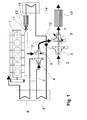
- the engine apparatus comprises an internal combustion engine 1, preferably a diesel engine, an air intake line 2 to the engine, that takes air from the outside, a first 3 and a second 4 compressor, placed in series on the intake line which perform a two-stage compression of the intake air and are driven by a first 5 and a second 6 turbine placed on the engine exhaust gas line 7 and driven by the exhaust gases, as in conventional two-stage turbocharged engines.
- the engine apparatus may also include the intake air coolers, one (intercooler) 8 mounted after the first compressor and the other (aftercooler) 9 after the second.
- a particulate trap 10 is advantageously mounted on the exhaust gas outlet.
- a portion of the exhaust gases are withdrawn after leaving the engine, for example from the exhaust gas manifold 11, and, in any case, preferably upstream of at least one of the turbines 5 and 6, and more preferably upstream of both, and then reintroduced into the intake line 7 at a point between the two compressors, upstream or downstream of the intercooler, preferably upstream to facilitate the lowering of the temperature of the gas supplied to the compressor 4.
- a specific recirculation line 12 connecting the withdrawal and introduction points.
- Said line is preferably equipped with a control valve 13; the method according to this invention may comprise the use of said valve to regulate the recirculation flow rate; such regulation may be achieved using methods already known in the field of exhaust gas recirculation.
- the recirculated gases pass through a particulate trap 15, before entering the intake line, especially if, as usual, there is an intercooler 8, and the recirculating gases are introduced into the intake line upstream of the intercooler. If the particulate in the recirculating gases is not removed it can settle in the intercooler or in the aftercooler.
- the trap 15 is preferably of a type that is capable of withstanding high exhaust gas temperatures; metal traps may be suitable for recirculated gases.
- the gas in order to make sure that the gas is supplied to the compressor 4 at the right temperature, it should preferably be cooled before being fed into the intake line 2, for example by means of a cooler on the recirculation line, preferably downstream of the trap 15.
- the method and engine according to this invention make exhaust gas recirculation possible without the need for any specific compressors or complex systems to induce pressure differences, which are sources of energy dissipation. They permit to control the flow rate properly by means of an appropriate valve, thanks to the pressure difference between the withdrawal and the reintroduction point, a natural consequence of the double expansion of the exhaust gases in the turbines.
- This method also eliminates the need to fully recompress the recirculating gas flow even if a particulate trap, a cooler and a gas flow rate control valve are provided on the recirculation line.
Landscapes
- Engineering & Computer Science (AREA)
- Chemical & Material Sciences (AREA)
- Combustion & Propulsion (AREA)
- Mechanical Engineering (AREA)
- General Engineering & Computer Science (AREA)
- Exhaust-Gas Circulating Devices (AREA)
- Supercharger (AREA)
Abstract
Description
- The present invention relates to a method for recirculating exhaust gases in a turbocharged engine, in particular in a two-stage turbocharged engine and, more particularly, in a diesel engine.
- Exhaust gas recirculation, or EGR, is common practice in the field of internal combustion engines. According to this system a portion of the exhaust gases from the engine are recirculated upstream of the engine and then reintroduced into the combustion chambers with the intake air. This permits to lower the combustion flame temperature and leads to a reduced formation of nitrogen oxides, one of the main pollutants in internal combustion engine emissions.
- According to a conventional method for recirculating exhaust gases in turbocharged engines a portion of the exhaust gases from the engine is withdrawn, upstream of the turbine/turbines that drives/drive the turbocharger compressor/compressors, and then reintroduced immediately upstream of the combustion chambers, downstream of the turbocharger compressor; according to other solutions the exhaust gases are withdrawn when leaving the turbocharger turbine and before entering the vehicle's muffler system and introduced into the air intake line upstream of the turbocharger compressor. A problem related to these systems is that the pressure in the area in which the exhaust gases to be recirculated are withdrawn is not, or is not always, lower than the pressure at the point where the exhaust gases are fed into the air intake line. As a result the flow rate of the recirculated gases is not always sufficient to achieve the required emission levels. A number of solutions have been developed to overcome this drawback. In the case of an EGR circuit on the high pressure side, when the intake pressure is not continuously higher than the exhaust pressure (pressure waves), check valves may be used. This is not an effective means of controlling recirculated gas flow rates or of obtaining an uniform distribution of the recirculated gases into the intake air, therefore venturi tubes are sometimes used to create, within a limited range of engine rpm and flow rates, the appropriate pressure in order to achieve the required exhaust gas flow rates. Variable geometry venturis, suitable for use in a wider range of engine speeds and gas flows, are also used. In the event of recirculation on the low pressure side, these devices are used in conjunction with valves that partially obstruct the cross-sectional area of the exhaust line in order to create back pressure and guarantee the passage of an adequate exhaust gas flow through the recirculation system.
- These problems are particularly serious in view of the fact that high exhaust gas recirculation rates are usually required (for example, in diesel engines the exhaust gas recirculation rate may be as high as 50% of all exhaust gases). Another solution foresees providing a specific compressor, which may be operated electrically, on the recirculation line. All these systems increase the complexity of the engine and result in dissipation of energy due to additional resistance or obstructions in the intake/exhaust systems, and also to the fact that they absorb a certain amount of power (compressor) and thus lead to a reduction in overall engine efficiency and an increase in fuel consumption.
- The problems described above have now been solved with a method for recirculating exhaust gases in a engine apparatus comprising an internal combustion engine, preferably a diesel engine, a first and second turbocharger compressor placed in series on an air intake line to said engine, method comprising withdrawal of a portion of the exhaust gases from the engine (also referred to as "recirculated gases") and its introduction into said intake line, between the outlet of the first compressor and the intake of the second. The method preferably comprises regulating the recirculation flow rate by means of a specific valve.
- The invention also relates to a engine apparatus comprising an internal combustion engine, preferably a diesel engine, an air intake line to said engine, a first and second turbocharged compressor placed in series on such intake line, an exhaust gas line from said engine, a first and a second turbine for driving said first and second compressor respectively, placed in series on such exhaust line and an exhaust gas recirculation line that connects a point on the exhaust line, between said engine and said turbines, with the intake line between said first and second compressor.
- According to a preferred embodiment of this invention, the engine apparatus also comprises a control valve mounted on such recirculation line.
- It is a particular object of the invention what is claimed in the appended claims.
- The invention will now be illustrated through a detailed description of preferred but not exclusive embodiments, furnished merely by way of example, with the aid of figure 1 attached hereto which illustrates the layout of a engine apparatus according to the invention.
- With reference to figure 1, the layout of a engine apparatus according to this invention is shown; the engine apparatus comprises an internal combustion engine 1, preferably a diesel engine, an
air intake line 2 to the engine, that takes air from the outside, a first 3 and a second 4 compressor, placed in series on the intake line which perform a two-stage compression of the intake air and are driven by a first 5 and a second 6 turbine placed on the engine exhaust gas line 7 and driven by the exhaust gases, as in conventional two-stage turbocharged engines. The engine apparatus may also include the intake air coolers, one (intercooler) 8 mounted after the first compressor and the other (aftercooler) 9 after the second. Aparticulate trap 10 is advantageously mounted on the exhaust gas outlet. - According to this invention, a portion of the exhaust gases are withdrawn after leaving the engine, for example from the
exhaust gas manifold 11, and, in any case, preferably upstream of at least one of the turbines 5 and 6, and more preferably upstream of both, and then reintroduced into the intake line 7 at a point between the two compressors, upstream or downstream of the intercooler, preferably upstream to facilitate the lowering of the temperature of the gas supplied to the compressor 4. For that purpose there may be aspecific recirculation line 12 connecting the withdrawal and introduction points. Said line is preferably equipped with acontrol valve 13; the method according to this invention may comprise the use of said valve to regulate the recirculation flow rate; such regulation may be achieved using methods already known in the field of exhaust gas recirculation. - According to a preferred embodiment, the recirculated gases pass through a
particulate trap 15, before entering the intake line, especially if, as usual, there is an intercooler 8, and the recirculating gases are introduced into the intake line upstream of the intercooler. If the particulate in the recirculating gases is not removed it can settle in the intercooler or in the aftercooler. Thetrap 15 is preferably of a type that is capable of withstanding high exhaust gas temperatures; metal traps may be suitable for recirculated gases. - Given the use of high recirculation rates, in order to make sure that the gas is supplied to the compressor 4 at the right temperature, it should preferably be cooled before being fed into the
intake line 2, for example by means of a cooler on the recirculation line, preferably downstream of thetrap 15. - The method and engine according to this invention make exhaust gas recirculation possible without the need for any specific compressors or complex systems to induce pressure differences, which are sources of energy dissipation. They permit to control the flow rate properly by means of an appropriate valve, thanks to the pressure difference between the withdrawal and the reintroduction point, a natural consequence of the double expansion of the exhaust gases in the turbines. This method also eliminates the need to fully recompress the recirculating gas flow even if a particulate trap, a cooler and a gas flow rate control valve are provided on the recirculation line.
Claims (10)
- Method for recirculating exhaust gases in a engine apparatus comprising an internal combustion engine (1), preferably a diesel engine, a first (3) and a second (4) turbocharger compressor placed in series on an air intake line (2) to said engine, method characterized by comprising withdrawal of a portion (also referred to as "recirculated gases") of the exhaust gases from the engine and the introduction of said portion into said intake line between the outlet of the first compressor and the intake of the second.
- Method according to claim 1, characterized by the fact that it comprises regulation of the flow of said portion of exhaust gases by means of a control valve (13).
- Method according to any of the previous claims characterized by the fact that it comprises the passage of such portion of exhaust gases through a particulate trap and the cooling of such gas (15) before being introduced into the intake line.
- Method according to any of the previous claims, characterized by the fact that said plant comprises an exhaust gas line (7) from said engine, a first (5) and a second turbine (6) for driving said first and second compressor respectively, wherein said portion of the exhaust gases are withdrawn from the exhaust line upstream of said turbines.
- Method according to any of the previous claims characterized by the fact that said engine is a diesel engine.
- Engine apparatus comprising an internal combustion engine (1), an air intake line (2) to said engine, a first (3) and a second (4) turbocharger compressor placed in series on said intake line, an exhaust gas line (7) from said engine, a first (5) and a second (6) turbine for driving said first and second compressor respectively, placed in series on said exhaust line, characterized by the fact that it comprises an exhaust gas recirculation line (12) that connects a point on the exhaust line, between the engine and said turbines, with the intake line between said first and second compressor.
- Engine apparatus according to claim 6, characterized by the fact that the engine is a diesel engine.
- Engine apparatus according to claim 6 or 7 characterized by the fact that it comprises a control valve (13) placed on such recirculation line.
- Engine apparatus according to any of the claims from 6 to 8, characterized by the fact that it comprises a particulate trap (15) and a cooler (14) placed on such recirculation line.
- Engine apparatus according to any of the claims from 6 to 9, characterized by the fact that it comprises an intercooler placed on the intake line between said first and second compressor.
Applications Claiming Priority (1)
| Application Number | Priority Date | Filing Date | Title |
|---|---|---|---|
| IT002559A ITMI20032559A1 (en) | 2003-12-22 | 2003-12-22 | METHOD PEARS THE RECIRCULATION OF EXHAUST GASES IN SUPERIMPOSED ENGINES AND OVER-POWERED ENGINE SYSTEM |
Publications (2)
| Publication Number | Publication Date |
|---|---|
| EP1674710A1 true EP1674710A1 (en) | 2006-06-28 |
| EP1674710B1 EP1674710B1 (en) | 2013-01-02 |
Family
ID=34930099
Family Applications (1)
| Application Number | Title | Priority Date | Filing Date |
|---|---|---|---|
| EP04106790A Expired - Lifetime EP1674710B1 (en) | 2003-12-22 | 2004-12-21 | Method for recirculating exhaust gases in a turbocharged engine and the relative turbocharged engine |
Country Status (3)
| Country | Link |
|---|---|
| EP (1) | EP1674710B1 (en) |
| ES (1) | ES2402287T3 (en) |
| IT (1) | ITMI20032559A1 (en) |
Cited By (4)
| Publication number | Priority date | Publication date | Assignee | Title |
|---|---|---|---|---|
| WO2008050178A1 (en) * | 2006-10-24 | 2008-05-02 | Renault Trucks | Internal combustion engine comprising an exhaust gas recirculation system |
| WO2008069743A1 (en) * | 2006-12-05 | 2008-06-12 | Scania Cv Ab (Publ) | Arrangement for a supercharged combustion engine |
| CN102155288A (en) * | 2011-02-22 | 2011-08-17 | 潍柴动力股份有限公司 | Double-supercharged diesel engine gas circuit |
| SE2251081A1 (en) * | 2022-09-19 | 2024-03-20 | Cetech Ab | An exhaust recirculation device for a 4-stroke compression ignition engine |
Citations (5)
| Publication number | Priority date | Publication date | Assignee | Title |
|---|---|---|---|---|
| JP2000213384A (en) * | 1999-01-26 | 2000-08-02 | Osaka Gas Co Ltd | Compression self ignition engine |
| JP2000220480A (en) * | 1999-01-28 | 2000-08-08 | Osaka Gas Co Ltd | Miller cycle engine |
| US6378308B1 (en) * | 1998-04-16 | 2002-04-30 | 3K Warner Turbosystems Gmbh | Turbocharged internal combustion engine |
| WO2004044412A1 (en) | 2002-11-13 | 2004-05-27 | Honeywell International Inc. | Dual and hybrid egr systems for use with turbocharged engine |
| DE10319594A1 (en) * | 2003-05-02 | 2004-11-18 | Daimlerchrysler Ag | Turbocharger device and a method for operating a turbocharger device |
-
2003
- 2003-12-22 IT IT002559A patent/ITMI20032559A1/en unknown
-
2004
- 2004-12-21 EP EP04106790A patent/EP1674710B1/en not_active Expired - Lifetime
- 2004-12-21 ES ES04106790T patent/ES2402287T3/en not_active Expired - Lifetime
Patent Citations (5)
| Publication number | Priority date | Publication date | Assignee | Title |
|---|---|---|---|---|
| US6378308B1 (en) * | 1998-04-16 | 2002-04-30 | 3K Warner Turbosystems Gmbh | Turbocharged internal combustion engine |
| JP2000213384A (en) * | 1999-01-26 | 2000-08-02 | Osaka Gas Co Ltd | Compression self ignition engine |
| JP2000220480A (en) * | 1999-01-28 | 2000-08-08 | Osaka Gas Co Ltd | Miller cycle engine |
| WO2004044412A1 (en) | 2002-11-13 | 2004-05-27 | Honeywell International Inc. | Dual and hybrid egr systems for use with turbocharged engine |
| DE10319594A1 (en) * | 2003-05-02 | 2004-11-18 | Daimlerchrysler Ag | Turbocharger device and a method for operating a turbocharger device |
Non-Patent Citations (1)
| Title |
|---|
| PATENT ABSTRACTS OF JAPAN vol. 2000, no. 11 3 January 2001 (2001-01-03) * |
Cited By (8)
| Publication number | Priority date | Publication date | Assignee | Title |
|---|---|---|---|---|
| WO2008050178A1 (en) * | 2006-10-24 | 2008-05-02 | Renault Trucks | Internal combustion engine comprising an exhaust gas recirculation system |
| US8061335B2 (en) | 2006-10-24 | 2011-11-22 | Renault Trucks | Internal combustion engine comprising an exhaust gas recirculation system |
| WO2008069743A1 (en) * | 2006-12-05 | 2008-06-12 | Scania Cv Ab (Publ) | Arrangement for a supercharged combustion engine |
| CN102155288A (en) * | 2011-02-22 | 2011-08-17 | 潍柴动力股份有限公司 | Double-supercharged diesel engine gas circuit |
| CN102155288B (en) * | 2011-02-22 | 2012-10-24 | 潍柴动力股份有限公司 | Double-supercharged diesel engine gas circuit |
| SE2251081A1 (en) * | 2022-09-19 | 2024-03-20 | Cetech Ab | An exhaust recirculation device for a 4-stroke compression ignition engine |
| WO2024063685A1 (en) * | 2022-09-19 | 2024-03-28 | Cetech Ab | An exhaust recirculation device for a 4-stroke compression ignition engine |
| SE546328C2 (en) * | 2022-09-19 | 2024-10-08 | Cetech Ab | An exhaust recirculation device for a 4-stroke compression ignition engine |
Also Published As
| Publication number | Publication date |
|---|---|
| ITMI20032559A1 (en) | 2005-06-23 |
| EP1674710B1 (en) | 2013-01-02 |
| ES2402287T3 (en) | 2013-04-30 |
Similar Documents
| Publication | Publication Date | Title |
|---|---|---|
| US6701710B1 (en) | Turbocharged engine with turbocharger compressor recirculation valve | |
| US6286312B1 (en) | Arrangement for a combustion engine | |
| US6981375B2 (en) | Turbocharged internal combustion engine with EGR flow | |
| US8302400B2 (en) | Internal combustion engine comprising an exhaust gas recirculation system | |
| US8297054B2 (en) | Exhaust system having turbo-assisted high-pressure EGR | |
| US7444815B2 (en) | EGR system for high EGR rates | |
| EP1689997B1 (en) | Dual and hybrid egr systems for use with turbocharged engine | |
| US20080223038A1 (en) | Arrangement for Recirculating and Cooling Exhaust Gas of an Internal Combustion Engine | |
| US20070175215A1 (en) | Constant EGR rate engine and method | |
| US20090260605A1 (en) | Staged arrangement of egr coolers to optimize performance | |
| EP2063097A1 (en) | Internal combustion engine having exhaust gas cooling in cooling jacket | |
| GB2418012A (en) | Working fluid circuit for a turbocharged engine having exhaust gas recirculation | |
| US6895752B1 (en) | Method and apparatus for exhaust gas recirculation cooling using a vortex tube to cool recirculated exhaust gases | |
| WO2008066594A1 (en) | Low pressure egr system having full range capability | |
| US8746217B2 (en) | Power system comprising an air cooled HT EGR cooler and LT EGR cooler | |
| US20170138252A1 (en) | Exhaust gas recirculation system for an internal combustion engine and method for operating such an exhaust gas recirculation system | |
| US20060059909A1 (en) | Supercharged internal combustion engine | |
| US7584748B2 (en) | Exhaust gas recirculation system for an internal combustion engine | |
| US7448368B2 (en) | Exhaust gas recirculation system for an internal combustion engine | |
| EP1674710B1 (en) | Method for recirculating exhaust gases in a turbocharged engine and the relative turbocharged engine | |
| EP3957848B1 (en) | Gas engine heat pump | |
| EP1870590A1 (en) | Internal combustion engine with a pump for exhaust gas recirculation | |
| WO2013010923A1 (en) | Exhaust gas recirculation for an i.c. engine | |
| CN219993807U (en) | Exhaust gas recirculation system and automobile | |
| JP2007077899A (en) | Two-stage turbocharging system |
Legal Events
| Date | Code | Title | Description |
|---|---|---|---|
| PUAI | Public reference made under article 153(3) epc to a published international application that has entered the european phase |
Free format text: ORIGINAL CODE: 0009012 |
|
| AK | Designated contracting states |
Kind code of ref document: A1 Designated state(s): AT BE BG CH CY CZ DE DK EE ES FI FR GB GR HU IE IS IT LI LT LU MC NL PL PT RO SE SI SK TR |
|
| AX | Request for extension of the european patent |
Extension state: AL BA HR LV MK YU |
|
| 17P | Request for examination filed |
Effective date: 20061221 |
|
| AKX | Designation fees paid |
Designated state(s): AT BE BG CH CY CZ DE DK EE ES FI FR GB GR HU IE IS IT LI LT LU MC NL PL PT RO SE SI SK TR |
|
| 17Q | First examination report despatched |
Effective date: 20090907 |
|
| RAP1 | Party data changed (applicant data changed or rights of an application transferred) |
Owner name: FIAT POWERTRAIN TECHNOLOGIES S.P.A. |
|
| RAP1 | Party data changed (applicant data changed or rights of an application transferred) |
Owner name: FPT INDUSTRIAL S.P.A. |
|
| GRAP | Despatch of communication of intention to grant a patent |
Free format text: ORIGINAL CODE: EPIDOSNIGR1 |
|
| GRAS | Grant fee paid |
Free format text: ORIGINAL CODE: EPIDOSNIGR3 |
|
| GRAA | (expected) grant |
Free format text: ORIGINAL CODE: 0009210 |
|
| AK | Designated contracting states |
Kind code of ref document: B1 Designated state(s): AT BE BG CH CY CZ DE DK EE ES FI FR GB GR HU IE IS IT LI LT LU MC NL PL PT RO SE SI SK TR |
|
| REG | Reference to a national code |
Ref country code: GB Ref legal event code: FG4D |
|
| REG | Reference to a national code |
Ref country code: CH Ref legal event code: EP Ref country code: AT Ref legal event code: REF Ref document number: 591765 Country of ref document: AT Kind code of ref document: T Effective date: 20130115 |
|
| REG | Reference to a national code |
Ref country code: IE Ref legal event code: FG4D |
|
| REG | Reference to a national code |
Ref country code: DE Ref legal event code: R096 Ref document number: 602004040609 Country of ref document: DE Effective date: 20130228 |
|
| REG | Reference to a national code |
Ref country code: CH Ref legal event code: NV Representative=s name: N&G PATENT SERVICES SA, CH |
|
| REG | Reference to a national code |
Ref country code: SE Ref legal event code: TRGR |
|
| REG | Reference to a national code |
Ref country code: ES Ref legal event code: FG2A Ref document number: 2402287 Country of ref document: ES Kind code of ref document: T3 Effective date: 20130430 |
|
| REG | Reference to a national code |
Ref country code: AT Ref legal event code: MK05 Ref document number: 591765 Country of ref document: AT Kind code of ref document: T Effective date: 20130102 |
|
| REG | Reference to a national code |
Ref country code: NL Ref legal event code: VDEP Effective date: 20130102 |
|
| PG25 | Lapsed in a contracting state [announced via postgrant information from national office to epo] |
Ref country code: SI Free format text: LAPSE BECAUSE OF FAILURE TO SUBMIT A TRANSLATION OF THE DESCRIPTION OR TO PAY THE FEE WITHIN THE PRESCRIBED TIME-LIMIT Effective date: 20130102 |
|
| REG | Reference to a national code |
Ref country code: LT Ref legal event code: MG4D |
|
| PG25 | Lapsed in a contracting state [announced via postgrant information from national office to epo] |
Ref country code: CZ Free format text: LAPSE BECAUSE OF FAILURE TO SUBMIT A TRANSLATION OF THE DESCRIPTION OR TO PAY THE FEE WITHIN THE PRESCRIBED TIME-LIMIT Effective date: 20130102 Ref country code: AT Free format text: LAPSE BECAUSE OF FAILURE TO SUBMIT A TRANSLATION OF THE DESCRIPTION OR TO PAY THE FEE WITHIN THE PRESCRIBED TIME-LIMIT Effective date: 20130102 Ref country code: BE Free format text: LAPSE BECAUSE OF FAILURE TO SUBMIT A TRANSLATION OF THE DESCRIPTION OR TO PAY THE FEE WITHIN THE PRESCRIBED TIME-LIMIT Effective date: 20130102 Ref country code: BG Free format text: LAPSE BECAUSE OF FAILURE TO SUBMIT A TRANSLATION OF THE DESCRIPTION OR TO PAY THE FEE WITHIN THE PRESCRIBED TIME-LIMIT Effective date: 20130402 Ref country code: LT Free format text: LAPSE BECAUSE OF FAILURE TO SUBMIT A TRANSLATION OF THE DESCRIPTION OR TO PAY THE FEE WITHIN THE PRESCRIBED TIME-LIMIT Effective date: 20130102 Ref country code: IS Free format text: LAPSE BECAUSE OF FAILURE TO SUBMIT A TRANSLATION OF THE DESCRIPTION OR TO PAY THE FEE WITHIN THE PRESCRIBED TIME-LIMIT Effective date: 20130502 |
|
| PG25 | Lapsed in a contracting state [announced via postgrant information from national office to epo] |
Ref country code: NL Free format text: LAPSE BECAUSE OF FAILURE TO SUBMIT A TRANSLATION OF THE DESCRIPTION OR TO PAY THE FEE WITHIN THE PRESCRIBED TIME-LIMIT Effective date: 20130102 Ref country code: PL Free format text: LAPSE BECAUSE OF FAILURE TO SUBMIT A TRANSLATION OF THE DESCRIPTION OR TO PAY THE FEE WITHIN THE PRESCRIBED TIME-LIMIT Effective date: 20130102 Ref country code: FI Free format text: LAPSE BECAUSE OF FAILURE TO SUBMIT A TRANSLATION OF THE DESCRIPTION OR TO PAY THE FEE WITHIN THE PRESCRIBED TIME-LIMIT Effective date: 20130102 Ref country code: PT Free format text: LAPSE BECAUSE OF FAILURE TO SUBMIT A TRANSLATION OF THE DESCRIPTION OR TO PAY THE FEE WITHIN THE PRESCRIBED TIME-LIMIT Effective date: 20130502 Ref country code: GR Free format text: LAPSE BECAUSE OF FAILURE TO SUBMIT A TRANSLATION OF THE DESCRIPTION OR TO PAY THE FEE WITHIN THE PRESCRIBED TIME-LIMIT Effective date: 20130403 |
|
| PG25 | Lapsed in a contracting state [announced via postgrant information from national office to epo] |
Ref country code: EE Free format text: LAPSE BECAUSE OF FAILURE TO SUBMIT A TRANSLATION OF THE DESCRIPTION OR TO PAY THE FEE WITHIN THE PRESCRIBED TIME-LIMIT Effective date: 20130102 Ref country code: RO Free format text: LAPSE BECAUSE OF FAILURE TO SUBMIT A TRANSLATION OF THE DESCRIPTION OR TO PAY THE FEE WITHIN THE PRESCRIBED TIME-LIMIT Effective date: 20130102 Ref country code: DK Free format text: LAPSE BECAUSE OF FAILURE TO SUBMIT A TRANSLATION OF THE DESCRIPTION OR TO PAY THE FEE WITHIN THE PRESCRIBED TIME-LIMIT Effective date: 20130102 Ref country code: SK Free format text: LAPSE BECAUSE OF FAILURE TO SUBMIT A TRANSLATION OF THE DESCRIPTION OR TO PAY THE FEE WITHIN THE PRESCRIBED TIME-LIMIT Effective date: 20130102 |
|
| PLBE | No opposition filed within time limit |
Free format text: ORIGINAL CODE: 0009261 |
|
| STAA | Information on the status of an ep patent application or granted ep patent |
Free format text: STATUS: NO OPPOSITION FILED WITHIN TIME LIMIT |
|
| PG25 | Lapsed in a contracting state [announced via postgrant information from national office to epo] |
Ref country code: CY Free format text: LAPSE BECAUSE OF FAILURE TO SUBMIT A TRANSLATION OF THE DESCRIPTION OR TO PAY THE FEE WITHIN THE PRESCRIBED TIME-LIMIT Effective date: 20130102 |
|
| 26N | No opposition filed |
Effective date: 20131003 |
|
| REG | Reference to a national code |
Ref country code: DE Ref legal event code: R097 Ref document number: 602004040609 Country of ref document: DE Effective date: 20131003 |
|
| PG25 | Lapsed in a contracting state [announced via postgrant information from national office to epo] |
Ref country code: MC Free format text: LAPSE BECAUSE OF FAILURE TO SUBMIT A TRANSLATION OF THE DESCRIPTION OR TO PAY THE FEE WITHIN THE PRESCRIBED TIME-LIMIT Effective date: 20130102 |
|
| PG25 | Lapsed in a contracting state [announced via postgrant information from national office to epo] |
Ref country code: LU Free format text: LAPSE BECAUSE OF FAILURE TO SUBMIT A TRANSLATION OF THE DESCRIPTION OR TO PAY THE FEE WITHIN THE PRESCRIBED TIME-LIMIT Effective date: 20131221 |
|
| REG | Reference to a national code |
Ref country code: IE Ref legal event code: MM4A |
|
| PG25 | Lapsed in a contracting state [announced via postgrant information from national office to epo] |
Ref country code: IE Free format text: LAPSE BECAUSE OF NON-PAYMENT OF DUE FEES Effective date: 20131221 |
|
| PG25 | Lapsed in a contracting state [announced via postgrant information from national office to epo] |
Ref country code: TR Free format text: LAPSE BECAUSE OF FAILURE TO SUBMIT A TRANSLATION OF THE DESCRIPTION OR TO PAY THE FEE WITHIN THE PRESCRIBED TIME-LIMIT Effective date: 20130102 |
|
| PG25 | Lapsed in a contracting state [announced via postgrant information from national office to epo] |
Ref country code: HU Free format text: LAPSE BECAUSE OF FAILURE TO SUBMIT A TRANSLATION OF THE DESCRIPTION OR TO PAY THE FEE WITHIN THE PRESCRIBED TIME-LIMIT; INVALID AB INITIO Effective date: 20041221 |
|
| REG | Reference to a national code |
Ref country code: FR Ref legal event code: PLFP Year of fee payment: 12 |
|
| REG | Reference to a national code |
Ref country code: FR Ref legal event code: PLFP Year of fee payment: 13 |
|
| REG | Reference to a national code |
Ref country code: FR Ref legal event code: PLFP Year of fee payment: 14 |
|
| PGFP | Annual fee paid to national office [announced via postgrant information from national office to epo] |
Ref country code: FR Payment date: 20171113 Year of fee payment: 14 Ref country code: DE Payment date: 20171212 Year of fee payment: 14 |
|
| PGFP | Annual fee paid to national office [announced via postgrant information from national office to epo] |
Ref country code: GB Payment date: 20171227 Year of fee payment: 14 Ref country code: SE Payment date: 20171213 Year of fee payment: 14 Ref country code: CH Payment date: 20171212 Year of fee payment: 14 |
|
| PGFP | Annual fee paid to national office [announced via postgrant information from national office to epo] |
Ref country code: ES Payment date: 20180102 Year of fee payment: 14 |
|
| REG | Reference to a national code |
Ref country code: DE Ref legal event code: R119 Ref document number: 602004040609 Country of ref document: DE |
|
| REG | Reference to a national code |
Ref country code: SE Ref legal event code: EUG |
|
| PG25 | Lapsed in a contracting state [announced via postgrant information from national office to epo] |
Ref country code: SE Free format text: LAPSE BECAUSE OF NON-PAYMENT OF DUE FEES Effective date: 20181222 |
|
| REG | Reference to a national code |
Ref country code: CH Ref legal event code: PL |
|
| GBPC | Gb: european patent ceased through non-payment of renewal fee |
Effective date: 20181221 |
|
| PG25 | Lapsed in a contracting state [announced via postgrant information from national office to epo] |
Ref country code: FR Free format text: LAPSE BECAUSE OF NON-PAYMENT OF DUE FEES Effective date: 20181231 Ref country code: DE Free format text: LAPSE BECAUSE OF NON-PAYMENT OF DUE FEES Effective date: 20190702 |
|
| PG25 | Lapsed in a contracting state [announced via postgrant information from national office to epo] |
Ref country code: GB Free format text: LAPSE BECAUSE OF NON-PAYMENT OF DUE FEES Effective date: 20181221 Ref country code: CH Free format text: LAPSE BECAUSE OF NON-PAYMENT OF DUE FEES Effective date: 20181231 Ref country code: LI Free format text: LAPSE BECAUSE OF NON-PAYMENT OF DUE FEES Effective date: 20181231 |
|
| REG | Reference to a national code |
Ref country code: ES Ref legal event code: FD2A Effective date: 20200203 |
|
| PG25 | Lapsed in a contracting state [announced via postgrant information from national office to epo] |
Ref country code: ES Free format text: LAPSE BECAUSE OF NON-PAYMENT OF DUE FEES Effective date: 20181222 |
|
| P01 | Opt-out of the competence of the unified patent court (upc) registered |
Effective date: 20230519 |
|
| PGFP | Annual fee paid to national office [announced via postgrant information from national office to epo] |
Ref country code: IT Payment date: 20231201 Year of fee payment: 20 |