EP1674671A2 - Composite fan containment case for turbine engines - Google Patents
Composite fan containment case for turbine engines Download PDFInfo
- Publication number
- EP1674671A2 EP1674671A2 EP05257854A EP05257854A EP1674671A2 EP 1674671 A2 EP1674671 A2 EP 1674671A2 EP 05257854 A EP05257854 A EP 05257854A EP 05257854 A EP05257854 A EP 05257854A EP 1674671 A2 EP1674671 A2 EP 1674671A2
- Authority
- EP
- European Patent Office
- Prior art keywords
- core
- fibers
- accordance
- braided
- composite fan
- Prior art date
- Legal status (The legal status is an assumption and is not a legal conclusion. Google has not performed a legal analysis and makes no representation as to the accuracy of the status listed.)
- Withdrawn
Links
Images

Classifications
-
- F—MECHANICAL ENGINEERING; LIGHTING; HEATING; WEAPONS; BLASTING
- F01—MACHINES OR ENGINES IN GENERAL; ENGINE PLANTS IN GENERAL; STEAM ENGINES
- F01D—NON-POSITIVE DISPLACEMENT MACHINES OR ENGINES, e.g. STEAM TURBINES
- F01D21/00—Shutting-down of machines or engines, e.g. in emergency; Regulating, controlling, or safety means not otherwise provided for
- F01D21/04—Shutting-down of machines or engines, e.g. in emergency; Regulating, controlling, or safety means not otherwise provided for responsive to undesired position of rotor relative to stator or to breaking-off of a part of the rotor, e.g. indicating such position
- F01D21/045—Shutting-down of machines or engines, e.g. in emergency; Regulating, controlling, or safety means not otherwise provided for responsive to undesired position of rotor relative to stator or to breaking-off of a part of the rotor, e.g. indicating such position special arrangements in stators or in rotors dealing with breaking-off of part of rotor
-
- D—TEXTILES; PAPER
- D04—BRAIDING; LACE-MAKING; KNITTING; TRIMMINGS; NON-WOVEN FABRICS
- D04C—BRAIDING OR MANUFACTURE OF LACE, INCLUDING BOBBIN-NET OR CARBONISED LACE; BRAIDING MACHINES; BRAID; LACE
- D04C1/00—Braid or lace, e.g. pillow-lace; Processes for the manufacture thereof
- D04C1/02—Braid or lace, e.g. pillow-lace; Processes for the manufacture thereof made from particular materials
-
- F—MECHANICAL ENGINEERING; LIGHTING; HEATING; WEAPONS; BLASTING
- F01—MACHINES OR ENGINES IN GENERAL; ENGINE PLANTS IN GENERAL; STEAM ENGINES
- F01D—NON-POSITIVE DISPLACEMENT MACHINES OR ENGINES, e.g. STEAM TURBINES
- F01D25/00—Component parts, details, or accessories, not provided for in, or of interest apart from, other groups
- F01D25/24—Casings; Casing parts, e.g. diaphragms, casing fastenings
-
- D—TEXTILES; PAPER
- D10—INDEXING SCHEME ASSOCIATED WITH SUBLASSES OF SECTION D, RELATING TO TEXTILES
- D10B—INDEXING SCHEME ASSOCIATED WITH SUBLASSES OF SECTION D, RELATING TO TEXTILES
- D10B2505/00—Industrial
- D10B2505/02—Reinforcing materials; Prepregs
-
- F—MECHANICAL ENGINEERING; LIGHTING; HEATING; WEAPONS; BLASTING
- F05—INDEXING SCHEMES RELATING TO ENGINES OR PUMPS IN VARIOUS SUBCLASSES OF CLASSES F01-F04
- F05D—INDEXING SCHEME FOR ASPECTS RELATING TO NON-POSITIVE-DISPLACEMENT MACHINES OR ENGINES, GAS-TURBINES OR JET-PROPULSION PLANTS
- F05D2300/00—Materials; Properties thereof
- F05D2300/40—Organic materials
- F05D2300/44—Resins
-
- F—MECHANICAL ENGINEERING; LIGHTING; HEATING; WEAPONS; BLASTING
- F05—INDEXING SCHEMES RELATING TO ENGINES OR PUMPS IN VARIOUS SUBCLASSES OF CLASSES F01-F04
- F05D—INDEXING SCHEME FOR ASPECTS RELATING TO NON-POSITIVE-DISPLACEMENT MACHINES OR ENGINES, GAS-TURBINES OR JET-PROPULSION PLANTS
- F05D2300/00—Materials; Properties thereof
- F05D2300/60—Properties or characteristics given to material by treatment or manufacturing
- F05D2300/603—Composites; e.g. fibre-reinforced
-
- F—MECHANICAL ENGINEERING; LIGHTING; HEATING; WEAPONS; BLASTING
- F05—INDEXING SCHEMES RELATING TO ENGINES OR PUMPS IN VARIOUS SUBCLASSES OF CLASSES F01-F04
- F05D—INDEXING SCHEME FOR ASPECTS RELATING TO NON-POSITIVE-DISPLACEMENT MACHINES OR ENGINES, GAS-TURBINES OR JET-PROPULSION PLANTS
- F05D2300/00—Materials; Properties thereof
- F05D2300/70—Treatment or modification of materials
- F05D2300/702—Reinforcement
-
- Y—GENERAL TAGGING OF NEW TECHNOLOGICAL DEVELOPMENTS; GENERAL TAGGING OF CROSS-SECTIONAL TECHNOLOGIES SPANNING OVER SEVERAL SECTIONS OF THE IPC; TECHNICAL SUBJECTS COVERED BY FORMER USPC CROSS-REFERENCE ART COLLECTIONS [XRACs] AND DIGESTS
- Y02—TECHNOLOGIES OR APPLICATIONS FOR MITIGATION OR ADAPTATION AGAINST CLIMATE CHANGE
- Y02T—CLIMATE CHANGE MITIGATION TECHNOLOGIES RELATED TO TRANSPORTATION
- Y02T50/00—Aeronautics or air transport
- Y02T50/60—Efficient propulsion technologies, e.g. for aircraft
Landscapes
- Engineering & Computer Science (AREA)
- Mechanical Engineering (AREA)
- General Engineering & Computer Science (AREA)
- Manufacturing & Machinery (AREA)
- Textile Engineering (AREA)
- Structures Of Non-Positive Displacement Pumps (AREA)
- Casting Or Compression Moulding Of Plastics Or The Like (AREA)
Abstract
Description
- This invention relates generally to gas turbine engines, and more particularly, to methods and apparatus for operating gas turbine engines.
- Gas turbine engines typically include high and low pressure compressors, a combustor, and at least one turbine. The compressors compress air which is mixed with fuel and channeled to the combustor. The mixture is then ignited for generating hot combustion gases, and the combustion gases are channeled to the turbine which extracts energy from the combustion gases for powering the compressor, as well as producing useful work to propel an aircraft in flight or to power a load, such as an electrical generator.
- When engines operate in various conditions, foreign objects may be ingested into the engine. More specifically, various types of foreign objects may be entrained in the inlet of a gas turbine engine, ranging from large birds, such as sea gulls, to hailstones, sand and rain. The foreign objects may impact a blade resulting in a portion of the impacted blade being torn loose from a rotor. Such a condition, known as foreign object damage, may cause the rotor blade to pierce an engine casing resulting in cracks along an exterior surface of the engine casing, and possible injury to nearby personnel. Additionally, the foreign object damage may cause a portion of the engine to bulge or deflect resulting in increased stresses along the entire engine casing.
- To facilitate preventing the increased engine stresses and the possible injury to personnel, at least some known engines include a metallic casing shell to facilitate increasing a radial and an axial stiffness of the engine, and to facilitate reducing stresses near the engine casing penetration. However, casing shells are typically fabricated from a metallic material which results in an increased weight of the engine and therefore the airframe.
- In one aspect of the invention, a composite fan casing for a gas turbine engine is provided. The casing includes a core having a plurality of core layers of reinforcing fiber bonded together with a thermosetting polymeric resin. Each core layer includes a plurality of braided reinforcing fibers with the braids of reinforcing fibers aligned in a circumferential direction.
- In another aspect of the invention, a method of fabricating a composite fan casing for a gas turbine engine is provided. The method includes forming a core having a plurality of core layers of reinforcing fiber bonded together with a thermosetting polymeric resin. Each core layer includes a plurality of braided reinforcing fibers formed from tows of fibers. The braids of reinforcing fibers are aligned in a circumferential direction.
- In another aspect of the invention, a method of fabricating a composite fan casing for a gas turbine engine is provided. The method includes forming a core having a plurality of core layers of reinforcing fiber bonded together with a thermosetting polymeric resin. Each core layer includes a plurality of braided reinforcing fibers formed from tows of fibers. The braids of reinforcing fibers are aligned in a circumferential direction. The method also includes bonding at least one build-up layer to at least one of an inner surface of the core and an outer surface of the core.
- The invention will now be described in greater detail, by way of example, with reference to the drawings, in which:-
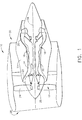
- Figure 1 is schematic illustration of a gas turbine engine.
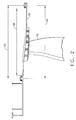
- Figure 2 is a schematic cross-section illustration of the fan containment case shown in Figure 1.
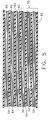
- Figure 3 is a schematic cross-section illustration of a portion of the fan containment case shown in Figure 2 in accordance with an exemplary embodiment.
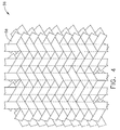
- Figure 4 is a schematic illustration of a braided mat of reinforcing fibers used to form the containment case shown in Figure 2.
- Figure 5 is a schematic cross-section illustration of a portion of the fan containment case shown in Figure 2 in accordance of another exemplary embodiment.
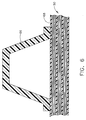
- Figure 6 is a schematic cross-section illustration of another embodiment of the fan containment case shown in Figure 2.
- A composite fan casing for a gas turbine engine is described below in detail. The casing includes a core having a plurality of core layers of reinforcing fiber bonded together with a thermosetting polymeric resin. Each core layer includes a plurality of braided reinforcing fibers with the braids of reinforcing fibers aligned in a circumferential direction. The composite casing resists crack propagation under impact loading. During impact, kinetic energy is dissipated by delamination of braided layers which then capture and contain the impact objects.
- Referring to the drawings, Figure 1 is a schematic illustration of a
gas turbine engine 10 that includes afan assembly 12 and acore engine 13 including ahigh pressure compressor 14, and acombustor 16.Engine 10 also includes ahigh pressure turbine 18, alow pressure turbine 20, and abooster 22.Fan assembly 12 includes an array offan blades 24 extending radially outward from arotor disc 26.Engine 10 has anintake side 28 and anexhaust side 30. In one embodiment, the gas turbine engine is a GE90 available from General Electric Company, Cincinnati, Ohio.Fan assembly 12 andturbine 20 are coupled by afirst rotor shaft 31, andcompressor 14 andturbine 18 are coupled by asecond rotor shaft 32. - During operation, air flows through
fan assembly 12, along acentral axis 34, and compressed air is supplied tohigh pressure compressor 14. The highly compressed air is delivered tocombustor 16. Airflow (not shown in Figure 1) fromcombustor 16drives turbines turbine 20drives fan assembly 12 by way ofshaft 31. - Figure 2 is a schematic cross-section illustration of a
fan containment casing 40, and Figure 3 is a schematic cross-section illustration of a portion offan containment case 40. Referring to Figures 2 and 3, in an exemplary embodiment,engine containment casing 40 is a hardwall containment system that includes alength 42 that is approximately equal to afan assembly length 44. More specifically,length 42 is variably sized so thatfan containment case 40 circumscribes aprime containment zone 46 offan assembly 12. Prime containment zone as used herein is defined a zone extending both axially and circumferentially aroundfan assembly 12 where a fan blade is most likely to be ejected fromfan assembly 12. - In the exemplary embodiment,
containment casing 40 includes acore 50 that is formed by a plurality ofcore layers 52 of reinforcing fibers bonded together by athermoset resin 54. Eachcore layer 52 includes a plurality of braids of the reinforcing fibers. Referring also to Figure 4, in one embodiment, the reinforcing fibers are braided into abraided mat 56 where the braids are aligned to extend in a circumferential direction. The braids are formed by braidingfiber tows 58 containing about 10,000 to about 30,000 fibers per tow. In alternateembodiments fiber tows 58 can contain less than 10,000 fibers or greater than 30,000 fibers. However, the strength ofcore 50 is reduced when the tows contain less than 10,000 fibers, and the weight ofcontainment casing 40 increases whenfiber tows 58 contain greater than 30,000 fibers. - Any suitable reinforcing fiber can be used to form
core layers 52, including, but not limited to, glass fibers, graphite fibers, carbon fibers, ceramic fibers, aromatic polyamid fibers, for example poly(p-phenylenetherephtalamide) fibers (KEVLAR fibers), and mixtures thereof. Any suitable thermosetting polymeric resin can be used in formingcore 50, for example, vinyl ester resin, polyester resins, acrylic resins, epoxy resins, polyurethane resins, and mixtures thereof. -
Fan containment casing 40 also includes a plurality of build-uplayers 60 bonded to aninner surface 62 ofcore 50. Build-uplayers 60 are formed fromspiral wound braids 64 of reinforcing fibers bonded together bythermoset 54. The spiral winding pattern of the braids of reinforcing fibers reduces layer drop off during impact which in turn reduces stress concentration. During impact, the kinetic energy is dissipated by delamination of build-uplayers 60 andcore layers 52. The delaminated build-uplayers 60 andcore layers 52 capture and contain impact objects. In another embodiment, shown in Figure 5, build-uplayers 60 are bonded to anouter surface 68 ofcore 50. In still another embodiment, build-up layers are bonded to bothouter surface 68 andinner surface 62 ofcore 50. - Referring to Figure 6, in another embodiment,
fan containment casing 40 includes at least onestiffener 66 bonded toouter surface 68 ofcore 50.Stiffeners 66 have a substantially inverted U-shape and are designed to break away fromcontainment case 40 during an impact event to relieve stress concentration incontainment case 40. In an alternative embodiment, stiffeners 66 have an I-shape.Stiffeners 66 can be formed from any suitable material, for example, fiber reinforced plastic materials. To provide more structural stiffness,stiffener 66 is formed with a high height to width ratio, and is designed to separate from casing 40 during impact. -
Fan containment casing 40 is fabricated, in the exemplary embodiment, by bonding together core layers 52 and build-uplayers 60 together with thermosettingpolymeric resin 54. Particularly, a mold is used to define the desired size and shape ofcontainment casing 40. Build-uplayers 60, core layers 52 andpolymeric resin 64 are positioned in the mold. A vacuum is applied to the layered structure in the mold by any suitable method, for example vacuum bagging, and heat is applied to the structure to curepolymeric resin 54. Heat is applied to the layered structure by any suitable method, for example, by placing the layered structure in a heat chamber, oven or autoclave. The vacuum pulls polymeric resin into and impregnatesfiber mats 56 to provide added strength tocontainment casing 40. - The above described composite
fan containment casing 40 has exceptional impact resistance and damage tolerance properties and provides significant weight savings compared to known metallic containment casing designs. Containment casing facilitates containing a released blade or blade part within the containment casing in the event a blade is released from the engine during operation.
Claims (10)
- A composite fan casing for a gas turbine engine, said casing comprising a core having a plurality of core layers of reinforcing fiber bonded together with a thermosetting polymeric resin, each said core layer comprising a plurality of braided reinforcing fibers, said braids of reinforcing fibers aligned in a circumferential direction.
- A composite fan casing in accordance with Claim 1 wherein each said core layer comprises a mat of braided reinforcing fibers.
- A composite fan casing in accordance with Claim 1 further comprising at least one buildup layer bonded to at least one of an inner surface of said core and an outer surface of said core, each said build-up layer comprising a plurality of braided reinforcing fibers, said braided fibers wound in a spiral pattern and bonded together with said thermosetting resin.
- A composite fan casing in accordance with Claim 1 further comprising at least one stiffener bonded to an outer surface of said core.
- A composite fan casing in accordance with Claim 1 wherein said reinforcing fibers comprise at least one of carbon fibers, graphite fibers, glass fibers, ceramic fibers, and aromatic polyamid fibers.
- A composite fan casing in accordance with Claim 1 wherein said thermosetting polymeric resin comprises at least one of vinyl ester resins, polyester resins, acrylic resins, epoxy resins, and polyurethane resins.
- A method of fabricating a composite fan casing for a gas turbine engine, said method comprises forming a core having a plurality of core layers of reinforcing fiber bonded together with a thermosetting polymeric resin, each core layer comprising a plurality of braided reinforcing fibers formed from tows of fibers, the braids of reinforcing fibers aligned in a circumferential direction.
- A method in accordance with Claim 7 wherein forming a core comprises forming a core having a plurality of core layers of braided reinforcing fiber mats bonded together with a thermosetting polymeric resin.
- A method in accordance with Claim 7 further comprising:forming at least one buildup layer comprising a plurality of braided reinforcing fibers, the braided fibers wound in a spiral pattern and bonded together with the thermosetting resin; andbonding the at least one build-up layer to at least one of an inner surface of the core and an outer surface of the core.
- A method in accordance with Claim 7 further comprising bonding at least one stiffener to an outer surface of the core.
Applications Claiming Priority (1)
| Application Number | Priority Date | Filing Date | Title |
|---|---|---|---|
| US11/020,483 US7246990B2 (en) | 2004-12-23 | 2004-12-23 | Composite fan containment case for turbine engines |
Publications (2)
| Publication Number | Publication Date |
|---|---|
| EP1674671A2 true EP1674671A2 (en) | 2006-06-28 |
| EP1674671A3 EP1674671A3 (en) | 2006-12-06 |
Family
ID=35773739
Family Applications (1)
| Application Number | Title | Priority Date | Filing Date |
|---|---|---|---|
| EP05257854A Withdrawn EP1674671A3 (en) | 2004-12-23 | 2005-12-20 | Composite fan containment case for turbine engines |
Country Status (3)
| Country | Link |
|---|---|
| US (2) | US7246990B2 (en) |
| EP (1) | EP1674671A3 (en) |
| JP (1) | JP5014626B2 (en) |
Cited By (19)
| Publication number | Priority date | Publication date | Assignee | Title |
|---|---|---|---|---|
| EP1830071A3 (en) * | 2006-03-03 | 2008-01-23 | WOCO Industrietechnik GmbH | Plastic compressor casing |
| EP1918531A2 (en) * | 2006-11-06 | 2008-05-07 | Rolls-Royce Deutschland Ltd & Co KG | Containment ring for the fan case of a gas turbine engine |
| EP1927728A2 (en) * | 2006-11-21 | 2008-06-04 | General Electric Company | Methods for reducing stress on composite structures |
| EP1961923A2 (en) | 2007-02-23 | 2008-08-27 | Snecma | Method of producing a gas turbine casing from a composite material and casing thus obtained. |
| DE102008062363A1 (en) * | 2008-12-17 | 2010-06-24 | Rolls-Royce Deutschland Ltd & Co Kg | Fan housing for a jet engine |
| US7862298B2 (en) | 2006-02-27 | 2011-01-04 | Woco Industrietechnik Gmbh | Centrifugal compressor housing |
| FR2966508A1 (en) * | 2010-10-22 | 2012-04-27 | Snecma | AERONAUTICAL MOTOR BLOWER CASING IN COMPOSITE MATERIAL AND METHOD FOR MANUFACTURING THE SAME |
| GB2492061A (en) * | 2011-06-15 | 2012-12-26 | Rolls Royce Plc | Rotor casing tip treatment bar comprising layered composite material |
| US8342800B2 (en) | 2007-02-27 | 2013-01-01 | Woco Industrietechnik Gmbh | Plastic compressor housing and method for producing same |
| US8419359B2 (en) | 2007-06-11 | 2013-04-16 | Woco Industrietechnik Gmbh | Plastic compressor housing and method for producing a plastic compressor housing |
| WO2013123195A1 (en) * | 2012-02-16 | 2013-08-22 | United Technologies Corporation | Case with ballistic liner |
| EP2813673A1 (en) * | 2013-06-13 | 2014-12-17 | Composite Industrie | Abradable ring seal sector for a turbomachine and method for manufacturing such a part |
| EP2071132A3 (en) * | 2007-12-12 | 2015-03-11 | General Electric Company | Composite containment casings |
| CN104471195A (en) * | 2012-07-16 | 2015-03-25 | 斯奈克玛 | Method for manufacturing a turbomachine casing from a composite material and associated casing |
| FR3012516A1 (en) * | 2013-10-30 | 2015-05-01 | Snecma | METALLIZING A CASING OF AN AERONAUTICAL MOTOR IN ELECTRICALLY INSULATING MATERIAL |
| CN104768734A (en) * | 2012-10-25 | 2015-07-08 | 株式会社Ihi | Cylindrical case and manufacturing method of cylindrical case |
| US9533454B2 (en) | 2013-06-13 | 2017-01-03 | Composite Industrie | Piece of abradable material for the manufacture of a segment of an abradable ring seal for a turbomachine, and process for the manufacture of such a piece |
| RU194933U1 (en) * | 2019-08-09 | 2019-12-30 | Публичное Акционерное Общество "Одк-Сатурн" | AIRCRAFT FAN HOUSING |
| CN110805480A (en) * | 2018-08-01 | 2020-02-18 | 通用电气公司 | Housing with non-axisymmetric composite wall |
Families Citing this family (72)
| Publication number | Priority date | Publication date | Assignee | Title |
|---|---|---|---|---|
| US7246990B2 (en) * | 2004-12-23 | 2007-07-24 | General Electric Company | Composite fan containment case for turbine engines |
| GB2426287B (en) * | 2005-05-18 | 2007-05-30 | Rolls Royce Plc | Blade containment structure |
| FR2903734B1 (en) * | 2006-07-12 | 2008-09-12 | Airbus France Sas | TURBOMOTEUR FOR AIRCRAFT. |
| FR2903733B1 (en) * | 2006-07-12 | 2011-03-04 | Airbus France | TURBOMOTEUR FOR AIRCRAFT. |
| US8475895B2 (en) * | 2006-11-21 | 2013-07-02 | General Electric Company | Articles comprising composite structures having mounting flanges |
| US20080116334A1 (en) * | 2006-11-21 | 2008-05-22 | Ming Xie | Methods for fabricating composite structures having mounting flanges |
| US20080115339A1 (en) * | 2006-11-21 | 2008-05-22 | Lee Alan Blanton | Apparatus for use with structures having mounting flanges |
| US7871486B2 (en) * | 2006-11-21 | 2011-01-18 | General Electric Company | Methods for making structures having mounting flanges |
| US8021102B2 (en) * | 2006-11-30 | 2011-09-20 | General Electric Company | Composite fan containment case and methods of fabricating the same |
| US7713021B2 (en) * | 2006-12-13 | 2010-05-11 | General Electric Company | Fan containment casings and methods of manufacture |
| US20080157418A1 (en) | 2006-12-27 | 2008-07-03 | Lee Alan Blanton | Methods for fabricating composite structures with flanges having tethered corners |
| US8016543B2 (en) * | 2007-04-02 | 2011-09-13 | Michael Scott Braley | Composite case armor for jet engine fan case containment |
| US8017188B2 (en) | 2007-04-17 | 2011-09-13 | General Electric Company | Methods of making articles having toughened and untoughened regions |
| US7914256B2 (en) * | 2007-04-17 | 2011-03-29 | General Electric Company | Articles made from composite materials having toughened and untoughened regions |
| US8092164B2 (en) * | 2007-08-30 | 2012-01-10 | United Technologies Corporation | Overlap interface for a gas turbine engine composite engine case |
| US9017814B2 (en) | 2007-10-16 | 2015-04-28 | General Electric Company | Substantially cylindrical composite articles and fan casings |
| US7905972B2 (en) * | 2007-10-16 | 2011-03-15 | General Electric Company | Methods for making substantially cylindrical articles and fan casings |
| US8046915B2 (en) * | 2007-12-12 | 2011-11-01 | General Electric Company | Methods for making composite containment casings |
| FR2925118B1 (en) * | 2007-12-14 | 2009-12-25 | Snecma | ABRADABLE SUPPORT PANEL IN A TURBOMACHINE |
| US8333558B2 (en) * | 2008-03-05 | 2012-12-18 | General Electric Company | Containment cases and method of manufacture |
| GB2459646B (en) * | 2008-04-28 | 2011-03-30 | Rolls Royce Plc | A fan assembly |
| US9032706B2 (en) * | 2008-09-26 | 2015-05-19 | Pratt & Whitney Canada Corp. | Composite fan case with integral containment zone |
| US8011877B2 (en) * | 2008-11-24 | 2011-09-06 | General Electric Company | Fiber composite reinforced aircraft gas turbine engine drums with radially inwardly extending blades |
| US8622731B2 (en) * | 2009-02-17 | 2014-01-07 | General Electric Company | Apparatus for forming flanges on components |
| US8545167B2 (en) * | 2009-08-26 | 2013-10-01 | Pratt & Whitney Canada Corp. | Composite casing for rotating blades |
| US9114882B2 (en) * | 2010-10-26 | 2015-08-25 | United Technologies Corporation | Fan case and mount ring snap fit assembly |
| US8672609B2 (en) | 2009-08-31 | 2014-03-18 | United Technologies Corporation | Composite fan containment case assembly |
| US8757958B2 (en) * | 2009-08-31 | 2014-06-24 | United Technologies Corporation | Composite fan containment case |
| US8827629B2 (en) | 2011-02-10 | 2014-09-09 | United Technologies Corporation | Case with ballistic liner |
| JP2011088363A (en) * | 2009-10-23 | 2011-05-06 | General Electric Co <Ge> | Spiral winding system for manufacturing composite material fan bypass duct and other similar component |
| JP5551411B2 (en) * | 2009-11-06 | 2014-07-16 | 株式会社Ihi | Case manufacturing method and case |
| US8986797B2 (en) * | 2010-08-04 | 2015-03-24 | General Electric Company | Fan case containment system and method of fabrication |
| GB201020143D0 (en) * | 2010-11-29 | 2011-01-12 | Rolls Royce Plc | A gas turbine engine blade containment arrangement |
| US8932002B2 (en) | 2010-12-03 | 2015-01-13 | Hamilton Sundstrand Corporation | Air turbine starter |
| US8889263B2 (en) | 2010-12-30 | 2014-11-18 | Rolls-Royce Corporation | Composite structure |
| US20130149103A1 (en) * | 2011-12-08 | 2013-06-13 | Honeywell International Inc. | Ballistic materials for enhanced energy absorption and fan casings including the same |
| US9248612B2 (en) | 2011-12-15 | 2016-02-02 | General Electric Company | Containment case and method of manufacture |
| US8918970B2 (en) * | 2011-12-21 | 2014-12-30 | GKN Aerospace Services Structures, Corp. | Hoop tow modification for a fabric preform for a composite component |
| US9249681B2 (en) * | 2012-01-31 | 2016-02-02 | United Technologies Corporation | Fan case rub system |
| US9200531B2 (en) | 2012-01-31 | 2015-12-01 | United Technologies Corporation | Fan case rub system, components, and their manufacture |
| JP5938474B2 (en) * | 2012-06-21 | 2016-06-22 | 川崎重工業株式会社 | Aircraft engine fan case |
| US20140003923A1 (en) * | 2012-07-02 | 2014-01-02 | Peter Finnigan | Functionally graded composite fan containment case |
| US9644493B2 (en) * | 2012-09-07 | 2017-05-09 | United Technologies Corporation | Fan case ballistic liner and method of manufacturing same |
| JP5945209B2 (en) * | 2012-10-25 | 2016-07-05 | 株式会社Ihi | Cylindrical case and manufacturing method of cylindrical case |
| US20140119904A1 (en) | 2012-11-01 | 2014-05-01 | United Technologies Corporation | In-situ pressure enhanced processing of composite articles |
| EP2971660B1 (en) | 2013-03-13 | 2019-05-01 | United Technologies Corporation | Thermally conforming acoustic liner cartridge for a gas turbine engine |
| US9249530B2 (en) | 2013-05-30 | 2016-02-02 | General Electric Company | Fiber preform architecture for composite articles and method of fabrication |
| EP3084143A1 (en) | 2013-12-17 | 2016-10-26 | General Electric Company | Composite fan inlet blade containment |
| GB201411657D0 (en) * | 2014-07-01 | 2014-08-13 | Rolls Royce Plc | Casing |
| AT516322B1 (en) * | 2014-10-10 | 2017-04-15 | Facc Ag | Flight case for an aircraft engine |
| US10107202B2 (en) | 2014-11-26 | 2018-10-23 | United Technologies Corporation | Composite fan housing assembly of a turbofan engine and method of manufacture |
| EP3247933A4 (en) | 2015-01-22 | 2018-10-24 | Neptune Research, Llc | Composite reinforcement systems and methods of manufacturing the same |
| US10030535B2 (en) * | 2015-07-17 | 2018-07-24 | Honeywell International Inc. | Composite structure with load distribution devices, and method for making same |
| US10125788B2 (en) | 2016-01-08 | 2018-11-13 | General Electric Company | Ceramic tile fan blade containment |
| US10519965B2 (en) * | 2016-01-15 | 2019-12-31 | General Electric Company | Method and system for fiber reinforced composite panels |
| US10697470B2 (en) | 2016-02-15 | 2020-06-30 | General Electric Company | Containment case trench filler layer and method of containing releasable components from rotatable machines |
| US10641287B2 (en) | 2016-09-06 | 2020-05-05 | Rolls-Royce Corporation | Fan containment case for a gas turbine engine |
| US10655500B2 (en) | 2016-09-06 | 2020-05-19 | Rolls-Royce Corporation | Reinforced fan containment case for a gas turbine engine |
| US11002294B2 (en) * | 2016-10-07 | 2021-05-11 | General Electric Comany | Impact force dispersal assembly for turbine engines and methods of fabricating the same |
| US10550718B2 (en) | 2017-03-31 | 2020-02-04 | The Boeing Company | Gas turbine engine fan blade containment systems |
| US10487684B2 (en) | 2017-03-31 | 2019-11-26 | The Boeing Company | Gas turbine engine fan blade containment systems |
| US10815804B2 (en) | 2017-04-04 | 2020-10-27 | General Electric Company | Turbine engine containment assembly and method for manufacturing the same |
| US10538856B2 (en) | 2017-05-02 | 2020-01-21 | General Electric Company | Apparatus and method for electro-polishing complex shapes |
| US11391297B2 (en) | 2017-11-09 | 2022-07-19 | Pratt & Whitney Canada Corp. | Composite fan case with nanoparticles |
| US11156126B2 (en) | 2018-04-13 | 2021-10-26 | Raytheon Technologies Corporation | Fan case with interleaved layers |
| GB201811543D0 (en) * | 2018-07-13 | 2018-08-29 | Rolls Royce Plc | Fan blade containment |
| US11499448B2 (en) * | 2019-05-29 | 2022-11-15 | General Electric Company | Composite fan containment case |
| US20210388739A1 (en) * | 2020-06-16 | 2021-12-16 | General Electric Company | Composite fan containment case |
| CN113914947B (en) * | 2020-07-08 | 2024-04-19 | 中国航发商用航空发动机有限责任公司 | Aeroengine fan containing device and aeroengine |
| US11549391B2 (en) * | 2021-03-22 | 2023-01-10 | General Electric Company | Component formed from hybrid material |
| FR3122900A1 (en) * | 2021-05-11 | 2022-11-18 | Safran Ventilation Systems | DEVICE FOR MAKING A FAN OR COMPRESSOR FOR THE AEROSPACE INDUSTRY |
| US11674405B2 (en) * | 2021-08-30 | 2023-06-13 | General Electric Company | Abradable insert with lattice structure |
Family Cites Families (12)
| Publication number | Priority date | Publication date | Assignee | Title |
|---|---|---|---|---|
| FR2467978A1 (en) | 1979-10-23 | 1981-04-30 | Snecma | RETENTION DEVICE FOR A COMPRESSOR CASE OF A TURBOMACHINE |
| EP0286815B1 (en) | 1987-04-15 | 1991-05-29 | Mtu Motoren- Und Turbinen-Union MàNchen Gmbh | Containment ring for turbo machine casings |
| CA2042198A1 (en) * | 1990-06-18 | 1991-12-19 | Stephen C. Mitchell | Projectile shield |
| US5344280A (en) * | 1993-05-05 | 1994-09-06 | General Electric Company | Impact resistant fan case liner |
| US5447411A (en) * | 1993-06-10 | 1995-09-05 | Martin Marietta Corporation | Light weight fan blade containment system |
| US5516257A (en) * | 1994-04-28 | 1996-05-14 | United Technologies Corporation | Aircraft fan containment structure restraint |
| US5431532A (en) * | 1994-05-20 | 1995-07-11 | General Electric Company | Blade containment system |
| US6435824B1 (en) | 2000-11-08 | 2002-08-20 | General Electric Co. | Gas turbine stationary shroud made of a ceramic foam material, and its preparation |
| US6428280B1 (en) | 2000-11-08 | 2002-08-06 | General Electric Company | Structure with ceramic foam thermal barrier coating, and its preparation |
| US6561760B2 (en) | 2001-08-17 | 2003-05-13 | General Electric Company | Booster compressor deicer |
| US7018168B2 (en) * | 2004-04-08 | 2006-03-28 | General Electric Company | Method and apparatus for fabricating gas turbine engines |
| US7246990B2 (en) * | 2004-12-23 | 2007-07-24 | General Electric Company | Composite fan containment case for turbine engines |
-
2004
- 2004-12-23 US US11/020,483 patent/US7246990B2/en active Active
-
2005
- 2005-11-16 US US11/274,972 patent/US7390161B2/en active Active
- 2005-12-20 EP EP05257854A patent/EP1674671A3/en not_active Withdrawn
- 2005-12-22 JP JP2005369002A patent/JP5014626B2/en not_active Expired - Fee Related
Non-Patent Citations (1)
| Title |
|---|
| None * |
Cited By (35)
| Publication number | Priority date | Publication date | Assignee | Title |
|---|---|---|---|---|
| US7862298B2 (en) | 2006-02-27 | 2011-01-04 | Woco Industrietechnik Gmbh | Centrifugal compressor housing |
| EP1830071A3 (en) * | 2006-03-03 | 2008-01-23 | WOCO Industrietechnik GmbH | Plastic compressor casing |
| EP1918531A2 (en) * | 2006-11-06 | 2008-05-07 | Rolls-Royce Deutschland Ltd & Co KG | Containment ring for the fan case of a gas turbine engine |
| EP1918531A3 (en) * | 2006-11-06 | 2010-04-21 | Rolls-Royce Deutschland Ltd & Co KG | Containment ring for the fan case of a gas turbine engine |
| EP1927728A2 (en) * | 2006-11-21 | 2008-06-04 | General Electric Company | Methods for reducing stress on composite structures |
| US8966754B2 (en) | 2006-11-21 | 2015-03-03 | General Electric Company | Methods for reducing stress on composite structures |
| EP1927728A3 (en) * | 2006-11-21 | 2014-04-30 | General Electric Company | Methods for reducing stress on composite structures |
| FR2913053A1 (en) * | 2007-02-23 | 2008-08-29 | Snecma Sa | PROCESS FOR MANUFACTURING A GAS TURBINE CASE OF COMPOSITE MATERIAL AND CARTER THUS OBTAINED |
| EP1961923A3 (en) * | 2007-02-23 | 2010-11-17 | Snecma | Method of producing a gas turbine casing from a composite material and casing thus obtained. |
| RU2450130C2 (en) * | 2007-02-23 | 2012-05-10 | Снекма | Method of producing gas turbine housing from composite material and housing thus made |
| US8322971B2 (en) | 2007-02-23 | 2012-12-04 | Snecma | Method of manufacturing a gas turbine casing out of composite material, and a casing as obtained thereby |
| EP1961923A2 (en) | 2007-02-23 | 2008-08-27 | Snecma | Method of producing a gas turbine casing from a composite material and casing thus obtained. |
| US8342800B2 (en) | 2007-02-27 | 2013-01-01 | Woco Industrietechnik Gmbh | Plastic compressor housing and method for producing same |
| US8419359B2 (en) | 2007-06-11 | 2013-04-16 | Woco Industrietechnik Gmbh | Plastic compressor housing and method for producing a plastic compressor housing |
| EP2071132A3 (en) * | 2007-12-12 | 2015-03-11 | General Electric Company | Composite containment casings |
| DE102008062363A1 (en) * | 2008-12-17 | 2010-06-24 | Rolls-Royce Deutschland Ltd & Co Kg | Fan housing for a jet engine |
| US8425178B2 (en) | 2008-12-17 | 2013-04-23 | Rolls-Royce Deutschland Ltd & Co Kg | Fan casing for a jet engine |
| US9017021B2 (en) | 2010-10-22 | 2015-04-28 | Snecma | Aeroengine fan casing made of composite material, and a method of fabricating it |
| FR2966508A1 (en) * | 2010-10-22 | 2012-04-27 | Snecma | AERONAUTICAL MOTOR BLOWER CASING IN COMPOSITE MATERIAL AND METHOD FOR MANUFACTURING THE SAME |
| GB2492061B (en) * | 2011-06-15 | 2014-08-13 | Rolls Royce Plc | Tip treatment for a rotor casing |
| GB2492061A (en) * | 2011-06-15 | 2012-12-26 | Rolls Royce Plc | Rotor casing tip treatment bar comprising layered composite material |
| US10724397B2 (en) | 2012-02-16 | 2020-07-28 | Raytheon Technologies Corporation | Case with ballistic liner |
| US9840936B2 (en) | 2012-02-16 | 2017-12-12 | United Technologies Corporation | Case with ballistic liner |
| WO2013123195A1 (en) * | 2012-02-16 | 2013-08-22 | United Technologies Corporation | Case with ballistic liner |
| CN104471195A (en) * | 2012-07-16 | 2015-03-25 | 斯奈克玛 | Method for manufacturing a turbomachine casing from a composite material and associated casing |
| CN104471195B (en) * | 2012-07-16 | 2016-08-17 | 斯奈克玛 | The method of turbines housing and relevant housing is manufactured from composite |
| CN104768734A (en) * | 2012-10-25 | 2015-07-08 | 株式会社Ihi | Cylindrical case and manufacturing method of cylindrical case |
| US9533454B2 (en) | 2013-06-13 | 2017-01-03 | Composite Industrie | Piece of abradable material for the manufacture of a segment of an abradable ring seal for a turbomachine, and process for the manufacture of such a piece |
| US9587506B2 (en) | 2013-06-13 | 2017-03-07 | Composite Industrie | Segment of an abradable ring seal for a turbomachine, and process for the manufacture of such a piece |
| FR3007064A1 (en) * | 2013-06-13 | 2014-12-19 | Composite Ind | ABRADABLE ANNULAR JOINT SECTOR FOR TURBOMACHINE AND METHOD OF MANUFACTURING SUCH A PART |
| EP2813673A1 (en) * | 2013-06-13 | 2014-12-17 | Composite Industrie | Abradable ring seal sector for a turbomachine and method for manufacturing such a part |
| FR3012516A1 (en) * | 2013-10-30 | 2015-05-01 | Snecma | METALLIZING A CASING OF AN AERONAUTICAL MOTOR IN ELECTRICALLY INSULATING MATERIAL |
| US9595774B2 (en) | 2013-10-30 | 2017-03-14 | Snecma | Metallisation of a housing of an aeronautic engine made of electrically insulating material |
| CN110805480A (en) * | 2018-08-01 | 2020-02-18 | 通用电气公司 | Housing with non-axisymmetric composite wall |
| RU194933U1 (en) * | 2019-08-09 | 2019-12-30 | Публичное Акционерное Общество "Одк-Сатурн" | AIRCRAFT FAN HOUSING |
Also Published As
| Publication number | Publication date |
|---|---|
| JP5014626B2 (en) | 2012-08-29 |
| US7246990B2 (en) | 2007-07-24 |
| US7390161B2 (en) | 2008-06-24 |
| JP2006177364A (en) | 2006-07-06 |
| US20060201135A1 (en) | 2006-09-14 |
| US20070081887A1 (en) | 2007-04-12 |
| EP1674671A3 (en) | 2006-12-06 |
Similar Documents
| Publication | Publication Date | Title |
|---|---|---|
| US7246990B2 (en) | Composite fan containment case for turbine engines | |
| US7713021B2 (en) | Fan containment casings and methods of manufacture | |
| US8021102B2 (en) | Composite fan containment case and methods of fabricating the same | |
| EP1584797A2 (en) | A containment apparatus for a gas turbine engine | |
| US8403624B2 (en) | Composite containment casings having an integral fragment catcher | |
| EP1462606B1 (en) | Multi-component hybrid turbine blade | |
| JP5974111B2 (en) | Composite storage case for gas turbine fan and manufacturing method thereof | |
| EP3003693B1 (en) | Fiber preform architecture for composite articles and method of fabrication | |
| EP2071132A2 (en) | Composite containment casings | |
| EP2070689A2 (en) | Methods for making composite containment casings | |
| US9309772B2 (en) | Hybrid turbine blade including multiple insert sections | |
| CA2645379C (en) | Methods for repairing composite containment casings | |
| EP3058199B1 (en) | Compression molded fiber reinforced fan case ice panel | |
| US20150118036A1 (en) | Fan case for aircraft engine | |
| CN112627979A (en) | Containing shell with ceramic coated fibers | |
| US20090151162A1 (en) | Methods for making composite containment casings having an integral fragment catcher | |
| JP5248097B2 (en) | Composite containment casing for turbine engine and method of manufacturing the same | |
| CN115111184A (en) | Component formed of mixed materials | |
| CN115539441A (en) | Composite airfoil with frangible tip |
Legal Events
| Date | Code | Title | Description |
|---|---|---|---|
| PUAI | Public reference made under article 153(3) epc to a published international application that has entered the european phase |
Free format text: ORIGINAL CODE: 0009012 |
|
| AK | Designated contracting states |
Kind code of ref document: A2 Designated state(s): AT BE BG CH CY CZ DE DK EE ES FI FR GB GR HU IE IS IT LI LT LU LV MC NL PL PT RO SE SI SK TR |
|
| AX | Request for extension of the european patent |
Extension state: AL BA HR MK YU |
|
| PUAL | Search report despatched |
Free format text: ORIGINAL CODE: 0009013 |
|
| AK | Designated contracting states |
Kind code of ref document: A3 Designated state(s): AT BE BG CH CY CZ DE DK EE ES FI FR GB GR HU IE IS IT LI LT LU LV MC NL PL PT RO SE SI SK TR |
|
| AX | Request for extension of the european patent |
Extension state: AL BA HR MK YU |
|
| 17P | Request for examination filed |
Effective date: 20070606 |
|
| AKX | Designation fees paid |
Designated state(s): DE FR GB |
|
| 17Q | First examination report despatched |
Effective date: 20070718 |
|
| GRAP | Despatch of communication of intention to grant a patent |
Free format text: ORIGINAL CODE: EPIDOSNIGR1 |
|
| INTG | Intention to grant announced |
Effective date: 20171120 |
|
| STAA | Information on the status of an ep patent application or granted ep patent |
Free format text: STATUS: THE APPLICATION IS DEEMED TO BE WITHDRAWN |
|
| 18D | Application deemed to be withdrawn |
Effective date: 20180404 |