EP1674660A2 - Impingement cooled turbine components with dirt separation - Google Patents
Impingement cooled turbine components with dirt separation Download PDFInfo
- Publication number
- EP1674660A2 EP1674660A2 EP05256498A EP05256498A EP1674660A2 EP 1674660 A2 EP1674660 A2 EP 1674660A2 EP 05256498 A EP05256498 A EP 05256498A EP 05256498 A EP05256498 A EP 05256498A EP 1674660 A2 EP1674660 A2 EP 1674660A2
- Authority
- EP
- European Patent Office
- Prior art keywords
- leading edge
- impingement
- radially outer
- air
- radially
- Prior art date
- Legal status (The legal status is an assumption and is not a legal conclusion. Google has not performed a legal analysis and makes no representation as to the accuracy of the status listed.)
- Granted
Links
Images

Classifications
-
- F—MECHANICAL ENGINEERING; LIGHTING; HEATING; WEAPONS; BLASTING
- F01—MACHINES OR ENGINES IN GENERAL; ENGINE PLANTS IN GENERAL; STEAM ENGINES
- F01D—NON-POSITIVE DISPLACEMENT MACHINES OR ENGINES, e.g. STEAM TURBINES
- F01D5/00—Blades; Blade-carrying members; Heating, heat-insulating, cooling or antivibration means on the blades or the members
- F01D5/12—Blades
- F01D5/14—Form or construction
- F01D5/18—Hollow blades, i.e. blades with cooling or heating channels or cavities; Heating, heat-insulating or cooling means on blades
- F01D5/187—Convection cooling
- F01D5/188—Convection cooling with an insert in the blade cavity to guide the cooling fluid, e.g. forming a separation wall
- F01D5/189—Convection cooling with an insert in the blade cavity to guide the cooling fluid, e.g. forming a separation wall the insert having a tubular cross-section, e.g. airfoil shape
-
- F—MECHANICAL ENGINEERING; LIGHTING; HEATING; WEAPONS; BLASTING
- F02—COMBUSTION ENGINES; HOT-GAS OR COMBUSTION-PRODUCT ENGINE PLANTS
- F02C—GAS-TURBINE PLANTS; AIR INTAKES FOR JET-PROPULSION PLANTS; CONTROLLING FUEL SUPPLY IN AIR-BREATHING JET-PROPULSION PLANTS
- F02C7/00—Features, components parts, details or accessories, not provided for in, or of interest apart form groups F02C1/00 - F02C6/00; Air intakes for jet-propulsion plants
- F02C7/04—Air intakes for gas-turbine plants or jet-propulsion plants
- F02C7/05—Air intakes for gas-turbine plants or jet-propulsion plants having provisions for obviating the penetration of damaging objects or particles
- F02C7/052—Air intakes for gas-turbine plants or jet-propulsion plants having provisions for obviating the penetration of damaging objects or particles with dust-separation devices
-
- F—MECHANICAL ENGINEERING; LIGHTING; HEATING; WEAPONS; BLASTING
- F02—COMBUSTION ENGINES; HOT-GAS OR COMBUSTION-PRODUCT ENGINE PLANTS
- F02C—GAS-TURBINE PLANTS; AIR INTAKES FOR JET-PROPULSION PLANTS; CONTROLLING FUEL SUPPLY IN AIR-BREATHING JET-PROPULSION PLANTS
- F02C7/00—Features, components parts, details or accessories, not provided for in, or of interest apart form groups F02C1/00 - F02C6/00; Air intakes for jet-propulsion plants
-
- F—MECHANICAL ENGINEERING; LIGHTING; HEATING; WEAPONS; BLASTING
- F05—INDEXING SCHEMES RELATING TO ENGINES OR PUMPS IN VARIOUS SUBCLASSES OF CLASSES F01-F04
- F05D—INDEXING SCHEME FOR ASPECTS RELATING TO NON-POSITIVE-DISPLACEMENT MACHINES OR ENGINES, GAS-TURBINES OR JET-PROPULSION PLANTS
- F05D2260/00—Function
- F05D2260/20—Heat transfer, e.g. cooling
- F05D2260/201—Heat transfer, e.g. cooling by impingement of a fluid
-
- F—MECHANICAL ENGINEERING; LIGHTING; HEATING; WEAPONS; BLASTING
- F05—INDEXING SCHEMES RELATING TO ENGINES OR PUMPS IN VARIOUS SUBCLASSES OF CLASSES F01-F04
- F05D—INDEXING SCHEME FOR ASPECTS RELATING TO NON-POSITIVE-DISPLACEMENT MACHINES OR ENGINES, GAS-TURBINES OR JET-PROPULSION PLANTS
- F05D2260/00—Function
- F05D2260/60—Fluid transfer
- F05D2260/607—Preventing clogging or obstruction of flow paths by dirt, dust, or foreign particles
Definitions
- This invention relates to an impingement tube received within a turbine component, and in which the impingement tube has an inner and outer portion, with the outer portion being configured to minimize dirt blockage of impingement air at the leading edge.
- the inner and outer portions are formed as separate pieces, and in another embodiment, the inner and outer portions are formed as a single piece.
- Turbine engines have a number of components.
- One type of component is a stationary vane.
- the vanes are in the path of hot air downstream of a combustor, and have a leading edge that faces the hot air.
- the vane is thus exposed to high temperatures and requires cooling.
- One method utilized to cool the vane is to form the vane to have hollow areas, and place impingement tubes within the hollow areas.
- the impingement tubes have a number of holes for directing impingement air outwardly to points within the vane. Holes also extend through the wall of the vane in order to direct the impingement air onto an outer surface of the vane.
- This application relates to an impingement tube used within the hollow area of the vane that receives cooling air from both inner and outer vane cooling air supplies.
- One known way of supplying impingement cooling air from both inner and outer supplies is to use an impingement tube which includes an outer portion and an inner portion. Each of the inner and outer portions have an end wall roughly at an intermediate position within the vane, and with end walls both being generally parallel to an axis of rotation for the turbine. Outer cooling air is brought within the outer portion and inner cooling air is brought within the inner portion. The holes within the impingement tube portions and the vane are concentrated adjacent the leading edge of the vane.
- the air from a radially outer source carries more dirt than air from a radially inner source.
- the holes in the impingement tube and vane are relatively small, and are sometimes clogged by dirt within the impingement airflow. When this dirt clogs the holes near the leading edge, less air than may be desirable is directed to the leading edge.
- a vane receives an impingement tube including an inner and an outer portion.
- end walls of the inner and outer portions are formed to be non-parallel relative to the axis of rotation of the turbine.
- an end wall within the outer portion is positioned such that the outer portion covers less of a leading edge of the vane than it covers at the aft end spaced towards the trailing edge.
- the end wall of the outer portion is generally planar, and angled radially inwardly from the leading edge moving toward trailing edge. In this manner, the outer portion has more surface area adjacent the aft end than it does at the leading edge.
- the dirtier outer impingement air flows in greater volumes to the aft end than it does to the leading edge.
- the inner portion is formed in an opposite manner, with its end wall also moving radially inwardly from the leading edge toward the trailing edge.
- this angled end wall is to increase the volume of air directed from the inner impingement air source to the leading edge relative to the volume of air directed to the aft end.
- the angled end wall "pins" the dirt at the aft end. This is due to a pressure loading from the wedge shape. Purge holes at the bottom of the wedge, in conjunction with the suppressed static pressure inherent to the decrease in area heading toward the aft edge, create an increased dynamic pressure load that resists movement of the dirt from the aft end toward the leading edge in the outer portion. Also, the angled end wall creates a wedge shape which acts as a mechanical means of trapping the dirt. The angled end wall first directs dirt to the aft end of the outer impingement tube where once there its is pinned both mechanically and from the resulting flow dynamics from movement toward the leading edge.
- the wedge shape creates a trap that either captures dirt permanently or allows the dirt to exit the vane adjacent the aft end where it is least likely of plugging the leading edge of the vane.
- the inner and outer portions are formed as separate pieces. In a second embodiment, the inner and outer portions are formed as a single piece.
- the present invention thus reduces the likelihood of the dirt within the outer airflow from reducing the impingement airflow to the leading edge of the vane.
- a gas turbine engine 20 is illustrated in Figure 1.
- rotor blades 22 rotate about a central axis, and receive air from an upstream combustor.
- a plurality of stationary vanes 24 are positioned adjacent the rotor blades 22.
- the vanes 24 are exposed to very hot air, and thus cooling air is directed into the vanes 24.
- the air exits the vanes 24 such as through film cooling holes 25 found at the leading edge. Other holes are found across the vane, but are not illustrated for simplicity.
- the radially outer source 28 directs air that carries more dirt into the vane 24 compared to the radially inner source 26.
- a radial line R which will be used as a reference below, could be described which is generally perpendicular to the rotational axis of the rotor blades 22.
- Figure 2A shows vane 24, having a leading edge 34, a rib 32 spaced toward a trailing edge 21, as well as inner and outer platforms 16 and 17, respectively.
- a hollow area 19 will receive one impingement tube, and another impingement tube is received in another hollow area and includes an outer portion 36 and an inner portion 40 adjacent the leading edge 34.
- the outer portion 36 has an end 38 and the inner portion 40 has an end 42.
- vane 24 includes an outer wall 30 at a leading edge 34.
- the leading edge 34 is exposed to the hottest temperatures, as it directly faces into the flow downstream of the combustor.
- the cooling air from the outer air source 28 is directed into the outer impingement tube portion 36 having an end wall 38.
- the inner impingement tube portion 40 receives air from the inner air source 26, and has an end wall 42.
- the end walls 38 and 42 are not perpendicular to the radius R, or stated otherwise, are not parallel to the rotational axis of the rotor blade 22. In the prior art, the end walls 38 and 42 have been parallel to the rotational axis of the rotor blade 22.
- the impingement tube portions 36 and 40 include a number of impingement airflow holes 44.
- the holes 44 are found across the impingement air tube portions 36 and 40, however, they are only illustrated adjacent the leading edge 34 in this application.
- the impingement air tube portions have a greater concentration of holes 44 adjacent the leading edge, as it is desirable to direct the most cooling air to the leading edge.
- other holes would be found spaced away from the leading edge of the impingement tube portions 36 and 40. These holes are simply not illustrated in these figures for simplicity of illustration.
- dirt D is found to a greater extent in the outer airflow source 28 than in the inner airflow source 26. In the past, this dirt has plugged holes such as holes 44 and 25. This is especially detrimental at the leading edge 34.
- the present invention addresses this concern in three ways. First, since the end wall 38 is angled from the leading edge inward toward the aft end 35, there is a dynamic pressure load on the dirt particles D resisting migration toward the leading edge. Second, due to the wedge shape created between aft end 35 and end wall 38 dirt will become trapped within the deep tight corner of the impingement tube or exit the aft end 35 instead of migrating toward the leading edge and plugging holes 25 and 44. Further, the simple geometry of the outer impingement tube portion 36 is such that there is less flow cross-sectional area adjacent the leading edge than there is adjacent the aft end edge. As can be appreciated from Figure 2, the opposite would be true of the radially inner impingement tube portion 40.
- the radially inner source 26 provides a greater volume of cooling air to the leading edge 34 than it does to the second end 35, while the radially outer source 28 supplies more impingement cooling air to the aft end 35 than it does the leading edge 34.
- An angle A measured between the end wall 38 and the aft end 35 of the outer impingement tube portion 36 is preferably between 20 and 60°. In one embodiment, the angle is 36°. It is important that the angle is small enough to collect the dirt, but not large enough to affect the cooling airflow through the impingement tube.
- the angle of the inner portion end 42 wall is parallel to end wall 38.
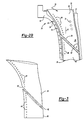
- FIG. 3 shows further detail of the impingement tubes 36 and 40.
- end walls 38 and 42 are generally planar, other shapes for the impingement tube portions that would achieve the volume flow characteristics described above, and/or the resistance to dirt migration would come within the scope of this invention.
- the inner and outer portions are formed as separate pieces.
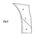
- Figure 4 shows an embodiment wherein the outer portion 202 and inner portion 204 of an impingement tube are formed as a single piece.
- a single wall 206 provides the characteristics as mentioned above.
- While the invention is disclosed in a vane, it would have potential application in other turbine components that receive both inner and outer cooling air flows. Examples may include burner liners, flame holders, turbine exhaust cases, etc.
Landscapes
- Engineering & Computer Science (AREA)
- Chemical & Material Sciences (AREA)
- Combustion & Propulsion (AREA)
- Mechanical Engineering (AREA)
- General Engineering & Computer Science (AREA)
- Turbine Rotor Nozzle Sealing (AREA)
- Structures Of Non-Positive Displacement Pumps (AREA)
Abstract
Description
- This invention relates to an impingement tube received within a turbine component, and in which the impingement tube has an inner and outer portion, with the outer portion being configured to minimize dirt blockage of impingement air at the leading edge. In one embodiment, the inner and outer portions are formed as separate pieces, and in another embodiment, the inner and outer portions are formed as a single piece.
- Turbine engines have a number of components. One type of component is a stationary vane. The vanes are in the path of hot air downstream of a combustor, and have a leading edge that faces the hot air. The vane is thus exposed to high temperatures and requires cooling. One method utilized to cool the vane, is to form the vane to have hollow areas, and place impingement tubes within the hollow areas. The impingement tubes have a number of holes for directing impingement air outwardly to points within the vane. Holes also extend through the wall of the vane in order to direct the impingement air onto an outer surface of the vane.
- This application relates to an impingement tube used within the hollow area of the vane that receives cooling air from both inner and outer vane cooling air supplies. One known way of supplying impingement cooling air from both inner and outer supplies is to use an impingement tube which includes an outer portion and an inner portion. Each of the inner and outer portions have an end wall roughly at an intermediate position within the vane, and with end walls both being generally parallel to an axis of rotation for the turbine. Outer cooling air is brought within the outer portion and inner cooling air is brought within the inner portion. The holes within the impingement tube portions and the vane are concentrated adjacent the leading edge of the vane.
- It has been found that the air from a radially outer source carries more dirt than air from a radially inner source. The holes in the impingement tube and vane are relatively small, and are sometimes clogged by dirt within the impingement airflow. When this dirt clogs the holes near the leading edge, less air than may be desirable is directed to the leading edge.
- In a disclosed embodiment of this invention, a vane receives an impingement tube including an inner and an outer portion. In one embodiment, end walls of the inner and outer portions are formed to be non-parallel relative to the axis of rotation of the turbine. In particular, an end wall within the outer portion is positioned such that the outer portion covers less of a leading edge of the vane than it covers at the aft end spaced towards the trailing edge. In the disclosed embodiment, the end wall of the outer portion is generally planar, and angled radially inwardly from the leading edge moving toward trailing edge. In this manner, the outer portion has more surface area adjacent the aft end than it does at the leading edge. Thus, the dirtier outer impingement air flows in greater volumes to the aft end than it does to the leading edge.
- The inner portion is formed in an opposite manner, with its end wall also moving radially inwardly from the leading edge toward the trailing edge. However, with the inner portion, the effect of this angled end wall is to increase the volume of air directed from the inner impingement air source to the leading edge relative to the volume of air directed to the aft end.
- Not only does this shape reduce the volume of outer impingement airflow being directed to the leading edge relative to the aft end, but there are also mechanical means and resultant flow dynamics that reduce the amount of dirt reaching the leading edge of the vane. In particular, when air from the outer impingement air source enters the outer portion, there is momentum which causes dirt to be directed along the angled end wall away from the leading edge and toward the aft end of the outer impingement tube. With the prior art construction, dirt was not directed toward the aft end and was as likely to initially reside at the leading edge as it was the aft end. Also, with the prior art construction, dirt initially at the aft end can migrate back toward the leading edge. However, with the present invention, the angled end wall "pins" the dirt at the aft end. This is due to a pressure loading from the wedge shape. Purge holes at the bottom of the wedge, in conjunction with the suppressed static pressure inherent to the decrease in area heading toward the aft edge, create an increased dynamic pressure load that resists movement of the dirt from the aft end toward the leading edge in the outer portion. Also, the angled end wall creates a wedge shape which acts as a mechanical means of trapping the dirt. The angled end wall first directs dirt to the aft end of the outer impingement tube where once there its is pinned both mechanically and from the resulting flow dynamics from movement toward the leading edge.
- The dirt thus tends to become trapped or to exit the outer portion adjacent the aft end. The dirt that exits the outer portion adjacent the trailing edge may then leave the vane altogether through film holes in the outer surface of the vane adjacent the aft end. In essence, the wedge shape creates a trap that either captures dirt permanently or allows the dirt to exit the vane adjacent the aft end where it is least likely of plugging the leading edge of the vane.
- While the invention is disclosed with generally planar end walls angled in this fashion, other shapes for the outer portion and/or the inner portion could be utilized, as long as they achieve the goal of reducing the airflow from the outer impingement air source to the leading edge of the vane.
- In a first embodiment, the inner and outer portions are formed as separate pieces. In a second embodiment, the inner and outer portions are formed as a single piece.
- The present invention thus reduces the likelihood of the dirt within the outer airflow from reducing the impingement airflow to the leading edge of the vane.
- These and other features of the present invention can be best understood from the following specification and drawings, the following of which is a brief description.
-
- Figure 1 is a view of a portion of a turbine engine.
- Figure 2A shows a vane incorporating the present invention.
- Figure 2B is a cross-sectional view through a portion of a vane.
- Figure 3 is a perspective view of an inventive impingement tube set.
- Figure 4 shows a second embodiment impingement tube.
- A
gas turbine engine 20 is illustrated in Figure 1. As is known,rotor blades 22 rotate about a central axis, and receive air from an upstream combustor. A plurality ofstationary vanes 24 are positioned adjacent therotor blades 22. As is known, thevanes 24 are exposed to very hot air, and thus cooling air is directed into thevanes 24. As shown, there is a radiallyinner source 26 for cooling air and a radiallyouter source 28 for cooling air. The air exits thevanes 24 such as throughfilm cooling holes 25 found at the leading edge. Other holes are found across the vane, but are not illustrated for simplicity. It has been determined that the radiallyouter source 28 directs air that carries more dirt into thevane 24 compared to the radiallyinner source 26. A radial line R, which will be used as a reference below, could be described which is generally perpendicular to the rotational axis of therotor blades 22. - Figure 2A shows
vane 24, having a leadingedge 34, arib 32 spaced toward atrailing edge 21, as well as inner andouter platforms hollow area 19 will receive one impingement tube, and another impingement tube is received in another hollow area and includes anouter portion 36 and aninner portion 40 adjacent the leadingedge 34. As shown, theouter portion 36 has anend 38 and theinner portion 40 has anend 42. - As shown in Figure 2B,
vane 24 includes anouter wall 30 at a leadingedge 34. As known, the leadingedge 34 is exposed to the hottest temperatures, as it directly faces into the flow downstream of the combustor. - The cooling air from the
outer air source 28 is directed into the outerimpingement tube portion 36 having anend wall 38. The innerimpingement tube portion 40 receives air from theinner air source 26, and has anend wall 42. As can be appreciated from Figures 2A and 2B, theend walls rotor blade 22. In the prior art, theend walls rotor blade 22. - The
impingement tube portions holes 44 are found across the impingementair tube portions edge 34 in this application. The impingement air tube portions have a greater concentration ofholes 44 adjacent the leading edge, as it is desirable to direct the most cooling air to the leading edge. However, it should be understood that other holes would be found spaced away from the leading edge of theimpingement tube portions - As mentioned above, dirt D is found to a greater extent in the
outer airflow source 28 than in theinner airflow source 26. In the past, this dirt has plugged holes such asholes leading edge 34. - Momentum from the
outer airflow 28 will carry the heavier dirt particles D into thewedge 46 created between theaft end 35 and theend wall 38 and further away from the leading of the outer impingement tube holes 44 and leading edge holes 25. In the prior art, with the end wall being parallel to the rotational axis of the turbine, the dirt particles were not directed away from the leading edge or restrained from migrating back toward the leading edge and eventually plugging theholes edge 34. - The present invention addresses this concern in three ways. First, since the
end wall 38 is angled from the leading edge inward toward theaft end 35, there is a dynamic pressure load on the dirt particles D resisting migration toward the leading edge. Second, due to the wedge shape created betweenaft end 35 andend wall 38 dirt will become trapped within the deep tight corner of the impingement tube or exit theaft end 35 instead of migrating toward the leading edge and pluggingholes impingement tube portion 36 is such that there is less flow cross-sectional area adjacent the leading edge than there is adjacent the aft end edge. As can be appreciated from Figure 2, the opposite would be true of the radially innerimpingement tube portion 40. Thus, the radiallyinner source 26 provides a greater volume of cooling air to the leadingedge 34 than it does to thesecond end 35, while the radiallyouter source 28 supplies more impingement cooling air to theaft end 35 than it does the leadingedge 34. These factors in combination, reduce the amount of dirt likely to reach theholes vane 24 and the outerimpingement tube portion 36. - An angle A measured between the
end wall 38 and theaft end 35 of the outerimpingement tube portion 36 is preferably between 20 and 60°. In one embodiment, the angle is 36°. It is important that the angle is small enough to collect the dirt, but not large enough to affect the cooling airflow through the impingement tube. The angle of theinner portion end 42 wall is parallel to endwall 38. - Thus, the problem discussed above is addressed. There is a greater reliability of impingement air being directed to the leading
edge 34 of thevane 24. - Figure 3 shows further detail of the
impingement tubes - While in the disclosed embodiment the
end walls - In the above embodiments, the inner and outer portions are formed as separate pieces. Figure 4 shows an embodiment wherein the
outer portion 202 andinner portion 204 of an impingement tube are formed as a single piece. Asingle wall 206 provides the characteristics as mentioned above. - While the invention is disclosed in a vane, it would have potential application in other turbine components that receive both inner and outer cooling air flows. Examples may include burner liners, flame holders, turbine exhaust cases, etc.
- Although a preferred embodiment of this invention has been disclosed, a worker of ordinary skill in this art would recognize that certain modifications would come within the scope of this invention. For that reason, the following claims should be studied to determine the true scope and content of this invention.
Claims (13)
- A gas turbine engine (20) comprising:at least one rotor (22) for rotating about a central axis;at least one vane (24), said vane having a leading edge (34) and a trailing edge (21), said vane (24) receiving an impingement tube adjacent said leading edge (34), said impingement tube having a leading edge and an aft end (35) spaced from said leading edge and towards said trailing edge of said vane;an outer air source (28) for directing air from a radially outer location into said impingement tube, and an inner air source (26) for directing air from a radially inner location into said impingement tube; andsaid impingement tube including a radially outer portion (36) and a radially inner portion (40), with said radially inner portion (40) receiving air from said inner air source (26) and said radially outer portion (36) receiving air from said outer air source (28), said radially inner and outer portions (40,36) having impingement air holes (44) for directing impingement air to a position adjacent said leading edge (34) of said vane, and at least said radially outer portion (36) being configured to direct a greater volume of impingement air toward said aft end (35) of said vane (24) than the volume directed toward said leading edge (34).
- A turbine component comprising:a body having a leading edge (34) and a trailing edge (21), said body having a radially outer edge and a radially inner edge;an impingement tube receiving within said body and including a radially outer portion (36) and a radially inner portion (40), with said radially inner portion (40) for receiving air from a radially inner source and said radially outer portion (36) for receiving air from a radially outer source, said radially inner and outer portions (40,36) having impingement air holes (44) for directing impingement air to a position adjacent said leading edge (34) of said body, and at least said radially outer portion (36) being configured to direct a greater volume of impingement air to an aft end (35), spaced from said leading edge (34) and in a direction toward said trailing edge of said body, than is directed toward said leading edge (34).
- The turbine component as set forth in claim 2, wherein said body is a vane airfoil (24).
- The turbine engine or turbine component as set forth in claim 1 or 3, wherein said radially inner portion (40) directs a greater volume of impingement airflow toward said leading edge (34) of said vane (24) than it does toward said aft end (35).
- The turbine engine or turbine component as set forth in claim 4, wherein both said radially outer and radially inner portions (36,40) have end walls (38,42).
- The turbine engine or turbine component as set forth in claim 5, wherein said end wall (38) of said radially outer portion (36) is angled from said leading edge (34) toward said aft end (35) in a radially inner direction such that said leading edge of said radially outer portion (36) is shorter than said aft end (35).
- The turbine engine or turbine component as set forth in claim 6, wherein said end wall of said radially inner portion is angled from said leading edge (34) toward said aft end (35) in a radially inner direction such that said leading edge of said radially inner portion (40) is longer than said aft end (35).
- The turbine engine or turbine component as set forth in claim 7, wherein said end walls (38,42) of said radially outer portion (36) and said radially inner portion (40) are generally parallel to each other.
- The turbine engine or turbine component as set forth in claim 6, 7 or 8,
wherein an angle (A) between said end wall (38) and said aft end (35) of said radially outer portion (36) is between 20° and 60°. - The turbine engine or turbine component as set forth in any preceding claim,
wherein said radially outer portion (36) and said radially inner portion (40) are formed as two separate pieces. - The turbine engine or turbine component as set forth in any of claims 1 to 10, wherein said radially outer portion (202) and said radially inner portion (204) are formed as a single piece.
- A method of reducing dirt flow toward a leading edge (34) of a hollow airfoil (24) comprising the steps of:(1) providing a airfoil, and an impingement tube within said airfoil, with a radially outer impingement tube portion (36) and a radially inner impingement tube portion (40), directing a radially outer air source (28) into said radially outer impingement tube portion (36), and directing a radially inner source (26) into said radially inner impingement tube portion (40); and(2) shaping said outer impingement tube portion (36) such that it minimizes dirt moving toward a leading edge of said radially outer impingement tube portion (36).
- The method as set forth in claim 12, wherein an end wall (38) of said radially outer impingement tube portion (36) is shaped such that a greater volume of airflow is directed from said radially outer source (28) to an aft end (35) of said radially outer impingement tube portion (36) that is spaced toward a trailing edge (21) of said air foil, than is directed to said leading edge (34).
Applications Claiming Priority (1)
| Application Number | Priority Date | Filing Date | Title |
|---|---|---|---|
| US11/018,629 US7431559B2 (en) | 2004-12-21 | 2004-12-21 | Dirt separation for impingement cooled turbine components |
Publications (3)
| Publication Number | Publication Date |
|---|---|
| EP1674660A2 true EP1674660A2 (en) | 2006-06-28 |
| EP1674660A3 EP1674660A3 (en) | 2009-09-09 |
| EP1674660B1 EP1674660B1 (en) | 2011-06-15 |
Family
ID=36087682
Family Applications (1)
| Application Number | Title | Priority Date | Filing Date |
|---|---|---|---|
| EP05256498A Expired - Lifetime EP1674660B1 (en) | 2004-12-21 | 2005-10-20 | Impingement cooled turbine components with dirt separation |
Country Status (7)
| Country | Link |
|---|---|
| US (1) | US7431559B2 (en) |
| EP (1) | EP1674660B1 (en) |
| JP (1) | JP2006177340A (en) |
| KR (1) | KR20060071301A (en) |
| CN (1) | CN100585130C (en) |
| SG (1) | SG123662A1 (en) |
| TW (1) | TWI279487B (en) |
Cited By (6)
| Publication number | Priority date | Publication date | Assignee | Title |
|---|---|---|---|---|
| EP2418355A1 (en) * | 2010-08-13 | 2012-02-15 | Siemens Aktiengesellschaft | Gas turbine vane |
| EP2706195A1 (en) * | 2012-09-05 | 2014-03-12 | Siemens Aktiengesellschaft | Impingement tube for gas turbine vane with a partition wall |
| EP1908921B1 (en) | 2006-09-28 | 2015-12-30 | United Technologies Corporation | Method of impingement cooling a turbine airfoil and corresponding turbine airfoil |
| US9238968B2 (en) | 2011-02-28 | 2016-01-19 | Rolls-Royce Plc | Vane |
| EP3650654A1 (en) * | 2018-11-09 | 2020-05-13 | United Technologies Corporation | Airfoil, corresponding gas turbine engine and method for assembling |
| FR3094743A1 (en) * | 2019-04-03 | 2020-10-09 | Safran Aircraft Engines | Improved blade for turbomachine |
Families Citing this family (17)
| Publication number | Priority date | Publication date | Assignee | Title |
|---|---|---|---|---|
| US10286407B2 (en) | 2007-11-29 | 2019-05-14 | General Electric Company | Inertial separator |
| US8142153B1 (en) * | 2009-06-22 | 2012-03-27 | Florida Turbine Technologies, Inc | Turbine vane with dirt separator |
| JP5683336B2 (en) * | 2011-03-14 | 2015-03-11 | 三菱重工業株式会社 | gas turbine |
| EP2921650B1 (en) | 2014-03-20 | 2017-10-04 | Ansaldo Energia Switzerland AG | Turbine vane with cooled fillet |
| CA2949547A1 (en) | 2014-05-29 | 2016-02-18 | General Electric Company | Turbine engine and particle separators therefore |
| US10975731B2 (en) | 2014-05-29 | 2021-04-13 | General Electric Company | Turbine engine, components, and methods of cooling same |
| US9915176B2 (en) | 2014-05-29 | 2018-03-13 | General Electric Company | Shroud assembly for turbine engine |
| US11033845B2 (en) | 2014-05-29 | 2021-06-15 | General Electric Company | Turbine engine and particle separators therefore |
| US10167725B2 (en) | 2014-10-31 | 2019-01-01 | General Electric Company | Engine component for a turbine engine |
| US10036319B2 (en) | 2014-10-31 | 2018-07-31 | General Electric Company | Separator assembly for a gas turbine engine |
| JP5908054B2 (en) * | 2014-11-25 | 2016-04-26 | 三菱重工業株式会社 | gas turbine |
| EP3032034B1 (en) * | 2014-12-12 | 2019-11-27 | United Technologies Corporation | Baffle insert, vane with a baffle insert, and corresponding method of manufacturing a vane |
| US9988936B2 (en) | 2015-10-15 | 2018-06-05 | General Electric Company | Shroud assembly for a gas turbine engine |
| US10174620B2 (en) | 2015-10-15 | 2019-01-08 | General Electric Company | Turbine blade |
| US10428664B2 (en) | 2015-10-15 | 2019-10-01 | General Electric Company | Nozzle for a gas turbine engine |
| US10704425B2 (en) | 2016-07-14 | 2020-07-07 | General Electric Company | Assembly for a gas turbine engine |
| US20180328187A1 (en) * | 2017-05-09 | 2018-11-15 | General Electric Company | Turbine engine with an airfoil and insert |
Citations (1)
| Publication number | Priority date | Publication date | Assignee | Title |
|---|---|---|---|---|
| US4798515A (en) | 1986-05-19 | 1989-01-17 | The United States Of America As Represented By The Secretary Of The Air Force | Variable nozzle area turbine vane cooling |
Family Cites Families (13)
| Publication number | Priority date | Publication date | Assignee | Title |
|---|---|---|---|---|
| US3574481A (en) * | 1968-05-09 | 1971-04-13 | James A Pyne Jr | Variable area cooled airfoil construction for gas turbines |
| GB1587401A (en) * | 1973-11-15 | 1981-04-01 | Rolls Royce | Hollow cooled vane for a gas turbine engine |
| GB1467483A (en) | 1974-02-19 | 1977-03-16 | Rolls Royce | Cooled vane for a gas turbine engine |
| US4685942A (en) * | 1982-12-27 | 1987-08-11 | General Electric Company | Axial flow inlet particle separator |
| US4962640A (en) | 1989-02-06 | 1990-10-16 | Westinghouse Electric Corp. | Apparatus and method for cooling a gas turbine vane |
| US5405242A (en) * | 1990-07-09 | 1995-04-11 | United Technologies Corporation | Cooled vane |
| JP3794868B2 (en) | 1999-06-15 | 2006-07-12 | 三菱重工業株式会社 | Gas turbine stationary blade |
| US6543993B2 (en) * | 2000-12-28 | 2003-04-08 | General Electric Company | Apparatus and methods for localized cooling of gas turbine nozzle walls |
| US6698180B2 (en) * | 2001-08-01 | 2004-03-02 | Rolls-Royce Corporation | Particle separator for a turbine engine |
| US6554563B2 (en) * | 2001-08-13 | 2003-04-29 | General Electric Company | Tangential flow baffle |
| US6652220B2 (en) * | 2001-11-15 | 2003-11-25 | General Electric Company | Methods and apparatus for cooling gas turbine nozzles |
| GB2386926A (en) * | 2002-03-27 | 2003-10-01 | Alstom | Two part impingement tube for a turbine blade or vane |
| US6951444B2 (en) | 2002-10-22 | 2005-10-04 | Siemens Aktiengesselschaft | Turbine and a turbine vane for a turbine |
-
2004
- 2004-12-21 US US11/018,629 patent/US7431559B2/en not_active Expired - Lifetime
-
2005
- 2005-09-05 TW TW094130240A patent/TWI279487B/en not_active IP Right Cessation
- 2005-09-19 SG SG200506001A patent/SG123662A1/en unknown
- 2005-10-05 JP JP2005291835A patent/JP2006177340A/en active Pending
- 2005-10-07 KR KR1020050094294A patent/KR20060071301A/en not_active Abandoned
- 2005-10-20 EP EP05256498A patent/EP1674660B1/en not_active Expired - Lifetime
- 2005-10-20 CN CN200510108695A patent/CN100585130C/en not_active Expired - Fee Related
Patent Citations (1)
| Publication number | Priority date | Publication date | Assignee | Title |
|---|---|---|---|---|
| US4798515A (en) | 1986-05-19 | 1989-01-17 | The United States Of America As Represented By The Secretary Of The Air Force | Variable nozzle area turbine vane cooling |
Cited By (10)
| Publication number | Priority date | Publication date | Assignee | Title |
|---|---|---|---|---|
| EP1908921B1 (en) | 2006-09-28 | 2015-12-30 | United Technologies Corporation | Method of impingement cooling a turbine airfoil and corresponding turbine airfoil |
| EP2418355A1 (en) * | 2010-08-13 | 2012-02-15 | Siemens Aktiengesellschaft | Gas turbine vane |
| WO2012019975A1 (en) | 2010-08-13 | 2012-02-16 | Siemens Aktiengesellschaft | Gas turbine vane |
| US9238968B2 (en) | 2011-02-28 | 2016-01-19 | Rolls-Royce Plc | Vane |
| EP2706195A1 (en) * | 2012-09-05 | 2014-03-12 | Siemens Aktiengesellschaft | Impingement tube for gas turbine vane with a partition wall |
| WO2014037227A1 (en) * | 2012-09-05 | 2014-03-13 | Siemens Aktiengesellschaft | Impingement tube for gas turbine vane with a partition wall |
| EP3650654A1 (en) * | 2018-11-09 | 2020-05-13 | United Technologies Corporation | Airfoil, corresponding gas turbine engine and method for assembling |
| US11661850B2 (en) | 2018-11-09 | 2023-05-30 | Raytheon Technologies Corporation | Airfoil with convex sides and multi-piece baffle |
| FR3094743A1 (en) * | 2019-04-03 | 2020-10-09 | Safran Aircraft Engines | Improved blade for turbomachine |
| US11795828B2 (en) | 2019-04-03 | 2023-10-24 | Safran Aircraft Engines | Blade for a turbine engine, associated turbine engine distributor and turbine engine |
Also Published As
| Publication number | Publication date |
|---|---|
| CN100585130C (en) | 2010-01-27 |
| SG123662A1 (en) | 2006-07-26 |
| EP1674660A3 (en) | 2009-09-09 |
| KR20060071301A (en) | 2006-06-26 |
| TW200626791A (en) | 2006-08-01 |
| TWI279487B (en) | 2007-04-21 |
| CN1793616A (en) | 2006-06-28 |
| US7431559B2 (en) | 2008-10-07 |
| US20060133923A1 (en) | 2006-06-22 |
| EP1674660B1 (en) | 2011-06-15 |
| JP2006177340A (en) | 2006-07-06 |
Similar Documents
| Publication | Publication Date | Title |
|---|---|---|
| EP1674660B1 (en) | Impingement cooled turbine components with dirt separation | |
| US6554569B2 (en) | Compressor outlet guide vane and diffuser assembly | |
| JP5289694B2 (en) | Turbine airfoil curved squealer tip with tip shelf | |
| CN107013248B (en) | Method and system for improving turbine blade performance | |
| JP6266231B2 (en) | Cooling structure at the tip of turbine rotor blade | |
| CN103422908B (en) | Cooling structure in the end of turbine rotor blade | |
| US7712316B2 (en) | Turbine blade with reverse cooling air film hole direction | |
| JP6461382B2 (en) | Turbine blade with shroud | |
| KR20100076891A (en) | Turbine rotor blade tips that discourage cross-flow | |
| US10253634B2 (en) | Gas turbine engine airfoil trailing edge suction side cooling | |
| JP5150059B2 (en) | Turbine airfoil with a tapered trailing edge land | |
| US9777582B2 (en) | Tip leakage flow directionality control | |
| US20140030101A1 (en) | Turbine bucket with squealer tip | |
| CN106968722B (en) | Turbine airfoil trailing edge cooling passage | |
| CN110005473A (en) | Two-part cooling duct for airfoil | |
| CN105074132B (en) | Platform cooling device on root side of turbomachine part cooling platform and turbomachine part | |
| US10933481B2 (en) | Method of forming cooling passage for turbine component with cap element | |
| US11965429B1 (en) | Turbomachine component with film-cooling hole with hood extending from wall outer surface | |
| JP2021501285A (en) | Turbine blade with tip trench | |
| US20160146044A1 (en) | Internally cooled turbine platform | |
| TWI890752B (en) | Blade comprising tip squealer configurations and turbine engine including the blade | |
| US10975702B2 (en) | Platform cooling arrangement for a gas turbine engine |
Legal Events
| Date | Code | Title | Description |
|---|---|---|---|
| PUAI | Public reference made under article 153(3) epc to a published international application that has entered the european phase |
Free format text: ORIGINAL CODE: 0009012 |
|
| AK | Designated contracting states |
Kind code of ref document: A2 Designated state(s): AT BE BG CH CY CZ DE DK EE ES FI FR GB GR HU IE IS IT LI LT LU LV MC NL PL PT RO SE SI SK TR |
|
| AX | Request for extension of the european patent |
Extension state: AL BA HR MK YU |
|
| PUAL | Search report despatched |
Free format text: ORIGINAL CODE: 0009013 |
|
| AK | Designated contracting states |
Kind code of ref document: A3 Designated state(s): AT BE BG CH CY CZ DE DK EE ES FI FR GB GR HU IE IS IT LI LT LU LV MC NL PL PT RO SE SI SK TR |
|
| AX | Request for extension of the european patent |
Extension state: AL BA HR MK YU |
|
| 17P | Request for examination filed |
Effective date: 20100120 |
|
| 17Q | First examination report despatched |
Effective date: 20100216 |
|
| AKX | Designation fees paid |
Designated state(s): DE GB |
|
| GRAP | Despatch of communication of intention to grant a patent |
Free format text: ORIGINAL CODE: EPIDOSNIGR1 |
|
| GRAS | Grant fee paid |
Free format text: ORIGINAL CODE: EPIDOSNIGR3 |
|
| GRAA | (expected) grant |
Free format text: ORIGINAL CODE: 0009210 |
|
| AK | Designated contracting states |
Kind code of ref document: B1 Designated state(s): DE GB |
|
| REG | Reference to a national code |
Ref country code: GB Ref legal event code: FG4D |
|
| REG | Reference to a national code |
Ref country code: DE Ref legal event code: R096 Ref document number: 602005028506 Country of ref document: DE Effective date: 20110728 |
|
| PLBE | No opposition filed within time limit |
Free format text: ORIGINAL CODE: 0009261 |
|
| STAA | Information on the status of an ep patent application or granted ep patent |
Free format text: STATUS: NO OPPOSITION FILED WITHIN TIME LIMIT |
|
| 26N | No opposition filed |
Effective date: 20120316 |
|
| REG | Reference to a national code |
Ref country code: DE Ref legal event code: R097 Ref document number: 602005028506 Country of ref document: DE Effective date: 20120316 |
|
| PGFP | Annual fee paid to national office [announced via postgrant information from national office to epo] |
Ref country code: DE Payment date: 20121017 Year of fee payment: 8 |
|
| PGFP | Annual fee paid to national office [announced via postgrant information from national office to epo] |
Ref country code: GB Payment date: 20121017 Year of fee payment: 8 |
|
| GBPC | Gb: european patent ceased through non-payment of renewal fee |
Effective date: 20131020 |
|
| PG25 | Lapsed in a contracting state [announced via postgrant information from national office to epo] |
Ref country code: GB Free format text: LAPSE BECAUSE OF NON-PAYMENT OF DUE FEES Effective date: 20131020 |
|
| REG | Reference to a national code |
Ref country code: DE Ref legal event code: R119 Ref document number: 602005028506 Country of ref document: DE Effective date: 20140501 |
|
| PG25 | Lapsed in a contracting state [announced via postgrant information from national office to epo] |
Ref country code: DE Free format text: LAPSE BECAUSE OF NON-PAYMENT OF DUE FEES Effective date: 20140501 |