EP1674541B1 - Adhesive joint for connecting components of transportation, particularly of aircrafts, as well as the process for the determination of a mechanical minimum stress and/or a mechanical strength of an adhesive joint - Google Patents
Adhesive joint for connecting components of transportation, particularly of aircrafts, as well as the process for the determination of a mechanical minimum stress and/or a mechanical strength of an adhesive joint Download PDFInfo
- Publication number
- EP1674541B1 EP1674541B1 EP05027966A EP05027966A EP1674541B1 EP 1674541 B1 EP1674541 B1 EP 1674541B1 EP 05027966 A EP05027966 A EP 05027966A EP 05027966 A EP05027966 A EP 05027966A EP 1674541 B1 EP1674541 B1 EP 1674541B1
- Authority
- EP
- European Patent Office
- Prior art keywords
- functional elements
- adhesive joint
- adhesive
- control signal
- mechanical
- Prior art date
- Legal status (The legal status is an assumption and is not a legal conclusion. Google has not performed a legal analysis and makes no representation as to the accuracy of the status listed.)
- Not-in-force
Links
- 239000000853 adhesive Substances 0.000 title claims abstract description 189
- 230000001070 adhesive effect Effects 0.000 title claims abstract description 189
- 238000000034 method Methods 0.000 title claims description 33
- 230000008569 process Effects 0.000 title description 5
- 239000000463 material Substances 0.000 claims abstract description 4
- 238000005304 joining Methods 0.000 claims abstract description 3
- 229910001285 shape-memory alloy Inorganic materials 0.000 claims description 8
- 239000000919 ceramic Substances 0.000 claims description 7
- 229920000642 polymer Polymers 0.000 claims description 5
- 239000007788 liquid Substances 0.000 claims description 4
- 239000004033 plastic Substances 0.000 claims description 4
- 229920003023 plastic Polymers 0.000 claims description 4
- 238000005259 measurement Methods 0.000 abstract description 19
- 238000012360 testing method Methods 0.000 description 26
- 239000002313 adhesive film Substances 0.000 description 15
- 230000001105 regulatory effect Effects 0.000 description 15
- 238000004519 manufacturing process Methods 0.000 description 8
- 235000011837 pasties Nutrition 0.000 description 5
- 238000009864 tensile test Methods 0.000 description 5
- 230000008878 coupling Effects 0.000 description 4
- 238000010168 coupling process Methods 0.000 description 4
- 238000005859 coupling reaction Methods 0.000 description 4
- 239000003822 epoxy resin Substances 0.000 description 4
- 238000011156 evaluation Methods 0.000 description 4
- 229920000647 polyepoxide Polymers 0.000 description 4
- 230000001953 sensory effect Effects 0.000 description 4
- 230000001066 destructive effect Effects 0.000 description 3
- 238000001514 detection method Methods 0.000 description 3
- 238000010586 diagram Methods 0.000 description 3
- 101100074336 Xenopus laevis ripply2.1 gene Proteins 0.000 description 2
- 230000009471 action Effects 0.000 description 2
- 230000004913 activation Effects 0.000 description 2
- 230000008859 change Effects 0.000 description 2
- 230000006378 damage Effects 0.000 description 2
- 238000009658 destructive testing Methods 0.000 description 2
- 230000000694 effects Effects 0.000 description 2
- 230000005284 excitation Effects 0.000 description 2
- 239000000835 fiber Substances 0.000 description 2
- 239000010410 layer Substances 0.000 description 2
- 239000011159 matrix material Substances 0.000 description 2
- 239000002184 metal Substances 0.000 description 2
- 239000002985 plastic film Substances 0.000 description 2
- 229920006255 plastic film Polymers 0.000 description 2
- 230000001681 protective effect Effects 0.000 description 2
- 229920002430 Fibre-reinforced plastic Polymers 0.000 description 1
- 230000006978 adaptation Effects 0.000 description 1
- 239000000654 additive Substances 0.000 description 1
- 238000004026 adhesive bonding Methods 0.000 description 1
- 239000012790 adhesive layer Substances 0.000 description 1
- 239000002390 adhesive tape Substances 0.000 description 1
- 238000013459 approach Methods 0.000 description 1
- 238000005452 bending Methods 0.000 description 1
- 229910010293 ceramic material Inorganic materials 0.000 description 1
- 239000004020 conductor Substances 0.000 description 1
- 239000013078 crystal Substances 0.000 description 1
- 230000006735 deficit Effects 0.000 description 1
- 230000032798 delamination Effects 0.000 description 1
- 238000013461 design Methods 0.000 description 1
- 230000005684 electric field Effects 0.000 description 1
- 239000011151 fibre-reinforced plastic Substances 0.000 description 1
- 239000000945 filler Substances 0.000 description 1
- 230000006870 function Effects 0.000 description 1
- LNEPOXFFQSENCJ-UHFFFAOYSA-N haloperidol Chemical compound C1CC(O)(C=2C=CC(Cl)=CC=2)CCN1CCCC(=O)C1=CC=C(F)C=C1 LNEPOXFFQSENCJ-UHFFFAOYSA-N 0.000 description 1
- 238000010348 incorporation Methods 0.000 description 1
- 230000010354 integration Effects 0.000 description 1
- 238000004556 laser interferometry Methods 0.000 description 1
- 230000003278 mimic effect Effects 0.000 description 1
- 238000012544 monitoring process Methods 0.000 description 1
- 239000002245 particle Substances 0.000 description 1
- 238000002360 preparation method Methods 0.000 description 1
- 238000000275 quality assurance Methods 0.000 description 1
- 230000002787 reinforcement Effects 0.000 description 1
- 229920005989 resin Polymers 0.000 description 1
- 239000011347 resin Substances 0.000 description 1
- 238000012552 review Methods 0.000 description 1
- 238000010998 test method Methods 0.000 description 1
- 238000012876 topography Methods 0.000 description 1
- 238000002604 ultrasonography Methods 0.000 description 1
Images


Classifications
-
- F—MECHANICAL ENGINEERING; LIGHTING; HEATING; WEAPONS; BLASTING
- F16—ENGINEERING ELEMENTS AND UNITS; GENERAL MEASURES FOR PRODUCING AND MAINTAINING EFFECTIVE FUNCTIONING OF MACHINES OR INSTALLATIONS; THERMAL INSULATION IN GENERAL
- F16B—DEVICES FOR FASTENING OR SECURING CONSTRUCTIONAL ELEMENTS OR MACHINE PARTS TOGETHER, e.g. NAILS, BOLTS, CIRCLIPS, CLAMPS, CLIPS OR WEDGES; JOINTS OR JOINTING
- F16B11/00—Connecting constructional elements or machine parts by sticking or pressing them together, e.g. cold pressure welding
- F16B11/006—Connecting constructional elements or machine parts by sticking or pressing them together, e.g. cold pressure welding by gluing
-
- G—PHYSICS
- G01—MEASURING; TESTING
- G01L—MEASURING FORCE, STRESS, TORQUE, WORK, MECHANICAL POWER, MECHANICAL EFFICIENCY, OR FLUID PRESSURE
- G01L1/00—Measuring force or stress, in general
- G01L1/16—Measuring force or stress, in general using properties of piezoelectric devices
-
- Y—GENERAL TAGGING OF NEW TECHNOLOGICAL DEVELOPMENTS; GENERAL TAGGING OF CROSS-SECTIONAL TECHNOLOGIES SPANNING OVER SEVERAL SECTIONS OF THE IPC; TECHNICAL SUBJECTS COVERED BY FORMER USPC CROSS-REFERENCE ART COLLECTIONS [XRACs] AND DIGESTS
- Y10—TECHNICAL SUBJECTS COVERED BY FORMER USPC
- Y10T—TECHNICAL SUBJECTS COVERED BY FORMER US CLASSIFICATION
- Y10T403/00—Joints and connections
- Y10T403/20—Joints and connections with indicator or inspection means
Definitions
- the invention relates to an adhesive joint for connecting components of vehicles, in particular of aircraft, wherein the adhesive bond is formed with an adhesive.
- the invention relates to a method for determining a minimum mechanical load capacity and / or a mechanical strength of an adhesive bond for connecting components of vehicles, in particular aircraft, wherein in the adhesive bond formed with an adhesive joint more functional elements with actuator and / or sensory properties are integrated.
- the actual mechanical strength of adhesive joints between components can be tested, for example by mechanical tensile tests.
- the force acting on the components connected by means of the adhesive bond is increased by means of a measuring and testing device until the adhesive bond fails mechanically, so that the components can no longer be used.
- This procedure can be used advantageously in particular for determining and determining suitable basic process parameters, such as, for example, pressure, temperature and their time of action, in the production of adhesive bonds between components.
- this approach is also suitable for a random check of the maximum mechanical strength of adhesive bonds, which may result in the problem of lack of representation in relation to the total number of adhesive bonds produced.
- the usually very expensive destroyed components are then no longer for further assembly or the suitable for further operation, so that this destructive testing method is unsuitable for the continuous quality assurance of the current production.
- test methods such as load tests
- two components connected by the adhesive connection are clamped in a complex measuring and testing device, wherein the force acting on the adhesive bond force is increased by the measuring and testing device only so far that within the adhesive bond predetermined mechanical tension sets that excludes a failure of the adhesive bond under all conceivable subsequent operating conditions with a sufficiently high probability.
- WO 87/02745 discloses an overlapping adhesive joint having mutually overlapping first and second parts and an adhesive layer therebetween.
- the object of the invention is to provide an adhesive bond, the mechanical minimum strength and / or mechanical strength can be checked in a simple manner after their preparation, without elaborate testing and measuring devices for performing strength and / or resilience tests, directly with the adhesive bond itself , Furthermore, it is an object of the invention to detect mechanical load conditions directly in the adhesive bond.
- the adhesive has a plurality of functional elements with actuatory and / or sensory properties, in particular in order to enable a mechanical minimum load capacity of the adhesive bond and / or the detection of a mechanical load condition in the adhesive bond, is a simple and immediate verifiability of the mechanical strength of connected by means of the adhesive bond components according to the invention by the adhesive bond itself possible.
- the review of the mechanical strength of the connected by means of the adhesive bond components of the invention is preferably carried out non-destructive.
- a strength test of the adhesive bond is possible by means of the functional elements.
- mechanical stress states in the adhesive bond can be detected by means of the functional elements.
- a control signal in a mechanical stress within the adhesive bond convertible to determine a mechanical load capacity of the adhesive bond and / or by means of the functional elements is a mechanical stress in the adhesive bond in a measurement signal convertible to to detect a mechanical load condition in the adhesive joint.
- contact elements are arranged in the region of the functional elements for the supply and / or discharge of the control signal and / or the measurement signal.
- a further advantageous embodiment provides that the control signal and / or the measurement signal can be transmitted without contact.
- the control signal and / or the measuring signal can be transmitted without contact.
- a further advantageous embodiment of the adhesive connection according to the invention provides that the control signal is an electrical voltage and / or an electric current.
- the control signal in the control and regulating device can be generated and controlled in a simple manner, at least partially automatically.
- a further advantageous embodiment of the adhesive connection according to the invention provides that the measuring signal is an electrical voltage and / or an electric current. As a result, a simple and at least semi-automatic readability of the measurement signal in the control and regulating device is given.
- control signal can be generated in a control and regulating device and / or the measuring signal can be fed to the control and regulating device.
- the mechanical minimum load capacity and / or the detection of a mechanical load condition in the adhesive connection can be carried out at least partially automatically.
- the adhesive is formed with a sheet, in particular an adhesive strip.
- a sheet in particular an adhesive strip.
- the adhesive formed as an adhesive strip on one side and / or on both sides of a protective film.
- the adhesive in the form of an adhesive tape can be easily stored in a roll form.
- the adhesive is formed with a liquid plastic, in particular with a pasty liquid plastic.
- a pasty liquid plastic allows the application of the adhesive even in hard to reach places or in the range of adhesive bonds, which at least partially have a non-planar surface topography.
- a further embodiment of the adhesive bond according to the invention provides that the functional elements are in particular plate-shaped and / or strand-shaped.
- the functional elements are in particular plate-shaped and / or strand-shaped.
- the functional elements are formed with piezoelectric ceramics and / or with piezoelectric polymers.
- This embodiment allows both a sensory and an actuatoric operation of the functional elements.
- the functional elements are formed with so-called piezoelectric stacks, which provide large deformation paths even with relatively small electrical excitations and thus generate high mechanical stresses in the adhesive bond with a good electrical efficiency.
- the piezoelectric stacks consist in principle of a plurality of stacked piezoelectric ceramic plates or correspondingly arranged piezoelectric elements made of polymers.
- the functional elements may, unlike the platelet or the stack form, also be formed strand-like and in particular have the form of filaments or fibers which are integrated into the resin matrix of the adhesive bond.
- the functional elements are at least partially formed with shape memory alloys.
- shape memory alloys allows the production of functional elements that develop high mechanical forces even with relatively small electrical excitations or have deformation paths. A sensory operation of functional elements formed with shape memory alloys, however, is usually not possible.
- a material thickness of the adhesive can be adjusted by means of the functional elements. As a result, a defined distance of the assembled by means of the adhesive connection components is guaranteed. It is therefore no longer necessary to introduce additional additives into the adhesive to set a defined distance.
- the limit value of the control signal in this case preferably corresponds to a mechanical stress in the adhesive connection, which ensures a minimum mechanical load capacity of the adhesive bond. If necessary, the limit value of the control signal for carrying out strength tests may also correspond to a mechanical stress in the area of the mechanical strength of the adhesive bond.
- An advantageous embodiment of the method according to the invention provides that the control signal is increased until a limit is reached at which a mechanical stress prevails in the adhesive bond, which ensures a minimum mechanical load capacity of the adhesive bond. In this way, the minimum load capacity of the adhesive connection can be determined in a simple manner.
- a further advantageous embodiment of the method according to the invention provides that the control signal is increased until a limit value is reached at which a mechanical stress prevails in the adhesive bond, which exceeds a mechanical strength of the adhesive bond.
- the strength values of the adhesive bond can also be determined in a simple manner.
- the control signal is in this case increased until the adhesive bond fails mechanically.
- a further advantageous embodiment of the method according to the invention provides that a measurement signal is coupled out of the functional elements in order to determine the mechanical stress prevailing in the adhesive bond.
- a measurement signal is coupled out of the functional elements in order to determine the mechanical stress prevailing in the adhesive bond.
- FIG. 1 shows a section through two connected by means of the adhesive connection according to the invention components according to a first embodiment.
- a first component 1 is connected to a second component 2 by the adhesive connection 3 according to the invention.
- the components 1, 2 can each be made of metal and / or of a fiber-reinforced plastic material, in particular with a carbon-fiber-reinforced epoxy resin.
- the adhesive joint 3 is essentially formed with an adhesive 4, which is arranged between the first and the second component 1, 2.
- the adhesive 4 is formed in the embodiment shown with an adhesive film 5.
- the adhesive film 5 consists for example of a curable by suitable pressure and temperature epoxy resin.
- the adhesive film 5 if appropriate after the removal of protective and / or cover films, is placed in the region of a desired connection surface between the first component 1 and the second component 2. Subsequently, the components 1,2 are firmly bonded together by a suitable action of pressure, temperature and time.
- the adhesive film 5 transmits after the completion of the adhesive bond all occurring between the first component 1 and the second component 2 forces.
- so-called “piezoceramic stacks” are used as functional elements 6, 7, 8, which have a high mechanical deformation energy with minimal electrical energy input.
- the incorporation or integration of the functional elements 6,7,8 takes place, for example, in the production of the adhesive film 5.
- Functional elements 6, 7, 8 can also be formed in a strand-like manner, for example as a filament. Further geometric configurations are also possible.
- the functional elements 6, 7, 8 are preferably positioned in an approximately matrix-like manner within the adhesive film 5.
- any number of functional elements 6,7,8 may be integrated.
- the accuracy of a load measurement performed hereby can be increased in particular.
- the functional elements 6, 7, 8 formed, for example, with a piezoelectric ceramic material, defined mechanical stresses can be generated within the adhesive joint 3 for mechanical strength tests on the adhesive joint 3 (actuator operation).
- the generation of a mechanical stress takes place here in such a way that, for example, an electrical control voltage is applied to the functional elements 6, 7, 8 via contact elements which are not shown in greater detail in the representation of FIG.
- the functional elements 6,7,8 deform due to the piezoelectric effect corresponding to the height of the applied electrical control voltage and thereby produce a defined mechanical stress within the adhesive joint 3, which is used according to the invention for checking the mechanical strength of the adhesive joint 3.
- the functional elements 6, 7, 8 may be formed at least partially with piezoelectric polymers or the like.
- the main deformation direction of the functional elements 6, 7, 8 runs, for example, in the direction of the three black double arrows drawn in the region of the adhesive film 5, so that the adhesive joint 3 is essentially loaded with mechanical stresses in this spatial direction as a result of an expansion of the functional elements 6, 7, 8.
- the main deformation direction may deviate from this by functional elements 6, 7, 8 with another internal crystal structure or by another electrical activation, For example, be generated parallel to the surfaces of the components 1,2, to mimic a mechanical load on the adhesive bond 3 by shear forces. Deviating from this, for example, pressure forces can also be generated by a simple reversal of the control voltage by means of the functional elements 6, 7, 8 within the adhesive connection.
- the functional elements 6, 7, 8 also have connecting elements which are not shown in greater detail.
- Both the contact elements and the connection elements can be formed, for example, with metallized plastic films.
- the metallized plastic films are integrated into the adhesive film 5 and at the same time carry the functional elements 6, 7, 8.
- control voltage can also be coupled without contact into the functional elements 6, 7, 8.
- contact elements may be formed, for example, as antennas for receiving electromagnetic alternating fields.
- connection elements can then be omitted at least partially.
- a limit value for a control voltage must first be empirically determined, which corresponds to a required minimum load capacity of the adhesive joint 3, including a security surcharge. If the control voltage is applied in the amount of this limit value to the functional elements 6,7,8 and the adhesive bond 3 stops the internal mechanical stresses generated thereby, it can be assumed that the adhesive bond 3 will withstand all mechanical load cases occurring in practical operation ,
- a mechanical stress existing within the adhesive bond 3 according to the invention can also be detected by the functional elements 6, 7, 8 (sensor operation). Because each deformation of the functional elements 6,7,8 leads due to the piezoelectric effect also to a measuring voltage to the functional elements 6,7,8, which corresponds to the mechanical load condition or the mechanical stress, which consists in the interior of the adhesive joint 3. This deformation of the functional elements 6, 7, 8 can be generated either directly by forces acting on the outside or indirectly by functional elements 6, 7, 8 operated in the actuator mode. The measuring voltage can then be transmitted to the external control and regulating device via the contact elements. From the height of the measuring voltage can then be determined in the control and regulating device by means of suitable evaluation algorithms actually prevailing within the adhesive joint 3 mechanical stress.
- each functional element 6, 7, 8 can function both as an actuator for generating a mechanical stress by applying an electrical control voltage (actuator operation) or as a sensor for converting a mechanical stress into an electrical measuring voltage proportional thereto (sensor operation).
- the functional elements 6, 7, 8 can either be specialized in actuator operation or sensor operation or else there is a chronological sequence between the actuator operation and the sensor operation (multiplex operation).
- both the control voltage and the measurement voltage can be supplied or removed directly via the then partially electrically conductive components 1, 2.
- components 1, 2 made of carbon-fiber-reinforced epoxy resins
- existing metallic inserts for example lightning conductors, metal braids for dissipating electrical charges or the like, can also be used for signal routing.
- Another possibility is to at least partially doping the adhesive film 5, for example, with conductive particles. By applying an external magnetic alternating field, an electric field can then be generated in the adhesive film 5 in the region of the doping, which leads to the desired defined deformations of the functional elements 6, 7, 8 and thus to the intended mechanical stresses in the adhesive joint 3.
- the functional elements 6,7,8 at least partially formed as metallic shape memory alloys, for example, to achieve a higher efficiency in the actuator operation and thus higher mechanical stresses in the adhesive joint 3, a sensor operation is not possible in the rule.
- their temperature must be varied, which can be done for example by the coupling of an electric current, which leads to a corresponding increase in temperature.
- a controlled temperature change can also be effected without contact, for example by eddy currents inductively generated within the shape memory alloy or the like.
- the functional elements 6, 7, 8 also serve to ensure a minimum distance between the first and the second component 1, 2, by a precisely defined one Height of the resulting adhesive bond 3 between the components to achieve 1.2.
- the use of additional aggregates and fillers is thus at least partially unnecessary.
- FIG. 2 shows a sectional view through two components connected by means of the adhesive connection according to the invention in accordance with a second embodiment.
- a first component 9 is connected to a second component 10 by an adhesive connection 11.
- the adhesive 12 here is not an adhesive film but a pasty adhesive 13.
- the adhesive 13 may be, for example, a curable epoxy resin with or without a fiber reinforcement.
- the functional elements 14, 15, 16 formed, for example, with piezoelectric ceramics, in particular with piezo-ceramic stacks, are arranged.
- the spatial arrangement of the functional elements 14, 15, 16 essentially corresponds to the arrangement of the functional elements 6, 7, 8 in FIG. 1.
- the three black double arrows in the area of the adhesive 13 in turn symbolize the main deformation direction of the functional elements 14, 15, 16 when applied control voltage.
- FIG. 1 In contrast to the embodiment according to FIG.
- the functional elements 14, 15, 16 are connected to one another here by narrow webs 17, 18, so that when the pasty adhesive 13 is applied during the joining process, the strength of the matrix-like arrangement of the functional elements 14, 15, 16 is not significantly affected.
- the functional elements 14,15,16 reference is made to the statements made in the description of FIG. 1.
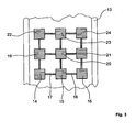
- FIG. 3 shows a section through the adhesive bond in accordance with the second embodiment along a section line AA in FIG. 2.
- the functional elements 14, 15, 16 are preferably arranged uniformly spaced from one another.
- the functional elements 14,15,16 are interconnected by the webs 17,18.
- the shown section of the matrix-like structure continues upward in the other functional elements 19-24, which are interconnected by in the illustration of FIG. 3 unspecified, corresponding to the webs 17,18 trained webs. Accordingly, the matrix-like arrangement of the functional elements also continues downwards. Notwithstanding the geometric arrangement shown, the functional elements 14,15,16 and 19-24 can be positioned in any conceivable manner and number to each other.
- the webs 17,18 may be part of a net-like structure, for example, in whose nodes then the functional elements are arranged.
- the webs 17,18 primarily secure the alignment of the functional elements 14-16 during the application of the paste 13 which is preferably pasty in this case to form the adhesive 12.
- the further webs correspondingly ensure the alignment of the functional elements 19-24.
- the webs may be at least partially electrically conductive to couple the control voltage and / or the measurement voltage to the functional elements 14-16,19-24.
- the webs can also be designed as antennas for receiving or for emitting electromagnetic waves.
- FIG. 4 schematically illustrates the sequence of the method according to the invention using the example of the adhesive joint 3 in accordance with FIG. 1.
- the method is correspondingly applicable to the adhesive bond 11 in accordance with FIG. 2.
- the ordinate of the diagram shown in FIG. 4 shows the mechanical stresses ⁇ prevailing in the adhesive bond 3 and the relative elongation s / s 0 of the adhesive bond 3, respectively.
- the horizontal dotted auxiliary line 25 corresponds to a minimum mechanical stress ⁇ m or a minimum strain s m / s o , which still has to be reliably tolerated by the adhesive joint 3 in order to obtain a sufficient mechanical failure under all possible real load conditions of the adhesive joint 3 high probability exclude.
- the drawn line with high line width 26 in this case represents an electrical control voltage U. applied to the functional elements 6, 7, 8 during the course of the process.
- the course of the control voltage U may have any deviating from the straight line 26, for example also non-linear time course. Instead of the control voltage and a control current can be impressed in the functional elements 6,7,8.
- the electrical control voltage U applied to the functional elements 6, 7, 8 is increased in steps or continuously by the control and regulating device until the mechanical stress ⁇ reaches a minimum stress ⁇ m within the adhesive 4, which is the horizontal, dotted auxiliary line 25 corresponds.
- This is generally the case when the control voltage U reaches a minimum electrical voltage Um, represented by the vertical, dotted auxiliary line 27.
- the amount of the minimum voltage Um to be applied to each of the functional elements 6, 7, 8, which still has to withstand the adhesive bond 3 in order to ensure a sufficient minimum mechanical load, is determined empirically.
- the measurement of the test stretch S Test / S 0 of the adhesive bond 3 can be carried out without contact by laser interferometry, for example.
- an electrical test voltage U test is applied to the adhesive joint 3, which sets in about the same relative test strain S test / S 0 as in the previous tensile test.
- the amount of this electrical test voltage U Test is measured and then represents the minimum voltage to be applied to the following strength measurements by means of the method according to the invention Um the electrical control voltage U, which must withstand an adhesive bond to be tested safely.
- the control and regulating device initially increases the control voltage U applied to the actuator elements 6, 8 operated, for example, until the evaluation of the measuring voltage of the then functionally operating functional element 7 results in a level of the electrical voltage corresponding to the minimum mechanical stress ⁇ m or ., a minimum elongation S m / S 0 corresponds, the adhesive connection 3 still has to withstand safe.
- the control and regulating device stops the voltage increase of the control voltage U to the actuatorally operated functional elements 6,8, so that the mechanical stress in the adhesive joint 3 does not increase further and damage or destruction of the adhesive joint 3 is omitted.
- Adhesive joint 3 the structural mechanical required minimum load capacity. Thus, it can be assumed that the tested adhesive joint 3 can withstand all occurring real mechanical load conditions in continuous operation safely.
- the connected by means of the inventively tested adhesive joint 3 components 1.2 can be safely used in production.
- the adhesive bond 3 already fails before reaching the minimum stress ⁇ m or before reaching the minimum electrical stress Um, for example due to overstretching, breakage, partial detachment or the like, which in the diagram of FIG. 4 is due to a bending and in the end region dotted curve 28 is shown, the adhesive joint 3 or the connected thereto components 1,2 must be discarded and can not be used after the test in production.
- adhesive bonds can be checked easily, quickly and directly, without the need to carry out complex tensile tests with complex measuring and testing devices, with regard to their mechanical strength and / or their mechanical strength. Furthermore, by means of the method according to the invention it is also possible to carry out load tests on adhesive joints in places which are difficult to access. Furthermore, the stress examinations on the adhesive joints can also be carried out without contact.
Abstract
Description
Die Erfindung betrifft eine Klebeverbindung zum Verbinden von Bauteilen von Verkehrsmitteln, insbesondere von Luftfahrzeugen, wobei die Klebeverbindung mit einem Klebemittel gebildet ist.The invention relates to an adhesive joint for connecting components of vehicles, in particular of aircraft, wherein the adhesive bond is formed with an adhesive.
Weiterhin betrifft die Erfindung ein Verfahren zur Ermittlung einer mechanischen Mindestbelastbarkeit und/oder einer mechanischen Festigkeit einer Klebeverbindung zur Verbindung von Bauteilen von Verkehrsmitteln, insbesondere von Luftfahrzeugen, wobei in der mit einem Klebemittel gebildeten Klebeverbindung mehrere Funktionselemente mit aktuatorischen und/oder sensorischen Eigenschaften integriert sind.Furthermore, the invention relates to a method for determining a minimum mechanical load capacity and / or a mechanical strength of an adhesive bond for connecting components of vehicles, in particular aircraft, wherein in the adhesive bond formed with an adhesive joint more functional elements with actuator and / or sensory properties are integrated.
Insbesondere im Flugzeugbau werden zunehmend Bauteile durch Verkleben verbunden, um einerseits den Produktionsprozess zu vereinfachen und anderseits im Verhältnis zu konventionellen Niet- und/oder Schweißverbindungen Gewicht einzusparen. Sehr aufwändig gestaltet sich bislang in diesem Zusammenhang die Überwachung der Einhaltung der Festigkeitswerte der zwischen den Bauteilen hergestellten Klebeverbindungen.In particular, in aircraft increasingly components are connected by gluing, on the one hand to simplify the production process and on the other hand to save weight in relation to conventional riveting and / or welded joints. In this context, the monitoring of compliance with the strength values of the adhesive bonds produced between the components has proven to be very complicated.
Nach Maßgabe des Standes der Technik kann die tatsächliche mechanische Belastbarkeit von Klebeverbindungen zwischen Bauteilen beispielsweise durch mechanische Zugversuche geprüft werden.In accordance with the prior art, the actual mechanical strength of adhesive joints between components can be tested, for example by mechanical tensile tests.
Bei einer derartigen zerstörenden Prüfung einer Klebeverbindung wird die auf die mittels der Klebeverbindung verbundenen Bauteile wirkende Kraft mittels einer Mess- und Prüfeinrichtung solange gesteigert, bis die Klebeverbindung mechanisch versagt, sodass die Bauteile nicht mehr verwendet werden können.
Diese Vorgehensweise ist insbesondere zur Ermittlung und Festlegung geeigneter grundlegender Verfahrensparameter, wie beispielsweise Druck, Temperatur und deren zeitliche Einwirkdauer, bei der Herstellung von Klebeverbindungen zwischen Bauteilen vorteilhaft einsetzbar. Darüber hinaus ist diese Vorgehensweise auch für eine stichprobenartige Überprüfung der maximalen mechanischen Belastbarkeit von Klebeverbindungen geeignet, wobei sich das Problem der mangelnden Repräsentanz in Bezug auf die Gesamtzahl der hergestellten Klebeverbindungen ergeben kann. Außerdem sind die in der Regel sehr teuren zerstörten Bauteile dann nicht mehr für die weitere Montage bzw. den weiteren Betrieb geeignet, sodass dieses zerstörende Prüfverfahren zur durchgängigen Qualitätssicherung der laufenden Produktion ungeeignet ist.In such a destructive testing of an adhesive bond, the force acting on the components connected by means of the adhesive bond is increased by means of a measuring and testing device until the adhesive bond fails mechanically, so that the components can no longer be used.
This procedure can be used advantageously in particular for determining and determining suitable basic process parameters, such as, for example, pressure, temperature and their time of action, in the production of adhesive bonds between components. In addition, this approach is also suitable for a random check of the maximum mechanical strength of adhesive bonds, which may result in the problem of lack of representation in relation to the total number of adhesive bonds produced. In addition, the usually very expensive destroyed components are then no longer for further assembly or the suitable for further operation, so that this destructive testing method is unsuitable for the continuous quality assurance of the current production.
Bei weiteren Prüfmethoden, wie zum Beispiel Belastungsversuchen, werden zwei durch die Klebeverbindung verbundene Bauteile in eine aufwändige Mess- und Prüfeinrichtung eingespannt, wobei die auf die Klebeverbindung wirkende Kraft durch die Mess- und Prüfeinrichtung nur so weit gesteigert wird, dass sich innerhalb der Klebeverbindung eine vorher festgelegte mechanische Spannung einstellt, die ein Versagen der Klebeverbindung unter allen denkbaren späteren Betriebszuständen mit einer ausreichend hohen Wahrscheinlichkeit ausschließt.
Die Durchführung von derartigen zerstörungsfreien Belastungsversuchen mit umfangreichen Mess- und Prüfeinrichtungen würde zwar die Sicherstellung der Qualität von geklebten Bauteilen während der laufenden Produktion beeinflussen, gestaltet sich aber in der Praxis zu aufwändig, weil beispielsweise für unterschiedliche Bauteile spezielle Adaptionsvorrichtungen bereitgehalten werden müssten, damit die Bauteile möglichst in nur einer Mess- und Prüfeinrichtung mit jeweils vergleichbaren und definierten Kräften beaufschlagt werden könnten.In other test methods, such as load tests, two components connected by the adhesive connection are clamped in a complex measuring and testing device, wherein the force acting on the adhesive bond force is increased by the measuring and testing device only so far that within the adhesive bond predetermined mechanical tension sets that excludes a failure of the adhesive bond under all conceivable subsequent operating conditions with a sufficiently high probability.
Although the implementation of such non-destructive load tests with extensive measuring and testing equipment would affect the assurance of the quality of glued components during ongoing production, but in practice too complex, because, for example, for different components special adaptation devices would have to be kept ready so that the components could be applied in each case only in a single measuring and testing device with comparable and defined forces.
Auch Ultraschall- oder Röntgenuntersuchungen an Klebeverbindungen können die Durchführung von Belastungsversuchen nicht in vollem Umfang ersetzen, weil hiermit zwar beispielsweise Kavitäten oder Delaminationen zerstörungsfrei detektierbar sind, aber keine zuverlässigen Aussagen über die tatsächliche mechanische Belastbarkeit der Klebeverbindung getroffen werden können.Even ultrasound or X-ray examinations of adhesive bonds can not fully replace the performance of load tests, because this cavities or delaminations are non-destructively detectable, but no reliable statements about the actual mechanical strength of the adhesive bond can be made.
Darüber hinaus gestaltet sich eine Überprüfung der mechanischen Festigkeit einer Klebeverbindung, zum Beispiel durch Zugversuche, an schwer zugänglichen Bauteilen in der praktischen Ausführung äußerst schwierig.In addition, a check of the mechanical strength of an adhesive bond, for example by tensile tests, made on difficult to access components in the practical design extremely difficult.
Aus WO 87/02745 ist eine überlappende Klebeverbindung bekannt, welche gegenseitig überlappende erste und zweite Teile und eine dazwischen liegende Klebeschicht aufweist.WO 87/02745 discloses an overlapping adhesive joint having mutually overlapping first and second parts and an adhesive layer therebetween.
Aufgabe der Erfindung ist es eine Klebeverbindung bereitzustellen, deren mechanische Mindestbelastbarkeit und/oder mechanische Festigkeit sich auf einfache Art und Weise nach ihrer Herstellung, ohne aufwändige Prüf- und Messeinrichtungen zur Durchführung von Festigkeits- und/oder Belastbarkeitsuntersuchungen, unmittelbar mit der Klebeverbindung selbst überprüfen lässt. Weiterhin ist es Aufgabe der Erfindung, mechanische Belastungszustände unmittelbar in der Klebeverbindung zu erfassen.The object of the invention is to provide an adhesive bond, the mechanical minimum strength and / or mechanical strength can be checked in a simple manner after their preparation, without elaborate testing and measuring devices for performing strength and / or resilience tests, directly with the adhesive bond itself , Furthermore, it is an object of the invention to detect mechanical load conditions directly in the adhesive bond.
Diese Aufgabe wird durch eine Vorrichtung mit den Merkmalen des Patentanspruchs 1 gelöst. Dadurch, dass das Klebemittel mehrere Funktionselemente mit aktuatorischen und/oder sensorischen Eigenschaften aufweist, insbesondere um eine mechanische Mindestbelastbarkeit der Klebeverbindung und/oder die Erfassung eines mechanischen Belastungszustandes in der Klebeverbindung zu ermöglichen,
ist eine einfache und unmittelbare Überprüfbarkeit der mechanischen Belastbarkeit von mittels der erfindungsgemäßen Klebeverbindung verbundenen Bauteilen durch die Klebeverbindung selbst möglich. Die Überprüfung der mechanischen Belastbarkeit der mittels der erfindungsgemäßen Klebeverbindung verbundenen Bauteile erfolgt bevorzugt zerstörungsfrei. Mittels der Funktionselemente ist darüber hinaus auch eine Festigkeitsprüfung der Klebeverbindung möglich. Ferner lassen sich mittels der Funktionselemente mechanische Belastungszustände in der Klebeverbindung erfassen.This object is achieved by a device having the features of patent claim 1. Characterized in that the adhesive has a plurality of functional elements with actuatory and / or sensory properties, in particular in order to enable a mechanical minimum load capacity of the adhesive bond and / or the detection of a mechanical load condition in the adhesive bond,
is a simple and immediate verifiability of the mechanical strength of connected by means of the adhesive bond components according to the invention by the adhesive bond itself possible. The review of the mechanical strength of the connected by means of the adhesive bond components of the invention is preferably carried out non-destructive. In addition, a strength test of the adhesive bond is possible by means of the functional elements. Furthermore, mechanical stress states in the adhesive bond can be detected by means of the functional elements.
Nach Maßgabe einer vorteilhaften Ausgestaltung der erfindungsgemäßen Klebeverbindung ist mittels der Funktionselemente ein Steuersignal in eine mechanische Spannung innerhalb der Klebeverbindung umwandelbar, um eine mechanische Mindestbelastbarkeit der Klebeverbindung zu ermitteln und/oder mittels der Funktionselemente ist eine mechanische Spannung in der Klebeverbindung in ein Messsignal umwandelbar, um einen mechanischen Belastungszustand in der Klebeverbindung zu erfassen.
Diese Ausgestaltung der erfindungsgemäßen Klebeverbindung ermöglicht eine Ansteuerung der Funktionselemente bzw. eine Auswertung von durch die Funktionselemente abgegebenen Messsignalen mittels einer vorzugsweise automatisch arbeitenden Steuer- und Regeleinrichtung.According to an advantageous embodiment of the adhesive bond according to the invention by means of the functional elements, a control signal in a mechanical stress within the adhesive bond convertible to determine a mechanical load capacity of the adhesive bond and / or by means of the functional elements is a mechanical stress in the adhesive bond in a measurement signal convertible to to detect a mechanical load condition in the adhesive joint.
This embodiment of the adhesive connection according to the invention enables activation of the functional elements or an evaluation of those delivered by the functional elements Measuring signals by means of a preferably automatically operating control and regulating device.
In einer weiteren Ausführungsform ist vorgesehen, dass im Bereich der Funktionselemente zur Zuleitung und/oder Ableitung des Steuersignals und/oder des Messsignals Kontaktelemente angeordnet sind.
Hierdurch ist eine sichere elektrische Verbindung der Funktionselemente mit der Steuer- und Regeleinrichtung gegeben.In a further embodiment it is provided that contact elements are arranged in the region of the functional elements for the supply and / or discharge of the control signal and / or the measurement signal.
As a result, a secure electrical connection of the functional elements is given to the control and regulating device.
Eine weitere vorteilhafte Ausgestaltung sieht vor, dass das Steuersignal und/oder das Messsignal berührungslos übertragbar ist.
Infolge der berührungslosen Ankopplung des Steuersignals und/oder des Messsignals an die Steuer- und Regeleinrichtung ist eine besonders komfortable Messung einer mechanischen Mindestbelastbarkeit der Klebeverbindung und/oder die Erfassung eines mechanischen Belastungszustandes in der Klebeverbindung selbst an schwer zugänglichen Stellen möglich.A further advantageous embodiment provides that the control signal and / or the measurement signal can be transmitted without contact.
As a result of the non-contact coupling of the control signal and / or the measuring signal to the control and regulating device, a particularly convenient measurement of a mechanical load capacity of the adhesive bond and / or the detection of a mechanical load condition in the adhesive connection even in hard to reach places is possible.
Eine weitere vorteilhafte Ausgestaltung der erfindungsgemäßen Klebeverbindung sieht vor, dass das Steuersignal eine elektrische Spannung und/oder ein elektrischer Strom ist. Hierdurch kann das Steuersignal in der Steuer- und Regeleinrichtung auf einfache Art und Weise zumindest teilautomatisch erzeugt und kontrolliert werden.A further advantageous embodiment of the adhesive connection according to the invention provides that the control signal is an electrical voltage and / or an electric current. As a result, the control signal in the control and regulating device can be generated and controlled in a simple manner, at least partially automatically.
Eine weitere vorteilhafte Ausgestaltung der erfindungsgemäßen Klebeverbindung sieht vor, dass das Messsignal eine elektrische Spannung und/oder ein elektrischer Strom ist. Hierdurch ist eine einfache und zumindest teilautomatische Auswertbarkeit des Messsignals in der Steuer- und Regeleinrichtung gegeben.A further advantageous embodiment of the adhesive connection according to the invention provides that the measuring signal is an electrical voltage and / or an electric current. As a result, a simple and at least semi-automatic readability of the measurement signal in the control and regulating device is given.
Gemäß einer weiteren vorteilhaften Ausgestaltung der erfindungsgemäßen Klebeverbindung ist das Steuersignal in einer Steuer- und Regeleinrichtung erzeugbar und/oder das Messsignal ist der Steuer- und Regeleinrichtung zuführbar.According to a further advantageous embodiment of the adhesive bond according to the invention, the control signal can be generated in a control and regulating device and / or the measuring signal can be fed to the control and regulating device.
Mittels der Steuer- und Regeleinrichtung kann die mechanische Mindestbelastbarkeit und/oder die Erfassung eines mechanischen Belastungszustandes in der Klebeverbindung zumindest teilautomatisch erfolgen.By means of the control and regulating device, the mechanical minimum load capacity and / or the detection of a mechanical load condition in the adhesive connection can be carried out at least partially automatically.
Nach Maßgabe einer weiteren vorteilhaften Ausgestaltung ist das Klebemittel mit einem Flächengebilde, insbesondere einem Klebestreifen, gebildet.
Hierdurch ist eine einfache und schnelle Applikation des Klebemittels auf den zu verbindenden Bauteilen gewährleistet. Gegebenenfalls weist das als Klebestreifen ausgebildete Klebemittel einseitig und/oder beidseitig einen Schutzfilm auf. Darüber hinaus kann das Klebemittel in der Form eines Klebestreifens leicht in einer Rollenform gelagert werden.In accordance with a further advantageous embodiment, the adhesive is formed with a sheet, in particular an adhesive strip.
This ensures a quick and easy application of the adhesive on the components to be joined. Optionally, the adhesive formed as an adhesive strip on one side and / or on both sides of a protective film. Moreover, the adhesive in the form of an adhesive tape can be easily stored in a roll form.
Gemäß einer weiteren vorteilhaften Ausgestaltung der erfindungsgemäßen Klebeverbindung ist das Klebemittel mit einem Flüssigkunststoff, insbesondere mit einem pastösen Flüssigkunststoff, gebildet.
Diese Ausgestaltung, insbesondere mit einem pastösen Flüssigkunststoff, ermöglicht die Applikation des Klebemittels auch an schwer zugänglichen Stellen oder im Bereich von Klebeverbindungen, die zumindest bereichsweise eine nicht ebene Oberflächentopografie aufweisen.According to a further advantageous embodiment of the adhesive bond according to the invention, the adhesive is formed with a liquid plastic, in particular with a pasty liquid plastic.
This embodiment, in particular with a pasty liquid plastic, allows the application of the adhesive even in hard to reach places or in the range of adhesive bonds, which at least partially have a non-planar surface topography.
Eine weitere Ausführungsform der erfindungsgemäßen Klebeverbindung sieht vor, dass die Funktionselemente insbesondere plattenförmig und/oder strangförmig ausgebildet sind. Infolge der plattenförmigen und/oder strangförmigen Gestalt der Funktionselemente ist deren weitgehend störungsfreie Einbettung in die Matrix des Klebemittels bei einer Vielzahl von geometrischen Gestaltungen gewährleistet, so dass dessen mechanische Belastbarkeit nicht wesentlich beeinträchtigt wird. Darüber hinaus lassen sich plattenförmige und/oder strangförmige Funktionselemente leicht herstellen.A further embodiment of the adhesive bond according to the invention provides that the functional elements are in particular plate-shaped and / or strand-shaped. As a result of the plate-shaped and / or strand-like shape of the functional elements whose largely interference-free embedding is ensured in the matrix of the adhesive in a variety of geometrical configurations, so that its mechanical strength is not significantly affected. In addition, plate-shaped and / or strand-shaped functional elements can be produced easily.
Nach Maßgabe einer weiteren vorteilhaften Ausgestaltung der Erfindung sind die Funktionselemente mit piezoelektrischen Keramiken und/oder mit piezoelektrischen Polymeren gebildet.
Diese Ausgestaltung ermöglicht sowohl einen sensorischen als auch einen aktuatorischen Betrieb der Funktionselemente. In einer besonders bevorzugten Ausführungsform werden die Funktionselemente mit so genannten piezoelektrischen Stacks gebildet, die schon bei relativ kleinen elektrischen Anregungen große Verformungswege erbringen und somit hohe mechanische Spannungen in der Klebeverbindung bei einem guten elektrischen Wirkungsgrad erzeugen. Die piezoelektrischen Stacks bestehen im Prinzip aus mehreren, übereinander geschichteten piezoelektrischen Keramikplättchen oder entsprechend angeordneten piezoelektrischen Elementen aus Polymeren. Die Funktionselemente können abweichend von der Plättchen- bzw. der Stackform auch strangförmig ausgebildet sein und insbesondere die Form von Filamenten bzw. Fasern aufweisen, die in die Harzmatrix der Klebeverbindung integriert werden.In accordance with a further advantageous embodiment of the invention, the functional elements are formed with piezoelectric ceramics and / or with piezoelectric polymers.
This embodiment allows both a sensory and an actuatoric operation of the functional elements. In a particularly preferred embodiment, the functional elements are formed with so-called piezoelectric stacks, which provide large deformation paths even with relatively small electrical excitations and thus generate high mechanical stresses in the adhesive bond with a good electrical efficiency. The piezoelectric stacks consist in principle of a plurality of stacked piezoelectric ceramic plates or correspondingly arranged piezoelectric elements made of polymers. The functional elements may, unlike the platelet or the stack form, also be formed strand-like and in particular have the form of filaments or fibers which are integrated into the resin matrix of the adhesive bond.
Gemäß einer weiteren vorteilhaften Ausgestaltung der Erfindung sind die Funktionselemente zumindest teilweise mit Formgedächtnislegierungen gebildet.
Die Verwendung von Formgedächtnislegierungen erlaubt die Herstellung von Funktionselementen, die schon bei relativ geringfügigen elektrischen Anregungen hohe mechanische Kräfte entwickeln bzw. Verformungswege aufweisen. Ein sensorischer Betrieb von Funktionselementen, die mit Formgedächtnislegierungen gebildet sind, ist dagegen in der Regel nicht möglich.According to a further advantageous embodiment of the invention, the functional elements are at least partially formed with shape memory alloys.
The use of shape memory alloys allows the production of functional elements that develop high mechanical forces even with relatively small electrical excitations or have deformation paths. A sensory operation of functional elements formed with shape memory alloys, however, is usually not possible.
Nach Maßgabe einer weiteren vorteilhaften Ausgestaltung der Klebeverbindung ist mittels der Funktionselemente eine Materialstärke des Klebemittels einstellbar.
Hierdurch ist ein definierter Abstand der mittels der Klebeverbindung zusammengefügten Bauteile gewährleistet. Es ist daher nicht mehr erforderlich, weitere Zuschlagstoffe in das Klebemittel zur Einstellung einer definierten Distanz einzubringen.In accordance with a further advantageous embodiment of the adhesive bond, a material thickness of the adhesive can be adjusted by means of the functional elements.
As a result, a defined distance of the assembled by means of the adhesive connection components is guaranteed. It is therefore no longer necessary to introduce additional additives into the adhesive to set a defined distance.
Weiterhin wird die Aufgabe durch ein Verfahren nach Maßgabe des Patentanspruchs 13 gelöst.Furthermore, the object is achieved by a method in accordance with the
Das erfindungsgemäße Verfahren umfasst hierbei die folgenden Schritte:
- Einkoppeln eines Steuersignals in die Funktionselemente und
- Erhöhen des Steuersignals bis zu einem Grenzwert.
- Coupling a control signal in the functional elements and
- Increase the control signal up to a limit.
Durch das erfindungsgemäße Verfahren ist eine schnelle, einfache und unmittelbare Überprüfbarkeit der mechanischen Belastbarkeit und/oder der mechanischen Festigkeit der Klebeverbindung möglich. Der Grenzwert des Steuersignals entspricht hierbei bevorzugt einer mechanischen Spannung in der Klebeverbindung, die eine mechanische Mindestbelastbarkeit der Klebeverbindung gewährleistet. Erforderlichenfalls kann der Grenzwert des Steuersignals zur Durchführung von Festigkeitsprüfungen auch einer mechanischen Spannung im Bereich der mechanischen Festigkeit der Klebeverbindung entsprechen.By means of the method according to the invention, a quick, simple and direct verifiability of the mechanical load-bearing capacity and / or the mechanical strength of the adhesive connection is possible. The limit value of the control signal in this case preferably corresponds to a mechanical stress in the adhesive connection, which ensures a minimum mechanical load capacity of the adhesive bond. If necessary, the limit value of the control signal for carrying out strength tests may also correspond to a mechanical stress in the area of the mechanical strength of the adhesive bond.
Eine vorteilhafte Ausgestaltung des erfindungsgemäßen Verfahrens sieht vor, dass das Steuersignal solange erhöht wird, bis ein Grenzwert erreicht ist, bei dem eine mechanische Spannung in der Klebeverbindung herrscht, die eine mechanische Mindestbelastbarkeit der Klebeverbindung gewährleistet.
Hierdurch kann die Mindestbelastbarkeit der Klebeverbindung auf einfache Art und Weise ermittelt werden.An advantageous embodiment of the method according to the invention provides that the control signal is increased until a limit is reached at which a mechanical stress prevails in the adhesive bond, which ensures a minimum mechanical load capacity of the adhesive bond.
In this way, the minimum load capacity of the adhesive connection can be determined in a simple manner.
Eine weitere vorteilhafte Ausgestaltung des erfindungsgemäßen Verfahrens sieht vor, dass das Steuersignal solange erhöht wird, bis ein Grenzwert erreicht ist, bei dem eine mechanische Spannung in der Klebeverbindung herrscht, die eine mechanische Festigkeit der Klebeverbindung übersteigt.A further advantageous embodiment of the method according to the invention provides that the control signal is increased until a limit value is reached at which a mechanical stress prevails in the adhesive bond, which exceeds a mechanical strength of the adhesive bond.
Hierdurch lassen sich erforderlichenfalls auch Festigkeitswerte der Klebeverbindung auf einfache Art und Weise ermitteln. Das Steuersignal wird hierbei solange erhöht, bis die Klebeverbindung mechanisch versagt.As a result, if necessary, the strength values of the adhesive bond can also be determined in a simple manner. The control signal is in this case increased until the adhesive bond fails mechanically.
Eine weitere vorteilhafte Ausgestaltung des erfindungsgemäßen Verfahrens sieht vor, dass ein Messsignal aus den Funktionselementen ausgekoppelt wird, um die in der Klebeverbindung herrschende mechanische Spannung zu ermitteln.
Hierdurch ist eine direkte Messung der innerhalb der Klebeverbindung herrschenden mechanischen Spannungen mittels der in diesem Fall zumindest teilweise sensorisch betriebenen Funktionselemente möglich. Diese Messung ist genauer als eine indirekte Ermittlung der innerhalb der Klebeverbindung herrschenden mechanischen Spannung über eine Messung der Höhe der an die Klebeverbindung angelegten äußeren Steuerspannung.A further advantageous embodiment of the method according to the invention provides that a measurement signal is coupled out of the functional elements in order to determine the mechanical stress prevailing in the adhesive bond.
In this way, a direct measurement of the mechanical stresses prevailing within the adhesive bond is possible by means of the functional elements operated in this case at least partially by sensors. This measurement is more accurate than an indirect determination of the mechanical stress prevailing within the adhesive bond by measuring the height of the external control voltage applied to the adhesive bond.
Weitere vorteilhafte Ausgestaltungen der erfindungsgemäßen Klebevorrichtung und des erfindungsgemäßen Verfahrens zur Überprüfung einer Klebeverbindung sind in weiteren Patentansprüchen dargelegt.Further advantageous embodiments of the adhesive device according to the invention and of the method according to the invention for checking an adhesive bond are set forth in further claims.
In der Zeichnung zeigt:
- Fig. 1
- einen Schnitt durch zwei mittels der erfindungsgemäßen Klebeverbindung verbundene Bauteile nach Maßgabe eines ersten Ausführungsbeispiels,
- Fig. 2
- einen Schnitt durch zwei mittels der erfindungsgemäßen Klebeverbindung verbundene Bauteile nach Maßgabe eines zweiten Ausführungsbeispiels,
- Fig. 3
- einen Schnitt durch die Klebeverbindung nach Maßgabe der zweiten Ausführungsvariante entlang der Schnittlinie A-A in der Fig. 2 und
- Fig. 4
- Diagramm zum schematischen Ablauf des erfindungsgemäßen Verfahrens.
- Fig. 1
- a section through two connected by means of the adhesive bond according to the invention components according to a first embodiment,
- Fig. 2
- a section through two connected by means of the adhesive bond according to the invention components according to a second embodiment,
- Fig. 3
- a section through the adhesive bond according to the second embodiment along the section line AA in Fig. 2 and
- Fig. 4
- Diagram for the schematic sequence of the method according to the invention.
Die Fig.1 zeigt einen Schnitt durch zwei mittels der erfindungsgemäßen Klebeverbindung verbundene Bauteile gemäß eines ersten Ausführungsbeispiels. 1 shows a section through two connected by means of the adhesive connection according to the invention components according to a first embodiment.
Ein erstes Bauteil 1 ist mit einem zweiten Bauteil 2 durch die erfindungsgemäße Klebeverbindung 3 verbunden. Die Bauteile 1,2 können jeweils aus Metall und/oder aus einem faserverstärkten Kunststoffmaterial, insbesondere mit einem kohlefaserverstärkten Epoxidharz, gebildet sein.A first component 1 is connected to a
Die Klebeverbindung 3 ist im Wesentlichen mit einem Klebemittel 4 gebildet, das zwischen dem ersten und dem zweiten Bauteil 1,2 angeordnet ist. Das Klebemittel 4 ist im gezeigten Ausführungsbeispiel mit einem Klebefilm 5 gebildet. Der Klebefilm 5 besteht beispielsweise aus einem durch geeignete Druck- und Temperatureinwirkung aushärtbaren Epoxydharz. Zur Verbindung des ersten Bauteils 1 mit dem zweiten Bauteil 2 wird der Klebefilm 5, gegebenenfalls nach dem Abziehen von Schutz- und/oder Deckfolien, im Bereich einer gewünschten Verbindungsfläche zwischen dem ersten Bauteil 1 und dem zweiten Bauteil 2 platziert. Anschließend werden die Bauteile 1,2 durch eine geeignete Einwirkung von Druck, Temperatur und Zeit fest miteinander verklebt. Der Klebefilm 5 überträgt nach der Fertigstellung der Klebeverbindung sämtliche, zwischen dem ersten Bauteil 1 und dem zweiten Bauteil 2 auftretenden Kräfte.The adhesive joint 3 is essentially formed with an adhesive 4, which is arranged between the first and the
Erfindungsgemäß sind im gezeigten Ausführungsbeispiel innerhalb des Klebefilms 5 drei Funktionselemente 6,7,8 eingelagert, die mit piezoelektrischen Keramikplättchen gebildet sind. In einer besonders bevorzugten Ausführungsform kommen so genannte "piezokeramische Stacks" als Funktionselemente 6,7,8 zum Einsatz, die bei minimalem elektrischen Energieeintrag eine hohe mechanische Deformationsenergie aufweisen. Die Einlagerung bzw. Integration der Funktionselemente 6,7,8 erfolgt beispielsweise bei der Herstellung des Klebefilms 5. Abweichend von der gezeigten plättchenförmigen Ausgestaltung der Funktionselemente 6,7,8 können diese auch strangförmig, beispielsweise als Filament, ausgebildet sein. Weitere geometrische Ausgestaltungen sind darüber hinaus möglich. Die Funktionselemente 6,7,8 sind vorzugsweise in etwa matrixartig innerhalb des Klebefilms 5 positioniert. Senkrecht zur Zeichenebene der Fig. 1 befinden sich demzufolge weitere, hier nicht dargestellte Funktionselemente, die parallel zu den Funktionselementen 6,7,8 angeordnet sind. Innerhalb des Klebefilms 5 kann eine beliebige Anzahl von Funktionselementen 6,7,8 integriert sein. Durch eine Erhöhung der Anzahl der innerhalb des Klebefilms 5 eingelagerten Funktionselemente 6,7,8 lässt sich insbesondere die Genauigkeit einer hiermit durchgeführten Belastungsmessung steigern.According to the invention, in the exemplary embodiment shown, three
Mittels der beispielsweise mit einem piezoelektrischen Keramikmaterial gebildeten Funktionselemente 6,7,8 lassen sich definierte mechanische Spannungen innerhalb der Klebeverbindung 3 für mechanische Festigkeitsprüfungen an der Klebeverbindung 3 erzeugen (Aktuatorbetrieb). Die Erzeugung einer mechanischen Spannung erfolgt hierbei in der Weise, dass beispielsweise eine elektrische Steuerspannung an die Funktionselemente 6,7,8 über in der Darstellung der Fig. 1 nicht näher dargestellte Kontaktelemente angelegt wird. Hierdurch deformieren sich die Funktionselemente 6,7,8 aufgrund des piezoelektrischen Effektes entsprechend zur Höhe der angelegten elektrischen Steuerspannung und erzeugen hierdurch eine definierte mechanische Spannung innerhalb der Klebeverbindung 3, die erfindungsgemäß zur Überprüfung der mechanischen Belastbarkeit der Klebeverbindung 3 herangezogen wird. In einer alternativen Ausführungsform können die Funktionselemente 6,7,8 zumindest teilweise mit piezoelektrischen Polymeren oder dergleichen gebildet sein.By means of the
Die Hauptdeformationsrichtung der Funktionselemente 6,7,8 verläuft beispielsweise in Richtung der im Bereich des Klebefilms 5 eingezeichneten drei schwarzen Doppelpfeile, sodass die Klebeverbindung 3 infolge einer Ausdehnung der Funktionselemente 6,7,8 im Wesentlichen mit mechanischen Spannungen in dieser Raumrichtung belastet ist. Die Hauptdeformationsrichtung kann hiervon abweichend durch Funktionselemente 6,7,8 mit einem anderen inneren Kristallaufbau bzw. durch eine andere elektrische Ansteuerung, beispielsweise auch parallel zu den Oberflächen der Bauteile 1,2 erzeugt werden, um eine mechanische Belastung der Klebeverbindung 3 durch Schubkräfte nachzuahmen. Abweichend hiervon können beispielsweise auch Druckkräfte durch eine einfache Umkehrung der Steuerspannung mittels der Funktionselemente 6,7,8 innerhalb der Klebeverbindung erzeugt werden.The main deformation direction of the
Zum Heranführen der elektrischen Steuerspannung an die Kontaktelemente weisen die Funktionselemente 6,7,8 darüber hinaus nicht näher dargestellte Anschlusselemente auf. Sowohl die Kontaktelemente als auch die Anschlusselemente können beispielsweise mit metallisierten Kunststofffolien gebildet werden. Die metallisierten Kunststofffolien werden in den Klebefilm 5 integriert und tragen gleichzeitig die Funktionselemente 6,7,8.In order to bring the electrical control voltage to the contact elements, the
Alternativ kann die Steuerspannung auch berührungslos in die Funktionselemente 6,7,8 eingekoppelt werden. In diesem Fall können die Kontaktelemente beispielsweise als Antennen zur Aufnahme elektromagnetischer Wechselfelder ausgebildet sein. Die Anschlusselemente können dann zumindest teilweise entfallen.Alternatively, the control voltage can also be coupled without contact into the
Zur Überprüfung der mechanischen Belastbarkeit der Klebeverbindung 3 muss zunächst empirisch ein Grenzwert für eine Steuerspannung ermittelt werden, der einer geforderten Mindestbelastbarkeit der Klebeverbindung 3, einschließlich eines Sicherheitszuschlages, entspricht. Wird die Steuerspannung in der Höhe dieses Grenzwertes an die Funktionselemente 6,7,8 angelegt und die Klebeverbindung 3 hält den hierdurch erzeugten, inneren mechanischen Spannungen stand, so ist davon auszugehen, dass die Klebeverbindung 3 auch sämtlichen, im praktischen Betrieb auftretenden mechanischen Lastfällen standhält.To check the mechanical strength of the adhesive joint 3, a limit value for a control voltage must first be empirically determined, which corresponds to a required minimum load capacity of the adhesive joint 3, including a security surcharge. If the control voltage is applied in the amount of this limit value to the
Damit ist durch die Klebeverbindung 3 selbst eine schnelle, einfache und zerstörungsfreie Überprüfung der mechanischen Belastbarkeit der über die Klebeverbindung 3 verbundenen Bauteile 1,2 möglich. Die Erzeugung und Regelung der Steuerspannung sowie die Auswertung etwaiger mit den Funktionselementen 6,7,8 erzeugten elektrischen Messspannungen zur Erfassung der innerhalb der Klebeverbindung 3 bestehenden mechanischen Spannungen erfolgt hierbei in einer nicht dargestellten Steuer- und Regeleinrichtung, die beispielsweise geeignete elektrische Messverstärker, Rechnereinheiten sowie entsprechende elektrische Leistungsverstärker bzw. Ausgangsverstärker aufweist.This is by the adhesive joint 3 itself a quick, simple and non-destructive examination of the mechanical strength of the connected via the adhesive joint 3
Umgekehrt lässt sich auch eine innerhalb der erfindungsgemäßen Klebeverbindung 3 bestehende mechanische Spannung durch die Funktionselemente 6,7,8 nachweisen (Sensorbetrieb). Denn jede Deformation der Funktionselemente 6,7,8 führt aufgrund des piezoelektrischen Effektes auch zu einer Messspannung an den Funktionselementen 6,7,8, die dem mechanischen Belastungszustand bzw. der mechanischen Spannung, die im Inneren der Klebeverbindung 3 besteht, entspricht. Diese Deformation der Funktionselemente 6,7,8 kann entweder direkt durch von Außen wirkende Kräfte oder aber indirekt durch im Aktuatorbetrieb betriebene Funktionselemente 6,7,8 erzeugt werden. Über die Kontaktelemente kann die Messspannung dann auf die externe Steuer- und Regeleinrichtung übertragen werden. Aus der Höhe der Messspannung lässt sich dann in der Steuer- und Regeleinrichtung durch geeignete Auswertealgorithmen die tatsächlich innerhalb der Klebeverbindung 3 herrschende mechanische Spannung ermitteln. Jedes Funktionselement 6,7,8 kann hierbei sowohl als Aktuator zur Erzeugung einer mechanischen Spannung durch das Anlegen einer elektrischen Steuerspannung (Aktuatorbetrieb) oder auch als Sensor zur Umwandlung einer mechanischen Spannung in eine hierzu proportionale elektrische Messspannung fungieren (Sensorbetrieb). Die Funktionselemente 6,7,8 können hierbei entweder spezialisiert im Aktuatorbetrieb bzw. Sensorbetrieb arbeiten oder aber es erfolgt eine zeitliche Abfolge zwischen dem Aktuatorbetrieb und dem Sensorbetrieb (Multiplexbetrieb).Conversely, a mechanical stress existing within the
Erfolgt parallel zur Änderung der an die Funktionselemente 6,7,8 angelegten Steuerspannung auch eine Messung der innerhalb der Klebeverbindung 3 herrschenden mechanischen Spannungen durch die als Sensor betriebenen Funktionselemente 6,7,8, so ist es nicht erforderlich, einen Grenzwert für die anzulegende elektrische Steuerspannung empirisch zu ermitteln, weil eine direkte Messung der in der Klebeverbindung 3 herrschenden mechanischen Spannungen bzw. der Belastungszustände erfolgt.If, in parallel with the change in the control voltage applied to the
Bei zumindest teilweise metallische Komponenten aufweisenden Bauteilen 1,2 können sowohl die Steuer- als auch die Messspannung direkt über die dann bereichsweise elektrisch leitfähigen Bauteile 1,2 zu- bzw. abgeführt werden. In diesem Zusammenhang ist beispielsweise an Sandwichplatten mit zumindest bereichsweise metallischen Deckschichten und/oder zumindest bereichsweise metallisierten Deckschichten zu denken. Bei Bauteilen 1,2 aus kohlefaserverstärkten Epoxydharzen können beispielsweise auch bereits vorhandene metallische Einlagen, zum Beispiel Blitzableiter, Metallgeflechte zur Ableitung elektrischer Ladungen oder dergleichen, zur Signalführung mit genutzt werden. Eine weitere Möglichkeit besteht in einer zumindest bereichsweisen Dotierung des Klebefilms 5, beispielsweise mit leitfähigen Partikeln. Durch das Anlegen eines äußeren magnetischen Wechselfeldes kann dann in dem Klebefilm 5 im Bereich der Dotierung ein elektrisches Feld erzeugt werden, das zu den gewünschten definierten Verformungen der Funktionselemente 6,7,8 und damit zu den beabsichtigten mechanischen Spannungen in der Klebeverbindung 3 führt.In the case of
Sind die Funktionselemente 6,7,8 zumindest teilweise als metallische Formgedächtnislegierungen ausgebildet, um beispielsweise einen höheren Wirkungsgrad im Aktuatorbetrieb und damit höhere mechanische Spannungen in der Klebeverbindung 3 zu erreichen, ist ein Sensorbetrieb in der Regel nicht möglich. Zur Steuerung der Formgedächtnislegierungen muss in der Regel deren Temperatur variiert werden, was beispielsweise durch das Einkoppeln eines elektrischen Stromes, der zu einer entsprechenden Temperaturerhöhung führt, erfolgen kann. Eine gesteuerte Temperaturänderung kann auch berührungslos, beispielsweise durch induktiv innerhalb der Formgedächtnislegierung erzeugte Wirbelströme oder dergleichen, erfolgen.Are the
Die Funktionselemente 6,7,8 dienen darüber hinaus auch zur Sicherstellung eines Mindestabstandes zwischen dem ersten und dem zweiten Bauteil 1,2, um eine exakt definierte Höhe der sich ergebenden Klebeverbindung 3 zwischen den Bauteilen 1,2 zu erreichen. Die Verwendung von zusätzlichen Zuschlag- und Füllstoffen ist somit zumindest teilweise entbehrlich.In addition, the
Die Fig. 2 zeigt eine Schnittdarstellung durch zwei mittels der erfindungsgemäßen Klebeverbindung verbundene Bauteile nach Maßgabe eines zweiten Ausführungsbeispiels. 2 shows a sectional view through two components connected by means of the adhesive connection according to the invention in accordance with a second embodiment.
Ein erstes Bauteil 9 ist mit einem zweiten Bauteil 10 durch eine Klebeverbindung 11 verbunden. Im Unterschied zu dem Ausführungsbeispiel nach Maßgabe der Fig. 1 ist das Klebemittel 12 hier nicht ein Klebefilm sondern ein pastöser Klebstoff 13. Bei dem Klebstoff 13 kann es sich beispielsweise um ein aushärtbares Epoxydharz mit oder ohne eine Faserverstärkung handeln. Innerhalb des Klebstoffes 13 sind die, beispielsweise mit piezoelektrischen Keramiken, insbesondere mit piezo-keramischen Stacks, gebildeten Funktionselemente 14,15,16 angeordnet. Die räumliche Anordnung der Funktionselemente 14,15,16 entspricht im Wesentlichen der Anordnung der Funktionselemente 6,7,8 in der Fig. 1. Die drei schwarzen Doppelpfeile im Bereich des Klebstoffes 13 symbolisieren wiederum die Hauptdeformationsrichtung der Funktionselemente 14,15,16 bei angelegter Steuerspannung. Im Unterschied zu der Ausführungsform nach Maßgabe der Fig. 1 sind die Funktionselemente 14,15,16 hier durch schmale Stege 17,18 jeweils miteinander verbunden, sodass beim Auftrag des pastösen Klebstoffes 13 beim Fügeprozess die Festigkeit der matrixartigen Anordnung der Funktionselemente 14,15,16 nicht wesentlich beeinträchtigt wird. Hinsichtlich der weiteren technischen Details der Funktionselemente 14,15,16 sei auf die im Rahmen der Beschreibung der Fig. 1 gemachten Ausführungen verwiesen.A first component 9 is connected to a
Die Fig. 3 zeigt einen Schnitt durch die Klebeverbindung nach Maßgabe der zweiten Ausführungsvariante entlang einer Schnittlinie A-A in der Fig. 2. In einer unteren Reihe der matrixartigen Anordnung sind die Funktionselemente 14,15,16 vorzugsweise gleichmäßig zueinander beabstandet angeordnet. Hierbei sind die Funktionselemente 14,15,16 durch die Stege 17,18 untereinander verbunden. Der gezeigte Ausschnitt der matrixartigen Struktur setzt sich nach oben in den weiteren Funktionselementen 19-24 fort, die durch in der Darstellung der Fig. 3 nicht näher bezeichnete, entsprechend zu den Stegen 17,18 ausgebildete Stege untereinander verbunden sind. Entsprechend setzt sich die matrixartige Anordnung der Funktionselemente auch nach unten weiter fort. Abweichend von der gezeigten geometrischen Anordnung können die Funktionselemente 14,15,16 sowie 19-24 in jeder denkbaren Art und Weise sowie Anzahl zueinander positioniert werden. Die Stege 17,18 können beispielsweise Bestandteil einer netzartigen Struktur sein, in deren Knotenpunkten dann die Funktionselemente angeordnet werden. Die Stege 17,18 sichern primär die Ausrichtung der Funktionselemente 14-16 während der Aufbringung des in diesem Fall bevorzugt pastösen Klebstoffes 13 zur Bildung des Klebemittels 12. Die weiteren Stege sichern entsprechend die Ausrichtung der Funktionselemente 19-24. Darüber hinaus können die Stege zumindest bereichsweise elektrisch leitend ausgebildet sein, um die Steuerspannung und/oder die Messspannung an die Funktionselemente 14-16,19-24 anzukoppeln. Im Fall einer berührungslosen Kopplung der Steuerspannung und/oder der Messspannung an die Steuer- und Regeleinrichtung können die Stege auch als Antennen zur Aufnahme bzw. zur Abstrahlung elektromagnetischer Wellen ausgebildet sein. 3 shows a section through the adhesive bond in accordance with the second embodiment along a section line AA in FIG. 2. In a lower row of the matrix-like arrangement, the
Die Fig. 4 illustriert schematisch den Ablauf des erfindungsgemäßen Verfahrens am Beispiel der Klebeverbindung 3 nach Maßgabe der Fig. 1. Das Verfahren ist entsprechend auf die Klebeverbindung 11 nach Maßgabe der Fig. 2 anwendbar. FIG. 4 schematically illustrates the sequence of the method according to the invention using the example of the adhesive joint 3 in accordance with FIG. 1. The method is correspondingly applicable to the
Auf der Ordinate des in der Fig. 4 dargestellten Diagramms sind die in der Klebeverbindung 3 herrschenden mechanischen Spannungen σ bzw. die relative Dehnung s/s0 der Klebeverbindung 3 abgetragen. Auf der Abszisse ist die Höhe der angelegten Steuerspannung U dargestellt. Die horizontale punktierte Hilfslinie 25 entspricht dabei einer mechanischen Mindestspannung σm bzw. einer Mindestdehnung sm/so, die von der Klebeverbindung 3 noch sicher ertragen werden muss, um unter allen denkbaren realen Lastzuständen der Klebeverbindung 3 deren mechanisches Versagen im Betrieb mit einer hinreichend hohen Wahrscheinlichkeit auszuschließen. Die mit hoher Strichstärke ausgezogene Gerade 26 repräsentiert hierbei eine an den Funktionselementen 6,7,8 während des Verfahrensablaufs jeweils anliegende elektrische Steuerspannung U. Der Verlauf der Steuerspannung U kann einen beliebigen von der Gerade 26 abweichenden, beispielsweise auch nichtlinearen zeitlichen Verlauf, aufweisen. Anstatt der Steuerspannung kann auch ein Steuerstrom in die Funktionselemente 6,7,8 eingeprägt werden.The ordinate of the diagram shown in FIG. 4 shows the mechanical stresses σ prevailing in the
Während des Ablaufs des erfindungsgemäßen Verfahrens wird die an die Funktionselemente 6,7,8 angelegte elektrische Steuerspannung U in Schritten oder kontinuierlich von der Steuer- und Regeleinrichtung solange erhöht, bis die mechanische Spannung σ eine Mindestspannung σm innerhalb des Klebemittels 4 erreicht, die der horizontalen, punktierten Hilfslinie 25 entspricht. Dies ist im Allgemeinen dann der Fall, wenn die Steuerspannung U eine elektrische Mindestspannung Um, dargestellt durch die vertikale, punktierte Hilfslinie 27, erreicht. Der Betrag der an die Funktionselemente 6,7,8 jeweils anzulegenden Mindestspannung Um, der die Klebeverbindung 3 noch standhalten muss, um eine ausreichende mechanische Mindestbelastbarkeit zu gewährleisten, wird empirisch ermittelt.During the course of the process according to the invention, the electrical control voltage U applied to the
Dies kann beispielsweise durch einen konventionellen Zugversuch mit der Klebeverbindung 3 erfolgen, bei dem eine bekannte Zugkraft auf die Klebeverbindung 3 einwirkt, die zu einer messbaren Testdehnung STest/S0 der Klebeverbindung 3 führt. Die Messung der Testdehnung STest/S0 der Klebeverbindung 3 kann beispielsweise berührungslos durch Laser-Interferometrie erfolgen. Anschließend wird eine elektrische Testspannung UTest an die Klebeverbindung 3 angelegt, bei der sich in etwa die gleiche relative Testdehnung STest/S0 wie bei dem vorhergegangenen Zugversuch einstellt. Der Betrag dieser elektrischen Testspannung UTest wird gemessen und stellt dann für die folgenden Festigkeitsmessungen mittels des erfindungsgemäßen Verfahrens die anzulegende Mindestspannung Um der elektrischen Steuerspannung U dar, der eine zu prüfende Klebeverbindung sicher standhalten muss.This can be done for example by a conventional tensile test with the adhesive joint 3, in which a known tensile force acts on the
Alternativ hierzu ist es auch möglich, die in der Klebeverbindung 3 herrschenden mechanischen Spannungen σ unmittelbar durch die Funktionselemente 6,7,8 zu erfassen, wobei die Funktionselemente 6,7,8 dann zumindest teilweise im Sensorbetrieb arbeiten. In diesem Fall steigert die Steuer- und Regeleinrichtung zunächst die an die beispielsweise aktuatorisch betriebenen Funktionselemente 6,8 angelegte Steuerspannung U solange, bis die Auswertung der Messspannung des dann sensorisch arbeitenden Funktionselementes 7 eine Höhe der elektrischen Spannung ergibt, die der mechanischen Mindestspannung σm bzw. einer Mindestdehnung Sm/S0 entspricht, der die Klebeverbindung 3 noch sicher standhalten muss. In diesem Moment stoppt die Steuer- und Regeleinrichtung den Spannungsanstieg der Steuerspannung U an den aktuatorisch betriebenen Funktionselementen 6,8, sodass die mechanische Spannung in der Klebeverbindung 3 nicht weiter steigt und eine Beschädigung bzw. Zerstörung der Klebeverbindung 3 unterbleibt.Alternatively, it is also possible for the mechanical stresses σ prevailing in the adhesive joint 3 to be detected directly by the
Hält die Klebeverbindung 3 dieser Höhe der angelegten Steuerspannung U, die aufgrund der Messspannung auf eine innere mechanische Mindestspannung von σm bzw. eine Mindestdehnung von Sm/S0 schließen lässt, ohne sichtbare mechanische Beeinträchtigung stand, so erfüllt die mittels des erfindungsgemäßen Verfahrens geprüfte Klebeverbindung 3 die strukturmechanisch geforderte Mindestbelastbarkeit. Damit ist davon auszugehen, dass die geprüfte Klebeverbindung 3 auch allen auftretenden realen mechanischen Belastungszuständen im Dauerbetrieb sicher standhält. Die mittels der erfindungsgemäß geprüften Klebeverbindung 3 verbundenen Bauteile 1,2 können bedenkenlos in der Produktion eingesetzt werden.Does the
Versagt die Klebeverbindung 3 jedoch bereits vor dem Erreichen der Mindestspannung σm bzw. vor dem Erreichen der elektrischen Mindestspannung Um, beispielsweise durch eine Überdehnung, einen Bruch, eine bereichsweise Ablösung oder dergleichen, was im Diagramm der Fig. 4 durch einen abknickenden und im Endbereich gepunkteten Kurvenverlauf 28 dargestellt ist, muss die Klebeverbindung 3 bzw. müssen die hierüber verbundenen Bauteile 1,2 ausgesondert und können nach der Prüfung nicht weiter in der Produktion eingesetzt werden.However, the
Mittels des erfindungsgemäßen Verfahrens lassen sich somit Klebeverbindungen einfach, schnell und unmittelbar, ohne das Erfordernis der Durchführung von aufwändigen Zugversuchen mit komplexen Mess- und Prüfeinrichtungen, auf ihre mechanische Belastbarkeit und/oder ihre mechanische Festigkeit hin überprüfen. Weiterhin lassen sich mittels des erfindungsgemäßen Verfahrens auch Belastungsuntersuchungen an Klebeverbindungen an schwer zugänglichen Stellen durchführen. Ferner lassen sich die Belastungsuntersuchungen an den Klebeverbindungen auch berührungslos durchführen.Thus, by means of the method according to the invention, adhesive bonds can be checked easily, quickly and directly, without the need to carry out complex tensile tests with complex measuring and testing devices, with regard to their mechanical strength and / or their mechanical strength. Furthermore, by means of the method according to the invention it is also possible to carry out load tests on adhesive joints in places which are difficult to access. Furthermore, the stress examinations on the adhesive joints can also be carried out without contact.
- 11
- erstes Bauteilfirst component
- 22
- zweites Bauteilsecond component
- 33
- Klebeverbindungadhesive bond
- 44
- Klebemitteladhesive
- 55
- Klebefilmadhesive film
- 66
- Funktionselementfunctional element
- 77
- Funktionselementfunctional element
- 88th
- Funktionselementfunctional element
- 99
- erstes Bauteilfirst component
- 1010
- zweites Bauteilsecond component
- 1111
- Klebeverbindungadhesive bond
- 1212
- Klebemitteladhesive
- 1313
- Klebstoffadhesive
- 1414
- Funktionselementfunctional element
- 1515
- Funktionselementfunctional element
- 1616
- Funktionselementfunctional element
- 1717
- Stegweb
- 1818
- Stegweb
- 1919
- Funktionselementfunctional element
- 2020
- Funktionselementfunctional element
- 2121
- Funktionselementfunctional element
- 2222
- Funktionselementfunctional element
- 2323
- Funktionselementfunctional element
- 2424
- Funktionselementfunctional element
- 2525
- Hilfslinieledger line
- 2626
- GeradeJust
- 2727
- Hilfslinieledger line
- 2828
- Kurvenverlaufcurve
Claims (23)
- Adhesive joint for joining components of means of transport wherein the adhesive joint is built with an adhesive means,
characterised in that, the adhesive means comprises:a first plurality of functional elements adapted to convert a control signal into a mechanical stress within the adhesive joint, anda second plurality of functional elements adapted to convert a mechanical stress in the adhesive joint into a measuring signal for detecting a state of mechanical loading in the adhesive joint. - Adhesive joint according to claim 1,
characterised in that contact elements are arranged in the region of the functional elements to supply and/or divert the control signal and/or the measuring signal. - Adhesive joint according to claim 1 or 2,
characterised in that the control signal and/or the measuring signal can be transmitted contactless. - Adhesive joint according to any one of claims 1 to 3,
characterised in that the control signal is an electric voltage and/or an electric current. - Adhesive joint according to any one of claims 1 to 4,
characterised in that the measuring signal is an electric voltage and/or an electric current. - Adhesive joint according to any one of claims 1 to 5,
characterised in that the control signal is producible in a control and regulation device and/or the measuring signal is supplyable to the control and regulation device. - Adhesive joint according to any one of claims 1 to 6,
characterised in that the adhesive means is formed with a flat structure. - Adhesive joint according to any one of claims 1 to 7,
characterised in that the adhesive means is formed with a liquid plastic. - Adhesive joint according to any one of claims 1 to 8,
characterised in that the functional elements are in the shape of sheets and/or strings. - Adhesive joint according to any one of claims 1 to 9,
characterised in that the functional elements are formed with piezoelectric ceramics and/or with piezoelectric polymers. - Adhesive joint according to any one of claims 1 to 10,
characterised in that the functional elements are at least partially formed with shape memory alloys. - Adhesive joint according to any one of claims 1 to 11,
characterised in that a material thickness is settable by the functional elements. - Method for determining a mechanical loading state existing in an adhesive joint, wherein a first plurality of functional elements and a second plurality of functional elements are integrated in the adhesive joint formed by an adhesive means with the steps:injecting a control signal into the individual functional elements of the first plurality of functional elements,converting the control signal in the adhesive joint into a mechanical stress with the individual functional elements of the first plurality of functional elements,converting the mechanical stress in the adhesive joint into a measuring signal with the individual functional elements of the second plurality of functional elements, anddecoupling the measuring signal out of the individual functional elements of the second plurality of functional elements in order to determine the mechanical stress existing in the adhesive joint.
- Method according to claim 13,
characterised in that the control signal is increased until a limit value is reached at which a mechanical stress exists in the adhesive joint guaranteeing a minimum mechanical load capacity of the adhesive joint. - Method according to claim 13 or claim 14,
characterised in that the control signal is increased until a limit value is reached at which a mechanical stress exists in the adhesive joint exceeding the mechanical strength of the adhesive joint. - Method according to any one of claims 13 to 15,
characterised in that the control signal is increased until the measuring signal corresponds to a mechanical stress guaranteeing the minimum mechanical load capacity of the adhesive joint. - Method according to any one of claims 13 to 16,
characterised in that the control signal and/or the measuring signal is transmitted via contact elements arranged in the region of the functional elements. - Method according to any one of claims 13 to 17,
characterised in that the control signal and/or the measuring signal are transmitted contactless. - Method according to any one of claims 13 to 18,
characterised in that an electric voltage and/or an electric current is used as the control signal. - Method according to any one of claims 13 to 19,
characterised in that an electric voltage and/or an electric current is used as the measuring signal. - Method according to any one of claims 13 to 20,
characterised in that the control signal is generated in a control and regulation device and/or the measuring signal is supplied to the control and regulation device. - Method according to any one of claims 13 to 21,
characterised in that piezoelectric ceramics and/or piezoelectric polymers are used as functional elements. - Method according to any one of claims 13 to 22,
characterised in that shape memory alloys are used as functional elements at least partially.
Applications Claiming Priority (1)
| Application Number | Priority Date | Filing Date | Title |
|---|---|---|---|
| DE102004063098A DE102004063098B4 (en) | 2004-12-22 | 2004-12-22 | Adhesive joint for connecting components of vehicles and method for determining a prevailing in an adhesive bond mechanical load condition |
Publications (2)
| Publication Number | Publication Date |
|---|---|
| EP1674541A1 EP1674541A1 (en) | 2006-06-28 |
| EP1674541B1 true EP1674541B1 (en) | 2007-04-11 |
Family
ID=36090868
Family Applications (1)
| Application Number | Title | Priority Date | Filing Date |
|---|---|---|---|
| EP05027966A Not-in-force EP1674541B1 (en) | 2004-12-22 | 2005-12-20 | Adhesive joint for connecting components of transportation, particularly of aircrafts, as well as the process for the determination of a mechanical minimum stress and/or a mechanical strength of an adhesive joint |
Country Status (5)
| Country | Link |
|---|---|
| US (1) | US7669467B2 (en) |
| EP (1) | EP1674541B1 (en) |
| AT (1) | ATE359336T1 (en) |
| CA (1) | CA2530901C (en) |
| DE (2) | DE102004063098B4 (en) |
Families Citing this family (11)
| Publication number | Priority date | Publication date | Assignee | Title |
|---|---|---|---|---|
| DE102006003160A1 (en) * | 2006-01-24 | 2007-09-06 | Airbus Deutschland Gmbh | Surface seal and method for producing sealed joints with the surface seal |
| US8250928B2 (en) * | 2008-07-09 | 2012-08-28 | The Boeing Company | Measurement of strain in an adhesively bonded joint including magnetostrictive material |
| DE102011086356A1 (en) * | 2011-11-15 | 2013-05-16 | Siemens Aktiengesellschaft | Method and device for monitoring the stability of a mechanical connection |
| US9612190B2 (en) * | 2013-01-23 | 2017-04-04 | The Boeing Company | Bond evaluation using piezochromic fluorescence |
| US9261444B1 (en) * | 2013-07-30 | 2016-02-16 | The Boeing Company | Apparatus, system, and method for in situ strength testing of a bonded joint |
| DE102014111060A1 (en) * | 2014-08-04 | 2016-02-04 | Airbus Operations Gmbh | Method for testing the fracture toughness of an adhesive bond to be produced |
| WO2016061477A1 (en) * | 2014-10-16 | 2016-04-21 | Sikorsky Aircraft Corporation | Coating bond test method and method of making a specimen for testing bond strength of a coating |
| IL247408B (en) | 2016-08-21 | 2018-03-29 | Elbit Systems Ltd | System and method for detecting weakening of the adhesion strength between structural elements |
| US10605631B2 (en) * | 2017-08-03 | 2020-03-31 | Sikorsky Aircraft Corporation | Structural pi joint with integrated fiber optic sensing |
| US11085473B2 (en) * | 2017-12-22 | 2021-08-10 | Divergent Technologies, Inc. | Methods and apparatus for forming node to panel joints |
| CN116429565B (en) * | 2023-06-13 | 2023-08-29 | 天津正道机械制造有限公司 | Method for detecting quality of joint of metal material without rivet connection |
Family Cites Families (14)
| Publication number | Priority date | Publication date | Assignee | Title |
|---|---|---|---|---|
| US4164164A (en) * | 1976-07-13 | 1979-08-14 | Trungold Emanuel H | Bolt tension indicating means |
| SE8505003L (en) * | 1985-10-23 | 1987-04-24 | Folksam Auto Ab | Overlapping glued joint |
| US5265475A (en) * | 1992-05-08 | 1993-11-30 | Rockwell International Corporation | Fiber optic joint sensor |
| US6127822A (en) * | 1994-01-26 | 2000-10-03 | Honda Giken Kogyo Kabushiki Kaisha | Adhesive member for forming an adhesive layer between two members and capable of detecting an internal defect in the adhesive layer |
| GB9513928D0 (en) * | 1995-07-07 | 1995-09-06 | British Aerospace | Bonded joint analysis |
| DE19810615A1 (en) | 1998-03-12 | 1999-09-16 | Thomas Ruckstuhl | High efficiency optical system detecting light from e.g. excited marked biomolecules |
| US6282063B1 (en) * | 1998-06-09 | 2001-08-28 | Magnecomp Corp. | Flexure-slider bonding system |
| DE19911779A1 (en) * | 1999-03-17 | 2000-09-28 | Daimler Chrysler Ag | Separation of components adhering to one another, enabling e.g. apparently-spontaneous car body disassembly, is achieved by built-in source of ultrasound or laser light which degrades and cleaves adhesive bonds |
| US6519075B2 (en) * | 2000-11-03 | 2003-02-11 | Agere Systems Inc. | Packaged MEMS device and method for making the same |
| US6951143B1 (en) * | 2000-11-28 | 2005-10-04 | Michelin Recherche Et Technique S.A. | Three-axis sensor assembly for use in an elastomeric material |
| US6550341B2 (en) * | 2001-07-27 | 2003-04-22 | Mide Technology Corporation | Method and device for measuring strain using shape memory alloy materials |
| GB0119726D0 (en) * | 2001-08-14 | 2001-10-03 | Qinetiq Ltd | Triboluminescent materials and devices |
| US7043997B2 (en) * | 2003-07-09 | 2006-05-16 | Cherry Corporation | Seat for sensing a load |
| US6993975B2 (en) * | 2003-11-03 | 2006-02-07 | Delphi Technologies, Inc. | Pressure sensor module having stress isolation platform |
-
2004
- 2004-12-22 DE DE102004063098A patent/DE102004063098B4/en not_active Expired - Fee Related
-
2005
- 2005-12-20 EP EP05027966A patent/EP1674541B1/en not_active Not-in-force
- 2005-12-20 CA CA2530901A patent/CA2530901C/en not_active Expired - Fee Related
- 2005-12-20 AT AT05027966T patent/ATE359336T1/en not_active IP Right Cessation
- 2005-12-20 DE DE502005000585T patent/DE502005000585D1/en active Active
- 2005-12-22 US US11/316,306 patent/US7669467B2/en not_active Expired - Fee Related
Also Published As
| Publication number | Publication date |
|---|---|
| DE102004063098B4 (en) | 2008-09-04 |
| US20060159513A1 (en) | 2006-07-20 |
| US7669467B2 (en) | 2010-03-02 |
| CA2530901A1 (en) | 2006-06-22 |
| DE502005000585D1 (en) | 2007-05-24 |
| EP1674541A1 (en) | 2006-06-28 |
| DE102004063098A1 (en) | 2006-07-13 |
| ATE359336T1 (en) | 2007-05-15 |
| CA2530901C (en) | 2014-10-07 |
Similar Documents
| Publication | Publication Date | Title |
|---|---|---|
| EP1674541B1 (en) | Adhesive joint for connecting components of transportation, particularly of aircrafts, as well as the process for the determination of a mechanical minimum stress and/or a mechanical strength of an adhesive joint | |
| EP2603430B1 (en) | Planking panel for a structural component, flow body comprising such a planking panel and device for monitoring material damage on such a planking panel | |
| DE10350974B4 (en) | Transducer element, device for detecting loads on fiber composite components and method of manufacturing the device | |
| EP3564015B1 (en) | Structural component and system and method for detecting damage | |
| DE10248298A1 (en) | Rivet placing tool with monitoring of parameters of pulling device acting on rivet bolt gripping device for monitoring riveting process | |
| DE102007040011B4 (en) | Use of net-like arranged, electrically conductive fibers, which are integrated into a component made of a fiber composite material | |
| DE602004008685T2 (en) | Composite material and method of making the same | |
| EP3211396B1 (en) | Sensor for integral or spatially resolved measuring of extensions based on pre-damaged carbon fibres | |
| EP2490856A1 (en) | Process monitoring for high-speed joining | |
| EP1469958B1 (en) | Placing tool with means for controlling placing processes | |
| EP2846145B1 (en) | Structural monitoring system for a material and method for manufacturing it | |
| DE102015006419A1 (en) | Method and device for monitoring a joining process | |
| DE102017121405A1 (en) | Apparatus and method for investigating fracture behavior | |
| AT521815A1 (en) | Method and means for testing the connection strength between two sample elements | |
| DE102018130330A1 (en) | Process for producing a test specimen | |
| DE102014117079A1 (en) | Method and system for determining a mechanical deformation and / or a defect of a specimen | |
| EP3501801A1 (en) | Method for producing a vehicle component from a fibre-reinforced plastic | |
| WO2011116940A2 (en) | Reinforcing component and method as well as combing tool | |
| DE102014206373B4 (en) | Procedure for determining the clamping force of a riveted joint | |
| EP1263060A2 (en) | Manufacturing method for a flat multilayer device and corresponding device | |
| DE102014101241A1 (en) | Device for determining bending stresses of locking elements and method for this purpose | |
| DE102019134544A1 (en) | Method and system for checking an adhesive bond | |
| EP2929194A1 (en) | Indication bolt for monitoring adhesive bonds in structural elements | |
| EP1992429A1 (en) | Setting tool with means for monitoring setting procedures | |
| DE102005044505A1 (en) | Static and dynamic testing of bonding within layered composite, lined, vapor-deposited, vulcanized or laminated materials, applies pneumatic or hydraulic pressures to interface between layers |
Legal Events
| Date | Code | Title | Description |
|---|---|---|---|
| PUAI | Public reference made under article 153(3) epc to a published international application that has entered the european phase |
Free format text: ORIGINAL CODE: 0009012 |
|
| AK | Designated contracting states |
Kind code of ref document: A1 Designated state(s): AT BE BG CH CY CZ DE DK EE ES FI FR GB GR HU IE IS IT LI LT LU LV MC NL PL PT RO SE SI SK TR |
|
| AX | Request for extension of the european patent |
Extension state: AL BA HR MK YU |
|
| 17P | Request for examination filed |
Effective date: 20060725 |
|
| GRAP | Despatch of communication of intention to grant a patent |
Free format text: ORIGINAL CODE: EPIDOSNIGR1 |
|
| RIN1 | Information on inventor provided before grant (corrected) |
Inventor name: LAW, BARNABY Inventor name: BREUER, ULF |
|
| GRAS | Grant fee paid |
Free format text: ORIGINAL CODE: EPIDOSNIGR3 |
|
| AKX | Designation fees paid |
Designated state(s): AT BE BG CH CY CZ DE DK EE ES FI FR GB GR HU IE IS IT LI LT LU LV MC NL PL PT RO SE SI SK TR |
|
| GRAA | (expected) grant |
Free format text: ORIGINAL CODE: 0009210 |
|
| AK | Designated contracting states |
Kind code of ref document: B1 Designated state(s): AT BE BG CH CY CZ DE DK EE ES FI FR GB GR HU IE IS IT LI LT LU LV MC NL PL PT RO SE SI SK TR |
|
| PG25 | Lapsed in a contracting state [announced via postgrant information from national office to epo] |
Ref country code: SI Free format text: LAPSE BECAUSE OF FAILURE TO SUBMIT A TRANSLATION OF THE DESCRIPTION OR TO PAY THE FEE WITHIN THE PRESCRIBED TIME-LIMIT Effective date: 20070411 Ref country code: FI Free format text: LAPSE BECAUSE OF FAILURE TO SUBMIT A TRANSLATION OF THE DESCRIPTION OR TO PAY THE FEE WITHIN THE PRESCRIBED TIME-LIMIT Effective date: 20070411 |
|
| REG | Reference to a national code |
Ref country code: GB Ref legal event code: FG4D Free format text: NOT ENGLISH |
|
| REG | Reference to a national code |
Ref country code: CH Ref legal event code: EP |
|
| REG | Reference to a national code |
Ref country code: IE Ref legal event code: FG4D Free format text: LANGUAGE OF EP DOCUMENT: GERMAN |
|
| REF | Corresponds to: |
Ref document number: 502005000585 Country of ref document: DE Date of ref document: 20070524 Kind code of ref document: P |
|
| PG25 | Lapsed in a contracting state [announced via postgrant information from national office to epo] |
Ref country code: ES Free format text: LAPSE BECAUSE OF FAILURE TO SUBMIT A TRANSLATION OF THE DESCRIPTION OR TO PAY THE FEE WITHIN THE PRESCRIBED TIME-LIMIT Effective date: 20070722 |
|
| REG | Reference to a national code |
Ref country code: SE Ref legal event code: TRGR |
|
| GBT | Gb: translation of ep patent filed (gb section 77(6)(a)/1977) |
Effective date: 20070710 |
|
| PG25 | Lapsed in a contracting state [announced via postgrant information from national office to epo] |
Ref country code: IS Free format text: LAPSE BECAUSE OF FAILURE TO SUBMIT A TRANSLATION OF THE DESCRIPTION OR TO PAY THE FEE WITHIN THE PRESCRIBED TIME-LIMIT Effective date: 20070811 |
|
| PG25 | Lapsed in a contracting state [announced via postgrant information from national office to epo] |
Ref country code: PT Free format text: LAPSE BECAUSE OF FAILURE TO SUBMIT A TRANSLATION OF THE DESCRIPTION OR TO PAY THE FEE WITHIN THE PRESCRIBED TIME-LIMIT Effective date: 20070911 |
|
| NLV1 | Nl: lapsed or annulled due to failure to fulfill the requirements of art. 29p and 29m of the patents act | ||
| ET | Fr: translation filed | ||
| PG25 | Lapsed in a contracting state [announced via postgrant information from national office to epo] |
Ref country code: PL Free format text: LAPSE BECAUSE OF FAILURE TO SUBMIT A TRANSLATION OF THE DESCRIPTION OR TO PAY THE FEE WITHIN THE PRESCRIBED TIME-LIMIT Effective date: 20070411 |
|
| REG | Reference to a national code |
Ref country code: IE Ref legal event code: FD4D |
|
| PG25 | Lapsed in a contracting state [announced via postgrant information from national office to epo] |
Ref country code: CZ Free format text: LAPSE BECAUSE OF FAILURE TO SUBMIT A TRANSLATION OF THE DESCRIPTION OR TO PAY THE FEE WITHIN THE PRESCRIBED TIME-LIMIT Effective date: 20070411 Ref country code: BG Free format text: LAPSE BECAUSE OF FAILURE TO SUBMIT A TRANSLATION OF THE DESCRIPTION OR TO PAY THE FEE WITHIN THE PRESCRIBED TIME-LIMIT Effective date: 20070711 Ref country code: NL Free format text: LAPSE BECAUSE OF FAILURE TO SUBMIT A TRANSLATION OF THE DESCRIPTION OR TO PAY THE FEE WITHIN THE PRESCRIBED TIME-LIMIT Effective date: 20070411 Ref country code: DK Free format text: LAPSE BECAUSE OF FAILURE TO SUBMIT A TRANSLATION OF THE DESCRIPTION OR TO PAY THE FEE WITHIN THE PRESCRIBED TIME-LIMIT Effective date: 20070411 Ref country code: IE Free format text: LAPSE BECAUSE OF FAILURE TO SUBMIT A TRANSLATION OF THE DESCRIPTION OR TO PAY THE FEE WITHIN THE PRESCRIBED TIME-LIMIT Effective date: 20070411 |
|
| PLBE | No opposition filed within time limit |
Free format text: ORIGINAL CODE: 0009261 |
|
| STAA | Information on the status of an ep patent application or granted ep patent |
Free format text: STATUS: NO OPPOSITION FILED WITHIN TIME LIMIT |
|
| PG25 | Lapsed in a contracting state [announced via postgrant information from national office to epo] |
Ref country code: LV Free format text: LAPSE BECAUSE OF FAILURE TO SUBMIT A TRANSLATION OF THE DESCRIPTION OR TO PAY THE FEE WITHIN THE PRESCRIBED TIME-LIMIT Effective date: 20070411 Ref country code: SK Free format text: LAPSE BECAUSE OF FAILURE TO SUBMIT A TRANSLATION OF THE DESCRIPTION OR TO PAY THE FEE WITHIN THE PRESCRIBED TIME-LIMIT Effective date: 20070411 Ref country code: LT Free format text: LAPSE BECAUSE OF FAILURE TO SUBMIT A TRANSLATION OF THE DESCRIPTION OR TO PAY THE FEE WITHIN THE PRESCRIBED TIME-LIMIT Effective date: 20070411 |
|
| 26N | No opposition filed |
Effective date: 20080114 |
|
| PG25 | Lapsed in a contracting state [announced via postgrant information from national office to epo] |
Ref country code: GR Free format text: LAPSE BECAUSE OF FAILURE TO SUBMIT A TRANSLATION OF THE DESCRIPTION OR TO PAY THE FEE WITHIN THE PRESCRIBED TIME-LIMIT Effective date: 20070712 |
|
| PG25 | Lapsed in a contracting state [announced via postgrant information from national office to epo] |
Ref country code: RO Free format text: LAPSE BECAUSE OF FAILURE TO SUBMIT A TRANSLATION OF THE DESCRIPTION OR TO PAY THE FEE WITHIN THE PRESCRIBED TIME-LIMIT Effective date: 20070411 |
|
| BERE | Be: lapsed |
Owner name: AIRBUS DEUTSCHLAND G.M.B.H. (HRB 43527) Effective date: 20071231 |
|
| PG25 | Lapsed in a contracting state [announced via postgrant information from national office to epo] |
Ref country code: MC Free format text: LAPSE BECAUSE OF NON-PAYMENT OF DUE FEES Effective date: 20071231 |
|
| PG25 | Lapsed in a contracting state [announced via postgrant information from national office to epo] |
Ref country code: BE Free format text: LAPSE BECAUSE OF NON-PAYMENT OF DUE FEES Effective date: 20071231 |
|
| PG25 | Lapsed in a contracting state [announced via postgrant information from national office to epo] |
Ref country code: EE Free format text: LAPSE BECAUSE OF FAILURE TO SUBMIT A TRANSLATION OF THE DESCRIPTION OR TO PAY THE FEE WITHIN THE PRESCRIBED TIME-LIMIT Effective date: 20070411 |
|
| PG25 | Lapsed in a contracting state [announced via postgrant information from national office to epo] |
Ref country code: AT Free format text: LAPSE BECAUSE OF NON-PAYMENT OF DUE FEES Effective date: 20071220 |
|
| PG25 | Lapsed in a contracting state [announced via postgrant information from national office to epo] |
Ref country code: CY Free format text: LAPSE BECAUSE OF FAILURE TO SUBMIT A TRANSLATION OF THE DESCRIPTION OR TO PAY THE FEE WITHIN THE PRESCRIBED TIME-LIMIT Effective date: 20070411 |
|
| PG25 | Lapsed in a contracting state [announced via postgrant information from national office to epo] |
Ref country code: LU Free format text: LAPSE BECAUSE OF NON-PAYMENT OF DUE FEES Effective date: 20071220 |
|
| PG25 | Lapsed in a contracting state [announced via postgrant information from national office to epo] |
Ref country code: TR Free format text: LAPSE BECAUSE OF FAILURE TO SUBMIT A TRANSLATION OF THE DESCRIPTION OR TO PAY THE FEE WITHIN THE PRESCRIBED TIME-LIMIT Effective date: 20070411 Ref country code: HU Free format text: LAPSE BECAUSE OF FAILURE TO SUBMIT A TRANSLATION OF THE DESCRIPTION OR TO PAY THE FEE WITHIN THE PRESCRIBED TIME-LIMIT Effective date: 20071012 |
|
| REG | Reference to a national code |
Ref country code: CH Ref legal event code: PL |
|
| PG25 | Lapsed in a contracting state [announced via postgrant information from national office to epo] |
Ref country code: LI Free format text: LAPSE BECAUSE OF NON-PAYMENT OF DUE FEES Effective date: 20091231 Ref country code: CH Free format text: LAPSE BECAUSE OF NON-PAYMENT OF DUE FEES Effective date: 20091231 |
|
| REG | Reference to a national code |
Ref country code: FR Ref legal event code: CD Owner name: AIRBUS OPERATIONS GMBH Effective date: 20111118 |
|
| REG | Reference to a national code |
Ref country code: FR Ref legal event code: PLFP Year of fee payment: 11 |
|
| REG | Reference to a national code |
Ref country code: DE Ref legal event code: R082 Ref document number: 502005000585 Country of ref document: DE Representative=s name: LKGLOBAL | LORENZ & KOPF PARTG MBB PATENTANWAE, DE Ref country code: DE Ref legal event code: R082 Ref document number: 502005000585 Country of ref document: DE Representative=s name: KOPF WESTENBERGER WACHENHAUSEN PATENTANWAELTE , DE |
|
| REG | Reference to a national code |
Ref country code: FR Ref legal event code: PLFP Year of fee payment: 12 |
|
| PGFP | Annual fee paid to national office [announced via postgrant information from national office to epo] |
Ref country code: DE Payment date: 20161213 Year of fee payment: 12 Ref country code: GB Payment date: 20161222 Year of fee payment: 12 |
|
| PGFP | Annual fee paid to national office [announced via postgrant information from national office to epo] |
Ref country code: FR Payment date: 20161222 Year of fee payment: 12 Ref country code: SE Payment date: 20161221 Year of fee payment: 12 |
|
| PGFP | Annual fee paid to national office [announced via postgrant information from national office to epo] |
Ref country code: IT Payment date: 20161223 Year of fee payment: 12 |
|
| REG | Reference to a national code |
Ref country code: DE Ref legal event code: R119 Ref document number: 502005000585 Country of ref document: DE |
|
| GBPC | Gb: european patent ceased through non-payment of renewal fee |
Effective date: 20171220 |
|
| PG25 | Lapsed in a contracting state [announced via postgrant information from national office to epo] |
Ref country code: SE Free format text: LAPSE BECAUSE OF NON-PAYMENT OF DUE FEES Effective date: 20171221 |
|
| REG | Reference to a national code |
Ref country code: FR Ref legal event code: ST Effective date: 20180831 |
|
| PG25 | Lapsed in a contracting state [announced via postgrant information from national office to epo] |
Ref country code: FR Free format text: LAPSE BECAUSE OF NON-PAYMENT OF DUE FEES Effective date: 20180102 Ref country code: DE Free format text: LAPSE BECAUSE OF NON-PAYMENT OF DUE FEES Effective date: 20180703 Ref country code: IT Free format text: LAPSE BECAUSE OF NON-PAYMENT OF DUE FEES Effective date: 20171220 |
|
| PG25 | Lapsed in a contracting state [announced via postgrant information from national office to epo] |
Ref country code: GB Free format text: LAPSE BECAUSE OF NON-PAYMENT OF DUE FEES Effective date: 20171220 |