EP1674364A1 - Braking force control method for automotive vehicle and braking force control apparatus therefore - Google Patents
Braking force control method for automotive vehicle and braking force control apparatus therefore Download PDFInfo
- Publication number
- EP1674364A1 EP1674364A1 EP05027509A EP05027509A EP1674364A1 EP 1674364 A1 EP1674364 A1 EP 1674364A1 EP 05027509 A EP05027509 A EP 05027509A EP 05027509 A EP05027509 A EP 05027509A EP 1674364 A1 EP1674364 A1 EP 1674364A1
- Authority
- EP
- European Patent Office
- Prior art keywords
- master cylinder
- braking force
- cylinder pressure
- abrupt
- vehicle driver
- Prior art date
- Legal status (The legal status is an assumption and is not a legal conclusion. Google has not performed a legal analysis and makes no representation as to the accuracy of the status listed.)
- Granted
Links
- 238000000034 method Methods 0.000 title claims abstract description 22
- 230000004044 response Effects 0.000 claims description 13
- 230000001133 acceleration Effects 0.000 claims description 5
- 230000005540 biological transmission Effects 0.000 claims description 5
- 239000012530 fluid Substances 0.000 claims description 3
- 238000013459 approach Methods 0.000 claims description 2
- 239000007788 liquid Substances 0.000 description 21
- 230000005284 excitation Effects 0.000 description 6
- 230000008569 process Effects 0.000 description 6
- 238000005070 sampling Methods 0.000 description 5
- 230000008901 benefit Effects 0.000 description 4
- 238000001514 detection method Methods 0.000 description 4
- 230000009471 action Effects 0.000 description 3
- 230000003247 decreasing effect Effects 0.000 description 3
- 230000000052 comparative effect Effects 0.000 description 2
- 230000006835 compression Effects 0.000 description 2
- 238000007906 compression Methods 0.000 description 2
- 230000000994 depressogenic effect Effects 0.000 description 2
- 238000010586 diagram Methods 0.000 description 1
- 230000000694 effects Effects 0.000 description 1
- 238000012986 modification Methods 0.000 description 1
- 230000004048 modification Effects 0.000 description 1
- 230000002093 peripheral effect Effects 0.000 description 1
- 230000011514 reflex Effects 0.000 description 1
- 230000001172 regenerating effect Effects 0.000 description 1
- 230000000630 rising effect Effects 0.000 description 1
Images





Classifications
-
- B—PERFORMING OPERATIONS; TRANSPORTING
- B60—VEHICLES IN GENERAL
- B60T—VEHICLE BRAKE CONTROL SYSTEMS OR PARTS THEREOF; BRAKE CONTROL SYSTEMS OR PARTS THEREOF, IN GENERAL; ARRANGEMENT OF BRAKING ELEMENTS ON VEHICLES IN GENERAL; PORTABLE DEVICES FOR PREVENTING UNWANTED MOVEMENT OF VEHICLES; VEHICLE MODIFICATIONS TO FACILITATE COOLING OF BRAKES
- B60T8/00—Arrangements for adjusting wheel-braking force to meet varying vehicular or ground-surface conditions, e.g. limiting or varying distribution of braking force
- B60T8/32—Arrangements for adjusting wheel-braking force to meet varying vehicular or ground-surface conditions, e.g. limiting or varying distribution of braking force responsive to a speed condition, e.g. acceleration or deceleration
- B60T8/34—Arrangements for adjusting wheel-braking force to meet varying vehicular or ground-surface conditions, e.g. limiting or varying distribution of braking force responsive to a speed condition, e.g. acceleration or deceleration having a fluid pressure regulator responsive to a speed condition
- B60T8/40—Arrangements for adjusting wheel-braking force to meet varying vehicular or ground-surface conditions, e.g. limiting or varying distribution of braking force responsive to a speed condition, e.g. acceleration or deceleration having a fluid pressure regulator responsive to a speed condition comprising an additional fluid circuit including fluid pressurising means for modifying the pressure of the braking fluid, e.g. including wheel driven pumps for detecting a speed condition, or pumps which are controlled by means independent of the braking system
- B60T8/4072—Systems in which a driver input signal is used as a control signal for the additional fluid circuit which is normally used for braking
- B60T8/4081—Systems with stroke simulating devices for driver input
-
- B—PERFORMING OPERATIONS; TRANSPORTING
- B60—VEHICLES IN GENERAL
- B60T—VEHICLE BRAKE CONTROL SYSTEMS OR PARTS THEREOF; BRAKE CONTROL SYSTEMS OR PARTS THEREOF, IN GENERAL; ARRANGEMENT OF BRAKING ELEMENTS ON VEHICLES IN GENERAL; PORTABLE DEVICES FOR PREVENTING UNWANTED MOVEMENT OF VEHICLES; VEHICLE MODIFICATIONS TO FACILITATE COOLING OF BRAKES
- B60T8/00—Arrangements for adjusting wheel-braking force to meet varying vehicular or ground-surface conditions, e.g. limiting or varying distribution of braking force
- B60T8/32—Arrangements for adjusting wheel-braking force to meet varying vehicular or ground-surface conditions, e.g. limiting or varying distribution of braking force responsive to a speed condition, e.g. acceleration or deceleration
- B60T8/321—Arrangements for adjusting wheel-braking force to meet varying vehicular or ground-surface conditions, e.g. limiting or varying distribution of braking force responsive to a speed condition, e.g. acceleration or deceleration deceleration
- B60T8/3255—Systems in which the braking action is dependent on brake pedal data
- B60T8/3275—Systems with a braking assistant function, i.e. automatic full braking initiation in dependence of brake pedal velocity
Definitions
- the present invention relates to vehicular braking force control method and vehicular braking force control apparatus in which a braking force is controlled in accordance with a brake operation by a vehicle driver, in other words, a, so-called, brake-by-wire is performed.
- a Japanese Patent Application First Publication No. Heisei 11-301434 published on November 2, 1999 exemplifies a previously proposed vehicular braking force control apparatus.
- a target braking force is calculated on the basis of a master cylinder pressure and a stroke of a brake pedal and a vehicular braking force is controlled in accordance with the target braking force.
- Contribution degrees of the master cylinder pressure and the pedal stroke are modified in accordance with at least one of the master cylinder pressure and the pedal stroke. Especially, at an initial stage of a pedal depression, the contribution degree of the pedal stroke is made larger than the contribution degree of the master cylinder pressure.
- a stroke simulator which elastically shrinks according to a liquid pressure developed in the master cylinder is provided in order to generate an appropriate pedal stroke and a pedal reaction force for a brake operation by the vehicle driver.
- a flow passage mainly communicated between the master cylinder and the stroke simulator provides an orifice for a brake liquid which is caused to flow from the master cylinder to the stroke simulator.
- the target braking force is calculated with the contribution degree of the pedal stroke set to be large at the initial stage of the pedal stroke.
- the contribution degree of the master cylinder pressure on an increase in the target deceleration is low. That is to say, even if the vehicle driver abruptly depresses the brake pedal desiring the large deceleration, the pedal stroke is not increased to a degree that the vehicle driver desires, at the initial stage of the pedal depression. It is difficult to say that an intention of the vehicle driver is accurately reflected on the target braking force.
- a braking force control method for an automotive vehicle comprising: providing a brake input device manually operable by a vehicle driver; providing a master cylinder configured to develop a master cylinder pressure in accordance with an operation of the brake input device by the vehicle driver; setting contribution degrees of both of a stroke quantity of the brake input device and the master cylinder pressure in accordance with at least one of the stroke quantity of the brake input device and the master cylinder pressure developed in the master cylinder; calculating a target braking force of the vehicle on the basis of the contribution degrees of both of the stroke quantity and the master cylinder pressure; and controlling the braking force of the vehicle in accordance with the calculated target braking force, the contribution degree of the master cylinder pressure on a calculation of the target braking force being set to become larger when an abrupt brake operation by the vehicle driver is detected than the contribution degree of the master cylinder pressure when no abrupt brake operation by the vehicle driver is detected.
- a braking force control apparatus for an automotive vehicle, comprising: a brake input device manually operable by a vehicle driver; a master cylinder configured to develop a master cylinder pressure in accordance with an operation of the brake input device by the vehicle driver; a contribution degree setting section that sets contribution degrees of both of a stroke quantity of the brake input device and the master cylinder pressure in accordance with at least one of the stroke quantity of the brake input device and the master cylinder pressure developed in the master cylinder; a target braking force calculating section that calculates a target braking force of the vehicle on the basis of the contribution degrees of both of the stroke quantity of the brake input device and the master cylinder pressure; and a braking force control section that controls the braking force of the vehicle in accordance with the calculated target braking force, the contribution degree setting section setting the contribution degree of the master cylinder pressure on a calculation of the target braking force to become larger when an abrupt brake operation by the vehicle driver is detected than the contribution degree
- the abrupt brake operation is defined as a brake operation such that an operation speed or an operation acceleration of a brake operation of the brake input device (namely, a brake pedal) by the vehicle driver provides a large value (for example, 0.3 G or larger) for a previously set value corresponding to the brake operation during an ordinary street run of the vehicle.
- Fig. 1 is a rough configuration view of a vehicular brake system.
- Fig. 2 is a flowchart for explaining a braking force control procedure executed in a first preferred embodiment of a vehicular braking force control apparatus according to the present invention.
- Fig. 3 is a characteristic graph representing a control map used for a calculation of a target deceleration Gs for a stroke quantity Ss.
- Fig. 4 is a characteristic graph representing a control map used for a calculation of another target deceleration Gp for a master cylinder pressure Pm.
- Fig. 5 is a characteristic graph representing a control map used for a calculation of a reference master cylinder pressure Pms.
- Figs. 6A and 6B are integrally a characteristic graph representing a characteristic of a stroke simulator.
- Figs. 7A, 7B, and 7C are integrally a timing chart for explaining a problem of a comparative example to the first embodiment of the vehicular braking force control apparatus.
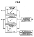
- Fig. 8 is a block diagram representing a calculation processing of a final target deceleration Gt.
- Figs. 9A, 9B, and 9C are integrally a timing chart for explaining an advantage of the first embodiment of the vehicular braking force control apparatus according to the present invention to be compared with the timing chart of Figs. 7A through 7C.
- Fig. 10 is a flowchart for explaining another example of the vehicular braking force control procedure executed in an alternative of the first embodiment of the vehicular braking force control apparatus according to the present invention.
- Fig. 11 is a flowchart for explaining the braking force control procedure executed in a second preferred embodiment of the vehicular braking force control apparatus (when accelerator is ON or when brake is OFF with accelerator OFF) according to the present invention.
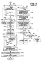
- Fig. 12 is another flowchart continued from the flowchart of Fig. 11 and representing the braking force control procedure (when brake is ON) executed in the second preferred embodiment of the vehicular braking force control apparatus according to the present invention.
- Fig. 13 is a characteristic graph representing a control map used for a calculation of a contribution degree ⁇ as an alternative to the second embodiment.
- Fig. 1 shows a rough configuration view of a brake system.
- a master cylinder 2 which converts a pedal depression force exerted by a vehicle driver inputted to a brake pedal 1 (a brake input device (means)) into a liquid pressure has a primary side communicated with rear left and right wheel cylinders 3RL, 3RR and a secondary side communicated with front left and right wheel cylinders 3FL, 3FR.
- a front-and-rear (road wheel) split system in which the brake system is divided into front and rear road wheels is adopted in this brake system.
- a front-and-rear diagonal split system which divides the brake system into front left and rear right wheel cylinders and front right and rear left wheel cylinders may be adopted in the brake system.
- Each wheel cylinder 3FL through 3RR is built in a disc brake which develops a braking force by grasping a disc rotor with a brake pad under pressure or is built in a drum brake which develops the braking force by pressing a brake shoe onto an inner cylindrical surface of the brake drum under pressure.
- a liquid pressure system at the primary side includes: a gate valve 4r which is closable a flow passage between master cylinder 2 and wheel cylinders 3RL, 3RR; an inlet valve 5RL (or 5RR) which is closable a flow passage between gate valve 4r and wheel cylinder 3RL (or 3 RR); an outlet valve 6RL (or 6RR) which is openable a flow passage communicated between the flow passage between inlet valve 5RL (or 5RR) and wheel cylinder 3RL (3RR) and a reservoir tank 2a of master cylinder 2; and a pump 7r whose suction side is communicated between outlet valve 6RL (6RR) and reservoir tank 2a and whose drain side is communicated between gate valve 4r and inlet valve 5RL (or 5RR).
- each of gate valve 4r, inlet valves 5RL, 5RR, and outlet valves 6RL, 6RR is of a two-port-and-two-position switching spring offset type electromagnetic operating valve.
- Each of gate valve 4r and inlet valves 5RL, 5RR opens the flow passage at a normal position thereof in a non-excitation state.
- Outlet valve 6RL (or 5RR) closes the flow passage at the normal position thereof in the non-excitation state.
- each valve of gate valve 4r and inlet valve 5RL may open the flow passage at an offset position in an excitation state and outlet valves 6RL, 6RR may close the flow passage at the offset position in the excitation state.
- pump 7r is constituted by a volume type pump such as a gear pump, a piston pump which can secure a substantially constant drain quantity regardless of a load pressure.
- inlet valve 5RL (5RR) and outlet valve 6RL (or 6RR) at the normal position in the non-excitation state, gate valve 4r is excited and closed and pump 7r is driven.
- the brake liquid in reservoir tank 2a is sucked by pump 7r and its drain pressure of pump 7r permits the liquid pressure of wheel cylinder 3RL (or 3RR) to be increased.
- outlet valve 6RL (or 6RR) at the normal position in the non-excitation state
- gate valve 4r and inlet valve 5RL (or 5RR) excited to close the respective flow passages the respective flow passages from wheel cylinder 3RL (or 3RR) to reservoir tank 2a and to pump 7r are shut off to enable holding of the liquid pressure in wheel cylinder 3RL (or 3RR).
- outlet valve 6RL (or 6RR) is excited to open the flow passage and gate valve 4r and inlet valve 5RL (or 5RR) are excited to close gate valve 4r and inlet valve 5RL (or 5RR), respectively.
- the liquid pressure of wheel cylinder 3RL (or 3RR) can open to reservoir tank 2a to decrease the liquid pressure.
- a stroke simulator 8 is connected to the secondary side of master cylinder 2.
- This stroke simulator 8 is constituted by a spring type accumulator in which a compression spring 8a is intervened between a bottom portion of the cylinder and the piston. Along with a rise in the liquid pressure, compression spring 8a is elastically shrunk (compressed) so as to generate an appropriate pedal stroke and pedal reaction force for the brake operation by the vehicle driver.
- a controller 9 drivingly controls gate valves 4f, 4r, inlet valves 5FL through 5RR, outlet valves 6FL through 6RR, and pumps 7f, 7r.
- This controller 9 at an ordinary time, executes a braking force control procedure shown in Fig.
- a braking force control on the basis of a pedal stroke quantity Ss detected by a stroke sensor 10 (a stroke quantity detecting section (means) and a master cylinder pressure Pm detected by a pressure sensor 11 (a pressure detecting section (means)) with gate valves 4f, 4r closed and, at a fail-safe time due to a failure of pump 7r or so on, opens gate valves 4f, 4r so that the liquid pressure from master cylinder 2 is transmitted to wheel cylinders 3FL through 3RR to provide the ordinary brake.
- controller 9 reads stroke quantity Ss and master cylinder pressure Pm.
- controller 9 refers to the control map in Fig. 3 and calculates a target deceleration Gs on the basis of stroke quantity Ss.
- the control map is, as shown in Fig.
- target deceleration Gs is increased from zero (0) when stroke quantity Ss is increased from zero (0) and, as stroke quantity Ss becomes larger, an increase rate of target deceleration Gs becomes larger.
- controller 9 refers to the control map shown in Fig. 4 and calculates target deceleration Gp on the basis of master cylinder pressure Pm.
- the control map is set, as shown in Fig. 4, in such a manner that, with master cylinder pressure Pm taken along the lateral axis and with target deceleration Gp taken along the longitudinal axis, target deceleration Gp is proportionally increased when master cylinder pressure Pm is increased from 0.
- controller 9 refers to a control map shown in Fig. 5 and calculates a reference master cylinder pressure Pms from stroke quantity Ss.
- the control map is set in such a manner that, as shown in Fig. 5, with stroke quantity Ss taken along the lateral axis and with reference master cylinder pressure Pms taken along the longitudinal axis, as stroke quantity Ss becomes larger, the increase rate of reference master cylinder pressure Pms becomes larger.
- controller 9 determines whether a deviation (Pm - Pms) between master cylinder pressure Pm and reference master cylinder pressure Pms is equal to or larger than a predetermined value A1.
- a flow passage 12 communicated between master cylinder 2 and stroke simulator 8 mainly provides an orifice for a brake liquid caused to flow from master cylinder 2 to stroke simulator 8.
- a stream speed of the brake liquid caused to flow from master cylinder 2 to stroke simulator 8 is limited due to a flow passage resistance of flow passage 12 at an initial stage of the brake pedal depression.
- master cylinder pressure Pm becomes accordingly larger than a case where the vehicle driver gradually depresses brake pedal 1.
- controller 9 determines that a flow passage resistance of flow passage 12 is not increased and the driver does not depress the brake pedal abruptly (not the abrupt brake operation) and the routine goes to a step S6.
- a control flag F is reset to " 0 ".
- controller 9 determines that the flow passage resistance of flow passage 12 is being increased and determines that there is a possibility that the driver performs the abrupt brake operation and the routine goes to a step S7.
- controller 9 determines that the variation speed of stroke quantity Ss is smaller than predetermined value B and determines that there is a possibility that the vehicle driver does not perform the abrupt brake operation and the routine goes to a step S9.
- controller 9 determines whether deviation (Pm - Pms) between master cylinder pressure Pm and reference master cylinder pressure Pms is equal to or larger than another predetermined value A2. It is noted that predetermined value A2 is larger than previously described predetermined value A1. If the result of determination at step 59 indicates that (Pm - Pms) ⁇ A2, controller 9 determines that the vehicle driver does not perform the abrupt operation of brake pedal 1 and the routine goes to step S6. If result of determination indicates that (Pm - Pms) ⁇ A2 at step S9, the controller 9 determines that the vehicle driver performs the abrupt brake operation and the routine goes to step 58.
- controller 9 refers to a map as shown in the flowchart of Fig. 2 to calculate contribution degrees of both stroke quantity Ss and master cylinder pressure Pm on the calculation of final target deceleration Gt in accordance with master cylinder pressure Pm and a status of control flag F.
- controller 9 calculates a final target deceleration Gt in accordance with target deceleration Gp based on master cylinder pressure Pm, target deceleration Gs based on stroke quantity Ss, and contribution degree ⁇ of master cylinder pressure Pm as shown in equation (1).
- Gt ⁇ • Gp + ( 1 - ⁇ ) • Gs
- the degree of contribution of master cylinder pressure Pm becomes larger.
- the degree of contribution ⁇ becomes smaller, the contribution degree of stroke quantity Ss on the calculation of final target deceleration Gt becomes larger and the degree of contribution of master cylinder pressure Pm becomes accordingly smaller.
- controller 9 calculates target braking force required to achieve final target deceleration Gt. At this time, controller 9 calculates, for example, individually a front road wheel braking force and a rear road wheel braking force and ideally distributes them.
- controller 9 drivingly controls gate valves 4f, 4r, inlet valves 5FL through 5RR, outlet valves 6FL through 6FR, and pump 7f, 7r, respectively.
- stroke sensor 10 corresponds to the stroke quantity detecting section (means)
- pressure sensor 11 corresponds to the pressure detecting section (means)
- a process of step S10 corresponds to a contribution degree setting section (means)
- processes from step S5 through 58 correspond to an abrupt operation detecting section (means).
- controller 9 calculates target deceleration Gs based on stroke quantity Ss and target deceleration Gp based on master cylinder pressure Pm (steps S2 and S3), calculates final target deceleration Gt based on these final deceleration Gs and Gp (step S11), and performs the braking force control in accordance with this final target deceleration Gt (steps S12 and S13).
- a characteristic of stroke simulator 8 is, as shown in Figs. 6A and 6B, as vehicle driver, desiring a large deceleration, depresses more abruptly brake pedal 1, at an initial stage of the pedal depression, the stream speed of the brake liquid flowing from master cylinder 2 to stroke simulator 8 is limited due to the flow passage resistance of flow passage 12.
- master cylinder pressure Pm becomes larger than the case where the vehicle driver depresses brake pedal gradually.
- the pedal stroke does not become larger than desired.
- degree of contribution ⁇ of master cylinder pressure Pm on the calculation of final deceleration Gt is set to become larger when the abrupt brake operation by the vehicle driver is detected (when control flag F is set to " 1 ") than that when the driver's abrupt brake operation is not detected (no abrupt brake operation is detected) (when control flag F is reset to " 0 ") and contribution degree ⁇ of master cylinder pressure Pm used for the calculation of the final target deceleration Gt becomes larger as master cylinder pressure Pm becomes larger.
- degree of contribution of master cylinder pressure Pm becomes increased (step S10).
- controller 9 when controller 9 determines that the flow passage resistance of flow passage 12 which is a liquid pressure transmission path to master cylinder 2 is increased, controller 9 can detect that the abrupt brake operation of the vehicle driver occurs. This abrupt brake operation can, thus, accurately be detected. That is to say, controller 9 calculates reference master cylinder pressure Pms in accordance with stroke quantity Ss detected by stroke sensor 10 at step 54. If deviation (Pm - Pms) between reference master cylinder pressure Pms and master cylinder pressure Pm detected by pressure sensor 11 is equal to or larger than predetermined value A1 (Yes of the determination at step 55), controller 9 can easily and accurately determine that the abrupt brake operation by the vehicle driver occurs due to the determination that the flow passage resistance of flow passage 12 is increased.
- controller 9 determines the abrupt operation of brake by the vehicle driver. Hence, the abrupt operation of the brake can easily and accurately be detected.
- controller 9 detects no abrupt brake operation (when control flag F is reset to " 0 ", degree of contribution ⁇ used for the calculation of final target deceleration Gt becomes smaller than that when controller 9 detects that the abrupt brake operation by the vehicle driver (when control flag F is set to " 1 ") and contribution degree ⁇ becomes smaller as master cylinder pressure Pm becomes lower, namely, the contribution degree of stroke quantity Ss becomes larger (step S10).
- the braking force control in accordance with the general tendency of the vehicle driver to try to adjust the pedal stroke mainly at the initial stage of the pedal depression can be performed.
- a fail safe structure causes gate valve 4f, 4r to be opened and the liquid pressure of master cylinder 2 causes the braking force to be developed.
- the process at step S10 causes degree of contribution ⁇ to be varied in accordance with master cylinder pressure Pm continuously and at an unlimited stage.
- the degree of contribution ⁇ may be varied in a stepwise manner in accordance with master cylinder pressure Pm or may be varied at one stage.
- degree of contribution ⁇ is varied non-linearly (in a curve shape manner) in accordance with the variation of master cylinder pressure Pm.
- the degree of contribution ⁇ may linearly be varied in proportion to the variation in master cylinder pressure Pm.
- degree of contribution ⁇ is exemplified as a distribution percentage (a distribution ratio).
- a sum of ⁇ and (1 - ⁇ ) may not always be constant.
- degree of contribution ⁇ is calculated only in accordance with master cylinder pressure Pm at the process of step S10.
- the present invention is not limited to this. That is to say, degree of contribution ⁇ may be calculated only in accordance with stroke quantity Ss and may be calculated in accordance with both of stroke quantity Ss and master cylinder pressure Pm.
- An OR condition may be used.
- step S7 variation rate (quantity) (Ss (n) - Ss (n-1) ) from stroke quantity Ss (n-1) before one sampling period of sampled stroke quantity Ss (n) is equal to or larger than predetermined value B, in other words, the variation speed of stroke quantity Ss is equal to or larger than the predetermined value
- controller 9 determines that the abrupt brake operation by the vehicle driver occurs.
- the process at step S7 may be modified to a new step 527 as shown in Fig. 10.
- controller 9 may determine that the abrupt brake operation by the vehicle driver occurs.
- the vehicle driver's abrupt brake operation can accurately and easily be detected in the same way in the braking force control procedure shown in Fig. 2.
- a hydraulic brake system in which the liquid pressure is a medium of the transmission is adopted.
- An air brake system in which a compressed air is the medium of transmission may be adopted.
- the brake-by-wire utilizing a fluid pressure is carried out.
- the present invention is not limited to this. Since the braking force control can be carried out, on the brake-by-wire, any brake may be adopted if an electronically controllable energy source such as an electrically operated brake in which an electrically motor operated actuator is drivingly controlled to grasp the disc rotor with the brake pad under pressure and to press a brake shoe on an inner peripheral surface of brake drum under pressure or a regenerative motor brake is provided.
- controller 9 determines whether the accelerator is ON, namely, an accelerator operation by the vehicle driver is carried out. If accelerator operation is not carried out (No) at step S31, the routine goes to a step S38 which will be described later. On the other hand, if the accelerator operation is carried out (accelerator ON), the routine goes to a step S32. At step 532, controller 9 determines whether an accelerator manipulated variable is decreased or not, namely, whether an accelerator release operation occurs. If controller 9 determines that no accelerator release operation occurs at step 532 (No), the routine goes to a step 533. On the other hand, if controller 9 determines that the accelerator release operation occurs (Yes) at step 532, the routine goes to a step S34. At step 533, controller 9 resets control flag F to " 0 " and the routine goes to a step 537.
- controller 9 refers to a control map shown in the flowchart of Fig. 11 in which a threshold value V R for accelerator decrease speed is set in accordance with vehicle speed V.
- This control map is set in such a manner that, with vehicle speed V taken along the lateral axis and threshold value V R taken along the longitudinal axis, threshold value V R is maintained at V R1 (for example, 500 mm/sec) when vehicle speed V is lower than V 1 (for example, 20 Km/h), threshold value V R is decreased between V R1 and V R2 (for example, 200 mm/sec) when vehicle speed V is increased between V 1 and V 2 (for example, 60 Km/h), and threshold value V R is maintained at V R2 when vehicle speed V is in excess of V Z .
- V R1 for example, 500 mm/sec
- V 1 for example, 20 Km/h
- V R2 for example, 200 mm/sec
- V R is maintained at V R2 when vehicle speed V is in excess of V Z .
- V R1 is a maximum release (return) speed determined according to the structure of an accelerator pedal (the accelerator), namely, a value corresponding to a returning speed for the accelerator pedal to be returned to a released position by means of a return spring after a depression force of the accelerator pedal is released and may have a margin to such a degree about -10 %.
- controller 9 determines whether the accelerator decrease speed is equal to or larger than threshold value V R . It is noted that the accelerator decrease speed is calculated from a variation rate from the value one sampling time before the accelerator manipulation variable. It is noted that the result of determination is that the accelerator decrease speed ⁇ V R (No) at step 535, controller 9 determines that the abrupt accelerator release operation by the vehicle driver is not carried out. Hence, controller 9 predicts that the subsequent abrupt brake operation is not carried out and the routine goes to step S33.
- controller 9 determines that the driver's abrupt accelerator return (release) operation is carried out and predicts that the subsequent abrupt brake operation is carried out and the routine goes to a step 536.
- controller 9 sets control flag F to " 1 " and the routine goes to step S37.
- controller 9 sets a provisional setting flag f F indicating a provisional setting state of control flag F to " 1 " and the routine returns to a predetermined main program.
- controller 9 determines whether the brake is OFF, namely, the brake operation is not carried out. If the brake operation is carried out (No), the routine goes to a step S51 shown in Fig. 12 which will be described later. On the other hand, if the brake operation is not present (Yes), the routine goes to a step 539.
- controller 9 sets a timer flag f T indicating a count start state by means of timer T to " 1 " to indicate the count start state by means of timer T and the routine is returned to the predetermined main program.
- controller 9 refers to a control map shown in the flowchart of Fig. 12 in which threshold value T C for timer T is set in accordance with vehicle speed V.
- This control map is set in such a manner that, with vehicle speed V taken along the lateral axis and threshold value T C taken along the longitudinal axis, threshold value T C is increased between T C1 (for example, 0.2 Sec.) and T C2 (for example, 0.5 Sec,) when vehicle speed V is increased from zero to V 2 (for example, 60 Km/h) and threshold value T C is maintained at T C2 when vehicle speed V is in excess of V 2 ,
- Tc1 is a time required for an ordinary human being to reflectively shift a pedal depression from the accelerator pedal to brake pedal 1
- T C2 is a time required for a human being to shift the pedal depression even if the human being has a slow response capability (a slow reflexes).
- controller 9 determines whether the count value of timer T is equal to or longer than threshold value T C . If the result of determination at step 553 is T ⁇ T C (Yes), the brake operation is not started instantaneously after the accelerator operation is released. Hence, controller 9 predicts that the abrupt brake operation is not carried out, the routine goes to a step S54. If the result of determination at step 553 is T ⁇ T c , the brake operation is started immediately after the accelerator operation is released, hence, controller 9 predicts that the abrupt brake operation is carried out, and the routine goes to a step S55.
- controller 9 resets control flag F to " 0 " and the routine goes to a step S56.
- controller 9 sets control flag F to " 1 " and the routine goes to a step S56,
- timer T is reset to " 0 ",
- timer flag f T is reset to " 0 ".
- provisional setting flag f F is reset to " 0 " and the routine goes to step S10 described with reference to Fig. 2.
- controller 9 predicts that the subsequent abrupt brake operation occurs and sets control flag F to " 1 " as a provisional setting. (step 536).
- degree of contribution ⁇ of master cylinder pressure Pm becomes larger.
- the response characteristic can be higher by a detection time rather than the response from the actual detection of the abrupt brake operation.
- the large deceleration that the driver desires can accurately be assured from the initial stage of the start of the brake operation.
- the response characteristic of the second embodiment is particularly superior.
- the determination of whether the abrupt brake operation occurs is carried out depending upon whether the decrease speed of the accelerator operation is equal to or larger than threshold value V R .
- threshold value V R for the accelerator decrease speed is set to a smaller value as vehicle speed V becomes faster (step S34).
- the response characteristic at a high speed range which gives a large influence on a braking distance can become easier to be higher.
- the superior response characteristic to the abrupt brake operation at the high vehicle speed range is exhibited.
- the large deceleration that the vehicle driver desires form the initial stage is obtained so that the braking distance can as short as possible.
- step 540 the time duration from the time at which the accelerator operation is released to the time at which the brake operation is started (the pedal depression shift time) is counted by means of timer T (step 540).
- timer count value T at the time point at which the brake operation is started is less than threshold value T C (" No " at the determination of step S53)
- controller 9 predicts that the abrupt brake operation will be carried out from this time and control flag F is set to " 1 ". (step S55).
- the prediction is carried out from a time at which the brake operation is actually started, a reliability can be improved rather than a case of the prediction at the stage of the release of the accelerator operation.
- the determination of whether the abrupt brake operation is carried out is carried out depending upon whether the count value of timer T is shorter than threshold value T C . Hence, this can easily and accurately be determined.
- threshold value T C for timer value T is set to become longer as vehicle speed V becomes faster (step S52).
- the response characteristic at the high speed range at which vehicle speed V gives the large influence on the braking distance becomes easier to be higher. Therefore, the superior response characteristic to the abrupt brake operation at the high speed range can be exhibited. From the initial stage, the large deceleration in the way as the vehicle driver desires is obtained. The braking distance can be shortened as short as possible..
- a reliability of the prediction is improved in a case where the prediction that the abrupt brake operation occurs in accordance with the pedal depression shift time (timer T) rather than the case where the abrupt brake deceleration is carried out at the time point at which the abrupt accelerator release operation is detected.
- timer T the count value of timer T is equal to or larger than threshold value T C (the determination at step S53 is Yes).
- control flag F previously set provisional setting
- the reliability of the prediction is not reduced.
- the abrupt accelerator release operation is detected in accordance with the decrease speed of the accelerator operation.
- controller 9 may detect the abrupt accelerator release operation.
- control flag F is reset to " 0 " when the count value of timer T is equal to or larger (longer) than threshold value T c .
- the abrupt brake operation is predicted in accordance with the abrupt accelerator release operation and the pedal depression time (timer value T).
- the present invention is not limited to this.
- the prediction of the abrupt brake operation may be carried out in accordance with a relative relationship between the vehicle and a preceding vehicle which is traveling ahead of the vehicle. That is to say, when an inter-vehicle distance from the preceding vehicle is abruptly decreased from a state in which the inter-vehicle distance is approximately constant, or when the inter-vehicle distance from the preceding vehicle is shorter than a shortest braking distance, there is a possibility that the vehicle driver carries out the abrupt brake operation.
- controller 9 may respond to such that degree of contribution ⁇ of master cylinder pressure Pm becomes larger.
Landscapes
- Engineering & Computer Science (AREA)
- Physics & Mathematics (AREA)
- Fluid Mechanics (AREA)
- Transportation (AREA)
- Mechanical Engineering (AREA)
- Regulating Braking Force (AREA)
Abstract
Description
- The present invention relates to vehicular braking force control method and vehicular braking force control apparatus in which a braking force is controlled in accordance with a brake operation by a vehicle driver, in other words, a, so-called, brake-by-wire is performed.
- A Japanese Patent Application First Publication No. Heisei 11-301434 published on November 2, 1999 exemplifies a previously proposed vehicular braking force control apparatus. In the previously proposed braking force control apparatus disclosed in the above-described Japanese Patent Application First Publication, a target braking force is calculated on the basis of a master cylinder pressure and a stroke of a brake pedal and a vehicular braking force is controlled in accordance with the target braking force. Contribution degrees of the master cylinder pressure and the pedal stroke are modified in accordance with at least one of the master cylinder pressure and the pedal stroke. Especially, at an initial stage of a pedal depression, the contribution degree of the pedal stroke is made larger than the contribution degree of the master cylinder pressure. This is because there is a general tendency that the vehicle driver tries to mainly adjust the pedal stroke at a low deceleration region in which a desired deceleration is low and tries to mainly adjust a pedal depression force at a high deceleration region in which the desired deceleration is high.
- In a case where the brake-by-wire is performed, a stroke simulator which elastically shrinks according to a liquid pressure developed in the master cylinder is provided in order to generate an appropriate pedal stroke and a pedal reaction force for a brake operation by the vehicle driver. A flow passage mainly communicated between the master cylinder and the stroke simulator provides an orifice for a brake liquid which is caused to flow from the master cylinder to the stroke simulator. Hence, as the vehicle driver more abruptly depresses the brake pedal desiring the large deceleration, a stream speed of the brake liquid caused to flow from the master cylinder to the stroke simulator is more limited at an initial stage of the abrupt pedal depression. Thus, the master cylinder pressure becomes larger than that when the vehicle driver gradually depresses the brake pedal. In addition, by the limitation of the stream speed of the brake liquid, the brake pedal doest not stroke as the vehicle driver intends.
- However, in the previously proposed braking force control apparatus disclosed in the above-described Japanese Patent Application First Publication, the target braking force is calculated with the contribution degree of the pedal stroke set to be large at the initial stage of the pedal stroke. Hence, even though the master cylinder pressure becomes large when the brake pedal is abruptly depressed by the vehicle driver, the contribution degree of the master cylinder pressure on an increase in the target deceleration is low. That is to say, even if the vehicle driver abruptly depresses the brake pedal desiring the large deceleration, the pedal stroke is not increased to a degree that the vehicle driver desires, at the initial stage of the pedal depression. It is difficult to say that an intention of the vehicle driver is accurately reflected on the target braking force.
- With the above-described point in mind, it is an object of the present invention to provide braking force control method for an automotive vehicle and braking force control apparatus therefor which are capable of reflecting accurately the intention of the vehicle driver on the target braking force even at the initial stage of the brake operation.
- To achieve the above-described object, according to one aspect of the present invention, there is provided with a braking force control method for an automotive vehicle, comprising: providing a brake input device manually operable by a vehicle driver; providing a master cylinder configured to develop a master cylinder pressure in accordance with an operation of the brake input device by the vehicle driver; setting contribution degrees of both of a stroke quantity of the brake input device and the master cylinder pressure in accordance with at least one of the stroke quantity of the brake input device and the master cylinder pressure developed in the master cylinder; calculating a target braking force of the vehicle on the basis of the contribution degrees of both of the stroke quantity and the master cylinder pressure; and controlling the braking force of the vehicle in accordance with the calculated target braking force, the contribution degree of the master cylinder pressure on a calculation of the target braking force being set to become larger when an abrupt brake operation by the vehicle driver is detected than the contribution degree of the master cylinder pressure when no abrupt brake operation by the vehicle driver is detected.
- To achieve the above-described object, according to another aspect of the present invention, there is provided with a braking force control apparatus for an automotive vehicle, comprising: a brake input device manually operable by a vehicle driver; a master cylinder configured to develop a master cylinder pressure in accordance with an operation of the brake input device by the vehicle driver; a contribution degree setting section that sets contribution degrees of both of a stroke quantity of the brake input device and the master cylinder pressure in accordance with at least one of the stroke quantity of the brake input device and the master cylinder pressure developed in the master cylinder; a target braking force calculating section that calculates a target braking force of the vehicle on the basis of the contribution degrees of both of the stroke quantity of the brake input device and the master cylinder pressure; and a braking force control section that controls the braking force of the vehicle in accordance with the calculated target braking force, the contribution degree setting section setting the contribution degree of the master cylinder pressure on a calculation of the target braking force to become larger when an abrupt brake operation by the vehicle driver is detected than the contribution degree of the master cylinder pressure when no abrupt brake operation by the vehicle driver is detected. It is noted that the abrupt brake operation is defined as a brake operation such that an operation speed or an operation acceleration of a brake operation of the brake input device (namely, a brake pedal) by the vehicle driver provides a large value (for example, 0.3 G or larger) for a previously set value corresponding to the brake operation during an ordinary street run of the vehicle.
- This summary of the invention does not necessarily describe all necessary features so that the present invention may also be a sub-combination of these described features.
- Fig. 1 is a rough configuration view of a vehicular brake system.
- Fig. 2 is a flowchart for explaining a braking force control procedure executed in a first preferred embodiment of a vehicular braking force control apparatus according to the present invention.
- Fig. 3 is a characteristic graph representing a control map used for a calculation of a target deceleration Gs for a stroke quantity Ss.
- Fig. 4 is a characteristic graph representing a control map used for a calculation of another target deceleration Gp for a master cylinder pressure Pm.
- Fig. 5 is a characteristic graph representing a control map used for a calculation of a reference master cylinder pressure Pms.
- Figs. 6A and 6B are integrally a characteristic graph representing a characteristic of a stroke simulator.
- Figs. 7A, 7B, and 7C are integrally a timing chart for explaining a problem of a comparative example to the first embodiment of the vehicular braking force control apparatus.
- Fig. 8 is a block diagram representing a calculation processing of a final target deceleration Gt.
- Figs. 9A, 9B, and 9C are integrally a timing chart for explaining an advantage of the first embodiment of the vehicular braking force control apparatus according to the present invention to be compared with the timing chart of Figs. 7A through 7C.
- Fig. 10 is a flowchart for explaining another example of the vehicular braking force control procedure executed in an alternative of the first embodiment of the vehicular braking force control apparatus according to the present invention.
- Fig. 11 is a flowchart for explaining the braking force control procedure executed in a second preferred embodiment of the vehicular braking force control apparatus (when accelerator is ON or when brake is OFF with accelerator OFF) according to the present invention.
- Fig. 12 is another flowchart continued from the flowchart of Fig. 11 and representing the braking force control procedure (when brake is ON) executed in the second preferred embodiment of the vehicular braking force control apparatus according to the present invention.
- Fig. 13 is a characteristic graph representing a control map used for a calculation of a contribution degree α as an alternative to the second embodiment.
- Reference will hereinafter be made to the drawings in order to facilitate a better understanding of the present invention.
- Fig. 1 shows a rough configuration view of a brake system. A
master cylinder 2 which converts a pedal depression force exerted by a vehicle driver inputted to a brake pedal 1 (a brake input device (means)) into a liquid pressure has a primary side communicated with rear left and right wheel cylinders 3RL, 3RR and a secondary side communicated with front left and right wheel cylinders 3FL, 3FR. In this case, a front-and-rear (road wheel) split system in which the brake system is divided into front and rear road wheels is adopted in this brake system. It is of course that a front-and-rear diagonal split system which divides the brake system into front left and rear right wheel cylinders and front right and rear left wheel cylinders may be adopted in the brake system. - Each wheel cylinder 3FL through 3RR is built in a disc brake which develops a braking force by grasping a disc rotor with a brake pad under pressure or is built in a drum brake which develops the braking force by pressing a brake shoe onto an inner cylindrical surface of the brake drum under pressure. A liquid pressure system at the primary side includes: a
gate valve 4r which is closable a flow passage betweenmaster cylinder 2 and wheel cylinders 3RL, 3RR; an inlet valve 5RL (or 5RR) which is closable a flow passage betweengate valve 4r and wheel cylinder 3RL (or 3 RR); an outlet valve 6RL (or 6RR) which is openable a flow passage communicated between the flow passage between inlet valve 5RL (or 5RR) and wheel cylinder 3RL (3RR) and areservoir tank 2a ofmaster cylinder 2; and a pump 7r whose suction side is communicated between outlet valve 6RL (6RR) andreservoir tank 2a and whose drain side is communicated betweengate valve 4r and inlet valve 5RL (or 5RR). - It is noted that each of
gate valve 4r, inlet valves 5RL, 5RR, and outlet valves 6RL, 6RR is of a two-port-and-two-position switching spring offset type electromagnetic operating valve. Each ofgate valve 4r and inlet valves 5RL, 5RR opens the flow passage at a normal position thereof in a non-excitation state. Outlet valve 6RL (or 5RR) closes the flow passage at the normal position thereof in the non-excitation state. It is also noted that, since each valve can open or close the flow passage, each valve ofgate valve 4r and inlet valve 5RL (or 5RR) may open the flow passage at an offset position in an excitation state and outlet valves 6RL, 6RR may close the flow passage at the offset position in the excitation state. - In addition, pump 7r is constituted by a volume type pump such as a gear pump, a piston pump which can secure a substantially constant drain quantity regardless of a load pressure. In the above-described structure, with inlet valve 5RL (5RR) and outlet valve 6RL (or 6RR) at the normal position in the non-excitation state,
gate valve 4r is excited and closed and pump 7r is driven. Thus, the brake liquid inreservoir tank 2a is sucked by pump 7r and its drain pressure of pump 7r permits the liquid pressure of wheel cylinder 3RL (or 3RR) to be increased. - With outlet valve 6RL (or 6RR) at the normal position in the non-excitation state,
gate valve 4r and inlet valve 5RL (or 5RR) excited to close the respective flow passages, the respective flow passages from wheel cylinder 3RL (or 3RR) toreservoir tank 2a and to pump 7r are shut off to enable holding of the liquid pressure in wheel cylinder 3RL (or 3RR). Furthermore, outlet valve 6RL (or 6RR) is excited to open the flow passage andgate valve 4r and inlet valve 5RL (or 5RR) are excited to closegate valve 4r and inlet valve 5RL (or 5RR), respectively. Thus, the liquid pressure of wheel cylinder 3RL (or 3RR) can open toreservoir tank 2a to decrease the liquid pressure. - Furthermore, with all of
gate valve 4r, inlet valve 5RL (or 5RR), and outlet valve 6RL (or 6RR) set to the normal position in the non-exciting state, the liquid pressure frommaster cylinder 2 is transmitted to wheel cylinder 3RL (or 3RR) and provides an ordinary brake. It is noted that, in the liquid pressure system at the secondary side, the same gate valve 4f, inlet valve 5FL (or 5FR), outlet valve 6FL, 6FR, and pump 7f are installed. Since the respective valve operations are the same as the primary side, the detailed description will herein be omitted. - A
stroke simulator 8 is connected to the secondary side ofmaster cylinder 2. Thisstroke simulator 8 is constituted by a spring type accumulator in which acompression spring 8a is intervened between a bottom portion of the cylinder and the piston. Along with a rise in the liquid pressure,compression spring 8a is elastically shrunk (compressed) so as to generate an appropriate pedal stroke and pedal reaction force for the brake operation by the vehicle driver. - A controller 9 drivingly controls
gate valves 4f, 4r, inlet valves 5FL through 5RR, outlet valves 6FL through 6RR, and pumps 7f, 7r. This controller 9, at an ordinary time, executes a braking force control procedure shown in Fig. 2 so as to performs the brake-by-wire, namely, a braking force control on the basis of a pedal stroke quantity Ss detected by a stroke sensor 10 (a stroke quantity detecting section (means) and a master cylinder pressure Pm detected by a pressure sensor 11 (a pressure detecting section (means)) withgate valves 4f, 4r closed and, at a fail-safe time due to a failure of pump 7r or so on, opensgate valves 4f, 4r so that the liquid pressure frommaster cylinder 2 is transmitted to wheel cylinders 3FL through 3RR to provide the ordinary brake. - Next, the braking force control procedure in the first preferred embodiment executed by controller 9 will be described on the basis of a flowchart shown in Fig. 2. This braking force control procedure is executed as a timer interrupt processing for each predetermined time (for example, 10 milliseconds). As shown in Fig. 2, at a first step S1, controller 9 reads stroke quantity Ss and master cylinder pressure Pm. At the subsequent step S2, controller 9 refers to the control map in Fig. 3 and calculates a target deceleration Gs on the basis of stroke quantity Ss. The control map is, as shown in Fig. 3, set in such a manner that, with stroke quantity Ss taken along a lateral axis and with target deceleration Gs taken along a longitudinal axis, target deceleration Gs is increased from zero (0) when stroke quantity Ss is increased from zero (0) and, as stroke quantity Ss becomes larger, an increase rate of target deceleration Gs becomes larger.
- At the subsequent step S3, controller 9 refers to the control map shown in Fig. 4 and calculates target deceleration Gp on the basis of master cylinder pressure Pm. The control map is set, as shown in Fig. 4, in such a manner that, with master cylinder pressure Pm taken along the lateral axis and with target deceleration Gp taken along the longitudinal axis, target deceleration Gp is proportionally increased when master cylinder pressure Pm is increased from 0. At the subsequent step 54, controller 9 refers to a control map shown in Fig. 5 and calculates a reference master cylinder pressure Pms from stroke quantity Ss. The control map is set in such a manner that, as shown in Fig. 5, with stroke quantity Ss taken along the lateral axis and with reference master cylinder pressure Pms taken along the longitudinal axis, as stroke quantity Ss becomes larger, the increase rate of reference master cylinder pressure Pms becomes larger.
- At the
subsequent step 55, controller 9 determines whether a deviation (Pm - Pms) between master cylinder pressure Pm and reference master cylinder pressure Pms is equal to or larger than a predetermined value A1. Aflow passage 12 communicated betweenmaster cylinder 2 andstroke simulator 8 mainly provides an orifice for a brake liquid caused to flow frommaster cylinder 2 tostroke simulator 8. Hence, asbrake pedal 1 is abruptly depressed desiring a large deceleration by the vehicle driver, a stream speed of the brake liquid caused to flow frommaster cylinder 2 tostroke simulator 8 is limited due to a flow passage resistance offlow passage 12 at an initial stage of the brake pedal depression. Hence, master cylinder pressure Pm becomes accordingly larger than a case where the vehicle driver gradually depressesbrake pedal 1. - Hence, if a result of determination at
step 55 indicates (Pm - Pms) < A1, controller 9 determines that a flow passage resistance offlow passage 12 is not increased and the driver does not depress the brake pedal abruptly (not the abrupt brake operation) and the routine goes to a step S6. At step S6, a control flag F is reset to " 0 ". On the other hand, if the determination result is (Pm - Pms) ≥ A1 at step S5, controller 9 determines that the flow passage resistance offlow passage 12 is being increased and determines that there is a possibility that the driver performs the abrupt brake operation and the routine goes to a step S7. - At step S7, controller 9 determines whether a variation rate (Ss(n) - Ss(n-1)) from stroke quantity Ss(n-1) before one sampling time of sampled present stroke quantity Ss(n) (n = natural number) is equal to or larger than a predetermined value B. If this determination result at step S7 indicates (Ss(n) - Ss(n-1)) ≥ B, controller 9 determines that a variation speed of stroke quantity Ss is equal to or larger than the predetermined value and determines that there is a possibility that the vehicle driver performs the abrupt brake operation and the routine goes to a step S8. At step S8, controller 9 sets control flag F to " 1 ". On the other hand, if the result of determination indicates (Ss (n) - Ss(n-1)) < B at step 57, controller 9 determines that the variation speed of stroke quantity Ss is smaller than predetermined value B and determines that there is a possibility that the vehicle driver does not perform the abrupt brake operation and the routine goes to a step S9.
- At
step 59, controller 9 determines whether deviation (Pm - Pms) between master cylinder pressure Pm and reference master cylinder pressure Pms is equal to or larger than another predetermined value A2. It is noted that predetermined value A2 is larger than previously described predetermined value A1. If the result of determination atstep 59 indicates that (Pm - Pms) < A2, controller 9 determines that the vehicle driver does not perform the abrupt operation ofbrake pedal 1 and the routine goes to step S6. If result of determination indicates that (Pm - Pms) ≥ A2 at step S9, the controller 9 determines that the vehicle driver performs the abrupt brake operation and the routine goes to step 58. - At a step S10 subsequent to step S8 or 56, controller 9 refers to a map as shown in the flowchart of Fig. 2 to calculate contribution degrees of both stroke quantity Ss and master cylinder pressure Pm on the calculation of final target deceleration Gt in accordance with master cylinder pressure Pm and a status of control flag F. The control map is set in such a manner that, with master cylinder pressure Pm taken along lateral line and with contribution degree α of master cylinder pressure Pm taken along longitudinal line, contribution degree α is increased in a range from 0 to 1 and contribution degree α of master cylinder pressure Pm becomes larger when F = 1 than that when F = 0.
- At step S11, controller 9 calculates a final target deceleration Gt in accordance with target deceleration Gp based on master cylinder pressure Pm, target deceleration Gs based on stroke quantity Ss, and contribution degree α of master cylinder pressure Pm as shown in equation (1).

According to equation (1), as a value of contribution degree α becomes larger, the degree of contribution of stroke quantity Ss becomes smaller on the calculation of final target deceleration Gt. At this time, the degree of contribution of master cylinder pressure Pm becomes larger. On the contrary, as the degree of contribution α becomes smaller, the contribution degree of stroke quantity Ss on the calculation of final target deceleration Gt becomes larger and the degree of contribution of master cylinder pressure Pm becomes accordingly smaller. - At the subsequent step S12, controller 9 calculates target braking force required to achieve final target deceleration Gt. At this time, controller 9 calculates, for example, individually a front road wheel braking force and a rear road wheel braking force and ideally distributes them. At the subsequent step 513, controller 9 drivingly controls
gate valves 4f, 4r, inlet valves 5FL through 5RR, outlet valves 6FL through 6FR, and pump 7f, 7r, respectively. - As described above,
stroke sensor 10 corresponds to the stroke quantity detecting section (means),pressure sensor 11 corresponds to the pressure detecting section (means), a process of step S10 corresponds to a contribution degree setting section (means), and processes from step S5 through 58 correspond to an abrupt operation detecting section (means). - Next, operation, action, and advantages of the first embodiment of the braking force control apparatus will be described below. Suppose, now that an ordinary brake by wire is carried out. That is to say, with
gate valves 4f, 4r closed, inlet valves 5FL through 5RR, outlet valves 6FL through 6RR, and pumps 7f, 7r are drivingly controlled and the braking force control in accordance with the brake operation by the vehicle driver is carried out. - That is to say, controller 9 calculates target deceleration Gs based on stroke quantity Ss and target deceleration Gp based on master cylinder pressure Pm (steps S2 and S3), calculates final target deceleration Gt based on these final deceleration Gs and Gp (step S11), and performs the braking force control in accordance with this final target deceleration Gt (steps S12 and S13). A characteristic of
stroke simulator 8 is, as shown in Figs. 6A and 6B, as vehicle driver, desiring a large deceleration, depresses more abruptly brakepedal 1, at an initial stage of the pedal depression, the stream speed of the brake liquid flowing frommaster cylinder 2 tostroke simulator 8 is limited due to the flow passage resistance offlow passage 12. Hence, master cylinder pressure Pm becomes larger than the case where the vehicle driver depresses brake pedal gradually. In addition, the pedal stroke does not become larger than desired. - Therefore, at the initial stage of pedal depression at which the driver performs the abrupt brake operation, the degree of contribution of stroke quantity Ss becomes large and final target deceleration Gt is calculated. At this time, the degree of contribution of the increase of master cylinder pressure Pm on the increase in final target deceleration Gt becomes low. Consequently, as shown in Figs. 7A through 7C which show an operation of a comparative example in the case where the degree of contribution of the increase in the master cylinder pressure Pm on the increase in the final target deceleration Gt becomes low as described above to the first embodiment, although the vehicle driver depresses
brake pedal 1 abruptly desiring the large deceleration,brake pedal 1 does not stroke as desired due to the flow passage resistance offlow passage 12. At the initial stage of the pedal depression ofbrake pedal 1, final target deceleration Gt is not increased (refer to Fig. 7C) to a degree that the vehicle driver desires and the driver's intention cannot accurately be reflected. - Thus, degree of contribution α of master cylinder pressure Pm on the calculation of final deceleration Gt is set to become larger when the abrupt brake operation by the vehicle driver is detected (when control flag F is set to " 1 ") than that when the driver's abrupt brake operation is not detected (no abrupt brake operation is detected) (when control flag F is reset to " 0 ") and contribution degree α of master cylinder pressure Pm used for the calculation of the final target deceleration Gt becomes larger as master cylinder pressure Pm becomes larger. In other words, degree of contribution of master cylinder pressure Pm becomes increased (step S10).
- It is noted that the calculation processing of final target deceleration Gt in the first embodiment is shown in Fig. 8. Thus, as shown in Figs. 9A through 9C (particularly Fig. 9C), when master cylinder pressure Pm becomes larger due to the execution of the abrupt brake operation by the vehicle driver, a rising of final target deceleration Gt is improved. By reducing an arrival time at a predetermined deceleration speed, a delay in the vehicular deceleration can be improved. Hence, final target deceleration Gt is increased to a value that the vehicle driver desires. From the initial stage of the brake operation, the vehicle driver's intention can accurately be reflected and an effect of braking can be exhibited at an earlier stage of the braking.
- In addition, when controller 9 determines that the flow passage resistance of
flow passage 12 which is a liquid pressure transmission path tomaster cylinder 2 is increased, controller 9 can detect that the abrupt brake operation of the vehicle driver occurs. This abrupt brake operation can, thus, accurately be detected. That is to say, controller 9 calculates reference master cylinder pressure Pms in accordance with stroke quantity Ss detected bystroke sensor 10 at step 54. If deviation (Pm - Pms) between reference master cylinder pressure Pms and master cylinder pressure Pm detected bypressure sensor 11 is equal to or larger than predetermined value A1 (Yes of the determination at step 55), controller 9 can easily and accurately determine that the abrupt brake operation by the vehicle driver occurs due to the determination that the flow passage resistance offlow passage 12 is increased. - Furthermore, when the increase speed of stroke quantity Ss detected by
stroke sensor 10, namely, variation quantity (Ss(n) - Ss(n-1)) of sampled stroke quantity Ss(n) from one sampling period prior stroke quantity Ss(n-1) is equal to or lager than predetermined value B (Yes at step S7), controller 9 determines the abrupt operation of brake by the vehicle driver. Hence, the abrupt operation of the brake can easily and accurately be detected. - On the other hand, when controller 9 detects no abrupt brake operation (when control flag F is reset to " 0 ", degree of contribution α used for the calculation of final target deceleration Gt becomes smaller than that when controller 9 detects that the abrupt brake operation by the vehicle driver (when control flag F is set to " 1 ") and contribution degree α becomes smaller as master cylinder pressure Pm becomes lower, namely, the contribution degree of stroke quantity Ss becomes larger (step S10). Thus, the braking force control in accordance with the general tendency of the vehicle driver to try to adjust the pedal stroke mainly at the initial stage of the pedal depression can be performed.
- When a pump failure, for example, is detected from a state in which the brake-by-wire is performed, a fail safe structure causes
gate valve 4f, 4r to be opened and the liquid pressure ofmaster cylinder 2 causes the braking force to be developed. It is noted that, in the first embodiment described above, the process at step S10 causes degree of contribution α to be varied in accordance with master cylinder pressure Pm continuously and at an unlimited stage. The present invention is not limited to this. The degree of contribution α may be varied in a stepwise manner in accordance with master cylinder pressure Pm or may be varied at one stage. Furthermore, degree of contribution α is varied non-linearly (in a curve shape manner) in accordance with the variation of master cylinder pressure Pm. However, the present invention is not limited to this. The degree of contribution α may linearly be varied in proportion to the variation in master cylinder pressure Pm. - In addition, degree of contribution α is exemplified as a distribution percentage (a distribution ratio). A sum of α and (1 - α) may not always be constant. For example, such a form that one of the degrees of contributions is increased but the other degree of contribution is unchanged and the sum may accordingly be increased. In addition, in the first embodiment, degree of contribution α is calculated only in accordance with master cylinder pressure Pm at the process of step S10. The present invention is not limited to this. That is to say, degree of contribution α may be calculated only in accordance with stroke quantity Ss and may be calculated in accordance with both of stroke quantity Ss and master cylinder pressure Pm. In addition, although the vehicle driver's abrupt brake operation is detected by an AND condition between the determination processing of step S5 and the determination processing of step 57, The present invention is not limited to this. An OR condition may be used.
- If, in the first preferred embodiment described above, at the processing of step S7, variation rate (quantity) (Ss(n) - Ss (n-1)) from stroke quantity Ss (n-1) before one sampling period of sampled stroke quantity Ss(n) is equal to or larger than predetermined value B, in other words, the variation speed of stroke quantity Ss is equal to or larger than the predetermined value, controller 9 determines that the abrupt brake operation by the vehicle driver occurs. However, the present invention is not limited to this. The process at step S7 may be modified to a new step 527 as shown in Fig. 10. That is to say, if a variation rate (quantity) (Pm(n) - Pm(n-1)) from master cylinder pressure Pm(n-1) before one sampling period of sampled present master cylinder Pm(n) is equal to or larger than a predetermined value C, in other words, if a variation speed of master cylinder pressure Pm is equal to or larger than the predetermined value, controller 9 may determine that the abrupt brake operation by the vehicle driver occurs. Thus, the vehicle driver's abrupt brake operation can accurately and easily be detected in the same way in the braking force control procedure shown in Fig. 2.
- In the first embodiment, a hydraulic brake system in which the liquid pressure is a medium of the transmission is adopted. However, the present invention is not limited to this. An air brake system in which a compressed air is the medium of transmission may be adopted. Furthermore, in the first embodiment, the brake-by-wire utilizing a fluid pressure is carried out. However, the present invention is not limited to this. Since the braking force control can be carried out, on the brake-by-wire, any brake may be adopted if an electronically controllable energy source such as an electrically operated brake in which an electrically motor operated actuator is drivingly controlled to grasp the disc rotor with the brake pad under pressure and to press a brake shoe on an inner peripheral surface of brake drum under pressure or a regenerative motor brake is provided.
- Next, a second preferred embodiment of the braking force control apparatus according to the present invention will be described on the basis of Figs. 11 through 13. The specific structure of the braking force control apparatus in the second embodiment is the same as that in the first embodiment. In the second embodiment of the braking force control apparatus according to the present invention, degree of contribution α of master cylinder pressure Pm on the calculation of final target deceleration Gt when controller 9 predicts that the abrupt brake operation by the driver occurs is made larger than that when controller 9 does not predict that the abrupt brake operation by the driver occurs. Thus, in the second embodiment, except that the braking force control procedure in Fig. 2 is modified to the braking force control procedure shown in Figs. 11 and 12, the same processing as described in the first embodiment is executed. It is noted that the detailed description of the same reference numeral steps as those shown in Fig. 2 will be omitted herein.
- First, at step S31 in Fig. 11, controller 9 determines whether the accelerator is ON, namely, an accelerator operation by the vehicle driver is carried out. If accelerator operation is not carried out (No) at step S31, the routine goes to a step S38 which will be described later. On the other hand, if the accelerator operation is carried out (accelerator ON), the routine goes to a step S32. At
step 532, controller 9 determines whether an accelerator manipulated variable is decreased or not, namely, whether an accelerator release operation occurs. If controller 9 determines that no accelerator release operation occurs at step 532 (No), the routine goes to a step 533. On the other hand, if controller 9 determines that the accelerator release operation occurs (Yes) atstep 532, the routine goes to a step S34. At step 533, controller 9 resets control flag F to " 0 " and the routine goes to a step 537. - At step 534, controller 9 refers to a control map shown in the flowchart of Fig. 11 in which a threshold value VR for accelerator decrease speed is set in accordance with vehicle speed V. This control map is set in such a manner that, with vehicle speed V taken along the lateral axis and threshold value VR taken along the longitudinal axis, threshold value VR is maintained at VR1 (for example, 500 mm/sec) when vehicle speed V is lower than V1 (for example, 20 Km/h), threshold value VR is decreased between VR1 and VR2 (for example, 200 mm/sec) when vehicle speed V is increased between V1 and V2 (for example, 60 Km/h), and threshold value VR is maintained at VR2 when vehicle speed V is in excess of VZ. It is noted that VR1 is a maximum release (return) speed determined according to the structure of an accelerator pedal (the accelerator), namely, a value corresponding to a returning speed for the accelerator pedal to be returned to a released position by means of a return spring after a depression force of the accelerator pedal is released and may have a margin to such a degree about -10 %.
- At the next step S35, controller 9 determines whether the accelerator decrease speed is equal to or larger than threshold value VR. It is noted that the accelerator decrease speed is calculated from a variation rate from the value one sampling time before the accelerator manipulation variable. It is noted that the result of determination is that the accelerator decrease speed < VR (No) at step 535, controller 9 determines that the abrupt accelerator release operation by the vehicle driver is not carried out. Hence, controller 9 predicts that the subsequent abrupt brake operation is not carried out and the routine goes to step S33. On the other hand, if the result of determination at step 535 is that accelerator decrease speed ≥ VR, controller 9 determines that the driver's abrupt accelerator return (release) operation is carried out and predicts that the subsequent abrupt brake operation is carried out and the routine goes to a step 536.
- At step S36, controller 9 sets control flag F to " 1 " and the routine goes to step S37. At step 537, controller 9 sets a provisional setting flag fF indicating a provisional setting state of control flag F to " 1 " and the routine returns to a predetermined main program. On the other hand, at step S38, controller 9 determines whether the brake is OFF, namely, the brake operation is not carried out. If the brake operation is carried out (No), the routine goes to a step S51 shown in Fig. 12 which will be described later. On the other hand, if the brake operation is not present (Yes), the routine goes to a step 539.
- At step S39, controller 9 determines whether provisional setting flag fF is set to " 1". If the result of determination is fF = 0, controller 9 determines that the accelerator operation is naturally not carried out after, for example, an ignition switch is turned to ON and the routine is returned to the predetermined main program. On the other hand, if result of determination is fF = 1, controller 9 determines that it (the present time) is after the accelerator operation is released and the routine goes to a step S40.
- At step S40, controller 9 counts a time from a time at which the accelerator operation is released to a time at which the brake operation is started by means of a timer T (T = T + 1). At the subsequent step S41, controller 9 sets a timer flag fT indicating a count start state by means of timer T to " 1 " to indicate the count start state by means of timer T and the routine is returned to the predetermined main program. On the other hand, at step S51 in Fig. 12, controller 9 determines whether timer flag fT is set to " 1 ". If the result of determination at step S51 is fT = 0, controller 9 determines that this brake operation is not the brake operation after the accelerator operation is released and the routine goes to a step S59 which will be described later. On the other hand, if the result of determination at step S51 is fT = 1 (Yes), controller 9 determines that this brake operation is the brake operation after the release of the accelerator operation and the routine goes to a step S52.
- At step 552, controller 9 refers to a control map shown in the flowchart of Fig. 12 in which threshold value TC for timer T is set in accordance with vehicle speed V. This control map is set in such a manner that, with vehicle speed V taken along the lateral axis and threshold value TC taken along the longitudinal axis, threshold value TC is increased between TC1 (for example, 0.2 Sec.) and TC2 (for example, 0.5 Sec,) when vehicle speed V is increased from zero to V2 (for example, 60 Km/h) and threshold value TC is maintained at TC2 when vehicle speed V is in excess of V2, It is noted that Tc1 is a time required for an ordinary human being to reflectively shift a pedal depression from the accelerator pedal to brake
pedal 1 and TC2 is a time required for a human being to shift the pedal depression even if the human being has a slow response capability (a slow reflexes). - At the subsequent step 553, controller 9 determines whether the count value of timer T is equal to or longer than threshold value TC. If the result of determination at step 553 is T ≥ TC (Yes), the brake operation is not started instantaneously after the accelerator operation is released. Hence, controller 9 predicts that the abrupt brake operation is not carried out, the routine goes to a step S54. If the result of determination at step 553 is T < Tc, the brake operation is started immediately after the accelerator operation is released, hence, controller 9 predicts that the abrupt brake operation is carried out, and the routine goes to a step S55.
- At step S54, controller 9 resets control flag F to " 0 " and the routine goes to a step S56. At step 555, controller 9 sets control flag F to " 1 " and the routine goes to a step S56, At step S56, timer T is reset to " 0 ", At the subsequent step 557, timer flag fT is reset to " 0 ". At the subsequent step S58, provisional setting flag fF is reset to " 0 " and the routine goes to step S10 described with reference to Fig. 2.
- [0058] On the other hand, at step S59, controller 9 determines whether control flag F is reset to " 0 ". If the result of determination is F = 1 (No), controller 9 already predicts that the abrupt brake operation will occur and the routine goes to step 510. On the other hand, if F = 0 at step S59, controller 9 determines that there is a possibility that the abrupt brake operation will be detected from the present time and the routine goes to step S2. As described above, processes of steps S31 through S41 in Fig. 11 and steps S51 through S57 are included in the abrupt operation detecting section (means).
- Next, an operation, an action, and advantages of the second preferred embodiment of the vehicular braking force control apparatus according to the present invention will be described below. Suppose now that the abrupt accelerator release operation is carried out during the accelerator operation by the vehicle driver (Yes at step S35). Then, controller 9 predicts that the subsequent abrupt brake operation occurs and sets control flag F to " 1 " as a provisional setting. (step 536). In this way, at a time point at which controller 9 (beforehand) predicts that the abrupt brake operation soon occurs, degree of contribution α of master cylinder pressure Pm becomes larger. Hence, the response characteristic can be higher by a detection time rather than the response from the actual detection of the abrupt brake operation. Hence, the large deceleration that the driver desires can accurately be assured from the initial stage of the start of the brake operation.
- In addition, before the actual brake operation is carried out, at a stage where the accelerator release operation is carried out, the abrupt brake operation can be predicted. Hence, the response characteristic of the second embodiment is particularly superior. The determination of whether the abrupt brake operation occurs is carried out depending upon whether the decrease speed of the accelerator operation is equal to or larger than threshold value VR. Hence, the abrupt brake operation can easily and accurately be determined. Furthermore, threshold value VR for the accelerator decrease speed is set to a smaller value as vehicle speed V becomes faster (step S34). Particularly, the response characteristic at a high speed range which gives a large influence on a braking distance can become easier to be higher. Hence, the superior response characteristic to the abrupt brake operation at the high vehicle speed range is exhibited. The large deceleration that the vehicle driver desires form the initial stage is obtained so that the braking distance can as short as possible.
- Then, the time duration from the time at which the accelerator operation is released to the time at which the brake operation is started (the pedal depression shift time) is counted by means of timer T (step 540). When timer count value T at the time point at which the brake operation is started is less than threshold value TC (" No " at the determination of step S53), controller 9 predicts that the abrupt brake operation will be carried out from this time and control flag F is set to " 1 ". (step S55).
- In this case, degree of contribution α of master cylinder pressure Pm is responded to become large at a time point at which the abrupt brake operation is predicted. Hence, the response characteristic can become higher according to the detection time rather than the response to the actual detection of the abrupt brake operation. Thus, the large deceleration as the vehicle driver desires can accurately be obtained from the initial stage when the brake operation is started.
- In addition, since the prediction is carried out from a time at which the brake operation is actually started, a reliability can be improved rather than a case of the prediction at the stage of the release of the accelerator operation. In addition, the determination of whether the abrupt brake operation is carried out is carried out depending upon whether the count value of timer T is shorter than threshold value TC. Hence, this can easily and accurately be determined. Furthermore, threshold value TC for timer value T is set to become longer as vehicle speed V becomes faster (step S52). Especially, the response characteristic at the high speed range at which vehicle speed V gives the large influence on the braking distance becomes easier to be higher. Therefore, the superior response characteristic to the abrupt brake operation at the high speed range can be exhibited. From the initial stage, the large deceleration in the way as the vehicle driver desires is obtained. The braking distance can be shortened as short as possible..
- As described above, a reliability of the prediction is improved in a case where the prediction that the abrupt brake operation occurs in accordance with the pedal depression shift time (timer T) rather than the case where the abrupt brake deceleration is carried out at the time point at which the abrupt accelerator release operation is detected. Hence, even if the abrupt accelerator release acceleration is detected, the count value of timer T is equal to or larger than threshold value TC (the determination at step S53 is Yes). At this time, control flag F previously set (provisional setting) is reset to " 0 " at step S54. Thus, while improving the response characteristic, the reliability of the prediction is not reduced.
- It is noted that, in the second embodiment, the abrupt accelerator release operation is detected in accordance with the decrease speed of the accelerator operation. The present invention is not limited to this. For example, when the accelerator operation decrease acceleration (the decrease acceleration) is equal to or larger than a threshold value, controller 9 may detect the abrupt accelerator release operation. In addition, in the second embodiment, even if the abrupt accelerator release operation is detected, control flag F is reset to " 0 " when the count value of timer T is equal to or larger (longer) than threshold value Tc. However, the present invention is not limited to this. For example, even if timer T is equal to or larger than threshold value Tc, control flag F is maintained as F = 1. Thus, when degree of contribution α is calculated, the control map as shown in Fig. 13 may be referred to. This control map shown in Fig. 13 is set in such a manner that as the count value of timer T becomes longer (larger), contribution degree α is set to approach from the state of F = 1 to state of F = 0. Thus, while following the response characteristic, the prediction reliability cannot be reduced.
- Furthermore, in the second embodiment, the abrupt brake operation is predicted in accordance with the abrupt accelerator release operation and the pedal depression time (timer value T). The present invention is not limited to this. For example, the prediction of the abrupt brake operation may be carried out in accordance with a relative relationship between the vehicle and a preceding vehicle which is traveling ahead of the vehicle. That is to say, when an inter-vehicle distance from the preceding vehicle is abruptly decreased from a state in which the inter-vehicle distance is approximately constant, or when the inter-vehicle distance from the preceding vehicle is shorter than a shortest braking distance, there is a possibility that the vehicle driver carries out the abrupt brake operation. Hence, even in this case, since control flag F is set to " 1 ", controller 9 may respond to such that degree of contribution α of master cylinder pressure Pm becomes larger. The other action, advantages, and an application range of the present invention are the same as those described in the case of the first embodiment described above.
- This application is based on prior Japanese Patent Applications No. 2004-370827 filed in Japan on December 22, 2004 and No. 2005-160474 filed in Japan on May 31, 2005, the disclosures of which are hereby incorporated by reference.
- Although the invention has been described above by reference to certain embodiments of the invention, the invention is not limited to the embodiments described above. Modifications and variations of the embodiments described above will occur to those skilled in the art in light of the above teachings. The scope of the invention is defined with reference to the following claims.
Claims (19)
- A braking force control method for an automotive vehicle, comprising:providing a brake input device (1) manually operable by a vehicle driver;providing a master cylinder (2) configured to develop a master cylinder pressure (Pm) in accordance with an operation of the brake input device by the vehicle driver;setting (9, S10) contribution degrees of both of a stroke quantity of the brake input device and the master cylinder pressure in accordance with at least one of the stroke quantity of the brake input device and the master cylinder pressure developed in the master cylinder;calculating (9, S12) a target braking force of the vehicle on the basis of the contribution degrees of both of the stroke quantity and the master cylinder pressure; andcontrolling (9, 13) the braking force of the vehicle in accordance with the calculated target braking force, the contribution degree (α) of the master cylinder pressure on a calculation of the target braking force being set to become larger when an abrupt brake operation by the vehicle driver is detected than the contribution degree (α) of the master cylinder pressure when no abrupt brake operation by the vehicle driver is detected.
- A braking force control apparatus for an automotive vehicle, comprising:a brake input device (1) manually operable by a vehicle driver;a master cylinder (2) configured to develop a master cylinder pressure (Pm) in accordance with an operation of the brake input device by the vehicle driver;a contribution degree setting section (9, S10) that sets contribution degrees of both of a stroke quantity (Ss) of the brake input device and the master cylinder pressure (Pm) in accordance with at least one of the stroke quantity of the brake input device and the master cylinder pressure developed in the master cylinder;a target braking force calculating section (9, S12) that calculates a target braking force of the vehicle on the basis of the contribution degrees of both of the stroke quantity of the brake input device and the master cylinder pressure; anda braking force control section (9, S13) that controls the braking force of the vehicle in accordance with the calculated target braking force, the contribution degree setting section setting the contribution degree (α) of the master cylinder pressure on a calculation of the target braking force to become larger when an abrupt brake operation by the vehicle driver is detected than the contribution degree of the master cylinder pressure when no abrupt brake operation by the vehicle driver is detected..
- The braking force control apparatus for the automotive vehicle as claimed in claim 2, wherein the braking force control apparatus further comprises: a stroke quantity detecting section (10) that detects the stroke quantity of the brake input device; a pressure detecting section (11) that detects the master cylinder pressure developed in the master cylinder; and an abrupt operation detecting section (9, 55 through 58, S27, S31 through 541, S51 through 557) that detects whether the abrupt brake operation by the vehicle driver occurs and wherein the target braking force calculating section calculates the target braking force on the basis of the stroke quantity of the brake input device, the master cylinder pressure developed in the master cylinder, and the contribution degrees of both of the stroke quantity of the brake input device and the master cylinder pressure developed in the master cylinder.
- The braking force control apparatus for the automotive vehicle as claimed in claim 3, wherein the abrupt operation detecting section (9, S5 through S8, 527, 531 through 541, 551 through 557) detects the abrupt brake operation by the vehicle driver by determining that a flow passage resistance in a fluid pressure transmission route of the master cylinder is being increased.
- The braking force control apparatus for the automotive vehicle as claimed in claim 4, wherein the abrupt operation detecting section (9, 54) calculates a reference master cylinder pressure (Pms) in accordance with the stroke quantity detected by the stroke quantity detecting section and determines that the flow passage resistance in the fluid pressure transmission route of the master cylinder is being increased when a deviation (Pm - Pms) between the reference master cylinder pressure and the master cylinder pressure detected by the pressure detecting section is equal to or larger than a predetermined value (A1, A2).
- The braking force control apparatus for the automotive vehicle as claimed in any one of preceding claims,3 through 5, wherein the abrupt operation detecting section (9, S27) detects the abrupt brake operation by the vehicle driver by an increase speed (Pm(n) - Pm(n-1)) of the master cylinder pressure detected by the pressure detecting section being equal to or larger than a predetermined value (C).
- The braking force control apparatus for the automotive vehicle as claimed in any one of the preceding claims 3 through 6, wherein the abrupt operation detecting section (9, 57) detects the abrupt brake operation by the vehicle driver by an increase speed (Ss(n) - Ss(n-1)) of the stroke quantity detected by the stroke quantity detecting section being equal to or larger than a predetermined value (B).
- The braking force control apparatus for the automotive vehicle as claimed in any one of preceding claims 3 through 7, wherein the abrupt operation detecting section detects the abrupt brake operation by the vehicle driver by predicting (9, 531 through S41, S51 through 557) that the abrupt brake operation by the vehicle driver occurs.
- The braking force control apparatus for the automotive vehicle as claimed in claim 8, wherein the abrupt operation detecting section (9, S31 through S41) predicts that the abrupt brake operation by the vehicle driver occurs when detecting an abrupt accelerator release operation by the vehicle driver.
- The braking force control apparatus for the automotive vehicle as claimed in claim 9, wherein the abrupt operation detecting section (9, S31 through S41, S51 through S57) detects the abrupt accelerator release operation by the vehicle driver when either one or both of a speed of an accelerator release operation and an acceleration of the accelerator release operation is equal to or larger than a predetermined threshold value (VR).
- The braking force control apparatus for the automotive vehicle as claimed in claim 10, wherein the predetermined threshold value (VR) is set to become smaller as a vehicle speed (V) becomes faster.
- The braking force control apparatus for the automotive vehicle as claimed in any one of preceding claims 9 through 11, wherein, when the contribution degree setting section, in response to a prediction of the abrupt operation detecting section that the abrupt brake operation occurs in accordance with the abrupt accelerator release operation by the vehicle driver, sets the contribution degree of the master cylinder pressure on the calculation of the target braking force to be larger, the degree of contribution of the master cylinder pressure on the calculation of the target braking force approaches more to a state when the abrupt operation detecting section does not predict that the abrupt brake operation by the vehicle driver occurs as a time duration from a time at which the accelerator operation by the vehicle driver is released to a time at which the brake operation by the vehicle driver is started becomes longer.
- The braking force control apparatus for the automotive vehicle as claimed in any one of preceding claims 8 through 12, wherein the abrupt operation detecting section predicts that the abrupt brake operation by the vehicle driver occurs when a time duration from a time at which the accelerator operation by the vehicle driver is released to a time at which the brake operation by the vehicle driver is started is shorter than a predetermined threshold value.
- The braking force control apparatus for the automotive vehicle as claimed in claim 13, wherein the predetermined threshold value is set to be longer as the vehicle speed becomes faster.
- The braking force control apparatus for the automotive vehicle as claimed in any one of preceding claims 3 through 14, wherein the braking force control apparatus further comprises: a first target deceleration calculating section that calculates a first target deceleration (Gs) on the basis of the stroke quantity (Ss) detected by the stroke quantity detecting section; a second target deceleration calculating section that calculates a second target deceleration (Gp) on the basis of the master cylinder pressure (Pm) detected by the pressure detecting section; and a reference master cylinder pressure calculating section that calculates a reference master cylinder pressure (Pms) on the basis of the stroke quantity (Ss) detected by the stroke quantity detecting section, wherein the abrupt operation detecting section comprises a control flag setting section that sets a control flag (F) to " 1 " when detecting the abrupt brake operation by the vehicle driver and resets the control flag (F) to " 0 " when detecting no abrupt brake operation by the vehicle driver, and wherein the contribution degree setting section sets the contribution degree (α) of the master cylinder pressure (Pm) on a calculation of a final target deceleration (Gt) in accordance with the master cylinder pressure (Pm) and a status of the control flag (F).
- The braking force control apparatus for the automotive vehicle as claimed in claim 15, wherein the braking force control apparatus further comprises a final target deceleration calculating section that calculates the final target deceleration (Gt) on the basis of the first target deceleration (Gs), the second target deceleration (Gp), and the contribution degree (α) of the master cylinder pressure.
- The braking force control apparatus for the automotive vehicle as claimed in claim 16, wherein the target braking force calculating section calculates the target braking force (Gp) to achieve the final target deceleration (Gt).
- The braking force control apparatus for the automotive vehicle as claimed in any one of the preceding claims 15 through 17, wherein the contribution degree setting section sets the contribution degrees of both of the stroke quantity (Ss) and the master cylinder pressure (Pm) on the calculation of the final target deceleration (Gt) in such a manner that the contribution degree (α) of the master cylinder pressure is increased from zero to one in accordance with the increase in the master cylinder pressure (Pm) and is larger when the control flag (F) is set to " 1 " than the contribution degree of the master cylinder pressure when the control flag (F) is reset to " 0 ".
- The braking force control apparatus for the automotive vehicle as claimed in any one of preceding claims 16 through 18, wherein the final target deceleration calculating section calculates the final target deceleration (Gt) as follows:

Applications Claiming Priority (2)
| Application Number | Priority Date | Filing Date | Title |
|---|---|---|---|
| JP2004370827 | 2004-12-22 | ||
| JP2005160474A JP4729984B2 (en) | 2004-12-22 | 2005-05-31 | Vehicle braking force control method and vehicle braking force control device |
Publications (2)
| Publication Number | Publication Date |
|---|---|
| EP1674364A1 true EP1674364A1 (en) | 2006-06-28 |
| EP1674364B1 EP1674364B1 (en) | 2007-06-06 |
Family
ID=36130047
Family Applications (1)
| Application Number | Title | Priority Date | Filing Date |
|---|---|---|---|
| EP05027509A Expired - Lifetime EP1674364B1 (en) | 2004-12-22 | 2005-12-15 | Braking force control method for automotive vehicle and braking force control apparatus therefore |
Country Status (4)
| Country | Link |
|---|---|
| US (1) | US7748794B2 (en) |
| EP (1) | EP1674364B1 (en) |
| JP (1) | JP4729984B2 (en) |
| DE (1) | DE602005001312T2 (en) |
Cited By (2)
| Publication number | Priority date | Publication date | Assignee | Title |
|---|---|---|---|---|
| EP2631128A4 (en) * | 2010-10-20 | 2018-02-14 | Nissan Motor Co., Ltd | Braking force control device for vehicle |
| WO2023275114A1 (en) * | 2021-06-29 | 2023-01-05 | Atlas Technologies Holding B.V. | Vehicle, method for controlling a brake system of a vehicle, and computer program |
Families Citing this family (11)
| Publication number | Priority date | Publication date | Assignee | Title |
|---|---|---|---|---|
| JP4887975B2 (en) | 2005-12-08 | 2012-02-29 | 日産自動車株式会社 | Brake device for vehicle |
| JP4907306B2 (en) * | 2006-11-16 | 2012-03-28 | 日立オートモティブシステムズ株式会社 | Brake control device |
| JP5115163B2 (en) | 2006-12-08 | 2013-01-09 | 株式会社デンソー | In-vehicle hands-free device and data transfer method |
| JP5245036B2 (en) * | 2007-03-01 | 2013-07-24 | 株式会社アドヴィックス | Brake control device for vehicle |
| JP5217472B2 (en) * | 2007-04-13 | 2013-06-19 | 株式会社アドヴィックス | Brake control device for vehicle |
| DE102013209733A1 (en) * | 2013-05-24 | 2014-11-27 | Robert Bosch Gmbh | Master brake cylinder system and braking system for a vehicle |
| KR101567842B1 (en) * | 2014-09-12 | 2015-11-11 | 현대모비스 주식회사 | Brake device for vehicle |
| CN105223034B (en) * | 2015-10-20 | 2018-06-12 | 南车株洲电力机车有限公司 | A kind of braking performance test method and its system |
| TWI586568B (en) * | 2016-05-03 | 2017-06-11 | Motorcycle inclination control of the variable linkage brake system | |
| US10046749B2 (en) | 2016-12-08 | 2018-08-14 | Robert Bosch Gmbh | Brake system and method of operating |
| JP6972936B2 (en) * | 2017-11-06 | 2021-11-24 | 株式会社アドヴィックス | Vehicle braking device |
Citations (5)
| Publication number | Priority date | Publication date | Assignee | Title |
|---|---|---|---|---|
| EP0800975A2 (en) * | 1996-04-08 | 1997-10-15 | Denso Corporation | Brake control apparatus for a vehicle |
| GB2336413A (en) * | 1998-04-16 | 1999-10-20 | Toyota Motor Co Ltd | Vehicle brake control based upon pedal stoke and master cylinder pressure |
| US6192308B1 (en) * | 1998-12-17 | 2001-02-20 | Toyota Jidosha Kabushikii Kaisha | Brake control device of vehicle operable with double checking of driver's positive braking intention |
| US20040222695A1 (en) * | 2003-04-21 | 2004-11-11 | Toyota Jidosha Kabushiki Kaisha | Braking system for vehicle |
| JP2005160474A (en) | 2003-11-10 | 2005-06-23 | Ajinomoto Co Inc | Mutant phosphoribosylpyrophosphate synthetase and method for producing l-histidine |
Family Cites Families (10)
| Publication number | Priority date | Publication date | Assignee | Title |
|---|---|---|---|---|
| JPH09193786A (en) * | 1996-01-17 | 1997-07-29 | Jidosha Kiki Co Ltd | Brake system |
| DE19703688B4 (en) * | 1997-01-31 | 2006-02-09 | Robert Bosch Gmbh | Method and device for controlling a brake system |
| JP2000219113A (en) * | 1999-01-28 | 2000-08-08 | Toyota Motor Corp | Vehicle braking control device |
| JP2000335402A (en) * | 1999-05-31 | 2000-12-05 | Mitsubishi Motors Corp | Brake control device |
| JP2001322539A (en) * | 2000-05-17 | 2001-11-20 | Mazda Motor Corp | Vehicle braking system |
| JP4000441B2 (en) * | 2001-04-19 | 2007-10-31 | トヨタ自動車株式会社 | Brake control device for vehicle |
| JP2004291778A (en) | 2003-03-26 | 2004-10-21 | Toyota Motor Corp | Vehicle braking control device |
| JP4403746B2 (en) | 2003-07-22 | 2010-01-27 | トヨタ自動車株式会社 | Vehicle braking force control device |
| JP4483225B2 (en) | 2003-08-21 | 2010-06-16 | 株式会社アドヴィックス | Electric brake device |
| JP4887975B2 (en) * | 2005-12-08 | 2012-02-29 | 日産自動車株式会社 | Brake device for vehicle |
-
2005
- 2005-05-31 JP JP2005160474A patent/JP4729984B2/en not_active Expired - Fee Related
- 2005-12-15 DE DE602005001312T patent/DE602005001312T2/en not_active Expired - Lifetime
- 2005-12-15 EP EP05027509A patent/EP1674364B1/en not_active Expired - Lifetime
- 2005-12-21 US US11/312,833 patent/US7748794B2/en active Active
Patent Citations (6)
| Publication number | Priority date | Publication date | Assignee | Title |
|---|---|---|---|---|
| EP0800975A2 (en) * | 1996-04-08 | 1997-10-15 | Denso Corporation | Brake control apparatus for a vehicle |
| GB2336413A (en) * | 1998-04-16 | 1999-10-20 | Toyota Motor Co Ltd | Vehicle brake control based upon pedal stoke and master cylinder pressure |
| JPH11301434A (en) | 1998-04-16 | 1999-11-02 | Toyota Motor Corp | Vehicle braking force control device |
| US6192308B1 (en) * | 1998-12-17 | 2001-02-20 | Toyota Jidosha Kabushikii Kaisha | Brake control device of vehicle operable with double checking of driver's positive braking intention |
| US20040222695A1 (en) * | 2003-04-21 | 2004-11-11 | Toyota Jidosha Kabushiki Kaisha | Braking system for vehicle |
| JP2005160474A (en) | 2003-11-10 | 2005-06-23 | Ajinomoto Co Inc | Mutant phosphoribosylpyrophosphate synthetase and method for producing l-histidine |
Cited By (3)
| Publication number | Priority date | Publication date | Assignee | Title |
|---|---|---|---|---|
| EP2631128A4 (en) * | 2010-10-20 | 2018-02-14 | Nissan Motor Co., Ltd | Braking force control device for vehicle |
| WO2023275114A1 (en) * | 2021-06-29 | 2023-01-05 | Atlas Technologies Holding B.V. | Vehicle, method for controlling a brake system of a vehicle, and computer program |
| NL2028565B1 (en) * | 2021-06-29 | 2023-01-09 | Atlas Technologies Holding Bv | Vehicle, method for controlling a brake system of a vehicle, and computer program |
Also Published As
| Publication number | Publication date |
|---|---|
| EP1674364B1 (en) | 2007-06-06 |
| DE602005001312D1 (en) | 2007-07-19 |
| US20070016352A1 (en) | 2007-01-18 |
| US7748794B2 (en) | 2010-07-06 |
| JP4729984B2 (en) | 2011-07-20 |
| JP2006199265A (en) | 2006-08-03 |
| DE602005001312T2 (en) | 2008-02-07 |
Similar Documents
| Publication | Publication Date | Title |
|---|---|---|
| EP1415877B1 (en) | Vehicular safety apparatus | |
| EP1674364B1 (en) | Braking force control method for automotive vehicle and braking force control apparatus therefore | |
| US7252346B2 (en) | Braking force control apparatus and method for automotive vehicle | |
| EP1531103B1 (en) | Turning control apparatus and method for automotive vehicle | |
| EP1661782B1 (en) | Vehicular turning control apparatus and method | |
| JP5295750B2 (en) | Control device for brake device | |
| JPH08207721A (en) | Vehicle brake stroke control method | |
| EP1795415B1 (en) | Vehicle braking apparatus | |
| JP3651373B2 (en) | Brake control device for vehicle | |
| JP3320843B2 (en) | Brake control device | |
| JP2000223312A (en) | Vehicle braking force control device | |
| JP2003182547A (en) | Braking pressure estimation device | |
| JP3651289B2 (en) | Brake control device | |
| JP2004358998A (en) | Brake system | |
| CN100404333C (en) | Braking force control method and control device for motor vehicle | |
| JP2005047386A (en) | Braking force control device for vehicle | |
| JP4124048B2 (en) | Braking force control device for vehicle | |
| JP2001138880A (en) | Vehicle braking control device | |
| JP4403746B2 (en) | Vehicle braking force control device | |
| JP3948268B2 (en) | Travel control device | |
| JP2002356155A (en) | Anti-skid control device for vehicles | |
| JP2006347220A (en) | Brake device for vehicle | |
| CN100400350C (en) | vehicle braking force control | |
| EP1336526A2 (en) | Automatic running control method, system, and ACC controller for automotive vehicle | |
| JP4525301B2 (en) | Brake device |
Legal Events
| Date | Code | Title | Description |
|---|---|---|---|
| PUAI | Public reference made under article 153(3) epc to a published international application that has entered the european phase |
Free format text: ORIGINAL CODE: 0009012 |
|
| 17P | Request for examination filed |
Effective date: 20051215 |
|
| AK | Designated contracting states |
Kind code of ref document: A1 Designated state(s): AT BE BG CH CY CZ DE DK EE ES FI FR GB GR HU IE IS IT LI LT LU LV MC NL PL PT RO SE SI SK TR |
|
| AX | Request for extension of the european patent |
Extension state: AL BA HR MK YU |
|
| GRAP | Despatch of communication of intention to grant a patent |
Free format text: ORIGINAL CODE: EPIDOSNIGR1 |
|
| AKX | Designation fees paid |
Designated state(s): DE FR GB |
|
| GRAS | Grant fee paid |
Free format text: ORIGINAL CODE: EPIDOSNIGR3 |
|
| GRAA | (expected) grant |
Free format text: ORIGINAL CODE: 0009210 |
|
| AK | Designated contracting states |
Kind code of ref document: B1 Designated state(s): DE FR GB |
|
| REG | Reference to a national code |
Ref country code: GB Ref legal event code: FG4D |
|
| REF | Corresponds to: |
Ref document number: 602005001312 Country of ref document: DE Date of ref document: 20070719 Kind code of ref document: P |
|
| ET | Fr: translation filed | ||
| PLBE | No opposition filed within time limit |
Free format text: ORIGINAL CODE: 0009261 |
|
| STAA | Information on the status of an ep patent application or granted ep patent |
Free format text: STATUS: NO OPPOSITION FILED WITHIN TIME LIMIT |
|
| 26N | No opposition filed |
Effective date: 20080307 |
|
| REG | Reference to a national code |
Ref country code: FR Ref legal event code: PLFP Year of fee payment: 11 |
|
| PGFP | Annual fee paid to national office [announced via postgrant information from national office to epo] |
Ref country code: GB Payment date: 20151209 Year of fee payment: 11 Ref country code: DE Payment date: 20151208 Year of fee payment: 11 |
|
| PGFP | Annual fee paid to national office [announced via postgrant information from national office to epo] |
Ref country code: FR Payment date: 20151110 Year of fee payment: 11 |
|
| REG | Reference to a national code |
Ref country code: DE Ref legal event code: R119 Ref document number: 602005001312 Country of ref document: DE |
|
| GBPC | Gb: european patent ceased through non-payment of renewal fee |
Effective date: 20161215 |
|
| REG | Reference to a national code |
Ref country code: FR Ref legal event code: ST Effective date: 20170831 |
|
| PG25 | Lapsed in a contracting state [announced via postgrant information from national office to epo] |
Ref country code: FR Free format text: LAPSE BECAUSE OF NON-PAYMENT OF DUE FEES Effective date: 20170102 |
|
| PG25 | Lapsed in a contracting state [announced via postgrant information from national office to epo] |
Ref country code: GB Free format text: LAPSE BECAUSE OF NON-PAYMENT OF DUE FEES Effective date: 20161215 Ref country code: DE Free format text: LAPSE BECAUSE OF NON-PAYMENT OF DUE FEES Effective date: 20170701 |