EP1673141B1 - Zwischen episoden bezogene implementierung einer durch gechlossene regelschleife geregelten atp-stimulation - Google Patents
Zwischen episoden bezogene implementierung einer durch gechlossene regelschleife geregelten atp-stimulation Download PDFInfo
- Publication number
- EP1673141B1 EP1673141B1 EP04784669A EP04784669A EP1673141B1 EP 1673141 B1 EP1673141 B1 EP 1673141B1 EP 04784669 A EP04784669 A EP 04784669A EP 04784669 A EP04784669 A EP 04784669A EP 1673141 B1 EP1673141 B1 EP 1673141B1
- Authority
- EP
- European Patent Office
- Prior art keywords
- atp
- rcl
- regimen
- exploratory
- stored
- Prior art date
- Legal status (The legal status is an assumption and is not a legal conclusion. Google has not performed a legal analysis and makes no representation as to the accuracy of the status listed.)
- Expired - Lifetime
Links
Images




Classifications
-
- A—HUMAN NECESSITIES
- A61—MEDICAL OR VETERINARY SCIENCE; HYGIENE
- A61N—ELECTROTHERAPY; MAGNETOTHERAPY; RADIATION THERAPY; ULTRASOUND THERAPY
- A61N1/00—Electrotherapy; Circuits therefor
- A61N1/18—Applying electric currents by contact electrodes
- A61N1/32—Applying electric currents by contact electrodes alternating or intermittent currents
- A61N1/36—Applying electric currents by contact electrodes alternating or intermittent currents for stimulation
- A61N1/362—Heart stimulators
- A61N1/3621—Heart stimulators for treating or preventing abnormally high heart rate
-
- A—HUMAN NECESSITIES
- A61—MEDICAL OR VETERINARY SCIENCE; HYGIENE
- A61N—ELECTROTHERAPY; MAGNETOTHERAPY; RADIATION THERAPY; ULTRASOUND THERAPY
- A61N1/00—Electrotherapy; Circuits therefor
- A61N1/18—Applying electric currents by contact electrodes
- A61N1/32—Applying electric currents by contact electrodes alternating or intermittent currents
- A61N1/38—Applying electric currents by contact electrodes alternating or intermittent currents for producing shock effects
- A61N1/39—Heart defibrillators
- A61N1/3956—Implantable devices for applying electric shocks to the heart, e.g. for cardioversion
- A61N1/3962—Implantable devices for applying electric shocks to the heart, e.g. for cardioversion in combination with another heart therapy
- A61N1/39622—Pacing therapy
Definitions
- This invention relates to implantable medical devices (IMDs), and more particularly to improved apparatus for providing optimal anti-tachycardia pacing (ATP) regimens in response to the return cycle length (RCL) exhibited by an exploratory ATP sequence initially applied upon detection of the tachycardia episode.
- IMDs implantable medical devices
- RCL return cycle length
- tachyarrhythmia refers to fast, abnormal rhythms of a heart chamber that include atrial flutter or fibrillation (AF) and ventricular flutter or fibrillation (VF), which may be amenable to conversion to a normal sinus rhythm (NSR) by "cardioversion” or “defibrillation”, and tachycardias that may be amenable to conversion to NSR by the application of certain ATP regimens to the affected heart chamber.
- tachycardias include supra-ventricular tachycardia (SVT) originating from one or more ectopic site in the atria, and ventricular tachycardia (VT) originating from one or more ectopic site in the ventricles.
- SVT supra-ventricular tachycardia
- VT ventricular tachycardia
- High rate, non-sinus, AT and VT episodes can often be terminated by the application of respective atrial and ventricular ATP regimens that comprise of trains of pacing pulses delivered at a rate faster than the AT or VT rate. Each such train is referred to as an ATP sequence.
- a number of such ATP sequences in succession comprise a single ATP therapy and can be used to treat an AT or VT.
- efficacy of ATP regimens is not as high as the efficacy of alternative shock therapy, and hence there is always a chance that ATP may not be effective.
- ICDs implantable cardioverter/defibrillators
- ATP ATP
- sense cardiac signals comprising the P-wave and/or R-wave
- supply an appropriate cardioversion/defibrillation or ATP burst pacing regimen and to determine whether or not the supplied regimen was effective.
- tachyarrhythmia classification algorithms that generally characterize heart rates between 150 and 250 bpm as tachycardias that can be further differentiated by their EGM morphology as either monomorphic or polymorphic. Atrial or ventricular arrhythmias exhibiting heart rates above the upper AT or VT range are typically classified as AF or VF, respectively.
- the atrial and ventricular ATP regimens when applied to the atria and/or the ventricles to counter and convert AT or VT episodes to normal sinus rates can be highly efficacious and provide the advantage of being painless in contrast to the shock therapy, which while being even more efficacious can be quite painful.
- Parameters of the ATP regimens including the pacing pulse amplitude and pulse width, the number of pacing pulses delivered in a given ATP, the inter-pulse interval between the pacing pulses and the coupling interval between the detected atrial P-wave or ventricular R-wave and the first delivered ATP pulse are programmed by the attending physician in patient work-ups to determine effective parameter values.
- a series of ATP regimens are programmed to be delivered in succession to address the scenario that initial ATP regimens may not necessarily be effective in terminating the AT or VT episode.
- a termination algorithm is invoked by the ICD operating system upon delivery of the last pacing pulse of an ATP burst, and the delivery of one or more progressively more "aggressive" ATP burst regimens e.g., having an increased number of pace pulses and/or reduced inter-pulse interval, can be delivered depending upon the pre-programmed sequence.
- termination is confirmed by a return to NSR defined as a sequence of a predetermined number of spontaneous depolarizations (P-waves or R-waves) separated by greater than a defined interval.
- Such an ICD providing burst ATP regimens is disclosed in commonly assigned U.S. Patent No. 6,167,308 , accordingly to the preamble of claim 1, that is directed to an ICD or implantable anti-tachycardia pacemaker that modifies the ATP regimen for subsequent deliveries based on history, and which when continued in its original configuration would be unlikely to terminate the detected tachycardia.
- an ICD switches from a first programmed ATP regimen to a second programmed ATP regimen if the return cycle length (RCL) indicate that the ATP regimen being delivered is unlikely to be successful in terminating the tachycardia.
- RCL return cycle length
- an initial short series of pacing pulses of an ATP regimen are delivered, for example two to four pacing pulses, and delivery is then interrupted to measure the RCL.
- a second sequence of slightly different ATP regimen is then delivered, for example an ATP with one pulse incremented, and delivery is again interrupted to measure the RCL.
- the second measured RCL would be expected to exceed the first measured RCL by a threshold amount if the burst pacing pulses were interacting with VT wavefront in a way that the conversion of AT or VT to NSR was likely.
- the aggressiveness i.e. cycle length (CL) or inter-pulse interval
- CL cycle length
- inter-pulse interval a termination algorithm is invoked after ATP delivery to determine if the delivered ATP regimen was successful or unsuccessful in converting the tachycardia episode to NSR.
- the aggressiveness of the ATP regimen is not sufficient to interact appropriately with the AT or VT and terminate the episode if the second measured RCL does not exceed the first measured RCL by a threshold amount, and the next programmed ATP therapy is typically more aggressive but has the same number of pulses as the previous ATP. If the ATP aggressiveness exceeds a preassigned threshold, no more ATP sequences are delivered for safety reasons and a cardioversion shock is delivered to terminate the episode.
- This approach advantageously attempts to deliver an optimally aggressive ATP regimen.
- An optimal aggressiveness for the delivered ATP presumably can result in overall higher efficacy of ATP because it is presumed that an overaggressive ATP with empirically determined number of pulses can re-induce AT or VT that has been successfully terminated by the same ATP (e.g. initial pulses can terminate the tachycardia but later pulses might start it).
- an exploratory ATP sequence comprising a burst of pacing pulses is delivered, and an exploratory RCL is measured following delivery of the exploratory ATP sequence.
- the measured exploratory RCL is utilized to formulate an ATP regimen that is more likely than not to convert the tachycardia episode to NSR.
- the ATP regimen post-delivery RCL is measured and the success or failure of an applied ATP regimen is determined following delivery of each ATP regimen.
- a database storing successful and unsuccessful ATP regimens correlated with the measured exploratory RCL is developed as ATP regimens are delivered over time in response to successive tachycardia episodes.
- Each currently measured exploratory RCL is compared to the stored exploratory RCLs.
- a successful ATP regimen is selected if a match is made between the current measured exploratory RCL and a stored exploratory RCL associated with a stored successful ATP regimen.
- an ATP regimen stored in the database in association with a particular exploratory RCL is characterized as successful if success is determined at least once, and an historical efficacy is also accumulated and stored in association with each successful ATP regimen.
- the stored ATP regimen that has the highest historical efficacy is selected.
- the database of successful and unsuccessful ATP regimens associated with the exploratory RCL measured upon delivery of the exploratory ATP regimen is undeveloped, and one or more physician programmed baseline ATP regimen is followed.
- the formulation of the ATP regimen involves simply employing the baseline ATP regimen in the absence of stored ATP regimens associated with exploratory RCLs matching the measured exploratory RCL. The success or failure of each baseline ATP regimen is determined, and the database of exploratory RCLs associated with the successful or unsuccessful ATP regimens is constructed.
- an iterative algorithm is enabled that alters the parameters of previously stored unsuccessful ATP regimens that did not accelerate the tachycardia rate within certain programmable limits.
- These unsuccessful ATP regimens can be the default or physician defined baseline therapies in their original form or modified version of the baseline therapies. If a delivered ATP regimen is unsuccessful but does not accelerate the tachycardia rate, the parameters (number of pulses and CL) for the ATP are stored along with the RCLs for the last two ATP regimens delivered. When a subsequent AT or VT episode with similar RCL signature (i.e. RCL to exploratory ATP sequence) is encountered, the ATP parameters for the last delivered ATP regimen are modified based on the corresponding RCL information to arrive at a new ATP regimen that would have greater likelihood of successfully terminating the AT or VT episode.
- Additional data is added to the database with each VT episode and RCL determination.
- the data fall into three subcategories and are stored separately.
- One set of data is for successful ATPs, which are stored along with the corresponding exploratory RCLs and historical efficacies for terminating VT of a particular RCL signature.
- the second set of data keeps track of all the unsuccessful but non-accelerating ATPs.
- the RCLs for previous two failed ATPs are used to arrive at parameters for the new ATP used to treat the detected ATP.
- the last set of data keeps track of ATPs that cause acceleration, and these are not delivered at least for the VT that was accelerated by that ATP during a previous attempt.
- the accumulated databases can be accessed by the attending physician in subsequent telemetry session during a patient follow-up, so that the physician can adjust the ATP regimens.
- the ATP regimens that are more likely to successfully terminate the tachycardia are rapidly accessed from the database and delivered, resulting in more efficacious therapy delivery that terminates the tachycardia earlier and more frequently, thereby reducing battery depletion and the need to deliver painful and energy consuming cardioversion/C/D shock therapies.
- ventricular ICD for providing the functions of monitoring the ventricular EGM, detecting VF, SVT, and VF, discriminating VF from VT and SVT, and providing ventricular ATP regimens in response to a detected VT episode, storing data related to detected WF, VT and SVT episodes for uplink telemetry transmission to external medical devices, and optionally providing VVI pacing for bradycardia.
- FIG. 1 illustrates one embodiment of an ICD of the type disclosed in commonly assigned U.S. Patent No. 6,393,316 , comprising an ICD implantable pluse generator (IPG) 10 in which the ATP delivery algorithms of the present invention can be advantageously incorporated and the associated ICD medical electrical leads 12 and 14 extending to a human heart 30.
- IPG ICD implantable pluse generator
- the ICD of FIG. 1 is also shown in relation to an external programmer 40 and external programmer telemetry antenna 42 providing uplink telemetry (UT) and downlink telemetry (DT) transmissions with an IPG antenna.
- UT uplink telemetry
- DT downlink telemetry
- the ICD IPG 10 is formed of a hermetically sealed enclosure 16 containing the electronic circuitry and components, including a battery, depicted in FIG. 2 and a connector block 18.
- the proximal ends of the illustrated ICD leads 12 and 14 are inserted into two connector ports of the connector block 18 to make electrical connections between lead conductors of the ICD leads 12 and 14 and the circuitry within the hermetically sealed enclosure 16 via feedthroughs extending through the enclosure wall in a manner well known in the art.
- the ICD IPG 10 is intended to be implanted subcutaneously remote from the heart, and at least an uninsulated portion of the hermetically sealed enclosure 16 may be employed as an indifferent pace/sense and/or cardioversion/defibrillation electrode 20.
- the ICD lead 14 is a coronary sinus (CS) lead and the ICD lead 12 is a right ventricular (RV) lead and are extended transvenously from the ICD IPG 10 into the heart chambers using conventional implantation techniques.
- CS lead 14 supports an elongated wire coil, cardioversion/defibrillation electrode 32 that is located in the coronary sinus and great vein region of the heart 30.
- the cardioversion/defibrillation electrode 32 is advanced through the coronary sinus ostium in the right atrium and around the heart, and is disposed in proximity with the left ventricular wall either in the great vein or in the coronary sinus.
- the RV lead 12 supports proximal and distal, elongated wire coil, cardioversion/defibrillation electrodes 22 and 28, a ring-shaped pace/sense electrode 24, and a helical pace/sense electrode 26 comprising an active fixation helix.
- the helical pace/sense electrode 26 is screwed into the tissue of the right ventricle at the right ventricular apex to fix the pace/sense electrodes 24 and 26 in the right ventricle.
- Other RV fixation mechanisms well known in the art, e.g., soft, pliant tines, may be substituted for the active fixation helix.
- the cardioversion/defibrillation electrodes 22 and 28 are disposed in the RV and superior vena cava (SVC), respectively, to define one cardioversion/defibrillation vector between the base and apex of the heart 30.
- An RV - LV cardioversion/defibrillation vector is defined between the cardioversion/defibrillation electrodes 22 and 32.
- Other cardioversion/defibrillation vectors can be defined between the subcutaneous housing electrode 20 and any of the cardioversion/defibrillation electrodes 22, 28 and 32. Pairs of the cardioversion/defibrillation electrodes 22, 28 and 32 can be selectively coupled together to define further cardioversion/defibrillation vectors in a manner known in the art.
- the illustrated ICD leads and described electrodes are merely exemplary of possible lead systems and electrodes that can be paired together to detect R-waves, to process the EGM, to deliver C/D shocks in response to a confirmed VF detection, and to provide pacing, particularly to the right ventricle.
- the illustrated ICD leads and electrodes provide a variety of sense electrodes that can be paired and coupled to a ventricular sense amplifier to detect R-waves, an EGM amplifier to sense the EGM, and to a C/D shock generator to deliver monophasic or biphasic C/D shocks to the heart to counter VF.
- ICD leads and pace/sense and cardioversion/defibrillation electrodes can be employed in the practice of the invention as long as the electrodes provide sense electrode pairs for detection of R-waves, for sensing the EGM, and for delivering the monophasic or biphasic C/D shocks to the heart to counter VF.
- the ICD leads may comprise a simpler RV lead supporting only the cardioversion/defibrilation electrode 22 and a single distal pace/sense electrode.
- a high-energy monophasic C/D shock can be delivered between the cardioversion/defibrillation electrode 22 and the housing cardioversion/defibrillation electrode 20.
- the R-waves and the EGM can be sensed between the single distal pace/sense electrode and one of the cardioversion/defibrillation electrode 22 and the subcutaneous housing electrode 20.
- RV pacing during bradycardia may or may not be provided between the single distal pace/sense electrode and one of the cardioversion/defibrillation electrode 22 and the subcutaneous housing electrode 20.
- the ring electrode 24 and tip electrode 26 may be paired together and coupled to an R-wave sense amplifier to detect the occurrence of an R-wave, and ring electrode 24 and subcutaneous housing electrode 20 or one of the cardioversion/defibrillation electrodes 22, 28 and 32 may be paired together for sensing the EGM signal.
- pace/sense electrodes 24 and 26 may be used for both R-wave detection and EGM sensing.
- two of the cardioversion/defibrillation electrodes 32, 22 and 28 may be paired together for sensing the EGM signal.
- the ICD IPG 10 preferably comprises an ICD operating system as depicted in FIG. 2 that provides the operating modes and functions of the MEDTRONIC® GEM 7227 single chamber ICD IPG, for example, that is programmable in operating mode and parameter values and interrogatable employing the MEDTRONIC® Model 9790C external programmer 40.
- FIG. 2 is a functional block diagram illustrating such a single chamber ICD operating system 100 that is merely exemplary of a variety of single chamber and dual chamber ICD systems having all or some of the capabilities described above in which the VT/VF discrimination functions of the present invention can be advantageously implemented.
- the programming of ICD operating modes and parameters or the interrogation of data stored in the ICD IPG 10 or the initiation of UT transmission of the real time cardiac EGM is accomplished or initiated via programming or interrogation commands transmitted in a DT transmission by programmer 40 from the external telemetry antenna 42 to an ICD telemetry antenna 36 shown in FIG. 2 .
- the ICD operating system stores VT/VF detection episode data and VT/VF therapy delivery data that can be UT transmitted to the external programmer 40 for review by a physician.
- the ICD IPG telemetry system decodes the commands in the DT transmission, retrieves and formats the responsive data or cardiac EGM and conveys it to the external programmer 40 as an UT transmission in any of the manners known in the art
- the ICD system 100 includes one or more ICs typically mounted on one or more hybrid circuit, a PC board mounting a number of discrete components, and further large scale, discrete components.
- the heart of the ICD operating system is in hardware and software in the microcomputer based timing and control system IC 102 that is coupled with the other system blocks.
- the system IC 102 comprises the typical components of a microcomputer with operating algorithms maintained in memory or embedded in firmware and further operating system control circuitry that is conveniently located with it Various depicted signal and control lines interconnect these blocks, but not all are shown for simplicity of illustration and because they play no material role in the practice of the present invention.
- the large-scale, discrete, off-board, components include one or more batteries 136, HV output capacitors 138, 140, and (optionally) housing mounted, patient alert sound transducers 129 and/or activity sensors 134.
- the discrete components mounted to the PC board include telemetry antenna 36, reed switch 130, crystal 132, a set of HV discrete components of the HV cardioversion/defibrillation output circuitry 108, and switching and protection circuit components of block 114. These discrete components are coupled to system IC 102 through other ICs and hybrid circuits incorporating the functional blocks 104-128 and 176 described further below.
- a similar ICD operating system to that depicted in FIG.
- FIG. 2 in which the present invention can be implemented is disclosed, for example, in the above-referenced '316 patent.
- the depicted functional blocks and discrete components of FIG. 2 can be arranged as part of one or two LV hybrid circuits, a HV hybrid circuit and a discrete component PC board.
- a single hybrid circuit could be employed that incorporates and supports all of the system ICs.
- the exemplary ICD operating system 100 of FIG. 2 is powered by the battery 136 coupled to power supplies in power source block 106 for developing regulated high and low voltage power supplies Vhi and Vlo that are supplied to selected ones of the other functional blocks.
- battery 136 is a lithium silver vanadium battery that can be employed to provide HV capacitor charging current and that produces a voltage from about 3.2 volts when fresh to about 2.5 volts at specified end of service for a single chamber ICD and twice these values for a dual chamber ICD.
- Power supply 106 also includes a power-on-reset (POR) circuit that generates a POR signal initially when the battery 136 is connected with power supply 106 and any time that the voltage of battery 136 falls below a threshold voltage.
- POR power-on-reset
- the crystal oscillator circuit 120 is coupled to clock crystal 132 and provides one or more system XTAL clock that is applied to the microcomputer-based control and timing system IC and distributed to other blocks of FIG. 2 as appropriate.
- the telemetry I/O circuit 124 coupled with the IPG telemetry antenna 36 includes a UT transmitter that receives formatted UPLINK signals for uplink transmission and a DT receiver that receives and forwards DOWNLINK signals to telemetry I/O registers and control circuitry in system IC 102.
- the telemetry I/O circuit 124 is enabled to receive and decode DT interrogation and programming commands when the reed switch circuit provides the RS signal upon closure of reed switch 130 by an external programming head magnetic field.
- Downlink telemetry RF signals ring an L-C tank circuit including the IPG telemetry antenna 36.
- pacing functions are also affected when a magnetic field closes the reed switch 130 and the RS signal is generated in a manner well known in the art.
- the reed switch is not employed to receive DT transmissions, and the type of telemetry scheme employed in FIGs. 1 and 2 is not material to the present invention.
- a rate response circuit 122 is coupled to a physiologic activity sensor 134, which is preferably a transducer or accelerometer mounted to the IPG housing inner surface and provides activity correlated output signals to the rate response circuit 122 in a manner well known in the art.
- the rate response circuit 122 develops a rate control parameter (RCP) that is used to vary a pacing escape interval to pace the heart at a rate that provides adequate cardiac output.
- RCP rate control parameter
- the signal processing of the transducer output signal by the rate response circuit 122 can be programmed through rate response parameter commands to develop the RCP in a number of ways known in the art.
- the RCP associated with a detected VT/VF episode can also be stored in memory in the system IC 102 for UT transmission of the episode data to the external programmer 40 for analysis by the patient's attending physician.
- a patient alert driver circuit 166 is coupled to a sound emitting transducer 129, which is mounted adjacent to the interior surface of the IPG housing and is powered to emit audible warning signals in high urgency and low urgency tones to alert the patient of VF detection and imminent delivery of a C/D shock or of events or conditions of concern warranting physician intervention.
- the warnings that can be programmed into operation or programmed "off' include pace/sense and CV/DEFIB lead impedance out of range (too high or too low), low battery voltage, excessive charge time for charging the HV capacitors, all regimens in a programmed group of regimens exhausted for a given episode, and an indication of the number of shocks delivered in an episode".
- FIG. 2 depicts six input/output terminals labeled V+, V-, I, HVA, HVB, and COMMC that represent the connector terminals within the IPG connector block 104 that can be coupled to lead connector elements and lead conductors extending to the respective electrodes 24, 26, 30, 22, 32, and 28.
- V+, V-, I, HVA, HVB, and COMMC represent the connector terminals within the IPG connector block 104 that can be coupled to lead connector elements and lead conductors extending to the respective electrodes 24, 26, 30, 22, 32, and 28.
- the number of input/output terminals and associated electrodes can be reduced to the minimal number necessary to practice the present invention.
- the pace/sense isolation/protection and lead impedance switch circuits 114 selectively couple pairs of the six input/output terminals labeled V+, V-, I, HVA, HVB, and COMMC to the R-wave sense amplifier 126, the ventricular EGM amplifier 128 and the V-PACE pulse generator 112 in response to a corresponding sense/pace electrode selection command from the microcomputer-based control and timing system IC 102.
- the sense/pace electrode selection command is programmable by the patient's attending physician through use of the external programmer 40 as described above.
- a ventricular pacing function for bradycardia operating in any of the ways that are well known in the art may or may not be included in a low cost, limited function prophylactic ICD as described above.
- the V-PACE generator 112 provides V-PACE pulses through the selected pace/sense electrode pair having a pulse width and pulse amplitude set by the programmed PPW/PPA commands in a VVI of VVIR pacing mode.
- a timer in the microcomputer-based control and timing system 102 times out a programmed VVI pacing escape interval or a VVIR pacing escape interval that varies as a function of the RCP output by the rate response circuit 122.
- a V-TRIG signal is generated by microcomputer-based control and timing system 102 when the VVI or VVIR escape interval times out and applied to the analog rate limit circuit 110, which inhibits erroneous triggering of pacing at an unacceptably high rate in a manner well known in the art.
- the acceptable V-TRIG signals are passed through the analog rate limit 110 and trigger the delivery of the V-PACE pulse by the V-PACE pulse generator 112.
- the VVI or VVIR escape interval is restarted by a VSENSE generated by the ventricular sense amplifier 126 in response to an R-wave.
- the microcomputer-based timing and control system 102 also generates the V-TRIG signals for each V-PACE pulse of each ATP regimen that is applied to the RV in response to a detected VT episode.
- the plurality of V-TRIG signals are provided separated by a cycle length (CL) defining the pacing rate.
- the V-PACE pulses of the ATP regimen have a pulse width and pulse amplitude set by the programmed PPW/PPA commands.
- the V-PACE pulse generator 112 can be coupled in response to a programming command through the pace/sense isolation/protection and lead impedance switch circuits 114 to the V+, V- input/output terminals to be thereby coupled with the pace/sense electrodes 24 and 26 to provide bipolar RV pacing.
- the V-PACE pulse generator 112 can be coupled through the pace/sense isolation/protection and lead impedance switch circuits 114 to the V- terminal to be thereby coupled with the pace/sense electrode 26 and any of the I, HVA, HVB, and COMMC input/output terminals to be thereby coupled with the respective electrodes 20, 22, 32, and 28 to provide unipolar RV pacing.
- the ventricular sense amplifier 126 is coupled through the pace/sense isolation/protection and lead impedance switch circuits 114 to the V+, V-terminals to be thereby coupled with the pace/sense electrodes 24 and 26 to provide bipolar RV sensing of R-waves.
- the inputs to the ventricular sense amplifier 126 are disconnected from the V+, V- terminals by the pace/sense isolation/protection and lead impedance switch circuits 114 in response to and for the duration of a VBLANK signal generated by a ventricular blanking circuit in microcomputer-based control and timing system IC 102 upon delivery of a V-PACE pulse or a C/D shock.
- the ventricular sense amplifier 126 comprises a programmable gain, bandpass amplifier, a threshold setting circuit, and a comparator for comparing the bandpass filtered ventricular cardiac signal amplitude to the threshold.
- the sensing threshold of the ventricular sense amplifier 126 stored in sensitivity register 176 is programmable by the patient's attending physician through use of the external programmer 40 as described above.
- the ventricular sense amplifier 126 generates the VSENSE signal when it is not blanked and the amplitude of QRS complex exceeds the ventricular sensing threshold, which is typically during the rise of the R-wave.
- the ventricular EGM (VEGM) amplifier 128 is coupled through the pace/sense isolation/protection and lead impedance switch circuits 114 in response to a programmable VEGM vector electrode selection command to a pair of the input/output terminals selected from input/output terminals V+, V-, I, HVA, HVB, and COMMC.
- the VEGM amplifier 128 filters and amplifies the cardiac signals and provides the VEGM signals to ADC/MUX 104.
- the VEGM is continually sampled at a sampling frequency of 256 Hz, and the sampled analog signal values are digitized and provided as VEGM DATA to RAM memory registers or buffers in system IC 102 for temporary storage on a FIFO basis.
- the temporarily stored VEGM DATA are shifted into memory registers within system IC 102 when a tachyarrhythmia episode satisfying the VT or VF rate detection and other detection criterion is detected.
- VEGM DATA can be stored for retrieval in an UT transmission in memory registers to provide programmable length VEGM strips preceding and following the detection of the arrhythmia and encompassing any delivery of a C/D shock. Due to memory limitations, the stored VEGM DATA may be discarded and replaced each time a VT/VF episode is detected. However, historic episode logs can be compiled and incremented in RAM in system IC 102 that provide the date, time, type of episode, cycle length, duration, and identify the last stored EGM DATA.
- the depicted HV cardioversion/defibrillation output circuit 108 is of the type described in the above-incorporated '316 patent comprising a DC-DC converter and a HV output or discharge circuit for discharging the charge on the HV output capacitor bank 138 and 140 through selected ones of the cardioversion/defibrillation electrodes 22, 28, 32 and 20 of FIG. 1 .
- the DC-DC converter comprises a HV charging circuit, a discrete HV step-up transformer, and the HV output capacitor bank 138 and 140 coupled to the secondary transformer coils.
- the charge on the HV output capacitor bank 138 and 140 in this case, is selectively discharged through combinations of the leads coupled with the cardioversion/defibrillation electrodes 26, 30 and 32 of FIG.
- the depicted HV cardioversion/defibrillation output circuit 108 develops a high-energy monophasic or biphasic C/D shock that is delivered through a selected pair of the cardioversion/defibrillation electrodes 26, 30 and 32 of FIG. 1 via the HV switches in the switch circuit block 114.
- the microprocessor within the microcomputer-based control and timing system 102 operates as an interrupt driven device, under control of software stored in ROM associated with microprocessor and responds to interrupts including the VSENSE output of the R-wave sense amplifier 126 and the time-out of the VVI or VVIR escape interval. Any necessary mathematical calculations to be performed by the microprocessor and any updating of the values or intervals controlled by pacer timing/control circuitry within the microcomputer-based control and timing system 102 take place following such interrupts.
- the typical VT/VF detection algorithms that have been employed in commercially released ICDs of the type illustrated in FIGs. 1 and 2 employ rate/interval based timing criteria as a basic mechanism for detecting the presence of and distinguishing between tachyarrhythmias.
- rate/interval based timing criteria as a basic mechanism for detecting the presence of and distinguishing between tachyarrhythmias.
- a similar scheme is used for detecting the presence of atrial tachyarrhythmias.
- the intrinsic heart rate is measured on a beat-to-beat basis by timing the R - R interval between successive VSENSE signals output by the R-wave sense amplifier 126.
- the R - R interval is compared to the interval ranges established, typically by programming, for each of VF, high rate VT, and low rate VT.
- the count of a corresponding VF counter, high rate VT counter, or low rate VT counter is incremented.
- the R - R interval is simultaneously compared to a programmed fibrillation detection interval (FDI), a programmed high rate or fast tachycardia interval (FTI), and a programmed low rate tachycardia detection interval (TDI).
- FDI programmed fibrillation detection interval
- FTI fast tachycardia interval
- TDI programmed low rate tachycardia detection interval
- An FDI count is incremented if the R - R interval is shorter than the FDI.
- a low rate VT count is incremented in response to an R - R interval shorter than TDI but longer then the FTI or the FDI.
- a high rate VT count is incremented in response to an R - R interval longer than FDI but shorter than the FTDI.
- a QRS width criterion be employed only in conjunction with classification of R - R intervals falling between TDI and FTDI.
- the counts accumulating in the respective counters may be used to signal detection of an associated arrhythmia (VF, fast VT, or slow VT) when they individually or in combination reach a predetermined value, referred to herein as "NID" (number of intervals required for detection).
- NID number of intervals required for detection
- Each rate zone may have its own defined count and NID, for example "VFNID” for fibrillation detection and “VTNID” for VT detection or combined counts may be employed.
- VF has been typically detected based strictly on ventricular heart rate (or R - R interval) while VT has been detected based on ventricular heart rate along with other parameters, e.g., sudden onset, rate stability, and sensed physiological activity (exercise).
- R-R event intervals are compared to programmed FDI ranges and TDI ranges and to suddenness of onset criteria and rate variability criteria to distinguish various tachyarrhythmias from one another.
- the present invention is practiced in the context of this exemplary ventricular ICD embodiment when VT detection criterion are met and a sequence of ATP regimens are programmed to be delivered to the RV to convert the VT to NSR. It will be understood that the present invention may also be practiced in the context of ventricular single and dual chamber anti-tachycardia pacemakers, dual chamber ICDs, and in atrial or dual chamber ICDs and atrial or dual chamber anti-tachycardia pacemakers for conversion of atrial tachycardia (AT) episodes.
- AT atrial tachycardia
- N a fixed number of "N" ATP regimens that can be delivered in response to any single detected VT episode before one or more cardioversion/defibrillation (C/D) shock therapy is delivered and all ATP therapies are exhausted.
- Such physician programmed ATP regimens are characterized herein as "baseline” ATP regimens. It will be understood that the number “n” is used in the figures and the following discussion to signify the current ATP regimen (or sequence) number from the N number of ATP regimens delivered to any given ATP.
- the third delivered ATP regimen is designated "N” or "3”.
- the cycle lengths of the pacing pulses of each delivered ATP regimen are also designated "CL N ", "CL N-1 ", etc.
- a VT episode count "m” is also maintained that is incremented whenever a unique VT episode marked by a characteristic RCL Em is detected.
- the RCL Em and history of successful and unsuccessful ATP regimens delivered to this new VT are stored in one of the look-up Tables 1 - 3.
- the VT episode count "m” maintains the count of unique number of VTs encountered in the life of the device and is not incremented when a previously detected VT episode, as marked by a match between the currently measured exploratory RCL Em , and an existing RCL Em in Tables 1-3, is encountered
- the symbol “n” appended to the various acronyms represents the number of the ATP regimen that is delivered in the course of responding to any detected VT episode
- the symbol “m” appended to the various variables represents the count of the VT episode.
- the designation RCL mn signifies the RCL measured following delivery of the n th ATP regimen in the response to the m th unique VT episode.
- the designation RCL Em signifies the exploratory RCL for the m th counted VT episode.
- the designation CL mn signifies the cycle length of the n th delivered ATP regimen for the m th unique VT.
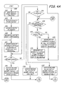
- FIGs. 4A and 4B An iterative algorithm is depicted in FIGs. 4A and 4B that over the ICD lifetime develops the database depicted in the look-up Tables 1, 2, and 3 of FIG. 5 .
- the database Tables 1, 2, and 3 of successful and unsuccessful ATP regimens correlated to the measured exploratory RCL Em depicted in FIG. 5 is developed over time starting with (and periodically reverting to) application of the physician programmed baseline ATP regimens, determination and database storage of their success or failure in terminating VT episodes, and delivering successive ones of the "N" ATP regimens with ATP parameters varied from the ATP parameters of the programmed baseline ATP regimens.
- VT episode number "m" is illustrated in FIGS. 3A and 3B that is characterized by a sequence of high rate, spontaneously occurring, R-waves detected from the VSENSE events (shortened to "VS" in FIGs. 3A and 3B ) separated by intrinsic tachycardia cycle lengths CL T .
- Such VT episodes are detected employing one of the above-described VT detection algorithms.
- An exploratory ATP E sequence of P 3, in this example, exploratory pacing pulses P E1 , P E2 , and P E3 are delivered at a pulse energy that captures the ventricles and elicits pace triggered R-waves.
- the ATP E sequence is selected in number of ATP E pulses and the ATP E pacing rate, set by exploratory cycle length CL E , to ensure that the intrinsic VT is overdriven or suppressed and that at least the last ATP E pacing pulse P E3 is likely to interact with the VT circuit. However, these parameters (number P and cycle length CL E ) of the ATP E sequence are selected to not likely terminate the VT episode.
- the exploratory RCL Em is then measured from the last ATP E pacing pulse P E3 to the VSENSE detection of the next intrinsic R-wave.
- a baseline ATP regimen can be delivered if the current measured RCL Em matches a stored exploratory RCL in look-up Table 3 or if there are no matches with any stored exploratory RCLs in any of look-up Tables 1 to 3.
- a "match" of the current exploratory RCL with one of the stored exploratory RCLs in Tables 1 to 3 is declared if any difference is within a certain defined tolerance, e.g. +/-10m, for example.
- the exploratory RCL E that is measured after delivery of the exploratory ATP sequence following detection of a VT episode is compared first to each stored exploratory RCL associated with a delivered ATP regimen in look-up Table 3, second to each stored exploratory RCL associated with a delivered ATP regimen in look-up Table 1, and third to each stored exploratory RCL associated with a delivered ATP regimen in look-up Table 2.
- the particular details of the comparisons are set forth below in reference to FIGs. 4A and 4B .
- a successful ATP regimen of Table 1 is selected to be delivered if: (1) it is correlated to a stored exploratory RCL Em in Table 1 that matches the current measured exploratory RCL Em ; and (2) it possesses a certain "ATP Historical Efficacy" that is also stored in Table 1 and updated depending upon a determination of success or failure each time that ATP regimen is formulated (selected) and delivered.
- ATP Historical Efficacy that is also stored in Table 1 and updated depending upon a determination of success or failure each time that ATP regimen is formulated (selected) and delivered.
- Table 1 may have more than one ATP regimens associated with VT episodes that exhibit the same (within the defined tolerances) measured exploratory RCL.
- An ATP sequence is formulated in a manner described further below if there are no matches between the currently measured exploratory RCL and any of the RCL E ", values stored in Tables 3 and 1, but a match is made with an RCL E value stored in Table 2.
- an ATP regimen comprising of "p" ATP pacing pulses, P 1 through P P , each having a pulse energy likely to capture the heart at a pacing rate dictated by an overdrive cycle length CL mn (where "n” is 1 st, 2nd or N th ATP therapy delivered following measurement of RCL Em of the m th VT episode).
- the first delivered ATP regimen is determined to be successful in terminating the VT as evidenced by the measured intrinsic cycle lengths between the VSENSE events (designated CL NSR ) that are longer than a VT threshold cycle length.
- CL NSR the measured intrinsic cycle lengths between the VSENSE events
- the VT episode count "m" would be incremented and the delivered ATP regimen associated with the measured RCL Em would be stored in the look-up Table 1, if the combination is not already present in Table 1 If the combination is already stored in look-up Table 1, then the episode count "m” would not be incremented but the ATP Historical Efficacy for the particular ATP regimen would be increased, if less than 100%.
- the VT episode is not terminated by the first delivered ATP regimen as determined by the measurement and processing of the post-delivery VSENSE events and measurement and comparison of the intrinsic cycle lengths CL T to VT detection criterion. It is determined that the VT episode has not accelerated by comparison of the post-delivery CL T to the pre-delivery CL T . It is also assumed that maximum number (N) of ATP therapies allowed to be delivered for a VT episode is set to be 2 so that a second ATP regimen is delivered for this episode.
- the first ATP regimen delivered in FIG. 3B is formulated (selected) from Table 1.
- the first ATP regimen delivered in FIG. 3B had previously been found to be "successful” and stored in Table 1 in association with one of the stored exploratory RCL values, and the current measured RCL E depicted in FIG. 3B matched that stored value.
- the Historical Efficacy of that ATP regimen would be decreased in Table 1.
- the second delivered ATP regimen depicted in FIG. 3B is derived by simply selecting the next programmed baseline ATP regimen.
- the second delivered ATP regimen is depicted as successfully terminating the VT episode in this example of FIG. 3B and will be used to update the Table 1. If the second ATP is a failure, however, the information will be used to update the Table 2 and used to tailor subsequent ATP regimens (see below).
- the currently measured RCL E depicted in FIG. 3B matched one of the stored exploratory RCL values associated with an ATP regimen that had previously been found to be "unsuccessful" but not causing VT rate acceleration and stored in Table 2.
- the parameters of the first ATP regimen delivered in FIG. 3B are formulated from the stored RCL for the last two ATP regimens delivered when the same VT episode (as determined by the unique RCL E signature) was encountered previously.
- the new ATP regimen is obtained by incrementing the number of pulses by one or in general by a fixed programmable number but keeping the CL the same as n th VT regimen. If, however, the RCL for the two ATP regimens did not change by a threshold amount then the new ATP regimen is obtained by keeping the number of pulses same as the n th ATP regimen but making the new ATP regimen more aggressive (i.e. decrementing the CL by a programmable amount e.g. 20 ms or 5% VT CL etc).
- FIGs. 4A and 4B and the timing diagrams of FIGS 3A and 3B are intended to illustrate the functional operation of the algorithm of the present invention implemented into the exemplary ICD operating system 100, and should not be construed as reflective of a specific form of software, firmware and/or hardware necessary to practice the invention. It is believed that the particular form of software, firm ware or hardware will be determined primarily by the particular system architecture employed in the ICD or anti-tachycardia pacemaker and by the particular detection and therapy delivery methodologies that are employed. Providing software, firmware and/or hardware to accomplish the present invention in the context of any modem implantable anti-tachycardia pacemaker or ICD, given the disclosure herein, is well within the abilities of one of skill in the art.
- the satisfaction of VT detection criteria is followed by delivery of the exploratory ATP sequence (ATP E ) of pacing pulses that overdrive the VT but are not likely to terminate the VT episode.
- the exploratory RCL Em is measured following the last pacing pulse of the exploratory ATP E sequence.
- FIG. 4A illustrate the initial determination of such an exploratory RCL E upon satisfaction of VT detection criteria, the delivery of a programmed baseline ATP regimen in response to the detected VT episode, the delivery of "n" (at least one more) modified ATP n regimen(s) if the ATP regimen delivered during a pervious detection of the same episode is unsuccessful, and the accumulation of data associating the exploratory RCL Em with the successful or unsuccessful ATP regimen that is stored in memory in one of the tables (1, 2 and 3) of FIG. 5 .
- the steps S330 - S366 of FIG. 4B illustrate the use of successful or the avoidance of unsuccessful stored ATP regimens corresponding to stored exploratory RCL values that match (within defmed tolerances) exploratory RCL values that are determined in subsequent VT episodes.
- Steps S310 - S328 of FIG. 4A are reverted to in order to develop further modified ATP regimens when a current measured exploratory RCL Em does not match any stored exploratory RCLs associated in Table 1 with successful ATP regimen
- the ICD is implanted and programmed at start step S300, and the very first VT episode experienced by the patient is detected in step S302 employing any of the above-described VT detection criterion.
- the VT episode rate represented by CL T is also determined and temporarily stored for possible subsequent determination of VT rate acceleration.
- the unique VT episode count "m" is initialized to "1" in step S304.
- the exploratory ATP sequence is delivered in step S306, and the exploratory RCL Em is measured and temporarily stored in steps S308 for reference in later steps of the algorithm.
- step S310 a baseline ATP regimen of "p" pacing pulses at CL mn (CL of n th ATP sequence) is delivered, the delivered ATP regimen count “n” is set to "1", and the post-ATP regimen RCL mn is measured and temporarily stored for later use in the algorithm.
- step S362 of FIG. 4B it is necessary to revert from step S362 of FIG. 4B to the delivery of a baseline ATP regimen in accordance with step S310 and selectively follow the steps S312 - S328 as described further below.
- step S312 a determination of whether the delivered baseline ATP regimen is successful or unsuccessful is made. If success is achieved, then the exploratory RCL Em measured in step S308 is associated in step S314 with the ATP regimen (specifically the ATP regimen parameters comprising the number of delivered pacing pulses "p" and the cycle length) delivered in step S310 and stored in Table 1 and the ATP regimen Historical Efficacy of Table 1 is updated. The algorithm then advances to monitoring the VSENSE events to detect a subsequent VT episode in step S330 in FIG. 4B .
- the exploratory RCL Em measured in step S308 is associated in step S314 with the ATP regimen (specifically the ATP regimen parameters comprising the number of delivered pacing pulses "p" and the cycle length) delivered in step S310 and stored in Table 1 and the ATP regimen Historical Efficacy of Table 1 is updated.
- the algorithm then advances to monitoring the VSENSE events to detect a subsequent VT episode in step S330 in FIG. 4B .
- step S312 If success is not achieved as determined in step S312, then a comparison of the current VT episode rate to the VT episode rate stored in step S302 is made in step S316 to determine whether the VT has accelerated or not. If VT acceleration is determined to have occurred in step S316, then the RCL Em stored in step S308 is associated in step S313 with the delivered ATP regimen as having caused acceleration and stored in Table 3. The use of such a delivered ATP regimen causing acceleration to treat a future VT episode exhibiting the RCL E associated with that delivered ATP regimen is avoided in accordance with one aspect of the present invention. The algorithm then advances to step 340 to determine if a shock therapy should be delivered to terminate VT or successful ATP regimen be determined starting at a new baseline therapy (step 360).
- N 1 in this instance
- step S320 If it is determined in step S320 that another ATP regimen is allowed, then a comparison is made between the most recent RCL mn and the preceding RCL mn-1 measured for the same VT episode (step 324). If the RCL difference is greater than a threshold amount, RCL TH , then a subsequent ATP regimen is delivered that simply has more number of pulses (from, the n th ATP) while maintaining the same aggressiveness (i.e. cycle length, CL) as the previously delivered ATP (step 326). Alternatively, if the RCL difference is less than the threshold value, the new ATP has the same number of pulses but shorter CL by a programmable value OCL.
- the RCL for the 0 th ATP regimen i.e. exploratory sequence
- the baseline regimen are used to make decision to increment number of pulses or decrease CL for subsequently delivered ATP either during that particular detection of that episode or during a later detection of the same VT (i.e. VT having same exploratory RCL signature).
- steps S312 to S322 as described above are selectively repeated until one of step S312 or S316 is satisfied or it is determined in step S320 that no further ATP regimens can be delivered.
- the RCL mn and RCL nn-1 are stored in Table 2 (step 322) and are carried over for use in the next detected episode of the same VT. Consequently Table 2 consists of n rows each of which corresponds to a unique VT by virtue of a characteristic RCL Em .
- the next two columns of the table store RCLs for the n th and n-1 th failed ATP attempt.
- the parameters for the n th failed ATP regimen are stored in the last column and these ATP parameters are used to design ATP therapy for a subsequently detected episode of the same VT.
- the determination of whether a currently detected episode is same as one of the prestored VTs is made by comparing the exploratory RCL for the newly detected episode with RCL E s already stored in the Table 2 (step 348 in Fig. 4B ).
- the steps S330 - S366 of FIG. 4B and the steps S310 - S328 of FIG. 4A are selectively followed whenever a subsequent VT episode is detected in step S330.
- the exploratory ATP E sequence is delivered in step S332 upon detection of each subsequent VT episode in step S330, and the RCL Em is measured and temporarily stored in step S334.
- step S336 the value of the measured exploratory RCL Em is compared to the exploratory RCL values associated with unsuccessful ATP regimens that result in VT acceleration that are stored in Table 3. If there is a match as determined in step S338, then it is undesirable to retrieve and employ the associated ATP regimen.
- step S340 determines whether the immediate delivery of a C/D shock therapy in step S342 is preferred or if any further ATP regimens are to be delivered as determined in step S360.
- One or more (if necessary) C/D shocks are delivered in step S342, if either the immediate delivery is preferred as determined in step S340 or no further baseline ATP therapies are to be delivered as determined in step S360.
- the algorithm After VT termination and/or delivery of the last C/D shock in step S342, the algorithm returns to standby awaiting satisfaction of step S330. If a further baseline therapy is programmed as determined in step S362, then the next baseline therapy is loaded in step S362, and steps S310 - S328 are selectively followed.
- a comparison of the exploratory RCL measured in step S334 with the stored exploratory RCL values of look-up Table 1 is made in steps S344 and S346. If no match is found in step S338 between the exploratory RCL measured in step S334 and the stored exploratory RCL values of look-up Table 3, a match is attempted between RCL Em for the current episode and exploratory RCL stored in Table 1. If there is no match in step 346, then the exploratory RCL Em is matched with exploratory RCLs stored in Table 2 in steps S348 and S350.
- step S350 If no match is made in step S350, then the exploratory RCL measured in step S334 does not match any of the stored RCL values in any of the look-up Tables 1 - 3, and the unique VT episode count "m" is incremented in step S366.
- step S342 or steps S362 and S310 - S328 are followed, depending upon whether a further baseline ATP regimen is programmed in step S360. In the latter case, at least one more attempt is made to deliver an ATP regimen to terminate the VT episode and increment the database.
- step S350 the determination is again made in step S320 whether a further ATP regimen can be formulated and delivered. If no further ATP regimen can be formulated and delivered, then the above-described steps are followed in steps S322 and in step 342 to deliver the programmed C/D shock therapies. If a further ATP regimen can be formulated and delivered, then steps S324 - S328 are selectively followed to formulate and deliver the further ATP regimen as an iteration of a previously delivered unsuccessful ATP regimen. The success or failure of the formulated ATP regimen is then determined and data stored in the look-up Tables 1 - 3 selectively following steps S312 - S328 and steps branching therefrom again.
- step S346 if a match is made between the exploratory RCL measured in step S334 with the stored RCL values of look-up Table 1, then the Historical Efficacy of the matched ATP regimen is examined in step S352. If the Historical Efficacy (EFF HISTMAX ) does not exceed an efficacy threshold (EFF THRESH ), then the unique VT episode count "m" is incremented in step S366. Again, either step S342 or steps S362 and S310 - S328 are followed, depending upon whether a further baseline ATP regimen is programmed in step S360. In the latter case, at least one more ATP regimen is delivered to terminate the VT episode and increment the database.
- EPF HISTMAX an efficacy threshold
- step S352 If the EFF HISTMAX does exceed the EFF THRESH as determined in step S352, then the associated ATP regimen is retrieved from Table 1 and delivered in step S354. If the ATP regimen delivered in step S354 is successful as determined in step S356, then the Historical Efficacy of the ATP regimen is updated in step S364, and VSENSE events are monitored in step S330 to detect a further VT episode. If the ATP regimen delivered in step S354 is not successful as determined in step S356, then the Historical Efficacy of the ATP regimen is updated in step S358. In case the ATP is a failure, the determination of whether a further baseline ATP regimen is programmed is made in step S360.
- step S342 or steps S362 and S310 - S328 are followed, depending upon whether a further baseline ATP regimen is programmed in step S360. In the latter case, at least one more attempt is made to deliver an ATP regimen to terminate the VT episode and increment the database.
Landscapes
- Health & Medical Sciences (AREA)
- Cardiology (AREA)
- Heart & Thoracic Surgery (AREA)
- Engineering & Computer Science (AREA)
- Biomedical Technology (AREA)
- Nuclear Medicine, Radiotherapy & Molecular Imaging (AREA)
- Radiology & Medical Imaging (AREA)
- Life Sciences & Earth Sciences (AREA)
- Animal Behavior & Ethology (AREA)
- General Health & Medical Sciences (AREA)
- Public Health (AREA)
- Veterinary Medicine (AREA)
- Electrotherapy Devices (AREA)
Claims (15)
- Implantierbare medizinische Vorrichtung des Typs, der intrinsische Depolarisationen einer Herzkammer detektiert, eine Tachykardie-Episode detektiert und auf die detektierte Tachykardie einer Herzkammer durch Verabreichen von Antitachykardie-Schrittmachertherapien (ATP-Therapien) an die Herzkammer antwortet, ferner mit:einer Einrichtung (108), die betreibbar ist, um bei Detektion einer Tachykardie eine explorative ATP-Sequenz von Schrittmacherimpulsen an die Herzkammer zu verabreichen, um eine durch Schrittmachen bzw. Stimulierung bewirkte Depolarisation der Herzkammer bei Verabreichung wenigstens des letzten verabreichten ATP-Impulses hervorzurufen;einer Einrichtung (102), um die Rückkehrzykluslänge (RCL) zwischen dem letzten verabreichten Schrittmacherimpuls der explorativen bzw. exploratorischen ATP-Sequenz und der nächsten detektierten intrinsischen Depolarisation als eine gemessene explorative RCL zu messen;einer Formulierungseinrichtung (102), um eine ATP-Behandlung, die definierte ATP-Parameter besitzt, als eine Funktion der gemessenen explorativen RCL zu formulieren; undeiner Einrichtung (122), um die ATP-Behandlung zu verabreichen; wobei die implantierbare medizinische Vorrichtung dadurch gekennzeichnet ist, dass sie ferner enthält:eine Einrichtung, um zu bestimmen, ob die Tachykardie-Episode nach der Verabreichung der ATP-Behandlung endet;eine Klassifizierungseinrichtung, um die verabreichte ATP-Behandlung als eine erfolgreiche ATP-Behandlung in Zuordnung zu der gemessenen explorativen RCL zu klassifizieren, falls bestimmt wird, dass die Tachykardie-Episode endet; undeine Speichereinrichtung, um die erfolgreiche ATP-Behandlung in Zuordnung zu der gemessenen explorativen RCL in einer Datenbank in einem IMD-Speicher zu speichern; und wobei:die Formulierungseinrichtung ferner eine Einrichtung enthält, um die gemessene explorative RCL mit jeder gespeicherten RCL zu vergleichen und um eine erfolgreiche ATP-Behandlung aus der Datenbank wiederzugewinnen, wenn die gemessene explorative RCL mit einer gespeicherten RCL, die einer in der Datenbank gespeicherten erfolgreichen ATP-Behandlung zugeordnet ist, übereinstimmt.
- Implantierbare medizinische Vorrichtung nach Anspruch 1, wobei:die Klassifizierungseinrichtung betreibbar ist, um die verabreichte ATP-Behandlung als eine nicht erfolgreiche ATP-Behandlung in Zuordnung zu der gemessenen explorativen RCL zu klassifizieren, falls bestimmt wird, dass die Tachykardie-Episode nicht geendet hat; unddie Speichereinrichtung betreibbar ist, um die nicht erfolgreiche ATP-Behandlung in Zuordnung zu der gemessenen explorativen RCL im IMD-Speicher zu speichern,wodurch im IMD-Speicher eine Datenbank akkumuliert wird, die erfolgreiche und nicht erfolgreiche ATP-Behandlungen enthält, die gespeicherten explorativen RCLs zugeordnet sind.
- Implantierbare medizinische Vorrichtung nach Anspruch 2, ferner mit:einer Einrichtung, die betreibbar ist, um bei Detektion einer Tachykardie die Vor-ATP-Rate der Tachykardie vor der Verabreichung der explorativen Behandlung zu bestimmen; undeiner Einrichtung, die betreibbar ist, um dann, wenn bestimmt wird, dass die Tachykardie-Episode nicht geendet hat, die Nach-ATP-Rate der Tachykardie nach der Verabreichung der ATP-Behandlung zu bestimmen; und wobei:die Klassifizierungseinrichtung betreibbar ist, um die verabreichte ATP-Behandlung als eine nicht erfolgreiche, beschleunigende ATP-Behandlung in Zuordnung zu der bestimmten RCL zu klassifizieren, falls die Nach-ATP-Rate größer ist als die Vor-ATP-Rate, und um die verabreichte ATP-Behandlung als eine nicht erfolgreiche, nicht beschleunigende ATP-Behandlung in Zuordnung zu der bestimmten RCL zu klassifizieren, falls die Vor-ATP-Rate größer oder gleich der Nach-ATP-Rate ist; und wobei die Speichereinrichtung betreibbar ist, um die nicht erfolgreiche, beschleunigende ATP-Behandlung in Zuordnung zu der gemessenen explorativen RCL oder die nicht erfolgreiche, nicht beschleunigende ATP-Behandlung in Zuordnung zu der gemessenen explorativen RCL im IMD-Speicher zu speichern.
- Implantierbare medizinische Vorrichtung nach Anspruch 2, ferner mit:einer Einrichtung, um eine historische Wirksamkeit jeder klassifizierten erfolgreichen ATP-Behandlung, die einer gespeicherten explorativen RCL zugeordnet ist, zu bestimmen und zu speichern, wobei die Wirksamkeitseinordnung das Verhältnis der Anzahl erfolgreicher Beendigungen einer Tachykardie durch die ATP-Behandlung zu der Anzahl nicht erfolgreicher, nicht beschleunigender Beendigungen durch dieselbe ATP-Behandlung repräsentiert; und wobei:die Formulierungseinrichtung ferner eine Einrichtung enthält, um eine erfolgreiche ATP-Behandlung mit der höchsten historischen Wirksamkeit unter den gespeicherten erfolgreichen ATP-Behandlungen, die derselben gespeicherten explorativen RCL zugeordnet sind, die mit der gemessenen explorativen RCL übereinstimmt, auszuwählen.
- Implantierbare medizinische Vorrichtung nach einem vorhergehenden Anspruch, ferner mit:einer Beendigungsbestimmungseinrichtung, um zu bestimmen, ob die Tachykardie-Episode durch Verabreichung der ATP-Behandlung geendet hat; undeiner Einrichtung, die betreibbar ist, um dann, wenn bestimmt wird, dass die Tachykardie-Episode geendet hat, die verabreichte ATP-Behandlung als eine erfolgreiche ATP-Behandlung in Zuordnung zu der gemessenen explorativen RCL im IMD-Speicher zu speichern;und wobei die Formulierungseinrichtung ferner enthält:eine Einrichtung, um die gemessene explorative RCL mit irgendwelchen früher gemessenen, gespeicherten explorativen RCLs, die im IMD-Speicher gespeichert sind, zu vergleichen; undeine Einrichtung, um die erfolgreiche ATP-Behandlung, die der gespeicherten explorativen RCL zugeordnet ist, aus der Datenbank wiederzugewinnen, falls die explorative RCL mit der gespeicherten explorativen RCL übereinstimmt.
- Implantierbare medizinische Vorrichtung nach Anspruch 5, ferner mit:einer Speichereinrichtung, um die verabreichte ATP-Behandlung als eine nicht erfolgreiche ATP-Behandlung in Zuordnung zu der gemessenen explorativen RCL in dem IMD-Speicher zu speichern, falls durch die Beendigungsbestimmungseinrichtung bestimmt wird, dass die Tachykardie-Episode nicht geendet hat;wodurch eine Datenbank im IMD-Speicher akkumuliert wird, die erfolgreiche und nicht erfolgreiche ATP-Behandlungen enthält, wovon jede einer gespeicherten explorativen RCL zugeordnet ist.
- Implantierbare medizinische Vorrichtung nach Anspruch 6, ferner mit:einer Tachykardieraten-Bestimmungseinrichtung, um die Vor-ATP-Rate der Tachykardie vor der Verabreichung der explorativen Behandlung und die Nach-ATP-Rate der Tachykardie, die der Verabreichung der ATP-Behandlung folgt, zu bestimmen;wobei die Speichereinrichtung betreibbar ist, um die verabreichte ATP-Behandlung als eine nicht erfolgreiche, nicht beschleunigende ATP-Behandlung in Zuordnung zu der gemessenen explorativen RCL im IMD-Speicher zu speichern, falls die Nach-ATP-Rate kleiner oder im Wesentlichen gleich der Vor-ATP-Rate ist, und betreibbar ist, um die verabreichte ATP-Behandlung als eine nicht erfolgreiche, beschleunigende ATP-Behandlung in Zuordnung zu der gemessenen explorativen RCL im IMD-Speicher zu speichern, falls die Nach-ATP-Rate um einen vorgegebenen Betrag größer ist als die Vor-ATP-Rate,wodurch im IMD-Speicher eine Datenbank akkumuliert wird, die erfolgreiche und nicht erfolgreiche ATP-Behandlungen, wovon jede einer gespeicherten explorativen RCL zugeordnet ist, enthält.
- Implantierbare medizinische Vorrichtung nach Anspruch 7, wobei die Formulierungseinrichtung ferner enthält:eine Einrichtung, um die gemessene explorative RCL mit den gespeicherten explorativen RCLs, die im IMD-Speicher gespeichert sind, zu vergleichen; undeine Einrichtung, um die ATP-Parameter der ATP-Behandlung, die verabreicht werden soll, als eine Grundlinien-ATP-Therapie zu formulieren, falls der gemessene ATP-Parameter mit einer gespeicherten explorativen RCL, die einer nicht erfolgreichen, beschleunigenden ATP-Behandlung zugeordnet ist, übereinstimmt.
- Implantierbare medizinische Vorrichtung nach Anspruch 6, ferner mit:einer Einrichtung, um eine ATP-Behandlungs-RCL von dem letzten verabreichten ATP-Behandlungs-Schrittmacherimpuls zu der nächsten detektierten intrinsischen Depolarisation zu messen;einer Tachykardieraten-Bestimmungseinrichtung, um die Vor-ATP-Rate der Tachykardie vor der Verabreichung der explorativen Behandlung und die Nach-ATP-Rate der Tachykardie, die der Verabreichung der ATP-Behandlung folgt, zu bestimmen;und wobei die Speichereinrichtung betreibbar ist, um die verabreichte ATP-Behandlung als eine nicht erfolgreiche, nicht beschleunigende ATP-Behandlung in Zuordnung zu der gemessenen explorativen RCL und der ATP-Behandlungs-RCL im IMD-Speicher zu speichern, falls die Nach-ATP-Rate kleiner oder im Wesentlichen gleich der Vor-ATP-Rate ist.
- Implantierbare medizinische Vorrichtung nach Anspruch 9, wobei die Formulierungseinrichtung ferner eine Einrichtung enthält, die betreibbar ist, um dann, wenn der gemessene ATP-Parameter mit einer gespeicherten explorativen RCL, die einer nicht erfolgreichen, nicht beschleunigenden ATP-Behandlung zugeordnet ist, übereinstimmt, die ATP-Parameter der zu verabreichenden ATP-Behandlung als eine Iteration der ATP-Parameter der nicht erfolgreichen, nicht beschleunigenden ATP-Behandlung und ihrer zugeordneten ATP-Behandlungs-RCL zu formulieren.
- Implantierbare medizinische Vorrichtung nach Anspruch 10, wobei die ATP-Parameter die ATP-Zykluslänge und eine Anzahl von ATP-Impulsen enthalten und die Formulierungseinrichtung ferner eine Einrichtung enthält, um die ATP-Zykluslänge und/oder die Anzahl von ATP-Impulsen als Funktion des Vergleichs der ATP-Behandlungs-RCL mit der gemessenen explorativen RCL einzustellen.
- Implantierbare medizinische Vorrichtung nach Anspruch 11, wobei das Einstellen das Inkrementieren der Anzahl von ATP-Impulsen oder das Dekrementieren der ATP-Zykluslänge enthält, falls die ATP-Behandlungs-RCL die gemessene explorative RCL um einen vorgegebenen Betrag übersteigt.
- Implantierbare medizinische Vorrichtung nach Anspruch 12, wobei das Einstellen das jeweils Andere des Inkrementierens der Anzahl von ATP-Impulsen bzw. des Dekrementierens der ATP-Zykluslänge enthält, falls die ATP-Behandlungs-RCL die gemessene explorative RCL nicht um einen vorgegebenen Betrag übersteigt.
- Implantierbare medizinische Vorrichtung nach Anspruch 1, ferner mit:einer Einrichtung, die betreibbar ist, um dann, wenn bestimmt wird, dass die Tachykardie-Episode geendet hat, die verabreichte ATP-Behandlung als erfolgreich zu klassifizieren und um eine historische Wirksamkeit der verabreichten ATP-Behandlung zu inkrementieren und um die verabreichte ATP-Behandlung als eine erfolgreiche ATP-Behandlung in Zuordnung zu der historischen Wirksamkeit und der gemessenen explorativen RCL im IMD-Speicher zu speichern;und wobei die Formulierungseinrichtung ferner enthält:eine Einrichtung, die betreibbar ist, um dann, wenn die gemessene explorative RCL mit mehr als einer gespeicherten explorativen RCL übereinstimmt, die gespeicherten historischen Wirksamkeiten zu vergleichen und um die erfolgreiche ATP-Behandlung mit der höchsten gespeicherten historischen Wirksamkeit, die der gespeicherten explorativen RCL zugeordnet ist, aus der Datenbank wiederzugewinnen, um sie zu verabreichen.
- Implantierbare medizinische Vorrichtung nach Anspruch 14, ferner mit:einer Einrichtung, um die historische Wirksamkeit der gespeicherten erfolgreichen ATP-Behandlung zu dekrementieren, falls die verabreichte ATP-Behandlung eine früher gespeicherte erfolgreiche ATP-Behandlung enthält und die Tachykardie-Episode nicht beendet hat; undeiner Einrichtung, um die verabreichte ATP-Behandlung als eine nicht erfolgreiche ATP-Behandlung in Zuordnung zu der gemessenen explorativen RCL im IMD-Speicher zu speichern, falls die verabreichte ATP-Behandlung keine früher gespeicherte erfolgreiche ATP-Behandlung enthält,wodurch im IMD-Speicher eine Datenbank akkumuliert wird, die erfolgreiche und nicht erfolgreiche ATP-Behandlungen, wovon jede einer gespeicherten explorativen RCL zugeordnet ist, enthält.
Applications Claiming Priority (2)
| Application Number | Priority Date | Filing Date | Title |
|---|---|---|---|
| US10/672,229 US7392082B2 (en) | 2003-09-26 | 2003-09-26 | Inter-episode implementation of closed loop ATP |
| PCT/US2004/030882 WO2005030324A1 (en) | 2003-09-26 | 2004-09-22 | Inter-episode implementation of closed loop atp |
Publications (2)
| Publication Number | Publication Date |
|---|---|
| EP1673141A1 EP1673141A1 (de) | 2006-06-28 |
| EP1673141B1 true EP1673141B1 (de) | 2011-06-15 |
Family
ID=34376309
Family Applications (1)
| Application Number | Title | Priority Date | Filing Date |
|---|---|---|---|
| EP04784669A Expired - Lifetime EP1673141B1 (de) | 2003-09-26 | 2004-09-22 | Zwischen episoden bezogene implementierung einer durch gechlossene regelschleife geregelten atp-stimulation |
Country Status (5)
| Country | Link |
|---|---|
| US (1) | US7392082B2 (de) |
| EP (1) | EP1673141B1 (de) |
| JP (1) | JP4684227B2 (de) |
| CA (1) | CA2539248A1 (de) |
| WO (1) | WO2005030324A1 (de) |
Families Citing this family (25)
| Publication number | Priority date | Publication date | Assignee | Title |
|---|---|---|---|---|
| GB2413082A (en) * | 2004-04-14 | 2005-10-19 | Patrick Schauerte | Implantable cardioverter-defibrillator for treating tachycardia |
| US7515960B2 (en) | 2005-03-31 | 2009-04-07 | Medtronic, Inc. | Method and apparatus to terminate ventricular tachycardia via pacing |
| US8055340B2 (en) * | 2005-05-05 | 2011-11-08 | Cardiac Pacemakers, Inc. | Method and device for comprehensive anti-tachyarrhythmia therapy |
| US7751887B1 (en) * | 2006-04-28 | 2010-07-06 | Pacesetter, Inc. | Tiered antitachycardia pacing and pre-pulsing therapy |
| US7729763B2 (en) * | 2006-05-18 | 2010-06-01 | Medtronic, Inc. | Post long pause overdrive pacing in response to atrial tachyarrythmia episode |
| US7801608B2 (en) * | 2006-06-05 | 2010-09-21 | Cardiac Pacemakers, Inc. | Method and apparatus for closed-loop control of anti-tachyarrhythmia pacing using hemodynamic sensor |
| US8076305B2 (en) * | 2006-11-30 | 2011-12-13 | Medtronic, Inc. | Biological pacemakers including mutated hyperpolarization-activated cyclic nucleotide-gated (HCN) channels |
| US8437849B2 (en) * | 2007-01-30 | 2013-05-07 | Cardiac Pacemakers, Inc. | Method and apparatus for atrial pacing during tachyarrhythmia |
| US7873414B2 (en) * | 2007-04-17 | 2011-01-18 | Cardiac Pacemakers, Inc. | Patient characteristic based adaptive anti-tachy pacing programming |
| WO2009089518A2 (en) * | 2008-01-11 | 2009-07-16 | Massachusetts Institute Of Technology | Endovascular platforms for the differential targeting of molecules to vessel wall and vessel lumen |
| DE102008002331A1 (de) * | 2008-06-10 | 2009-12-17 | Biotronik Crm Patent Ag | Elektrotherapieeinrichtung zur Behandlung tachykarder Rythmusstörungen eines Herzens |
| US8064999B2 (en) * | 2009-01-30 | 2011-11-22 | Medtronic, Inc. | Distance-based analysis of return cycles for tachycardia discrimination |
| US8527047B2 (en) * | 2009-05-11 | 2013-09-03 | Cardiac Pacemakers, Inc. | Artificial conduction pathways in tachyarrhythmia |
| US20110144028A1 (en) * | 2009-12-11 | 2011-06-16 | Vinod Sharma | Modulating cellular electrophysiology |
| US8639323B2 (en) | 2010-11-01 | 2014-01-28 | Medtronic, Inc. | System and apparatus to monitor biopacemaker maturation |
| US9526908B2 (en) | 2014-04-01 | 2016-12-27 | Medtronic, Inc. | Method and apparatus for discriminating tachycardia events in a medical device |
| US10376705B2 (en) | 2014-04-01 | 2019-08-13 | Medtronic, Inc. | Method and apparatus for discriminating tachycardia events in a medical device |
| US9808640B2 (en) | 2014-04-10 | 2017-11-07 | Medtronic, Inc. | Method and apparatus for discriminating tachycardia events in a medical device using two sensing vectors |
| US9352165B2 (en) | 2014-04-17 | 2016-05-31 | Medtronic, Inc. | Method and apparatus for verifying discriminating of tachycardia events in a medical device having dual sensing vectors |
| US10278601B2 (en) | 2014-04-24 | 2019-05-07 | Medtronic, Inc. | Method and apparatus for selecting a sensing vector configuration in a medical device |
| US10244957B2 (en) | 2014-04-24 | 2019-04-02 | Medtronic, Inc. | Method and apparatus for selecting a sensing vector configuration in a medical device |
| US9795312B2 (en) | 2014-04-24 | 2017-10-24 | Medtronic, Inc. | Method and apparatus for adjusting a blanking period for selecting a sensing vector configuration in a medical device |
| US10252067B2 (en) | 2014-04-24 | 2019-04-09 | Medtronic, Inc. | Method and apparatus for adjusting a blanking period during transitioning between operating states in a medical device |
| US9610025B2 (en) | 2014-07-01 | 2017-04-04 | Medtronic, Inc. | Method and apparatus for verifying discriminating of tachycardia events in a medical device having dual sensing vectors |
| JP6795501B2 (ja) * | 2014-07-29 | 2020-12-02 | カルディオフロー テクノロジーズ リミテッド ライアビリティー カンパニーCardioflow Technologies,LLC | 抗頻拍ペーシング(atp)の最適化システム及び方法 |
Family Cites Families (6)
| Publication number | Priority date | Publication date | Assignee | Title |
|---|---|---|---|---|
| US4312356A (en) * | 1979-03-07 | 1982-01-26 | George Edgar Sowton | Pacemakers for tachycardia control |
| US6167308A (en) * | 1999-04-09 | 2000-12-26 | Medtronic, Inc. | Closed loop ATP |
| US6393316B1 (en) * | 1999-05-12 | 2002-05-21 | Medtronic, Inc. | Method and apparatus for detection and treatment of cardiac arrhythmias |
| US6400986B1 (en) * | 2000-04-10 | 2002-06-04 | Cardiac Pacemakers, Inc. | Adaptive anti-tachycardia therapy apparatus and method |
| US6775572B2 (en) * | 2001-10-25 | 2004-08-10 | Cardiac Pacemakers, Inc. | Method and system for automatic anti-tachycardia pacing |
| US7149577B2 (en) * | 2002-12-02 | 2006-12-12 | Medtronic, Inc. | Apparatus and method using ATP return cycle length for arrhythmia discrimination |
-
2003
- 2003-09-26 US US10/672,229 patent/US7392082B2/en not_active Expired - Lifetime
-
2004
- 2004-09-22 CA CA002539248A patent/CA2539248A1/en not_active Abandoned
- 2004-09-22 WO PCT/US2004/030882 patent/WO2005030324A1/en not_active Ceased
- 2004-09-22 JP JP2006528103A patent/JP4684227B2/ja not_active Expired - Fee Related
- 2004-09-22 EP EP04784669A patent/EP1673141B1/de not_active Expired - Lifetime
Also Published As
| Publication number | Publication date |
|---|---|
| US7392082B2 (en) | 2008-06-24 |
| US20050070966A1 (en) | 2005-03-31 |
| JP4684227B2 (ja) | 2011-05-18 |
| CA2539248A1 (en) | 2005-04-07 |
| EP1673141A1 (de) | 2006-06-28 |
| JP2007522828A (ja) | 2007-08-16 |
| WO2005030324A1 (en) | 2005-04-07 |
Similar Documents
| Publication | Publication Date | Title |
|---|---|---|
| EP1673141B1 (de) | Zwischen episoden bezogene implementierung einer durch gechlossene regelschleife geregelten atp-stimulation | |
| EP1501592B1 (de) | Verfahren und vorrichtung zur verzögerten behandlung einer ventrikulären tachykardie | |
| US7167747B2 (en) | Identification of oversensing using sinus R-wave template | |
| EP0891207B1 (de) | Egm aufzeichnungssystem für implantierbare medizinische vorrichtung | |
| US7333855B2 (en) | Method and apparatus for determining oversensing in a medical device | |
| US7266409B2 (en) | Method and apparatus for determining oversensing in a medical device | |
| JP4262596B2 (ja) | 埋め込み可能医療デバイスにおいて高電圧および抗頻脈ペーシング治療の送出を制御する方法および装置 | |
| US20080161872A1 (en) | Method and apparatus for reducing inappropriate detection of lead-related noise | |
| US9480844B2 (en) | Method and apparatus for reducing noise in a medical device | |
| US20040260350A1 (en) | Automatic EGM amplitude measurements during tachyarrhythmia episodes | |
| US7245968B1 (en) | Implantable cardiac device providing rapid pacing T wave alternan pattern detection and method | |
| US20040210256A1 (en) | Methods and apparatus for decreasing incidences of early recurrence of atrial fibrillation | |
| US20050245975A1 (en) | Method and apparatus for controlling delivery of pacing pulses in response to increased ectopic frequency |
Legal Events
| Date | Code | Title | Description |
|---|---|---|---|
| PUAI | Public reference made under article 153(3) epc to a published international application that has entered the european phase |
Free format text: ORIGINAL CODE: 0009012 |
|
| 17P | Request for examination filed |
Effective date: 20060424 |
|
| AK | Designated contracting states |
Kind code of ref document: A1 Designated state(s): CH DE FR LI NL SE |
|
| DAX | Request for extension of the european patent (deleted) | ||
| RBV | Designated contracting states (corrected) |
Designated state(s): CH DE FR LI NL SE |
|
| RAP3 | Party data changed (applicant data changed or rights of an application transferred) |
Owner name: MEDTRONIC, INC. |
|
| 17Q | First examination report despatched |
Effective date: 20090112 |
|
| GRAP | Despatch of communication of intention to grant a patent |
Free format text: ORIGINAL CODE: EPIDOSNIGR1 |
|
| GRAS | Grant fee paid |
Free format text: ORIGINAL CODE: EPIDOSNIGR3 |
|
| GRAA | (expected) grant |
Free format text: ORIGINAL CODE: 0009210 |
|
| AK | Designated contracting states |
Kind code of ref document: B1 Designated state(s): CH DE FR LI NL SE |
|
| REG | Reference to a national code |
Ref country code: CH Ref legal event code: EP |
|
| REG | Reference to a national code |
Ref country code: DE Ref legal event code: R096 Ref document number: 602004033108 Country of ref document: DE Effective date: 20110721 |
|
| REG | Reference to a national code |
Ref country code: NL Ref legal event code: VDEP Effective date: 20110615 |
|
| PG25 | Lapsed in a contracting state [announced via postgrant information from national office to epo] |
Ref country code: SE Free format text: LAPSE BECAUSE OF FAILURE TO SUBMIT A TRANSLATION OF THE DESCRIPTION OR TO PAY THE FEE WITHIN THE PRESCRIBED TIME-LIMIT Effective date: 20110615 |
|
| PG25 | Lapsed in a contracting state [announced via postgrant information from national office to epo] |
Ref country code: NL Free format text: LAPSE BECAUSE OF FAILURE TO SUBMIT A TRANSLATION OF THE DESCRIPTION OR TO PAY THE FEE WITHIN THE PRESCRIBED TIME-LIMIT Effective date: 20110615 |
|
| PLBE | No opposition filed within time limit |
Free format text: ORIGINAL CODE: 0009261 |
|
| STAA | Information on the status of an ep patent application or granted ep patent |
Free format text: STATUS: NO OPPOSITION FILED WITHIN TIME LIMIT |
|
| REG | Reference to a national code |
Ref country code: CH Ref legal event code: PL |
|
| 26N | No opposition filed |
Effective date: 20120316 |
|
| REG | Reference to a national code |
Ref country code: DE Ref legal event code: R097 Ref document number: 602004033108 Country of ref document: DE Effective date: 20120316 |
|
| PG25 | Lapsed in a contracting state [announced via postgrant information from national office to epo] |
Ref country code: CH Free format text: LAPSE BECAUSE OF NON-PAYMENT OF DUE FEES Effective date: 20110930 Ref country code: LI Free format text: LAPSE BECAUSE OF NON-PAYMENT OF DUE FEES Effective date: 20110930 |
|
| PGFP | Annual fee paid to national office [announced via postgrant information from national office to epo] |
Ref country code: DE Payment date: 20130927 Year of fee payment: 10 |
|
| PGFP | Annual fee paid to national office [announced via postgrant information from national office to epo] |
Ref country code: FR Payment date: 20130919 Year of fee payment: 10 |
|
| REG | Reference to a national code |
Ref country code: DE Ref legal event code: R119 Ref document number: 602004033108 Country of ref document: DE |
|
| REG | Reference to a national code |
Ref country code: DE Ref legal event code: R119 Ref document number: 602004033108 Country of ref document: DE Effective date: 20150401 |
|
| REG | Reference to a national code |
Ref country code: FR Ref legal event code: ST Effective date: 20150529 |
|
| PG25 | Lapsed in a contracting state [announced via postgrant information from national office to epo] |
Ref country code: DE Free format text: LAPSE BECAUSE OF NON-PAYMENT OF DUE FEES Effective date: 20150401 |
|
| PG25 | Lapsed in a contracting state [announced via postgrant information from national office to epo] |
Ref country code: FR Free format text: LAPSE BECAUSE OF NON-PAYMENT OF DUE FEES Effective date: 20140930 |