EP1672966A2 - Plasma jet systems and methods - Google Patents
Plasma jet systems and methods Download PDFInfo
- Publication number
- EP1672966A2 EP1672966A2 EP05257637A EP05257637A EP1672966A2 EP 1672966 A2 EP1672966 A2 EP 1672966A2 EP 05257637 A EP05257637 A EP 05257637A EP 05257637 A EP05257637 A EP 05257637A EP 1672966 A2 EP1672966 A2 EP 1672966A2
- Authority
- EP
- European Patent Office
- Prior art keywords
- plasma
- housing
- flow
- electric field
- jet system
- Prior art date
- Legal status (The legal status is an assumption and is not a legal conclusion. Google has not performed a legal analysis and makes no representation as to the accuracy of the status listed.)
- Withdrawn
Links
Images


Classifications
-
- B—PERFORMING OPERATIONS; TRANSPORTING
- B64—AIRCRAFT; AVIATION; COSMONAUTICS
- B64C—AEROPLANES; HELICOPTERS
- B64C23/00—Influencing air flow over aircraft surfaces, not otherwise provided for
- B64C23/005—Influencing air flow over aircraft surfaces, not otherwise provided for by other means not covered by groups B64C23/02 - B64C23/08, e.g. by electric charges, magnetic panels, piezoelectric elements, static charges or ultrasounds
-
- B—PERFORMING OPERATIONS; TRANSPORTING
- B64—AIRCRAFT; AVIATION; COSMONAUTICS
- B64C—AEROPLANES; HELICOPTERS
- B64C27/00—Rotorcraft; Rotors peculiar thereto
- B64C27/04—Helicopters
- B64C27/12—Rotor drives
- B64C27/16—Drive of rotors by means, e.g. propellers, mounted on rotor blades
- B64C27/18—Drive of rotors by means, e.g. propellers, mounted on rotor blades the means being jet-reaction apparatus
-
- F—MECHANICAL ENGINEERING; LIGHTING; HEATING; WEAPONS; BLASTING
- F03—MACHINES OR ENGINES FOR LIQUIDS; WIND, SPRING, OR WEIGHT MOTORS; PRODUCING MECHANICAL POWER OR A REACTIVE PROPULSIVE THRUST, NOT OTHERWISE PROVIDED FOR
- F03H—PRODUCING A REACTIVE PROPULSIVE THRUST, NOT OTHERWISE PROVIDED FOR
- F03H1/00—Using plasma to produce a reactive propulsive thrust
- F03H1/0037—Electrostatic ion thrusters
- F03H1/0062—Electrostatic ion thrusters grid-less with an applied magnetic field
-
- F—MECHANICAL ENGINEERING; LIGHTING; HEATING; WEAPONS; BLASTING
- F03—MACHINES OR ENGINES FOR LIQUIDS; WIND, SPRING, OR WEIGHT MOTORS; PRODUCING MECHANICAL POWER OR A REACTIVE PROPULSIVE THRUST, NOT OTHERWISE PROVIDED FOR
- F03H—PRODUCING A REACTIVE PROPULSIVE THRUST, NOT OTHERWISE PROVIDED FOR
- F03H1/00—Using plasma to produce a reactive propulsive thrust
- F03H1/0087—Electro-dynamic thrusters, e.g. pulsed plasma thrusters
-
- H—ELECTRICITY
- H05—ELECTRIC TECHNIQUES NOT OTHERWISE PROVIDED FOR
- H05H—PLASMA TECHNIQUE; PRODUCTION OF ACCELERATED ELECTRICALLY-CHARGED PARTICLES OR OF NEUTRONS; PRODUCTION OR ACCELERATION OF NEUTRAL MOLECULAR OR ATOMIC BEAMS
- H05H1/00—Generating plasma; Handling plasma
- H05H1/54—Plasma accelerators
-
- B—PERFORMING OPERATIONS; TRANSPORTING
- B64—AIRCRAFT; AVIATION; COSMONAUTICS
- B64C—AEROPLANES; HELICOPTERS
- B64C2230/00—Boundary layer controls
- B64C2230/12—Boundary layer controls by using electromagnetic tiles, fluid ionizers, static charges or plasma
-
- F—MECHANICAL ENGINEERING; LIGHTING; HEATING; WEAPONS; BLASTING
- F05—INDEXING SCHEMES RELATING TO ENGINES OR PUMPS IN VARIOUS SUBCLASSES OF CLASSES F01-F04
- F05D—INDEXING SCHEME FOR ASPECTS RELATING TO NON-POSITIVE-DISPLACEMENT MACHINES OR ENGINES, GAS-TURBINES OR JET-PROPULSION PLANTS
- F05D2270/00—Control
- F05D2270/01—Purpose of the control system
- F05D2270/17—Purpose of the control system to control boundary layer
- F05D2270/172—Purpose of the control system to control boundary layer by a plasma generator, e.g. control of ignition
-
- F—MECHANICAL ENGINEERING; LIGHTING; HEATING; WEAPONS; BLASTING
- F15—FLUID-PRESSURE ACTUATORS; HYDRAULICS OR PNEUMATICS IN GENERAL
- F15D—FLUID DYNAMICS, i.e. METHODS OR MEANS FOR INFLUENCING THE FLOW OF GASES OR LIQUIDS
- F15D1/00—Influencing flow of fluids
- F15D1/10—Influencing flow of fluids around bodies of solid material
- F15D1/12—Influencing flow of fluids around bodies of solid material by influencing the boundary layer
-
- Y—GENERAL TAGGING OF NEW TECHNOLOGICAL DEVELOPMENTS; GENERAL TAGGING OF CROSS-SECTIONAL TECHNOLOGIES SPANNING OVER SEVERAL SECTIONS OF THE IPC; TECHNICAL SUBJECTS COVERED BY FORMER USPC CROSS-REFERENCE ART COLLECTIONS [XRACs] AND DIGESTS
- Y02—TECHNOLOGIES OR APPLICATIONS FOR MITIGATION OR ADAPTATION AGAINST CLIMATE CHANGE
- Y02T—CLIMATE CHANGE MITIGATION TECHNOLOGIES RELATED TO TRANSPORTATION
- Y02T50/00—Aeronautics or air transport
- Y02T50/10—Drag reduction
Landscapes
- Engineering & Computer Science (AREA)
- Chemical & Material Sciences (AREA)
- Combustion & Propulsion (AREA)
- Physics & Mathematics (AREA)
- Plasma & Fusion (AREA)
- Mechanical Engineering (AREA)
- Aviation & Aerospace Engineering (AREA)
- General Engineering & Computer Science (AREA)
- Spectroscopy & Molecular Physics (AREA)
- Plasma Technology (AREA)
Abstract
Description
- This invention relates to plasma jet systems and methods, and in particular relates to plasma flow control.
- Active flow control involves modification of the turbulent structure of eddies in most complex flows with the intent to improve aerodynamic performance of air vehicle flight control and propulsion systems. Such capability can increase range and maneuverability, reduce acoustic loads, signature, weight, and cost. In some systems, a relatively small amount of high-momentum secondary fluid is used to enhance the naturally occurring instabilities of the main flow. For example, it is known to use active flow control in applications such as favorably influencing the flow over an aerodynamic surface, heating/cooling components, vectoring a primary fluid flow, and mixing fluids.
- One type of device that can be used for active flow control in subsonic systems is referred to as a zero-net-mass jet. A typical zero-net-mass jet actuator comprises a housing defining an internal chamber. An orifice is present in a wall of the housing. The actuator further includes a mechanism in or about the housing for periodically changing the volume within the internal chamber so that a series of fluid vortices are generated and projected in an external environment out from the orifice of the housing. Various volume changing mechanisms are known, for example a piston positioned in the jet housing to move so that fluid is moved in and out of the orifice during reciprocation of the piston, or a flexible diaphragm as a wall of the housing. The flexible diaphragm is typically actuated by a piezoelectric actuator or other appropriate means.
- Typically, a control system is utilized to create time-harmonic motion of the diaphragm. As the diaphragm moves into the chamber, decreasing the chamber volume, fluid is intermittently ejected from the chamber through the orifice. As a quantity of fluid passes through the orifice, the flow separates at the sharp edges of the orifice and creates a shear layer, which rolls up into a vortex sheet or ring. As each intermittent quantity of fluid is emitted, a separate vortical structure is generated creating a train of vortices moving away from the orifice. These vortices move away from the edges of the orifice under their own self-induced velocity. As the diaphragm moves outward with respect to the chamber, increasing the chamber volume, ambient fluid is drawn from all directions around the orifice into the chamber. Since the vortices are already removed from the edges of the orifice, they are not affected by the ambient fluid being entrained into the chamber. As the vortices travel away from the orifice, they synthesize a jet of fluid, a "zero-net-mass jet," through entrainment of the ambient fluid.
- However, piezoelectric diaphragms used to form zero-net-mass jets are generally unreliable due to moving parts and cause vibration in devices in which they are installed. Further, the amplitude, temperature, and frequency at which the diaphragms can operate is limited, with the result that piezoelectrically-driven zero-net-mass jets generate limited jet velocity and have little practical application in flows above approximately Mach 0.3.
- In physics and chemistry, plasma (also called an ionized gas) is an energetic state of matter in which some or all of the electrons in the outer atomic orbital rings have become separated from the atom. Excitation of a plasma requires partial ionization of neutral atoms and/or molecules of a medium. There are several ways to cause ionization including collisions of energetic particles, strong electric fields, and ionizing radiation. The energy for ionization may come from the heat of chemical or nuclear reactions of the medium, as in flames, for instance. Alternatively, already released charged particles may be accelerated by electric fields, generated electromagnetically or by radiation fields.
- There are two broad categories of plasma, hot plasmas and cold plasmas. In a hot plasma, full ionization takes place, and the ions and the electrons are in thermal equilibrium. A cold plasma (also known as a weakly ionized plasma) is one where only a small fraction of the atoms in a gas are ionized, and the electrons reach a very high temperature, whereas the ions remain at the ambient temperature. These plasmas can be created by using a high electric field, or through electron bombardment from an electron gun, and other means.
- According to the invention, there is provided a plasma jet system, comprising:
- a housing including one opening, wherein a partially ionized fluid is drawn into the opening;
- an electromagnetic accelerator configured to generate an electric field that accelerates the ionized fluid in the housing toward the opening in the housing, and to generate a magnetic field transverse to the electric field; and
- a controller coupled to modulate the electromagnetic accelerator, thereby causing the ionized fluid to form a pulsed plasma flow through the opening in the housing.
- A magnetic field is applied normal to the direction of the plasma vortex flow to mitigate the momentum of the electrons. The electrons slowed by the magnetic field can be collected and conducted to a location where they are re-inserted into the plasma vortex flow to maintain charge neutrality. The plasma jet system can be arranged to have no moving parts and no change in mass flow volume is required to create the plasma flow.
- The invention also provides a method comprising:
- accelerating an ionized fluid through an electric field in a housing, wherein the housing includes one opening and the electric field is oriented to accelerate the ionized fluid in the direction of the opening, thereby forming a plasma flow;
- generating a magnetic field transverse to the electric field, wherein the magnetic field decelerates electrons in the housing;
- collecting decelerated electrons; and
- transporting collected electrons to a location where the collected electrons are reinserted into the plasma flow.
- The invention also provides an apparatus comprising:
- an enclosure including one opening;
- an electric field generator operable to generate an electric field in the enclosure;
- a magnetic field generator operable to generate a magnetic field transverse to the electric field; and
- an ionized fluid source configured to provide ionized fluid in the enclosure, wherein the electric field is oriented to accelerate the ionized fluid toward the opening to generate a plasma jet.
- The foregoing has outlined rather broadly the features and technical advantages of embodiments of the present invention so that those skilled in the art may better understand the detailed description of embodiments of the invention that follows.
- Embodiments disclosed herein may be better understood, and their numerous objects, features, and advantages made apparent to those skilled in the art by referencing the accompanying drawings. The use of the same reference symbols in different drawings indicates similar or identical items.
- FIG. 1 is a diagram of an embodiment of a plasma jet system;
- FIGS. 2A and 2B show diagrams of another embodiment of a plasma jet system;
- FIGS. 3A and 3B show diagrams of another embodiment of a plasma jet system;
- FIG. 3C shows pairs of electrodes that can be activated and deactivated in series to generate an electric field to accelerate the plasma;
- FIG. 4 is a diagram of another embodiment of a plasma jet system;
- FIG. 5 is a diagram of an embodiment of a plasma injector;
- FIG. 6 is a diagram of an embodiment of a plasma jet system;
- FIG. 7A shows an embodiment of engine configured with plasma jets to vector fluid flow at the throat and/or exit areas of a nozzle;
- FIG. 7B shows an embodiment of engine configured with a duct to collect high-pressure air from flow at compressor section and provide the high-pressure flow to plasma jets;
- FIG. 8 shows an embodiment of a nozzle with plasma jets located to reduce the effective cross sectional area of nozzle throat;
- FIG. 9, an embodiment of nozzle is shown including thrust vectoring with plasma jets;
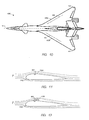
- FIG. 10 shows an embodiment of aircraft with plasma jets embedded in wings;
- FIGS. 11 and 12 shows an embodiment of an aerodynamic surface with plasma jets that are configured to change the effective aerodynamic shape of the surface; and
- FIG. 13 is a perspective view of an embodiment of self-propelled rotor in which a plasma jet can be utilized.
- What is desired is a fixed-volume zero-net-mass jet actuator with sufficient momentum and control authority that can be used to actively control high velocity flows in a variety of applications, such as engines, aerodynamic surfaces, mixing, and heating and cooling. Embodiments disclosed herein provide a plasma flow accelerated through an electric field to create a high speed, steady and/or high frequency pulsed plasma jet. The plasma jet can be configured to control flow without diverting a portion of the primary flow or requiring an auxiliary flow source.
- FIG. 1 shows a diagram of components that can be included in some embodiments of
plasma jet system 100, includingcontroller 102 coupled to operateplasma generator 104 andelectromagnetic accelerator 106.Plasma generator 104 can be configured to generate plasma inhousing 109.Cavity 110 inhousing 109 is formed with at least one opening.Electromagnetic accelerator 106 can be configured to generate an electric field E and a magnetic field B. The electric field E accelerates the plasma withincavity 110 toward an opening inhousing 109, while the electrons (indicated by "-" symbols) are accelerated in the opposite direction.Controller 102 modulates the frequency of the electric field E to cause ionized fluid (indicated by "+" symbols) to form a pulsedplasma vortex flow 112 through the opening. - The magnetic field B is applied normal to the direction of the plasma jet and creates a large force on the electrons. The force of magnetic field B mitigates the momentum of the electrons, which aids collection of the electrons by positive electrical terminal 114, such as a cathode. Positive terminal 114 can be coupled to a
conductive element 116 and configured to transport the electrons to a location downstream ofplasma vortex flow 112. Anegative terminal 118 such as an anode can be coupled to the other end ofconductive element 116 at a downstream location, where the electrons can be re-inserted intoplasma vortex flow 112 to help neutralize the charge offlow 112. Aswitch 120 can be coupled betweenconductive element 118 andcontroller 102.Controller 102 can be configured to receive information from one or more sensor(s) 122 regarding the characteristics offlow 112 at some downstream location, and control operation ofplasma generator 104 and electro-magnetic accelerator 106. -
Controller 102 can operateelectromagnetic accelerator 106 to provide a steady or a pulsed electric field. When a pulsed electric field is applied, a series of plasma vortices issue from an opening incavity 110, shown asplasma vortex flow 112. The strength and/or the pulse frequency of the electric field can be varied, depending on the force required fromplasma vortex flow 112. -
Controller 102 is typically implemented with a processing system that can be embodied in any suitable computing device(s) using any suitable combination of firmware, software, and/or hardware, such as microprocessors, Field Programmable Gate Arrays (FPGAs), Application Specific Integrated Circuit (ASICs), or other suitable devices.Controller 102 can be coupled to a power supply (not shown) to control power supplied toplasma generator 104 andelectromagnetic accelerator 106. Sensor(s) 122 can also provide information regarding the velocity, pressure, temperature, and other characteristics offlow 112 tocontroller 102 to operateelectromagnetic accelerator 106 andplasma generator 104. - Any suitable component or combination of components can be used for
controller 102,plasma generator 104,electromagnetic accelerator 106, positive terminal 114,negative terminal 118,conductor 116, and sensor(s) 122. For example,plasma generator 104 can be implemented by strong electric fields, electron beams, microwaves, and other phenomena and/or components capable of generating plasma.Electromagnetic accelerator 106 can be implemented with one or more suitable device(s) capable of generating an electrical field transverse to a magnetic field. - FIGS. 2A and 2B show perspective and side cut-away views, respectively, of an embodiment of another
plasma jet system 200 configured to generate acontinuous plasma jet 202.Controller 102 is coupled to regulateelectrodes 204 to generate an electric field that acceleratesflow 206 to formplasma jet 202.Electrodes 204 may be pulsed at one or more desired frequencies, and/or operated to apply a continuous electric field. The functions of plasma generator 104 (FIG. 1) can be performed byelectron beams 208 being injected intocavity 110 ofhousing 209 throughelectron beam windows 210 to ionizeflow 206.Windows 210 may be heated byelectron beams 208, and are of sufficient mechanical strength for the environment in whichhousing 209 is utilized. Any suitable type ofwindow 210 can be utilized. For example, in some configurations, thin metallic foils with passive cooling can be utilized forwindows 210. In other configurations withelectron beams 208 of relatively high current densities, either active cooling or plasma windows can be utilized.Windows 210 typically comprise only a portion of one or more walls ofhousing 209. For example, FIGS. 2A and 2B showswindows 210 as a series of rectangular strips in opposing sidewalls, however any suitable number, shape, and configuration ofwindows 210 can be used. The amount of plasma generated can also be varied, as required, by controlling generation of electron beams 208. - Housing 209 can be configured with one or
more magnet devices 212 that can be operated bycontroller 102 to create a transverse magnetic field normal to the direction of the electric field.Electrodes 204 andmagnet devices 212 together perform at least some of the functions of electromagnetic field generator 106 (FIG. 1).Magnetic devices 212 such as permanent magnets, electro-magnets, and/or superconducting magnets can be used to generate a magnetic field that is aligned approximately normal to the electric field E andflow 206. Other suitable devices for generating a magnetic field can be used, in addition to, or instead of,magnet devices 212. Additionally, althoughmagnet devices 212 are shown distributed over the length ofhousing 209, one ormore magnet devices 212 can be positioned in any one or more suitable locations relative tohousing 209 or portions ofhousing 209. -
Housing 209 is open at both ends to allowflow 206 to enter one end andplasma jet 202 to exit the other end. Flow 206 can be any suitable liquid, gaseous, and/or solid substance(s) supplied from any suitable source (s). For example, flow 206 can be supplied from a secondary or auxiliary source such as a tank of compressed gas or fluid (not shown). Flow 206 can also be supplied by diverting a portion of a primary flow in addition to, or instead of, being supplied from a secondary source.Electron beams 208 can increase the ionization offlow 206, which can be supplied as a non-ionized, partially ionized, or fully ionized substance, as required. - FIGS. 3A and 3B show perspective and side cut-away views, respectively, of an embodiment of
plasma jet system 300 that is similar to plasma jet system 200 (FIGS. 2A and 2B), excepthousing 302 includes aclosed end 304, and an open end through which flow 306 enters, andplasma vortex flow 112 exits.Plasma jet system 300 is referred to as a zero-net-mass system becauseflow 306 is drawn in by reduced pressure created inhousing 302 by the flow ofplasma vortex flow 112 out ofhousing 302. - Referring to FIGS. 3A and 3C,
electrodes 310 can be arranged in electrode pairs with alternating polarity.Controller 102 can activate and deactivate each pair ofelectrodes 310 in series over a period of time. For example, at time T1, a first pair ofelectrodes 310 is activated. At time T2, the first pair ofelectrodes 310 is deactivated and the second pair ofelectrodes 310 is activated. At time T3, the second pair ofelectrodes 310 is deactivated and the third pair ofelectrodes 310 is activated, and so on. When the last pair ofelectrodes 310 is deactivated, the first pair can be activated to begin the series over again, causing a wave of pulsing electric field E to "travel" throughhousing 302. Such an arrangement ofelectrodes 310 can be used in various embodiments of plasma jet systems, including systems 100 (FIG. 1), 200 (FIG. 2), and 400 (FIG. 4), as well assystem 300. - FIG. 4 shows an embodiment of another
plasma jet system 400 configured withelectrodes cavity 406 at either end ofhousing 408.Controller 102 is configured to output pulsed driver signals toelectrodes plasma vortex flow 112. Further, one ormore electrodes 402 can also be used to generate the plasma or ionizedflow 410.Additional electrodes electrodes 204.Magnetic field generators 412 are shown near the top and bottom ofhousing 408 to attract electrons, however,magnetic field generators 412 can be positioned in any suitable location relative tohousing 408. - Note that various embodiments of plasma jet systems 100 (FIG. 1), 200 (FIG. 2), 300 (FIG. 3), and 400 (FIG. 4) do not require moving mechanical components to create a jet of
plasma vortex flow 112.Electromagnetic accelerator 106 can be pulsed at frequencies above those that can be achieved with mechanical components in other types of zero-net-mass jets. Additionally, the strength of the electric field E incavity 110, and the ionization offlow plasma vortex flow 112 with much higher velocity than zero-net-mass jets generated by mechanical systems.Plasma jet systems plasma vortex flow 112 can be generated to control flow at hypersonic temperatures and speeds, as well as lower temperatures and speeds. - The ability to manipulate and control fluid flows with plasma jet systems has tremendous potential for improving system performance in diverse technological applications, including: mixing and combustion processes, boundary layer flow of aerodynamic surfaces, pressure shock stabilization, engine inlet boundary layer diversion, inlet duct secondary flow control, and thrust management, among others. Shear flow is typically receptive to small disturbances within a limited frequency band and, as a result, these disturbances are rapidly amplified and lead to substantial modification of the primary flow and the performance of the system in which it is employed.
- Referring to FIG. 5, an embodiment of a
pulsed plasma injector 500 is shown including a high-velocity plasma jet 502 pulsed through aprimary nozzle 504 contained withinshroud 506. The mixing betweenplasma jet 502 andsecondary fluid 508 is a viscous process that tends to dissipate energy. Pulsingplasma jet 502 reduces the dissipative effects of the mixing betweenplasma jet 502 andsecondary fluid 508. Additionally, by pulsingplasma jet 502, abillow 510 of plasma generates one or moreacoustic waves 512 in the downstream flow.Acoustic waves 512 comprises an elastic interaction withsecondary fluid 508 in addition to a mixing phenomenon, achieving a more efficient transfer of energy fromplasma jet 502 tosecondary fluid 508. Note thatcontroller 102,plasma generator 104 and electromagnetic accelerator 106 (FIG. 1) can be included inpulsed plasma injector 500 to vary the frequency, duty cycle and amplitude ofplasma jet 502 in order to control the efficiency ofsystem 600. - Another embodiment of a
plasma jet system 600 is shown in FIG. 6, including a high-pressure plasma source 602 contained within aninner nozzle 604.Shroud 606 includes aconvergent portion 608 followed by anozzle portion 610 with an opening atexit end 612. In some embodiments,nozzle portion 610 can be divergent, convergent, have a substantially constant cross-section, or a combination of shapes. The geometry ofconvergent portion 608 andnozzle portion 610 can be determined by properties of the primary flow and secondary fluid. The ratio of a cross-sectional area of inner nozzle 604 ) to cross-sectional area ofshroud 606 can be selected so that said primary flow dissipates within the boundaries ofshroud 606. - In the embodiment shown,
inner nozzle 604 is positioned inconvergent portion 608 ofshroud 606.Plasma vortex flow 614 forms a primary flow that mixes with a secondary fluid innozzle portion 610. The efficiency of the mixing is affected by several variables such as the pulsing frequency and amplitude ofplasma vortex flow 614, and the length and cross-sectional geometry ofnozzle portion 610. In some embodiments, the length ofnozzle portion 610 can be based on a harmonic of the frequency ofplasma vortex flow 614. -
Plasma jet system 600 can be used in a variety of industrial applications such as a smokestack, where it may be desirable to direct a plume of a smokestack with ejectors to drive the smoke and exhaust in a certain direction.Plasma jet system 600 can be used to pump additional mass flow in an engine, or in the ventilation or environmental control system of a machine or vehicle. In some embodiments,plasma jet system 600 can boost pumping capacity by 100% or more over a steady-state ejector, essentially doubling the pumped mass flow.Plasma jet system 600 can also be used to cool electronic equipment, as well as other devices. - In other embodiments, a series of nested
plasma jet systems 600 can be included to form two or more stages of mixing. In still further embodiments, multipleplasma jet systems 600 can be included in the same stage to increase the amount of fluids that are mixed in the stage. Note thatinner nozzle 604 can be configured with an open housing 202 (FIG. 2B) or closed housing 302 (FIG. 3B), depending on whetherplasma jet system 600 is intended to be zero net mass flow or not. Additionally,controller 102,plasma generator 104 and electromagnetic accelerator 106 (FIG. 1) can be included inplasma jet system 600 to vary the frequency, duty cycle and amplitude ofplasma vortex flow 614 in order to control the efficiency ofplasma jet system 600. - FIG. 7A shows an embodiment of
engine 700 configured withplasma jets 702 to vector fluid flow at thethroat 704 and/orexit areas 706 ofnozzle 708. Asprimary flow 710 of air entersjet engine 700 throughfan section 712, comprised of a plurality of rotating fan blades, pushesflow 710 intobypass section 714 andcompressor section 716.Compressor section 716 is comprised of a plurality ofcompressor blades compress flow 710 intocombustion chamber 722. Fuel is mixed withflow 710 incombustion chamber 722 and ignited, thereby adding energy to flow 710, increasing the temperature offlow 710 incombustion chamber 722. Pressure withincombustion chamber 722 forces flow 710 intoturbine section 724, which is comprised of a plurality ofturbine blades 726.Turbine section 724 removes some energy fromflow 710 topower compressor section 718 andturbine section 724. Flow 710 then passes intoexhaust chamber 718 where it combines with the flow frombypass section 714. Anafterburner 730 can provide additional fuel, which can be ignited to increase the energy offlow 710.Flow 710 is then expelled fromengine 700 throughexit 706 as an exhaust flow. -
Engine 700 creates thrust related to the velocity of the mass and density of the air offlow 710 over a given time period. Typically, in a jet engine,flow 710 is a subsonic flow of air until it reachesthroat 704.Nozzle 708 cooperates withexit 706 to acceptflow 710 fromexhaust chamber 728 and to accelerateexhaust flow 710 to higher velocities, typically supersonic velocities. To achieve optimum acceleration of the exhaust flow,nozzle 708 converges the flow atthroat 704, which is the point or section innozzle 708 having the smallest cross sectional area, the constriction ofthroat 704 typically acceleratingflow 710 to a sonic velocity, and a supersonic velocity afterthroat 704. Constriction offlow 710 at throat 270 operationally translates energy inflow 710 from pressure and temperature into velocity, thus creating thrust opposite to the vector offlow 710 asflow 710 exitsnozzle 708. Althoughnozzle 708 is depicted as a fixed geometry nozzle, it should be understood that variable geometry nozzles could be incorporated inengine 700 to enhance control of the exhaust flow. - Note that pulsed
plasma jets 702 are shown as zero net mass flow jets with a cavity closed at one end, similar tohousing 302 shown in FIG. 3B. FIG. 7B shows an embodiment ofengine 750 configured withduct 752 to collect high-pressure air fromflow 710 atcompressor section 718 and provide the high-pressure flow 710 toplasma jets 754.Duct 752 can include components to ionizeflow 710 as it is delivered tojets 754.Plasma jets 754 can further ionize the flow, if necessary, as the flow is accelerated through a magnetic field and injected intonozzle 708. A magnetic field may be used to mitigate electron momentum and aid the collection f electrons by an electrode for reinsertion into the bulk mass flow to maintain charge neutrality of the flow. - In alternative embodiments,
duct 752 can collect air frombypass section 714,combustion chamber 722 or any other portion ofengine 750 having high-pressure air. In an alternative embodiment, a separate compressor (not shown) can provide high-pressure fluid toduct 752.Controller 102 controls operation ofplasma jets 754, and the flow pressurized fluid induct 752. One ormore ducts 752 can be included to provide compressed air to two or moreopposing jets 754 located innozzle 708 and/or other portions ofengine 750. - In both
engines plasma jets engines plasma jets plasma jets 802 can be located and operated to reduce the effective cross sectional area ofnozzle throat 704 to enhance the acceleration ofexhaust flow 710 as it exits fromexhaust chamber 728 throughexit 706.Controller 102 can direct opposingplasma jets 802 to inject a pulsed secondary flow having mass flow and pulse characteristics adequate to effectively decrease the cross sectional area ofthroat 704 to not only ensure proper acceleration ofexhaust flow 710, but also to throttleflow 710 to control the pressure and temperature withinexhaust chamber 728. Ifjets 802 inject a secondary flow with similar characteristics, flow 710 can be accelerated without changing its vector (direction) atexit 706. - When
engines flow 710 is varied by, for instance, fluctuation of the amount of fuel incombustion chamber 722. A greater energy level added to flow 710 increases the pressure and temperature inexhaust chamber 728. Typically,jet engines controller 102 can directplasma jets 802 to provide a secondary flow with decreased blockage ofthroat 704 to reduce pressure inexhaust chamber 728. When the energy level offlow 710 is maximized by providing fuel intoexhaust chamber 728 withafterburner 730, the exhaust flow inexhaust chamber 728 can create an over-pressure which can cause a backflow throughturbine section 718 and, in extreme situations,bypass chamber 714. To minimize the effects of the backpressure created inexhaust chamber 728 by initiation ofafterburner 730,controller 102 can directplasma jets 802 to provide no or just minimal blockage ofthroat 704, thus effectively increasing the cross sectional area ofthroat 704. -
Plasma jets Plasma jets 802 can be formed as one or more slots that encompass all or portion(s) of the periphery of thenozzle 708 to provide a uniform flow along the entire slot from a single duct, or can include a number of smaller injection components within each slot that cooperate to provide a uniform flow or a flow that varies along the slot(s). - Referring now to FIG. 9, an embodiment of
nozzle 708 is shown including thrust vectoring features that enhance vehicle maneuverability without requiring complex moving parts or increasing radar or infrared signatures. One ormore plasma jets 802 are oriented to inject a secondary fluid at an angle opposing the direction ofprimary fluid flow 710 to change the direction of the exhaust thrust vector.Nozzle 708 accordingly provides a reliable, low cost, highly effective thrust vectoring solution that can be easily implemented with minimal additional weight. - In some embodiments,
exit area 706 is a two-dimensional rectangular nozzle configuration. The thrust-vectoring control moments are proportional to the thrust vector deflection angle and the force exerted by the vectoredprimary fluid flow 710. -
Plasma jets 802 can generate pitch, roll, and yaw control moments by deflecting theprimary flow 710 vertically and horizontally. For single nozzle configurations, vertical deflections cause pitching moments, and horizontal deflections cause yawing moments.Multiple nozzles 708 can be positioned at desired locations relative to the axes of the vehicle so that vertical deflections cause pitching moments, differential vertical deflections cause rolling moments, and horizontal deflections cause yawing moments. In some embodiments,plasma jets 802 are disposed on opposing sidewalls. In other embodiments, one ormore plasma jets 802 can be formed in only one sidewall.Plasma jets 802 can be arranged in rows having the same or a different number ofplasma jets 802 in each row. Groups ofplasma jets 802 can be arranged innozzle 708 to meet the requirements for a particular use. - While
plasma jets 802 can be positioned at various locations on sidewalls ofnozzle 708, the greatest amount of thrust vectoring is typically achieved by positioningplasma jets 802 as close to the free stream edge ofexit area 706 as possible. The force exerted byplasma jets 802 is also dependent on the diameter and the pressure of plasma vortex flow fromplasma jets 802.Plasma jets 802 with larger diameters and lower pressure can achieve the same overall fluid mass flow as smaller diameters with higher pressure secondary fluid flow. Any combination of number, size, and location ofplasma jets 802, and rate of secondary fluid flow, can be configured to provide the desired thrust vectoring capability. - Note that
plasma jets 802 can be provided in any number of sidewalls to provide maneuvering control in the desired directions. Further, secondary flow can be injected simultaneously in two or more sidewalls to effect maneuvering control in two or more directions. It should also be noted that the position of one or more ofnozzles 708 on a vehicle can be selected with respect to the vehicle's center of gravity to increase or decrease the pitch, roll, and yaw moments that can be achieved with a given amount of thrust vectoring force. - The systems depicted in FIGS. 7A-9 can perform or supplement the functions of a thrust vectoring, variable geometry nozzle to adjust the effective operating parameters of a nozzle over a jet engine's full power range. Note that although
jet engines plasma jets plasma jets -
Plasma jets 802 can also be used in a wide variety of other applications, including modifying the shape of aerodynamic surfaces, such as airfoils. FIG. 10 shows an embodiment ofaircraft 1000 withplasma jets 802 embedded inwings 1004. The cross-section ofwings 1004 along thelongitudinal axis 1006 ofaircraft 1000 form anairfoil 1102, as shown in FIGS. 11 and 12, that is shaped to create a pressure difference between the upper surface (suction side) and pressure increase on the lower surface (pressure surface) to produce a lifting force. Airfoils can be used in many devices, including, but not limited to, wings, canards, horizontal and vertical stabilizers, rotor blades for propellers, fans, compressors, turbines, helicopter blades, and stator vanes for compressors and turbines. The capability to alter the aerodynamic performance of a device by altering its shape (e.g., the "camber" of an airfoil) during various phases of operation can lead to significant performance improvements. - In operation,
airfoil 1102 creates a pressure difference from a suction surface on one side ofairfoil 1102 to a pressure surface on an opposite side by imposing on the fluid flow a greater curvature on the suction surface than on the pressure surface. A reduction of the efficacy ofairfoil results 1102, however, when the fluid flow boundary layer separates from the suction surface. One strategy for reducing the tendency toward boundary layer separation is to inject fluid into the boundary layer through jets in the suction surface. Typically, the effectiveness of this strategy increases as the velocity of the injected fluid approaches the velocity of the bulk fluid flow. - FIG. 11 depicts
plasma jet 802 embedded flush with anexternal surface 1104 ofairfoil 1102. The position of one ormore plasma jets 802 alongairfoil surface 1104 can be determined based on the particular effect on the freestream fluid F desired.Airfoil 1102 is shown at zero degrees with respect to fluid F, also referred to as zero degrees angle of attack, however,plasma jets 802 can also function at other angles of attack. For example, at higher angles of attack, the separation performance ofwing 1004 can be controlled and/or tailored by appropriate placement and operation ofplasma jets 802. Note thatplasma jets 802 can be oriented to inject fluid at any desired angle relative to fluid F. - FIG. 12 shows
plasma jet 802 in operation forming a pulsed jet flow into the freestream fluid F. Whenplasma jet 802 is a zero net mass flow jet, a closedrecirculating flow region 1202 is formed, effectively modifying the aerodynamic shape ofairfoil surface 1202. The freestream fluid F flows over therecirculating region 1202 just as if recirculatingflow region 1202 were a solid part ofairfoil surface 1202. Thus, the aerodynamic characteristics ofairfoil 1102 can be changed by operation ofplasma jet 802. - FIGS. 11 and 12 show a
single plasma jet 802, however, an array ofplasma jets 802 are shown inwing 1004. Other arrangements ofplasma jets 802 are possible, for example,plasma jets 802 can be configured in a two-dimensional array, as well as in the lower and/or upper skin ofwing 1004.Multiple plasma jets 802 can be individually addressable, and all, or only a select portion, ofplasma jets 802 may be activated at one time. In this manner, the apparent aerodynamic shape of thewing 1004 may be specifically tailored for a given flight regime. Ifwing 1004 is configured with pressure, or other appropriate sensors, then a control computer can evaluate the forces on the wing during flight and determine theappropriate plasma jets 802 to activate in order to optimally tailor the effective aerodynamic shape ofairfoil 1102. - It is anticipated that
plasma jets 802 can also be used on leading and/or trailing edges of various portions of an aircraft or other device, in addition to, or instead of, conventional control surfaces, such as rudders, ailerons, flaps, elevators, among others, to control the attitude and position of the device in whichplasma jets 802 are installed. For example, on an aircraft, arrays ofplasma jets 802 can be positioned in both wings and operated to create higher lift on one side of the center of gravity of the aircraft than on the other. The asymmetrical lifting force will cause a rolling moment, similar to the effect of aileron deflections in a conventional aircraft. One advantage ofplasma jets 802 over conventional control surfaces is the absence of hinge lines, which have a higher RADAR cross-section thanplasma jets 802. Accordingly, a device that incorporatesplasma jets 802 instead of conventional hinged control surfaces will be less observable with RADAR sensors. - More aft locations can also be used with
plasma jets 802 pointing more directly downstream to increase lift through pressure reduction, increase L/D, delay separation and thereby increase the maximum attainable lift (CLmax), and even provide primary thrust for some applications. Differential application ofplasma jets 802 can also be used to provide pitch, roll, and yaw control.Plasma jets 802 can also be used near leading and/or trailing edges to replace the conventional control surfaces. - In addition to the aerodynamic forces, acceleration or deceleration of the air flowing around an aircraft creates a direct thrust (or drag) force on the aircraft. The moment added to the air stream by
plasma jets 802 can create a reaction force on the aircraft. This force can be a significant thrust on the vehicle, which can be applied symmetrically, or asymmetrically to provide additional control moments. - Referring now to FIG. 13, a perspective view of an embodiment of self-propelled
rotor 1300 is shown comprising anairfoil 1310, a firstpulse detonation actuator 1320, and ahub 1330.Hub 1330 is coupled toairfoil 1310 and transmits force between an external shaft (not shown) andairfoil 1310 to rotateairfoil 1310. Fluid flow over the surface ofairfoil 1310 generates a lift force. One or morepulse detonation actuators 1320 can be disposed insideairfoil 1310 and configured to detonate a fuel/air mixture to produce a pressure rise and velocity increase of combustion products insidepulse detonation actuator 1320. To modulate the lift force,airfoil 1310 has a plurality oflift control holes 1340 for communicating combustion product flows frompulse detonation actuators 1320 to the surface ofairfoil 1320. To impart a thrust force toairfoil 1310 and thus a torque about an axis ofhub 1330, firstpulse detonation actuator 1320 comprises anexhaust nozzle 1350 for directing the combustion products overboard.Apparatus 1300 is thus a self-propelled rotor useful, for example, as a helicopter rotor. In some embodiments,exhaust nozzle 1350 is absent so thatapparatus 1300 is a passive rotor useful, for example, in a turbine or compressor of a gas turbine engine. In other embodiments,hub 1330 is absent so thatairfoil 1310 is useful, for example, as an aircraft wing or helicopter rotor blade. - The term "pulse detonation actuator" (PDA) refers to any device or system which produces both a pressure rise and velocity increase from a series of repeating detonations or quasi-detonations within the device. A "quasi-detonation" refers to a combustion process which produces a pressure rise and velocity increase higher than the pressure rise and velocity increase produced by a deflagration wave. Typical embodiments of
PDAs 1320 comprise a means of impulsively igniting a fuel/air mixture, and a detonation chamber in which pressure wave fronts initiated by the ignition process coalesce to produce a detonation wave. The geometry of the detonation chamber is such that the pressure rise of the detonation wave expels combustion products outexhaust nozzle 1350. As used herein, "impulsively detonating" refers to a process of repeating detonations or quasi-detonations wherein each detonation or quasi-detonation is initiated either by external ignition (for example, spark discharge or laser pulse) or by gas dynamic processes (for example, shock initiation or autoignition). - One way to achieve a higher exhaust velocity is to increase the speed at which the fuel is burnt. The speed is increased by introducing turbulence and enhanced mixing in
PDAs 1320.Plasma jets 802 can be included inPDAs 1320 to improve the fuel-air mixture for better combustion and introduce turbulence to increase flame speed. - Lift
control holes 1340 are shaped and oriented to promote attachment of the boundary layer to the surface ofairfoil 1310 so that the lift force is an increasing function of the combustion product flows. In an alternative embodiment,lift control holes 1340 are shaped to promote separation of the boundary layer from the surface ofairfoil 1310 so that the lift force is a decreasing function of the combustion product flows. - In some embodiments, one or
more PDAs 1320 can operate out of phase withother PDAs 1320. Out of phase operation raises the frequency with which combustion product pulses are delivered to the boundary layer and, in some applications, produces a temporally more uniform boundary layer compared to operation with asingle PDA 1320. -
Plasma jets 802 can also be used to cool heat-producing bodies, which is a concern in many different technologies, such as integrated circuits in single- and multi-chip modules (MCMs). Additionally, either zero net massflow plasma jets 802, and/or opencavity plasma jets 200 such as shown in FIG. 2B can be implemented for any desired application, based on the mass flow available and other design considerations. - While the present disclosure describes various embodiments, these embodiments are to be understood as illustrative and do not limit the claim scope. Many variations, modifications, additions and improvements of the described embodiments are possible. For example, those having ordinary skill in the art will readily implement the processes necessary to provide the structures and methods disclosed herein. Variations and modifications of the embodiments disclosed herein may also be made while remaining within the scope of the following claims. For example,
housing 109 can be formed by any suitable type of enclosure formed in independent structure as well as enclosures formed by surrounding structure(s). Additionally, any suitable component or combination of components can be used forcontroller 102,plasma generator 104, andelectromagnetic accelerator 106 in any embodiments of plasma systems, such as systems 100 (FIG. 1), 200 (FIG. 2A), 300 (FIG. 3A), and 400 (FIG. 4), among others. The functionality and combinations of functionality of the individual modules can be reconfigured to provide any appropriate functionality. In the claims, unless otherwise indicated the article "a" is to refer to "one or more than one".
Claims (20)
- A plasma jet system, comprising:a housing including one opening, wherein a partially ionized fluid is drawn into the opening;an electromagnetic accelerator configured to generate an electric field that accelerates the ionized fluid in the housing toward the opening in the housing, and to generate a magnetic field transverse to the electric field; anda controller coupled to modulate the electromagnetic accelerator, thereby causing the ionized fluid to form a pulsed plasma flow through the opening in the housing.
- The plasma jet system of Claim 1, wherein the housing includes an electron beam window through which electron beams are supplied to further ionize the fluid in the housing.
- The plasma jet system of Claim 1 or 2, wherein the electromagnetic accelerator comprises a series of electrodes coupled to the housing, and the controller is operable to modulate electrical current to the electrodes to control an electric field generated by the electrodes.
- The plasma jet system of any preceding Claim, further comprising a structure, wherein the housing is configured so that the plasma flow mixes with a secondary fluid in the structure.
- The plasma jet system of any preceding Claim, further comprising:a nozzle, wherein the housing is configured so that the plasma flow varies an effective throat area of the nozzle.
- The plasma jet system of any one of Claims 1 to 4, further comprising:a nozzle, wherein the housing is configured so that the plasma flow varies the direction of thrust exiting the nozzle.
- The plasma jet system of any preceding Claim, further comprising:an aerodynamic structure, wherein the housing is configured so that the plasma flow changes at least a portion of the effective shape of the aerodynamic structure.
- The plasma jet system of any one of Claims 1 to 6, further comprising:an aerodynamic structure, wherein the housing is configured so that the plasma flow affects the pressure on the aerodynamic surface by accelerating or decelerating the plasma flow.
- The plasma jet system of any one of Claims 1 to 6, further comprising:an aerodynamic structure, wherein the housing is configured so that the plasma flow creates forces and moments on the aerodynamic structure in reaction to the acceleration or deceleration of the plasma flow.
- The plasma jet system of Claim 9, wherein the aerodynamic structure comprises at least one of the group consisting of: an aircraft wing and an aircraft control surface.
- The plasma jet system of any preceding Claim, wherein the housing is configured such that the plasma flow cools at least a portion of the structure.
- The plasma jet system of any preceding Claim, further comprising a pulse detonation actuator, wherein the plasma flow mixes a fuel-air mixture in the pulse detonation actuator.
- A method comprising:accelerating an ionized fluid through an electric field in a housing, wherein the housing includes one opening and the electric field is oriented to accelerate the ionized fluid in the direction of the opening, thereby forming a plasma flow;generating a magnetic field transverse to the electric field, wherein the magnetic field decelerates electrons in the housing;collecting decelerated electrons; andtransporting collected electrons to a location where the collected electrons are reinserted into the plasma flow.
- The method of Claim 13 further comprising:pulsing the electric field at a predetermined frequency, thereby forming vortex rings of the plasma flow as the plasma flow exits the housing.
- The method of Claim 13 or 14 further comprising:injecting electron beams into the housing to generate the plasma.
- The method of Claim 13, 14 or 15 further comprising:injecting the plasma flow into a primary flow to alter the direction of the primary flow.
- The method of any one of Claims 13 to 16, further comprising:using the plasma flow to perform at least one of the group consisting of:altering the aerodynamic characteristics of a surface;controlling aerodynamic forces and moments acting on a device in which the housing is installed;mixing fuel and air in a device in which the housing is installed; andcontrolling aerodynamic forces and moments acting on a device in which the housing is installed.
- An apparatus comprising:an enclosure including one opening;an electric field generator operable to generate an electric field in the enclosure;a magnetic field generator operable to generate a magnetic field transverse to the electric field; andan ionized fluid source configured to provide ionized fluid in the enclosure, wherein the electric field is oriented to accelerate the ionized fluid toward the opening to generate a plasma jet.
- The apparatus of Claim 18 further comprising:a controller operable to control at least one of the group consisting of:the electric field generator to provide a pulsed electric field;the strength of the electric field generated by the electric field generator;the ionized fluid source;sequentially activate and deactivate a series of pairs of electrodes of opposite polarity; andthe strength of the electric field generated by the electric field generator.
- The apparatus of Claim 18 or 19 further comprising:a conductor configured to transport the electrons to a location where electrons collected in the enclosure are reinserted into the plasma flow.
Applications Claiming Priority (1)
| Application Number | Priority Date | Filing Date | Title |
|---|---|---|---|
| US11/018,708 US7183515B2 (en) | 2004-12-20 | 2004-12-20 | Systems and methods for plasma jets |
Publications (2)
| Publication Number | Publication Date |
|---|---|
| EP1672966A2 true EP1672966A2 (en) | 2006-06-21 |
| EP1672966A3 EP1672966A3 (en) | 2008-05-07 |
Family
ID=36061483
Family Applications (1)
| Application Number | Title | Priority Date | Filing Date |
|---|---|---|---|
| EP05257637A Withdrawn EP1672966A3 (en) | 2004-12-20 | 2005-12-13 | Plasma jet systems and methods |
Country Status (2)
| Country | Link |
|---|---|
| US (3) | US7183515B2 (en) |
| EP (1) | EP1672966A3 (en) |
Cited By (17)
| Publication number | Priority date | Publication date | Assignee | Title |
|---|---|---|---|---|
| EP1926353A1 (en) * | 2006-11-22 | 2008-05-28 | Lockheed Martin Corporation | Over-wing travelling-wave axial flow plasma accelerator |
| EP1928216A1 (en) * | 2006-11-29 | 2008-06-04 | Lockheed Martin Corporation | Inlet electromagnetic flow control |
| WO2009053984A1 (en) | 2007-10-26 | 2009-04-30 | Technion - Research & Development Foundation Ltd | Aerodynamic performance enhancements using discharge plasma actuators |
| EP1918520A3 (en) * | 2006-10-31 | 2009-05-06 | General Electric Company | Plasma lifted boundary layer on a gas turbine engine vane |
| WO2009086481A1 (en) * | 2007-12-28 | 2009-07-09 | General Electric Company | Instability mitigation system using stator plasma actuators |
| WO2009086349A1 (en) * | 2007-12-28 | 2009-07-09 | General Electric Company | Compressor and gas turbine engine with a plasma actuator |
| WO2009086351A1 (en) * | 2007-12-28 | 2009-07-09 | General Electric Company | Instability mitigation system using rotor plasma actuators |
| FR2955628A1 (en) * | 2010-01-27 | 2011-07-29 | Centre Nat Rech Scient | METHOD AND DEVICE FOR MODULATING THE MASS FLOW OF A GAS FLOW |
| WO2012042143A1 (en) * | 2010-09-30 | 2012-04-05 | Astrium Sas | Method and device for forming a plasma beam |
| RU2455495C2 (en) * | 2006-11-30 | 2012-07-10 | Дженерал Электрик Компани | System of plasma screening of boundary layer downstream and method of its operation |
| RU2458227C2 (en) * | 2006-11-30 | 2012-08-10 | Дженерал Электрик Компани | Boundary layer shielding system using upstream plasma (versions), and operating method of system |
| RU2461716C2 (en) * | 2006-12-15 | 2012-09-20 | Дженерал Электрик Компани | System for reduction of swirls on rear edge of aerodynamic section of gas turbine engine, and its operating method |
| US8282336B2 (en) | 2007-12-28 | 2012-10-09 | General Electric Company | Instability mitigation system |
| US8282337B2 (en) | 2007-12-28 | 2012-10-09 | General Electric Company | Instability mitigation system using stator plasma actuators |
| US8317457B2 (en) | 2007-12-28 | 2012-11-27 | General Electric Company | Method of operating a compressor |
| RU2471996C2 (en) * | 2006-12-15 | 2013-01-10 | Дженерал Электрик Компани | Reduction system of vortex formation on end wall (versions), and system operating method |
| EP2480771B1 (en) * | 2009-09-23 | 2015-04-15 | Aerojet Rocketdyne of DE, Inc. | A system and method of combustion for sustaining a continuous detonation wave with transient plasma |
Families Citing this family (45)
| Publication number | Priority date | Publication date | Assignee | Title |
|---|---|---|---|---|
| US7367196B2 (en) * | 2004-02-23 | 2008-05-06 | Princeton Biomeditech Corporation | Spinning cold plasma apparatus and methods relating thereto |
| GB0502495D0 (en) * | 2005-02-07 | 2005-03-16 | Boc Group Plc | Ejector pump |
| US7624941B1 (en) * | 2006-05-02 | 2009-12-01 | Orbital Research Inc. | Method of controlling aircraft, missiles, munitions and ground vehicles with plasma actuators |
| JP5220742B2 (en) * | 2006-07-31 | 2013-06-26 | ユニバーシティ オブ フロリダ リサーチ ファンデーション インコーポレーティッド | No-wing hovering for micro airplanes |
| US7988103B2 (en) * | 2007-01-19 | 2011-08-02 | John Hopkins University | Solid state supersonic flow actuator and method of use |
| US9656095B2 (en) | 2007-04-23 | 2017-05-23 | Plasmology4, Inc. | Harmonic cold plasma devices and associated methods |
| WO2009018532A1 (en) * | 2007-08-02 | 2009-02-05 | University Of Notre Dame Du Lac | Compressor tip gap flow control using plasma actuators |
| US8268136B2 (en) | 2007-12-20 | 2012-09-18 | McCutchen, Co. | Electrohydraulic and shear cavitation radial counterflow liquid processor |
| US20090200176A1 (en) | 2008-02-07 | 2009-08-13 | Mccutchen Co. | Radial counterflow shear electrolysis |
| US8220753B2 (en) * | 2008-01-04 | 2012-07-17 | The Boeing Company | Systems and methods for controlling flows with pulsed discharges |
| US8006497B2 (en) * | 2008-05-30 | 2011-08-30 | Honeywell International Inc. | Diffusers, diffusion systems, and methods for controlling airflow through diffusion systems |
| US9446840B2 (en) * | 2008-07-01 | 2016-09-20 | The Boeing Company | Systems and methods for alleviating aircraft loads with plasma actuators |
| US7984614B2 (en) * | 2008-11-17 | 2011-07-26 | Honeywell International Inc. | Plasma flow controlled diffuser system |
| US8453457B2 (en) * | 2009-08-26 | 2013-06-04 | Lockheed Martin Corporation | Nozzle plasma flow control utilizing dielectric barrier discharge plasma actuators |
| US8887482B1 (en) * | 2010-02-12 | 2014-11-18 | The Boeing Company | Active flow control with pulse detonation actuators |
| WO2011103194A2 (en) | 2010-02-16 | 2011-08-25 | University Of Florida Research Foundation, Inc. | Method and apparatus for small satellite propulsion |
| US9551296B2 (en) * | 2010-03-18 | 2017-01-24 | The Boeing Company | Method and apparatus for nozzle thrust vectoring |
| US8585356B2 (en) * | 2010-03-23 | 2013-11-19 | Siemens Energy, Inc. | Control of blade tip-to-shroud leakage in a turbine engine by directed plasma flow |
| US8500404B2 (en) | 2010-04-30 | 2013-08-06 | Siemens Energy, Inc. | Plasma actuator controlled film cooling |
| US8916795B2 (en) * | 2011-03-28 | 2014-12-23 | Lockheed Martin Corporation | Plasma actuated vortex generators |
| WO2013040481A1 (en) * | 2011-09-15 | 2013-03-21 | Cold Plasma Medical Technologies, Inc. | Cold plasma sterilization devices and associated methods |
| US20130214054A1 (en) * | 2012-02-09 | 2013-08-22 | Battelle Memorial Institute | Generator apparatus for producing vortex rings entrained with charged particles |
| US8539775B1 (en) * | 2012-03-21 | 2013-09-24 | Honeywell International Inc. | Gas turbine engines and systems and methods for removing particulate matter therefrom during operation |
| US9820369B2 (en) | 2013-02-25 | 2017-11-14 | University Of Florida Research Foundation, Incorporated | Method and apparatus for providing high control authority atmospheric plasma |
| US20160152324A1 (en) * | 2013-04-01 | 2016-06-02 | California Institute Of Technology | Fluidic fence for performance enhancement |
| US9637224B2 (en) * | 2014-02-21 | 2017-05-02 | The Boeing Company | Plasma-assisted synthetic jets for active air flow control |
| US9746010B2 (en) * | 2014-04-09 | 2017-08-29 | University Of Florida Research Foundation, Incorporated | Noise control of cavity flows using active and/or passive receptive channels |
| US10378565B2 (en) | 2014-09-29 | 2019-08-13 | University Of Florida Research Foundation, Inc. | Electro-fluid transducers |
| US9757776B2 (en) | 2014-10-16 | 2017-09-12 | The Boeing Company | Clearing of apertures by plasma jets |
| JP6078606B1 (en) * | 2015-09-30 | 2017-02-08 | 富士重工業株式会社 | Automotive air conditioner |
| US9821862B2 (en) * | 2016-04-15 | 2017-11-21 | GM Global Technology Operations LLC | Plasma actuator for vehicle aerodynamic drag reduction |
| US10914559B1 (en) | 2016-11-21 | 2021-02-09 | Lockheed Martin Corporation | Missile, slot thrust attitude controller system, and method |
| US10113844B1 (en) | 2016-11-21 | 2018-10-30 | Lockheed Martin Corporation | Missile, chemical plasm steering system, and method |
| US10487679B2 (en) * | 2017-07-17 | 2019-11-26 | United Technologies Corporation | Method and apparatus for sealing components of a gas turbine engine with a dielectric barrier discharge plasma actuator |
| US10537840B2 (en) | 2017-07-31 | 2020-01-21 | Vorsana Inc. | Radial counterflow separation filter with focused exhaust |
| FR3069883B1 (en) * | 2017-08-03 | 2019-06-28 | Airbus Operations | WING HAVING AN ATTACK EDGE HAVING MEANS FOR PREVENTING THE DEPOSITION OF RESIDUES |
| JP6738370B2 (en) * | 2018-05-10 | 2020-08-12 | 株式会社Subaru | aircraft |
| JP6740299B2 (en) * | 2018-08-24 | 2020-08-12 | ファナック株式会社 | Processing condition adjusting device and machine learning device |
| US11745859B2 (en) | 2018-08-31 | 2023-09-05 | General Electric Company | Combustion-powered flow control actuator with heated walls |
| CN110705006B (en) * | 2019-08-16 | 2021-03-26 | 北京航空航天大学 | Method for solving optimal additional magnetic field position type of plasma vortex driving device |
| US10914274B1 (en) | 2019-09-11 | 2021-02-09 | General Electric Company | Fuel oxygen reduction unit with plasma reactor |
| US11773776B2 (en) | 2020-05-01 | 2023-10-03 | General Electric Company | Fuel oxygen reduction unit for prescribed operating conditions |
| CN112643234A (en) * | 2020-12-08 | 2021-04-13 | 北京星航机电装备有限公司 | Lightweight wing rudder component high-energy-beam welding assembly tool and assembly method |
| US20220340308A1 (en) * | 2021-04-23 | 2022-10-27 | United States Of America As Represented By The Administrator Of Nasa | System and method for lift augmentation of atmospheric entry vehicles during aerocapture and entry, descent, and landing maneuvers |
| WO2022240706A1 (en) * | 2021-05-08 | 2022-11-17 | Perriquest Defense Research Enterprises, Llc | Plasma engine using reactive species |
Citations (4)
| Publication number | Priority date | Publication date | Assignee | Title |
|---|---|---|---|---|
| US3183403A (en) | 1960-10-06 | 1965-05-11 | Gen Electric | Magneto hydrodynamic fluid accelerator and compressor |
| US5425231A (en) | 1993-07-02 | 1995-06-20 | Burton; Rodney L. | Gas fed pulsed electric thruster |
| US6523338B1 (en) | 1998-06-26 | 2003-02-25 | Thales Electron Devices Gmbh | Plasma accelerator arrangement |
| DE10300728B3 (en) * | 2003-01-11 | 2004-09-02 | Thales Electron Devices Gmbh | Ion accelerator arrangement |
Family Cites Families (11)
| Publication number | Priority date | Publication date | Assignee | Title |
|---|---|---|---|---|
| US2210918A (en) * | 1935-08-31 | 1940-08-13 | Karlovitz Bela | Process for the conversion of energy and apparatus for carrying out the process |
| US3150483A (en) * | 1962-05-10 | 1964-09-29 | Aerospace Corp | Plasma generator and accelerator |
| GB1106531A (en) * | 1964-03-16 | 1968-03-20 | Hawker Siddeley Aviation Ltd | Improvements in or relating to the control of boundary layer conditions, at the surfaces of aerodynamic bodies, in particular over aircraft surfaces |
| USRE34806E (en) * | 1980-11-25 | 1994-12-13 | Celestech, Inc. | Magnetoplasmadynamic processor, applications thereof and methods |
| US4893470A (en) * | 1985-09-27 | 1990-01-16 | The United States Of America As Represented By The Administrator, National Aeronautics And Space Administration | Method of hybrid plume plasma propulsion |
| US5758823A (en) * | 1995-06-12 | 1998-06-02 | Georgia Tech Research Corporation | Synthetic jet actuator and applications thereof |
| US6075321A (en) * | 1998-06-30 | 2000-06-13 | Busek, Co., Inc. | Hall field plasma accelerator with an inner and outer anode |
| US6448721B2 (en) * | 2000-04-14 | 2002-09-10 | General Plasma Technologies Llc | Cylindrical geometry hall thruster |
| GB0108740D0 (en) * | 2001-04-06 | 2001-05-30 | Bae Systems Plc | Turbulent flow drag reduction |
| US7091481B2 (en) * | 2001-08-08 | 2006-08-15 | Sionex Corporation | Method and apparatus for plasma generation |
| US7320201B2 (en) * | 2005-05-31 | 2008-01-22 | Snap Block Corp. | Wall construction |
-
2004
- 2004-12-20 US US11/018,708 patent/US7183515B2/en active Active
-
2005
- 2005-12-13 EP EP05257637A patent/EP1672966A3/en not_active Withdrawn
-
2007
- 2007-01-26 US US11/627,461 patent/US20070119827A1/en not_active Abandoned
-
2010
- 2010-12-15 US US12/968,695 patent/US8242404B2/en active Active
Patent Citations (4)
| Publication number | Priority date | Publication date | Assignee | Title |
|---|---|---|---|---|
| US3183403A (en) | 1960-10-06 | 1965-05-11 | Gen Electric | Magneto hydrodynamic fluid accelerator and compressor |
| US5425231A (en) | 1993-07-02 | 1995-06-20 | Burton; Rodney L. | Gas fed pulsed electric thruster |
| US6523338B1 (en) | 1998-06-26 | 2003-02-25 | Thales Electron Devices Gmbh | Plasma accelerator arrangement |
| DE10300728B3 (en) * | 2003-01-11 | 2004-09-02 | Thales Electron Devices Gmbh | Ion accelerator arrangement |
Cited By (32)
| Publication number | Priority date | Publication date | Assignee | Title |
|---|---|---|---|---|
| EP1918520A3 (en) * | 2006-10-31 | 2009-05-06 | General Electric Company | Plasma lifted boundary layer on a gas turbine engine vane |
| RU2466279C2 (en) * | 2006-10-31 | 2012-11-10 | Дженерал Электрик Компани | System for lifting boundary layer using plasma for blade of gas-turbine engine (versions), and gas-turbine engine application method |
| EP1926353A1 (en) * | 2006-11-22 | 2008-05-28 | Lockheed Martin Corporation | Over-wing travelling-wave axial flow plasma accelerator |
| US8006939B2 (en) | 2006-11-22 | 2011-08-30 | Lockheed Martin Corporation | Over-wing traveling-wave axial flow plasma accelerator |
| US7870720B2 (en) | 2006-11-29 | 2011-01-18 | Lockheed Martin Corporation | Inlet electromagnetic flow control |
| EP1928216A1 (en) * | 2006-11-29 | 2008-06-04 | Lockheed Martin Corporation | Inlet electromagnetic flow control |
| RU2458227C2 (en) * | 2006-11-30 | 2012-08-10 | Дженерал Электрик Компани | Boundary layer shielding system using upstream plasma (versions), and operating method of system |
| RU2455495C2 (en) * | 2006-11-30 | 2012-07-10 | Дженерал Электрик Компани | System of plasma screening of boundary layer downstream and method of its operation |
| RU2471996C2 (en) * | 2006-12-15 | 2013-01-10 | Дженерал Электрик Компани | Reduction system of vortex formation on end wall (versions), and system operating method |
| RU2461716C2 (en) * | 2006-12-15 | 2012-09-20 | Дженерал Электрик Компани | System for reduction of swirls on rear edge of aerodynamic section of gas turbine engine, and its operating method |
| WO2009053984A1 (en) | 2007-10-26 | 2009-04-30 | Technion - Research & Development Foundation Ltd | Aerodynamic performance enhancements using discharge plasma actuators |
| US8708651B2 (en) | 2007-10-26 | 2014-04-29 | David Greenblatt | Aerodynamic performance enhancements using discharge plasma actuators |
| GB2467507B (en) * | 2007-12-28 | 2012-12-05 | Gen Electric | Instability mitigation system using stator plasma actuators |
| US8282337B2 (en) | 2007-12-28 | 2012-10-09 | General Electric Company | Instability mitigation system using stator plasma actuators |
| WO2009086481A1 (en) * | 2007-12-28 | 2009-07-09 | General Electric Company | Instability mitigation system using stator plasma actuators |
| GB2468248A (en) * | 2007-12-28 | 2010-09-01 | Gen Electric | Compressor and gas turbine engine with a plasma actuator |
| GB2467896B (en) * | 2007-12-28 | 2013-02-06 | Gen Electric | Instability mitigation system using rotor plasma actuators |
| GB2467892A (en) * | 2007-12-28 | 2010-08-18 | Gen Electric | Compressor and gas turbine engine with a plasma actuator |
| GB2467896A (en) * | 2007-12-28 | 2010-08-18 | Gen Electric | Instability mitigation system using rotor plasma actuators |
| GB2467507A (en) * | 2007-12-28 | 2010-08-04 | Gen Electric | Instability mitigation system using stator plasma actuators |
| US8282336B2 (en) | 2007-12-28 | 2012-10-09 | General Electric Company | Instability mitigation system |
| WO2009086480A1 (en) * | 2007-12-28 | 2009-07-09 | General Electric Company | Compressor and gas turbine engine with a plasma actuator |
| WO2009086351A1 (en) * | 2007-12-28 | 2009-07-09 | General Electric Company | Instability mitigation system using rotor plasma actuators |
| US8317457B2 (en) | 2007-12-28 | 2012-11-27 | General Electric Company | Method of operating a compressor |
| WO2009086349A1 (en) * | 2007-12-28 | 2009-07-09 | General Electric Company | Compressor and gas turbine engine with a plasma actuator |
| US8348592B2 (en) | 2007-12-28 | 2013-01-08 | General Electric Company | Instability mitigation system using rotor plasma actuators |
| EP2480771B1 (en) * | 2009-09-23 | 2015-04-15 | Aerojet Rocketdyne of DE, Inc. | A system and method of combustion for sustaining a continuous detonation wave with transient plasma |
| FR2955628A1 (en) * | 2010-01-27 | 2011-07-29 | Centre Nat Rech Scient | METHOD AND DEVICE FOR MODULATING THE MASS FLOW OF A GAS FLOW |
| WO2011092429A1 (en) * | 2010-01-27 | 2011-08-04 | Centre National De La Recherche Scientifique - Cnrs | Method and device for adjusting the mass flow rate of a gas stream |
| US9074613B2 (en) | 2010-01-27 | 2015-07-07 | Centre National de la Recherche Scientifique—CNRS | Method and device for adjusting the mass flow rate of a gas stream |
| WO2012042143A1 (en) * | 2010-09-30 | 2012-04-05 | Astrium Sas | Method and device for forming a plasma beam |
| US9398678B2 (en) | 2010-09-30 | 2016-07-19 | Astrium Sas | Method and device for forming a plasma beam |
Also Published As
| Publication number | Publication date |
|---|---|
| US8242404B2 (en) | 2012-08-14 |
| EP1672966A3 (en) | 2008-05-07 |
| US20060131282A1 (en) | 2006-06-22 |
| US20070119827A1 (en) | 2007-05-31 |
| US7183515B2 (en) | 2007-02-27 |
| US20110089835A1 (en) | 2011-04-21 |
Similar Documents
| Publication | Publication Date | Title |
|---|---|---|
| US8242404B2 (en) | Systems and methods for plasma jets | |
| US8006939B2 (en) | Over-wing traveling-wave axial flow plasma accelerator | |
| US7870720B2 (en) | Inlet electromagnetic flow control | |
| US20230202646A1 (en) | Method and apparatus for mitigating trailing vortex wakes of lifting or thrust generating bodies | |
| Wang et al. | Recent developments in DBD plasma flow control | |
| US6247671B1 (en) | Ion doping apparatus and method for aerodynamic flow control | |
| Amitay et al. | Aerodynamic flow control over an unconventional airfoil using synthetic jet actuators | |
| US5988522A (en) | Synthetic jet actuators for modifiying the direction of fluid flows | |
| Caruana | Plasmas for aerodynamic control | |
| US7988103B2 (en) | Solid state supersonic flow actuator and method of use | |
| US20040011917A1 (en) | Shock wave modification via shock induced ion doping | |
| US20190338664A1 (en) | Ram-jet and turbo-jet detonation engine | |
| US10190539B2 (en) | Inlet flow restrictor | |
| JP5642115B2 (en) | Airflow generation device, airflow generation method, and airflow generation unit | |
| Das et al. | Numerical modeling of coanda effect in a novel propulsive system | |
| Kai et al. | Experimental study on plasma jet deflection and energy extraction with MHD control | |
| WO2007022315A2 (en) | Integrated pulse detonation engine in a lifting surface with supercirculation | |
| US20220411046A1 (en) | Vortex control on engine nacelle strake and other vortex generators | |
| Miles et al. | Plasma-enhanced, hypersonic performance enabled by MHD power extraction | |
| Van Wie et al. | Plasma aerodynamic flow control for hypersonic inlets | |
| Vaddi et al. | Active Flow Control of NACA 0012 airfoil using Sawtooth Direct Current Augmented Dielectric Barrier Discharge Plasma Actuator | |
| CN108408022B (en) | Lift-increasing generating flying wing | |
| Bolitho et al. | Active vortex generators using jet vectoring plasma actuators | |
| Kuo | Shock wave modification by a plasma spike: experiment and theory | |
| WO2004061286A1 (en) | Apparatus and method for controlling primary fluid flow using secondary fluid flow injection |
Legal Events
| Date | Code | Title | Description |
|---|---|---|---|
| PUAI | Public reference made under article 153(3) epc to a published international application that has entered the european phase |
Free format text: ORIGINAL CODE: 0009012 |
|
| AK | Designated contracting states |
Kind code of ref document: A2 Designated state(s): AT BE BG CH CY CZ DE DK EE ES FI FR GB GR HU IE IS IT LI LT LU LV MC NL PL PT RO SE SI SK TR |
|
| AX | Request for extension of the european patent |
Extension state: AL BA HR MK YU |
|
| PUAL | Search report despatched |
Free format text: ORIGINAL CODE: 0009013 |
|
| AK | Designated contracting states |
Kind code of ref document: A3 Designated state(s): AT BE BG CH CY CZ DE DK EE ES FI FR GB GR HU IE IS IT LI LT LU LV MC NL PL PT RO SE SI SK TR |
|
| AX | Request for extension of the european patent |
Extension state: AL BA HR MK YU |
|
| 17P | Request for examination filed |
Effective date: 20081001 |
|
| AKX | Designation fees paid |
Designated state(s): DE FR GB IT |
|
| 17Q | First examination report despatched |
Effective date: 20090112 |
|
| STAA | Information on the status of an ep patent application or granted ep patent |
Free format text: STATUS: THE APPLICATION IS DEEMED TO BE WITHDRAWN |
|
| 18D | Application deemed to be withdrawn |
Effective date: 20111209 |