EP1672259A1 - Safety valve assembly - Google Patents
Safety valve assembly Download PDFInfo
- Publication number
- EP1672259A1 EP1672259A1 EP20050027178 EP05027178A EP1672259A1 EP 1672259 A1 EP1672259 A1 EP 1672259A1 EP 20050027178 EP20050027178 EP 20050027178 EP 05027178 A EP05027178 A EP 05027178A EP 1672259 A1 EP1672259 A1 EP 1672259A1
- Authority
- EP
- European Patent Office
- Prior art keywords
- valve
- valve assembly
- bore
- pressure
- sealing members
- Prior art date
- Legal status (The legal status is an assumption and is not a legal conclusion. Google has not performed a legal analysis and makes no representation as to the accuracy of the status listed.)
- Granted
Links
- 238000007789 sealing Methods 0.000 claims abstract description 77
- 239000012530 fluid Substances 0.000 claims abstract description 57
- 230000008878 coupling Effects 0.000 claims description 21
- 238000010168 coupling process Methods 0.000 claims description 21
- 238000005859 coupling reaction Methods 0.000 claims description 21
- 230000003068 static effect Effects 0.000 claims description 11
- 238000004891 communication Methods 0.000 claims description 3
- 230000006835 compression Effects 0.000 claims description 3
- 238000007906 compression Methods 0.000 claims description 3
- 230000036316 preload Effects 0.000 claims description 3
- 238000011144 upstream manufacturing Methods 0.000 description 4
- 230000000712 assembly Effects 0.000 description 3
- 238000000429 assembly Methods 0.000 description 3
- 230000001351 cycling effect Effects 0.000 description 2
- 239000000463 material Substances 0.000 description 2
- 238000012354 overpressurization Methods 0.000 description 2
- 238000009428 plumbing Methods 0.000 description 2
- 238000013459 approach Methods 0.000 description 1
- 230000000740 bleeding effect Effects 0.000 description 1
- 238000001514 detection method Methods 0.000 description 1
- 238000007599 discharging Methods 0.000 description 1
- 239000000428 dust Substances 0.000 description 1
- 229920002313 fluoropolymer Polymers 0.000 description 1
- 238000000034 method Methods 0.000 description 1
- 238000012544 monitoring process Methods 0.000 description 1
- 238000012856 packing Methods 0.000 description 1
- 239000004810 polytetrafluoroethylene Substances 0.000 description 1
- 229920001343 polytetrafluoroethylene Polymers 0.000 description 1
- 238000009877 rendering Methods 0.000 description 1
- 238000012552 review Methods 0.000 description 1
Images


Classifications
-
- F—MECHANICAL ENGINEERING; LIGHTING; HEATING; WEAPONS; BLASTING
- F16—ENGINEERING ELEMENTS AND UNITS; GENERAL MEASURES FOR PRODUCING AND MAINTAINING EFFECTIVE FUNCTIONING OF MACHINES OR INSTALLATIONS; THERMAL INSULATION IN GENERAL
- F16K—VALVES; TAPS; COCKS; ACTUATING-FLOATS; DEVICES FOR VENTING OR AERATING
- F16K17/00—Safety valves; Equalising valves, e.g. pressure relief valves
- F16K17/20—Excess-flow valves
- F16K17/22—Excess-flow valves actuated by the difference of pressure between two places in the flow line
- F16K17/24—Excess-flow valves actuated by the difference of pressure between two places in the flow line acting directly on the cutting-off member
- F16K17/28—Excess-flow valves actuated by the difference of pressure between two places in the flow line acting directly on the cutting-off member operating in one direction only
- F16K17/30—Excess-flow valves actuated by the difference of pressure between two places in the flow line acting directly on the cutting-off member operating in one direction only spring-loaded
-
- Y—GENERAL TAGGING OF NEW TECHNOLOGICAL DEVELOPMENTS; GENERAL TAGGING OF CROSS-SECTIONAL TECHNOLOGIES SPANNING OVER SEVERAL SECTIONS OF THE IPC; TECHNICAL SUBJECTS COVERED BY FORMER USPC CROSS-REFERENCE ART COLLECTIONS [XRACs] AND DIGESTS
- Y10—TECHNICAL SUBJECTS COVERED BY FORMER USPC
- Y10T—TECHNICAL SUBJECTS COVERED BY FORMER US CLASSIFICATION
- Y10T137/00—Fluid handling
- Y10T137/7722—Line condition change responsive valves
- Y10T137/7781—With separate connected fluid reactor surface
- Y10T137/7793—With opening bias [e.g., pressure regulator]
- Y10T137/7808—Apertured reactor surface surrounds flow line
-
- Y—GENERAL TAGGING OF NEW TECHNOLOGICAL DEVELOPMENTS; GENERAL TAGGING OF CROSS-SECTIONAL TECHNOLOGIES SPANNING OVER SEVERAL SECTIONS OF THE IPC; TECHNICAL SUBJECTS COVERED BY FORMER USPC CROSS-REFERENCE ART COLLECTIONS [XRACs] AND DIGESTS
- Y10—TECHNICAL SUBJECTS COVERED BY FORMER USPC
- Y10T—TECHNICAL SUBJECTS COVERED BY FORMER US CLASSIFICATION
- Y10T137/00—Fluid handling
- Y10T137/7722—Line condition change responsive valves
- Y10T137/7781—With separate connected fluid reactor surface
- Y10T137/7835—Valve seating in direction of flow
Definitions
- the present invention relates generally to valve assemblies for hydraulic systems and, more particularly, to an over-pressure protection valve assembly for use in a hydraulic system.
- Hydraulic fuses are typically in-line valves that protect a hydraulic system or subsystem by sensing increased flow through the valve, resulting from a rupture line or leak, and closing the valve to block fluid flow upstream of the rupture to prevent further spillage.
- hydraulic fuses adequately protect a hydraulic system from fluid loss, they are generally incapable of protecting a hydraulic system from over-pressurization.
- hydraulic systems or subsystems typically include a burst disk, pressure relief valve or other pressure relief device. While these devices effectively vent pressurized fluid when a hydraulic system or subsystem is over-pressurized, they exhibit a number of limitations. Among other limitations, burst disks must be replaced once they are ruptured. Additionally, unlike in-line hydraulic fuses, burst disks require additional plumbing for discharging pressurized fluid. Another limitation of burst disks is that they expose a downstream portion of the hydraulic system to a momentary high-pressure impulse prior to and during rupture. Moreover, burst disks have a tendency to fail due to low-pressure cycling fatigue.
- pressure relief valves Like burst disks, pressure relief valves also require additional plumbing for fluid discharge and expose a downstream portion of the hydraulic system to a momentary high-pressure impulse prior to the valve opening. Another limitation of pressure relief valves is that they are relatively large in size and weight, rendering them unsatisfactory for use in hydraulic systems where size and weight must be minimized.
- a valve assembly includes a body having a bore and a longitudinal axis.
- a valve is received within the bore and is configured for axial movement between an open position in which fluid flow through the body is permitted and a closed position in which fluid flow through the body is prevented.
- First and second sealing members are secured for movement with the valve and are positioned between the valve and the body such that an internal fluid pressure within the bore is applied to a first side of the first and second sealing members and a common reference pressure is applied to a second side of the first and second sealing members.
- a first surface area portion of the bore adjacent the first sealing member is greater than a second surface area portion of the bore adjacent second sealing member such that an axial force imparted on the valve adjacent the second sealing member is less than an axial force imparted on the valve adjacent the first sealing member.
- a resiliently compressible member is positioned to bias the valve toward the open position. The valve is normally in the open position and is moved to the closed position when the internal fluid pressure exceeds a predetermined pressure. The valve is adapted to return to the open position when the internal fluid pressure is substantially less than the predetermined pressure.
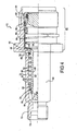
- FIG. 1 is a partial cross-sectional view of a valve assembly according to an embodiment of the present invention, showing a valve in an open position;
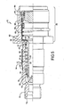
- FIG. 2 is a partial cross-sectional view of a valve assembly of FIG. 1, showing the valve in a closed position;
- FIG. 3A is a detailed view of the valve assembly shown in FIG. 1, illustrating a valve configuration according to an embodiment of the invention
- FIG. 3B is a detailed view of the valve assembly shown in FIG. 1, illustrating a valve configuration according to another embodiment of the invention
- FIG. 3C is a detailed view of the valve assembly shown in FIG. 1, illustrating a valve configuration according to another embodiment of the invention
- FIG. 4 is a partial cross-sectional view of a valve assembly according to another embodiment of the present invention, showing a valve in an open position;
- FIG. 5 is a partial cross-sectional view of the valve assembly of FIG. 4 shown with an optional sleeve;
- FIG. 6 is a partial cross-sectional view of a valve assembly according to another embodiment of the present invention, showing a valve in an open position;
- FIG. 7 is an end view of the valve assembly of FIG. 6.
- FIGS. 1 and 2 illustrate a partial cross-sectional view of a valve assembly 10 shown in accordance with an embodiment of the present invention.
- valve assembly 10 includes a body 12 having a bore 14 and a longitudinal axis A-A.
- a valve 16 is received within the bore 14 and is configured for axial movement between an open position (e.g., FIG. 1) in which fluid flow through the body 12 is permitted and a closed position (e.g., FIG. 2) in which fluid flow through the body 12 is prevented.
- valve 16 is generally cylindrical and includes a head portion 18 and an elongated stem portion 20 that includes a fluid flow passage 22 extending therethrough. At least one channel 24 extends through head portion 18 to provide fluid flow passage 22 in communication with the portion of bore 14 that is downstream of valve 16 when valve 16 is in the open position. Head portion 18 is adapted to engage an inner surface 26 of bore 14 downstream of channel 24 to prevent fluid flow through bore 14 when valve 16 is moved to the closed position. Bore 14 and valve 16 provide a low pressure drop fluid flow path through valve assembly 10 when the internal fluid pressure within valve assembly 10 is below a predetermined pressure discussed herein below.
- valve 16 is provided with a first outer surface 28 having a first diameter and a second outer surface 30 having a second diameter.
- a first sealing member 32 is secured for axial movement with valve 16 and is adapted to provide a seal between first outer surface 28 of valve 16 and body 12.
- a second sealing member 34 is secured for axial movement with valve 16 and is adapted to provide a seal between second outer surface 30 of valve 16 and body 12.
- first and second sealing members 32, 34 are spring energized seals that include a polymeric U-cup 36 and an energizing spring 38 received in a U-shaped opening of the U-cup 36 ( see, e.g., FIGS. 3A-3B).
- U-cup 36 is made from a fluoroplastic, such as PTFE, to prevent the U-cup material from bleeding into the body 12 material during prolonged periods of valve 16 being in the open position without movement.
- a closed end 40 of first sealing member 32 abuts a shoulder 42 on valve 16 and an open end 44 of first sealing member 32 is enagagable with a projection 46 on first outer surface 28 of valve 16 to secure first sealing member 32 on valve 16.
- a closed end 40 of second sealing member 34 abuts a first retainer 48 that is secured for axial movement with valve 16 and an open end 44 of second sealing member 34 is enagagable with a second retainer 50, such as a snap ring, which is secured to valve 16.
- retainer 48 may include a retaining ring 49 that engages second outer surface 30 of valve 16 to secure first retainer 48 to valve 16.
- first retainer 48 may be received in a recess in second outer surface 30 of valve 16 and secured therein by a retaining ring 49 that engages a groove in retainer 48, as shown in FIG. 3B, and biases first retainer 48 into the recess in second outer surface 30.
- body 12 also includes at least one bleed hole 52 that provides the exterior of body 12 in communication with bore 14.
- First and second sealing members 32, 34 are positioned axially fore and aft of bleed hole 52, respectively, such that each sealing member 32, 34 is subjected to a common reference fluid pressure (e.g., external fluid pressure) and an internal fluid pressure within the bore 14 of body 12.
- a common reference fluid pressure e.g., external fluid pressure
- the internal fluid pressure within bore 14 is applied to the open end 44 of first and second sealing members 32, 34 and the common reference pressure is applied to the closed end 40 of first and second sealing members 32, 34.
- a first portion of bore 14 adjacent first sealing member 32 is greater in diameter than a second portion of bore 14 adjacent second sealing member 34.
- a first surface area portion of bore 14 adjacent first sealing member 32 is greater than a second surface area portion of bore 14 adjacent second sealing member 34.
- the common reference pressure e.g., external fluid pressure
- the common reference pressure is lower than the internal fluid pressure within bore 14 such that the internal fluid pressure within bore 14 that is applied against the open end 44 of each sealing member 32, 34 forces the sealing members 32, 34 toward each other.
- valve 16 biases the valve toward the closed position. Accordingly, any internal fluid pressure greater than the reference pressure (e.g., external pressure) will function to force valve 16 toward the closed position.
- reference pressure e.g., external pressure
- second outer surface 30 of valve 16 is removed from inner surface 26 of bore 14 to form a pocket 54 within which is received a resiliently compressible member 56, such as a compression spring, positioned to bias valve 16 toward the open position.
- a resiliently compressible member 56 such as a compression spring
- a first end of resiliently compressible member 56 abuts shoulder 42 of valve 16 and a second end of resiliently compressible member 56 abuts an internal shoulder of body 12.
- the internal shoulder of body 12 is a spring seat 58 that is received in body 12 with valve 16 during assembly and is inhibited from axial movement in at least one direction by virtue of its engagement with body 12.
- valve seat 58 also functions as a retainer member for second sealing member 34, which eliminates the need for retainer 48.
- valve retaining member 60 is secured within body 12 and is engaged by valve 16 in the open position to prevent valve 16 from being pushed out of body 12 by resiliently compressible member 56.
- valve retaining member 60 is secured within body 12 by a retaining ring 62, such as a snap ring, which is secured in a groove in an inner surface of body 12.
- resiliently compressible member 56 is pre-loaded when valve 16 is secured within body 12 to bias valve 16 toward the open position shown in FIG. 1.
- the amount of pre-load is generally equal to the difference in surface area of the first and second sealing members multiplied by a predetermined pressure, minus a combined static break-away force required to unseat first and second sealing members 32, 34 from their stationary engagement with the inner wall of bore 14.
- valve 16 is normally in the open position and is moved to the closed position when the internal fluid pressure in bore 14 exceeds a predetermined pressure.
- the predetermined pressure is approximately equal to the pressure at which the force imparted on valve 16 by first sealing member 32 exceeds a sum of the forces imparted on the valve by second sealing member 34, and resiliently compressible member 56 and the combined static break-away force required to unseat first and second sealing members 32, 34 from their stationary engagement with the inner wall of bore 14.
- valve 10 Since the static break-away force is relatively high compared to the dynamic sliding force required to move first and second sealing members 32, 34 relative to the inner wall of bore 14, the valve 10 snaps closed once the force imparted on valve 16 by first sealing member 32 exceeds a sum of the forces imparted on the valve by second sealing member 34, and the resiliently compressible member 56, and the combined static break-away force require to unseat first and second sealing members 32, 34 from their stationary engagement with the inner wall of bore 14.
- valve 16 is adapted to return to the open position when the internal fluid pressure is substantially less than the predetermined pressure-a resetting feature that allows the valve 10 to continue to operate after the internal pressure exceeds the predetermined pressure and is then significantly reduced. This feature prevents valve 16 from cycling between the open and closed positions with small internal fluid pressure fluctuations around the predetermined fluid pressure.
- the internal fluid pressure at which the valve 16 returns to the open position is approximately one-fifth the predetermined pressure; however, the return pressure will depend on various factors, including the static break-away force required to unseat first and second sealing members 32, 34 from their stationary engagement with the inner wall of bore 14 and the spring-force exerted by resiliently compressible member 56.
- valve assembly 10 continuously “monitors” the pressure within bore 14 and the corresponding fluid line or system within which the valve assembly is installed, and functions in static or dynamic fluid flow conditions to isolate the fluid line or system components on the downstream side of valve 16 from potentially damaging increases in fluid pressure on the upstream side of valve 16. It will also be appreciated that valve assembly 10 does not need to be replaced once valve 16 is actuated, since valve 16 automatically reopens when the over-pressurized condition returns to a safe pressure condition.
- valve assembly 10 can be configured for use as a standard in-line device that detects an over-pressure condition at its inlet and closes virtually instantaneously to prevent the over-pressure condition and any impulse pressure spikes from exiting the valve assembly's outlet.
- body 12 may include a threaded male connector 70 on its downstream end 72 and a threaded female connector 74 on its upstream end 76 (see e.g., FIGS. 1 and 2), or any combination of industry standard connectors.
- valve assembly 10 of the present invention is not limited to a specific size and can cover a wide range of both conventional and unconventional sizes.
- valve assembly 10 may be configured as a coupling or an adapter configured to mate with a threaded or quick-connect/disconnect style fitting (not shown).
- valve assembly 10 may include a quick-connect coupling portion 80 having an axially moveable coupling valve 82 and a coupling valve retainer 84 that is threaded into body 12 to retain the coupling valve 82 within body 12; however, the coupling configuration shown in FIG. 4 is not intended to be limited thereto.
- a resiliently compressible member 86 such as a compression spring, is positioned between coupling valve 82 and retainer 60, and biases the coupling valve 82 toward the closed position shown in FIG. 4.
- a first sealing member 88 such as an O-ring or O-ring/packing ring combination, is positioned between body 12 and coupling valve retainer 84, and a second sealing member 90 is positioned between coupling valve retainer 84 and coupling valve 82 to inhibit fluid leakage between the components.
- An outer surface of body 12 may also include an optional sleeve 94 (FIG. 5) for preventing bleed hole 52 from becoming clogged with debris.
- Valve assembly 10 may also be adapted for bulk-head mounting and, when so configured, may include a bulk-head mounting flange 96, as shown in FIGS. 6 and 7.
- a cap 98 may be applied to the threaded upstream and downstream ends of body 12 or, when valve assembly 10 includes a quick-connect/disconnect coupling portion 80, a plug 100 may be secured to the quick-connect coupling portion 80 to inhibit dust, dirt and other debris from being received into the bore 14 of valve assembly 10.
Landscapes
- Engineering & Computer Science (AREA)
- General Engineering & Computer Science (AREA)
- Mechanical Engineering (AREA)
- Safety Valves (AREA)
- Lift Valve (AREA)
Abstract
Description
- The present invention relates generally to valve assemblies for hydraulic systems and, more particularly, to an over-pressure protection valve assembly for use in a hydraulic system.
- Devices for monitoring fluid flow and pressure in a hydraulic system and responding to pressure and flow transients that immediately follow a ruptured hydraulic line, hose or hydraulic device leak, so-called "hydraulic fuses," are known in the art. Hydraulic fuses are typically in-line valves that protect a hydraulic system or subsystem by sensing increased flow through the valve, resulting from a rupture line or leak, and closing the valve to block fluid flow upstream of the rupture to prevent further spillage.
- While hydraulic fuses adequately protect a hydraulic system from fluid loss, they are generally incapable of protecting a hydraulic system from over-pressurization. To prevent over-pressurization, hydraulic systems or subsystems typically include a burst disk, pressure relief valve or other pressure relief device. While these devices effectively vent pressurized fluid when a hydraulic system or subsystem is over-pressurized, they exhibit a number of limitations. Among other limitations, burst disks must be replaced once they are ruptured. Additionally, unlike in-line hydraulic fuses, burst disks require additional plumbing for discharging pressurized fluid. Another limitation of burst disks is that they expose a downstream portion of the hydraulic system to a momentary high-pressure impulse prior to and during rupture. Moreover, burst disks have a tendency to fail due to low-pressure cycling fatigue.
- Like burst disks, pressure relief valves also require additional plumbing for fluid discharge and expose a downstream portion of the hydraulic system to a momentary high-pressure impulse prior to the valve opening. Another limitation of pressure relief valves is that they are relatively large in size and weight, rendering them unsatisfactory for use in hydraulic systems where size and weight must be minimized.
- For at least these reasons, a need exists for a relatively small and lightweight, in-line hydraulic device that monitors static and dynamic fluid pressure in a hydraulic system or subsystem and closes virtually instantaneously upon detection of an over-pressure condition to prevent a portion of the hydraulic system downstream of the valve from being exposed to the over-pressure condition and any associated pressure impulse. Moreover, a need exists for an in-line hydraulic device that automatically reopens when the over-pressurized condition returns to a safe pressure condition.
- A valve assembly is provided that includes a body having a bore and a longitudinal axis. A valve is received within the bore and is configured for axial movement between an open position in which fluid flow through the body is permitted and a closed position in which fluid flow through the body is prevented. First and second sealing members are secured for movement with the valve and are positioned between the valve and the body such that an internal fluid pressure within the bore is applied to a first side of the first and second sealing members and a common reference pressure is applied to a second side of the first and second sealing members. A first surface area portion of the bore adjacent the first sealing member is greater than a second surface area portion of the bore adjacent second sealing member such that an axial force imparted on the valve adjacent the second sealing member is less than an axial force imparted on the valve adjacent the first sealing member. A resiliently compressible member is positioned to bias the valve toward the open position. The valve is normally in the open position and is moved to the closed position when the internal fluid pressure exceeds a predetermined pressure. The valve is adapted to return to the open position when the internal fluid pressure is substantially less than the predetermined pressure.
- Other aspects of the invention will be apparent to those skilled in the art after review of the drawing and detail description provided below.
- The present invention will now be described, by way of example, with reference to the accompanying drawings, in which:
- FIG. 1 is a partial cross-sectional view of a valve assembly according to an embodiment of the present invention, showing a valve in an open position;
- FIG. 2 is a partial cross-sectional view of a valve assembly of FIG. 1, showing the valve in a closed position;
- FIG. 3A is a detailed view of the valve assembly shown in FIG. 1, illustrating a valve configuration according to an embodiment of the invention;
- FIG. 3B is a detailed view of the valve assembly shown in FIG. 1, illustrating a valve configuration according to another embodiment of the invention;
- FIG. 3C is a detailed view of the valve assembly shown in FIG. 1, illustrating a valve configuration according to another embodiment of the invention;
- FIG. 4 is a partial cross-sectional view of a valve assembly according to another embodiment of the present invention, showing a valve in an open position;
- FIG. 5 is a partial cross-sectional view of the valve assembly of FIG. 4 shown with an optional sleeve;
- FIG. 6 is a partial cross-sectional view of a valve assembly according to another embodiment of the present invention, showing a valve in an open position; and
- FIG. 7 is an end view of the valve assembly of FIG. 6.
- FIGS. 1 and 2 illustrate a partial cross-sectional view of a
valve assembly 10 shown in accordance with an embodiment of the present invention. In the illustrated embodiment,valve assembly 10 includes abody 12 having abore 14 and a longitudinal axis A-A. Avalve 16 is received within thebore 14 and is configured for axial movement between an open position (e.g., FIG. 1) in which fluid flow through thebody 12 is permitted and a closed position (e.g., FIG. 2) in which fluid flow through thebody 12 is prevented. - In an embodiment,
valve 16 is generally cylindrical and includes ahead portion 18 and anelongated stem portion 20 that includes afluid flow passage 22 extending therethrough. At least onechannel 24 extends throughhead portion 18 to providefluid flow passage 22 in communication with the portion ofbore 14 that is downstream ofvalve 16 whenvalve 16 is in the open position.Head portion 18 is adapted to engage aninner surface 26 ofbore 14 downstream ofchannel 24 to prevent fluid flow throughbore 14 whenvalve 16 is moved to the closed position.Bore 14 andvalve 16 provide a low pressure drop fluid flow path throughvalve assembly 10 when the internal fluid pressure withinvalve assembly 10 is below a predetermined pressure discussed herein below. - Referring still to FIGS. 1 and 2,
valve 16 is provided with a firstouter surface 28 having a first diameter and a secondouter surface 30 having a second diameter. Afirst sealing member 32 is secured for axial movement withvalve 16 and is adapted to provide a seal between firstouter surface 28 ofvalve 16 andbody 12. Similarly, asecond sealing member 34 is secured for axial movement withvalve 16 and is adapted to provide a seal between secondouter surface 30 ofvalve 16 andbody 12. - In an embodiment, first and
second sealing members polymeric U-cup 36 and an energizingspring 38 received in a U-shaped opening of the U-cup 36 (see, e.g., FIGS. 3A-3B). In a particular configuration, U-cup 36 is made from a fluoroplastic, such as PTFE, to prevent the U-cup material from bleeding into thebody 12 material during prolonged periods ofvalve 16 being in the open position without movement. - As shown in FIGS. 1 and 2, a closed
end 40 offirst sealing member 32 abuts ashoulder 42 onvalve 16 and anopen end 44 offirst sealing member 32 is enagagable with aprojection 46 on firstouter surface 28 ofvalve 16 to securefirst sealing member 32 onvalve 16. As shown in FIG. 3, a closedend 40 ofsecond sealing member 34 abuts afirst retainer 48 that is secured for axial movement withvalve 16 and anopen end 44 ofsecond sealing member 34 is enagagable with asecond retainer 50, such as a snap ring, which is secured tovalve 16. - As shown in FIG. 3A,
retainer 48 may include aretaining ring 49 that engages secondouter surface 30 ofvalve 16 to securefirst retainer 48 tovalve 16. Alternatively,first retainer 48 may be received in a recess in secondouter surface 30 ofvalve 16 and secured therein by aretaining ring 49 that engages a groove inretainer 48, as shown in FIG. 3B, and biases first retainer 48 into the recess in secondouter surface 30. - Referring again to the embodiment of the invention shown in FIGS. 1 and 2,
body 12 also includes at least onebleed hole 52 that provides the exterior ofbody 12 in communication withbore 14. First andsecond sealing members bleed hole 52, respectively, such that each sealingmember bore 14 ofbody 12. In the illustrated embodiment, the internal fluid pressure withinbore 14 is applied to theopen end 44 of first andsecond sealing members end 40 of first andsecond sealing members - Referring still to FIG. 1, a first portion of
bore 14 adjacentfirst sealing member 32 is greater in diameter than a second portion ofbore 14 adjacentsecond sealing member 34. When so configured, a first surface area portion ofbore 14 adjacentfirst sealing member 32 is greater than a second surface area portion ofbore 14 adjacentsecond sealing member 34. In an embodiment, the common reference pressure (e.g., external fluid pressure) is lower than the internal fluid pressure withinbore 14 such that the internal fluid pressure withinbore 14 that is applied against theopen end 44 of eachsealing member members bore 14 adjacent first andsecond sealing members valve 16 adjacent second sealingmember 34 is less than the axial force imparted onvalve 16 adjacent first sealingmember 32, as demonstrated below:

wherein: - A1 = relevant surface area of a first portion of the bore adjacent the first sealing member;
- A2 = relevant surface area of a second portion of the bore adjacent the second sealing member;
- F1 = force exerted on the valve adjacent the first sealing member;
- F2 = force exerted on the valve adjacent the second sealing member; and
- PInternal = internal fluid pressure within the bore.
- The imbalance of force imparted on
valve 16 biases the valve toward the closed position. Accordingly, any internal fluid pressure greater than the reference pressure (e.g., external pressure) will function to forcevalve 16 toward the closed position. - As illustrated in FIGS. 1 and 2, second
outer surface 30 ofvalve 16 is removed frominner surface 26 ofbore 14 to form apocket 54 within which is received a resilientlycompressible member 56, such as a compression spring, positioned to biasvalve 16 toward the open position. In an embodiment, a first end of resilientlycompressible member 56 abutsshoulder 42 ofvalve 16 and a second end of resilientlycompressible member 56 abuts an internal shoulder ofbody 12. In the configuration shown in FIGS. 1 and 2, the internal shoulder ofbody 12 is aspring seat 58 that is received inbody 12 withvalve 16 during assembly and is inhibited from axial movement in at least one direction by virtue of its engagement withbody 12. In the embodiment shown in FIG. 3C,valve seat 58 also functions as a retainer member for second sealingmember 34, which eliminates the need forretainer 48. - Once
valve 16 is received intobody 12 during assembly, avalve retaining member 60 is secured withinbody 12 and is engaged byvalve 16 in the open position to preventvalve 16 from being pushed out ofbody 12 by resilientlycompressible member 56. In the embodiment illustrated in FIGS. 1 and 2,valve retaining member 60 is secured withinbody 12 by a retainingring 62, such as a snap ring, which is secured in a groove in an inner surface ofbody 12. - In an embodiment, resiliently
compressible member 56 is pre-loaded whenvalve 16 is secured withinbody 12 to biasvalve 16 toward the open position shown in FIG. 1. The amount of pre-load is generally equal to the difference in surface area of the first and second sealing members multiplied by a predetermined pressure, minus a combined static break-away force required to unseat first andsecond sealing members bore 14. - During operation of
valve assembly 10,valve 16 is normally in the open position and is moved to the closed position when the internal fluid pressure inbore 14 exceeds a predetermined pressure. In an embodiment, the predetermined pressure is approximately equal to the pressure at which the force imparted onvalve 16 by first sealingmember 32 exceeds a sum of the forces imparted on the valve by second sealingmember 34, and resilientlycompressible member 56 and the combined static break-away force required to unseat first andsecond sealing members bore 14. Since the static break-away force is relatively high compared to the dynamic sliding force required to move first andsecond sealing members bore 14, thevalve 10 snaps closed once the force imparted onvalve 16 by first sealingmember 32 exceeds a sum of the forces imparted on the valve by second sealingmember 34, and the resilientlycompressible member 56, and the combined static break-away force require to unseat first andsecond sealing members bore 14. - Unlike some prior art valve assemblies that gradually close as the internal fluid pressure approaches the actuation pressure, there are no intermediate valve travel positions between the open and closed positions-the
valve 16 is either in the open position or the closed position. In contrast to other prior art valve assemblies,valve 16 is adapted to return to the open position when the internal fluid pressure is substantially less than the predetermined pressure-a resetting feature that allows thevalve 10 to continue to operate after the internal pressure exceeds the predetermined pressure and is then significantly reduced. This feature preventsvalve 16 from cycling between the open and closed positions with small internal fluid pressure fluctuations around the predetermined fluid pressure. In an embodiment, the internal fluid pressure at which thevalve 16 returns to the open position is approximately one-fifth the predetermined pressure; however, the return pressure will depend on various factors, including the static break-away force required to unseat first andsecond sealing members bore 14 and the spring-force exerted by resilientlycompressible member 56. - In view of the foregoing description, it will be appreciated that
valve assembly 10 continuously "monitors" the pressure withinbore 14 and the corresponding fluid line or system within which the valve assembly is installed, and functions in static or dynamic fluid flow conditions to isolate the fluid line or system components on the downstream side ofvalve 16 from potentially damaging increases in fluid pressure on the upstream side ofvalve 16. It will also be appreciated thatvalve assembly 10 does not need to be replaced oncevalve 16 is actuated, sincevalve 16 automatically reopens when the over-pressurized condition returns to a safe pressure condition. - If desired,
valve assembly 10 can be configured for use as a standard in-line device that detects an over-pressure condition at its inlet and closes virtually instantaneously to prevent the over-pressure condition and any impulse pressure spikes from exiting the valve assembly's outlet. When so configured,body 12 may include a threadedmale connector 70 on itsdownstream end 72 and a threadedfemale connector 74 on its upstream end 76 (see e.g., FIGS. 1 and 2), or any combination of industry standard connectors. Furthermore,valve assembly 10 of the present invention is not limited to a specific size and can cover a wide range of both conventional and unconventional sizes. - Alternatively,
valve assembly 10 may be configured as a coupling or an adapter configured to mate with a threaded or quick-connect/disconnect style fitting (not shown). For example, as shown in FIG. 4,valve assembly 10 may include a quick-connect coupling portion 80 having an axiallymoveable coupling valve 82 and acoupling valve retainer 84 that is threaded intobody 12 to retain thecoupling valve 82 withinbody 12; however, the coupling configuration shown in FIG. 4 is not intended to be limited thereto. A resilientlycompressible member 86, such as a compression spring, is positioned betweencoupling valve 82 andretainer 60, and biases thecoupling valve 82 toward the closed position shown in FIG. 4. A first sealingmember 88, such as an O-ring or O-ring/packing ring combination, is positioned betweenbody 12 andcoupling valve retainer 84, and asecond sealing member 90 is positioned betweencoupling valve retainer 84 andcoupling valve 82 to inhibit fluid leakage between the components. An outer surface ofbody 12 may also include an optional sleeve 94 (FIG. 5) for preventingbleed hole 52 from becoming clogged with debris. -
Valve assembly 10 may also be adapted for bulk-head mounting and, when so configured, may include a bulk-head mounting flange 96, as shown in FIGS. 6 and 7. To protectvalve assembly 10 during shipping, acap 98 may be applied to the threaded upstream and downstream ends ofbody 12 or, whenvalve assembly 10 includes a quick-connect/disconnect coupling portion 80, aplug 100 may be secured to the quick-connect coupling portion 80 to inhibit dust, dirt and other debris from being received into thebore 14 ofvalve assembly 10. - The present invention has been particularly shown and described with reference to the foregoing embodiments, which are merely illustrative of the best modes for carrying out the invention. It should be understood by those skilled in the art that various alternatives to the embodiments of the invention described herein may be employed in practicing the invention without departing from the spirit and scope of the invention as defmed in the following claims. It is intended that the following claims define the scope of the invention and that the method and apparatus within the scope of these claims and their equivalents be covered thereby. This description of the invention should be understood to include all novel and non-obvious combinations of elements described herein, and claims may be presented in this or a later application to any novel and non-obvious combination of these elements. Moreover, the foregoing embodiments are illustrative, and no single feature or element is essential to all possible combinations that may be claimed in this or a later application.
Claims (21)
- A valve assembly (10), comprising:a body (12) including a bore (14) and a longitudinal axis (A-A);a valve (16) received within the bore (14) and configured for axial movement between an open position in which fluid flow through the body (12) is permitted and a closed position in which fluid flow through the body (12) is prevented;first and second sealing members (32,34) secured for movement with the valve (16) and positioned between the valve (16) and the body (12) such that an internal fluid pressure within the bore (14) is applied to a first side of the first and second sealing members (32,34) and a common reference pressure is applied to a second side of the first and second sealing members (32, 34), a first surface area portion of the bore (14) adjacent the first sealing member (32) is greater than a second surface area portion of the bore (14) adjacent second sealing member (34) such that an axial force imparted on the valve (16) adjacent the second sealing member (34) is less than an axial force imparted on the valve (16) adjacent the first sealing member (32);a resiliently compressible member (56) positioned to bias the valve (16) toward the open position; andwherein the valve (16) is normally in the open position and is moved to the closed position when the internal fluid pressure exceeds a predetermined pressure, and wherein the valve (16) is adapted to return to the open position when the internal fluid pressure is substantially less than the predetermined pressure.
- The valve assembly of claim 1, wherein the first and second sealing members (32, 34) each include an open end (44) and a closed end (40), and wherein the internal fluid pressure is applied to the open end (44) and the common reference pressure is applied to the closed end (40).
- The valve assembly of claim 1, wherein the first and second sealing members (32, 34) are spring energized seals that include a polymeric U-cup (36) and a spring (38) received in a U-shaped opening of the U-cup (36).
- The valve assembly of claim 1, wherein the resiliently compressible member (56) is a compression spring.
- The valve assembly of claim 1, wherein a first end of the resiliently compressible member (56) abuts an exterior shoulder (42) of the valve (16) and a second end of the resiliently compressible member (56) abuts an internal shoulder of the body (12).
- The valve assembly of claim 5, wherein the internal shoulder of the body (12) is a spring seat (58) that is received in the body (12) with the valve (16) and is inhibited from axial movement in at least one direction by virtue of its engagement with the body (12).
- The valve assembly of claim 1, wherein the resiliently compressible member (56) is pre-loaded when the valve (16) is received in the body (12).
- The valve assembly of claim 7, wherein the amount of pre-load is generally equal to the difference in surface area of the first and second sealing members (32, 34) multiplied by the predetermined pressure, minus a combined static break-away force of the first and second sealing members (32, 34).
- The valve assembly of claim 1, wherein the predetermined pressure is approximately equal to the pressure at which the force imparted on the valve (16) adjacent the first sealing member (32) exceeds a sum of the forces imparted on the valve (16) adjacent the second sealing member (34) and the resiliently compressible member (56), and a combined static break-away force require to unseat first and second sealing members (32, 34) from their stationary engagement with an inner wall of the bore (14).
- The valve assembly of claim 1, wherein the internal fluid pressure at which the valve (16) returns to the open position is approximately one-fifth the predetermined pressure.
- The valve assembly of claim 1, wherein the valve assembly (10) also includes a quick connect coupling portion (80) having an axially moveable coupling valve (82) and a coupling valve retainer (84) that is threaded into the body (12) to retain the coupling valve (82) within the body (12).
- A valve assembly (10), comprising:a body (12) including a longitudinal axis (A-A), a bore (14) and at least one bleed hole (52) that provides an exterior of the body (12) in communication with the bore (14);a valve (16) received within the bore (14) and configured for axial movement between an open position in which fluid flow through the body (12) is permitted and a closed position in which fluid flow through the body (12) is prevented;first and second sealing members (32, 34) secured for axial movement with the valve (16) and adapted to provide a seal between the valve (16) and the body (12), the sealing members (32, 34) positioned axially fore and aft of the bleed hole (52) such that each sealing member (32, 34) is subjected to an external fluid pressure and an internal fluid pressure within the bore (14) of the valve body (12);a resiliently compressible member (56) positioned to bias the valve toward the open position; andwherein the valve (16) is normally in the open position and is moved to the closed position when the internal fluid pressure exceeds a predetermined pressure, and wherein the valve (16) is adapted to return to the open position when the internal fluid pressure is substantially less than the predetermined pressure.
- The valve assembly of claim 12, wherein a first surface area portion of the bore (14) adjacent the first sealing member (32) is greater than a second surface area portion of the bore (14) adjacent second sealing member (34) such that an axial force imparted on the valve (16) adjacent the second sealing member (34) is less than an axial force imparted on the valve (16) adjacent the first sealing member (32).
- The valve assembly of claim 12, wherein the first and second sealing members (32, 34) each include an open end (44) and a closed end (40), and wherein the external fluid pressure is applied to the closed end (40) and the internal fluid pressure is applied to the open end (44).
- The valve assembly of claim 12, wherein the first and second sealing members (32, 34) are spring energized seals that include a polymeric U-cup (36) and a spring (38) received in a U-shaped opening of the U-cup (36).
- The valve assembly of claim 12, wherein a first end of the resiliently compressible member (56) abuts an exterior shoulder (42) of the valve (16) and a second end of the resiliently compressible member (56) abuts an internal shoulder of the body (12).
- The valve assembly of claim 16, wherein the internal shoulder of the body (12) is a spring seat (58) that is received in the body (12) with the valve (16) and is inhibited from axial movement in at least one direction by virtue of its engagement with the body (12).
- The valve assembly of claim 12, wherein the resiliently compressible member (56) is pre-loaded when the valve (16) is received in the body (12), the amount of pre-load generally equal to the difference in surface area of the sealing members (32, 34) multiplied by the predetermined pressure, minus a combined static break-away force of the first and second sealing members (32, 34).
- The valve assembly of claim 12, wherein the predetermined pressure is approximately equal to the pressure at which the force imparted on the valve (16) adjacent the first sealing member (32) exceeds a sum of the forces imparted on the valve (16) adjacent the second sealing member (34) and the resiliently compressible member (56) and a combined static break-away force require to unseat first and second sealing members (32, 34) from their stationary engagement with an inner wall of the bore (14).
- The valve assembly of claim 12, wherein the internal fluid pressure at which the valve (16) returns to the open position is approximately one-fifth the predetermined pressure.
- The valve assembly of claim 12, wherein the valve assembly (10) also includes a quick connect coupling portion (80) having an axially moveable coupling valve (82) and a coupling valve retainer (84) that is threaded into the body (12) to retain the coupling valve (82) within the body (12).
Applications Claiming Priority (1)
| Application Number | Priority Date | Filing Date | Title |
|---|---|---|---|
| US11/012,624 US7213611B2 (en) | 2004-12-15 | 2004-12-15 | Valve assembly |
Publications (2)
| Publication Number | Publication Date |
|---|---|
| EP1672259A1 true EP1672259A1 (en) | 2006-06-21 |
| EP1672259B1 EP1672259B1 (en) | 2011-09-14 |
Family
ID=35995301
Family Applications (1)
| Application Number | Title | Priority Date | Filing Date |
|---|---|---|---|
| EP20050027178 Expired - Lifetime EP1672259B1 (en) | 2004-12-15 | 2005-12-13 | Safety valve assembly |
Country Status (2)
| Country | Link |
|---|---|
| US (1) | US7213611B2 (en) |
| EP (1) | EP1672259B1 (en) |
Cited By (2)
| Publication number | Priority date | Publication date | Assignee | Title |
|---|---|---|---|---|
| EP2551568A1 (en) | 2011-07-26 | 2013-01-30 | Horst Thiele Maschinenbau-Hydraulische Geräte GmbH | Pipe break valve device |
| FR3064962A1 (en) * | 2017-04-10 | 2018-10-12 | Valeo Systemes D'essuyage | PRESSURE LIMITING DEVICE EQUIPPED WITH A WINDSCREEN LIQUID DISPENSING DEVICE FOR A MOTOR VEHICLE |
Families Citing this family (13)
| Publication number | Priority date | Publication date | Assignee | Title |
|---|---|---|---|---|
| ITMI20051643A1 (en) * | 2005-09-07 | 2007-03-08 | Faster Spa | QUICK COUPLING WITH COMPENSATION OF THE COUPLING TOLERANCES |
| US7387012B2 (en) * | 2006-07-14 | 2008-06-17 | Veyance Technologies, Inc. | Leak detection sensor system and method for double carcass hose |
| US7509841B2 (en) * | 2006-07-14 | 2009-03-31 | Veyance Technologies, Inc. | Flexible leak detection system and method for double carcass hose |
| TW201030485A (en) * | 2009-02-12 | 2010-08-16 | Nan Ya Printed Circuit Board | Pressure control system and pressure regulating valve thereof |
| US8985553B2 (en) | 2009-08-10 | 2015-03-24 | Parker Hannifin Corporation | Pressure protection valve |
| WO2011136999A1 (en) * | 2010-04-28 | 2011-11-03 | 3M Innovative Properties Company | Pressure-control valve |
| US20120241018A1 (en) * | 2011-03-23 | 2012-09-27 | Bryan Alfano | Over-pressure protection device |
| US20160102799A1 (en) | 2014-10-14 | 2016-04-14 | Dennis A. Vogl | Anti-debris device for covering connectors in fluid system |
| GB2552168B (en) * | 2016-07-11 | 2021-12-22 | Truma Geraetetechnik Gmbh & Co Kg | Pressure regulator |
| US20180363790A1 (en) * | 2017-06-15 | 2018-12-20 | Banza Stamping Industry Corp. | Universal air pressure valve module |
| US12287038B2 (en) * | 2020-12-11 | 2025-04-29 | Jtekt Corporation | Pressure reduction valve |
| WO2023028759A1 (en) * | 2021-08-30 | 2023-03-09 | Engineered Controls International, Llc | Excess flow valve for cryogenic fluid tank |
| US20240353871A1 (en) * | 2023-04-24 | 2024-10-24 | Kalsi Engineering, Inc. | Passive modulating design for fast responding control valves for high pressure gas applications |
Citations (3)
| Publication number | Priority date | Publication date | Assignee | Title |
|---|---|---|---|---|
| BE632658A (en) * | ||||
| US4013299A (en) * | 1975-11-14 | 1977-03-22 | Parker-Hannifin Corporation | Sealing ring |
| WO1998008012A1 (en) * | 1996-08-19 | 1998-02-26 | Australian Water Products Pty. Ltd. | Outlet pressure limiting valve |
Family Cites Families (12)
| Publication number | Priority date | Publication date | Assignee | Title |
|---|---|---|---|---|
| US2366832A (en) * | 1942-01-17 | 1945-01-09 | Johns Manville | Packing |
| US2446355A (en) * | 1944-07-20 | 1948-08-03 | Jeffrey Mfg Co | Detent mechanism for pressure regulators |
| GB1017403A (en) * | 1961-09-18 | 1966-01-19 | Philmac Ltd | Improvements in or relating to fluid flow-control valves |
| US3511266A (en) * | 1967-03-13 | 1970-05-12 | Firewel Co Inc | Shut off and pressure regulating valve |
| US3995656A (en) * | 1972-02-15 | 1976-12-07 | Lif-O-Gen, Inc. | High pressure gas regulator |
| US4924904A (en) * | 1986-06-30 | 1990-05-15 | Puritan-Bennett Corporation | Adjustable pressure regulator device |
| DE3636409C2 (en) * | 1986-10-25 | 1995-06-08 | Teves Gmbh Alfred | Pressure control valve |
| DK0536434T3 (en) * | 1991-10-08 | 1994-10-24 | Klein Rectus App | Self-venting quick coupling for compressed gas, especially compressed air lines |
| US5143347A (en) * | 1992-01-14 | 1992-09-01 | Lee Yeong D | Revolvable quick coupling |
| US5255711A (en) * | 1992-08-28 | 1993-10-26 | Hughes Aircraft Company | Spring-loaded pressure regulating valve including rolling diaphragm and compensation for variation of spring force with diaphragm displacement |
| GB9719604D0 (en) * | 1997-09-15 | 1997-11-19 | Protector Technologies Bv | Gas regulator/valve device |
| US6672332B2 (en) * | 2001-10-23 | 2004-01-06 | Hose Shop, Ltd. | Adjustable vertical pressure regulator |
-
2004
- 2004-12-15 US US11/012,624 patent/US7213611B2/en not_active Expired - Fee Related
-
2005
- 2005-12-13 EP EP20050027178 patent/EP1672259B1/en not_active Expired - Lifetime
Patent Citations (3)
| Publication number | Priority date | Publication date | Assignee | Title |
|---|---|---|---|---|
| BE632658A (en) * | ||||
| US4013299A (en) * | 1975-11-14 | 1977-03-22 | Parker-Hannifin Corporation | Sealing ring |
| WO1998008012A1 (en) * | 1996-08-19 | 1998-02-26 | Australian Water Products Pty. Ltd. | Outlet pressure limiting valve |
Cited By (4)
| Publication number | Priority date | Publication date | Assignee | Title |
|---|---|---|---|---|
| EP2551568A1 (en) | 2011-07-26 | 2013-01-30 | Horst Thiele Maschinenbau-Hydraulische Geräte GmbH | Pipe break valve device |
| US9234600B2 (en) | 2011-07-26 | 2016-01-12 | Horst Thiele Maschinenbau-Hydraulische Gerate GmbH | Pipe break valve device |
| FR3064962A1 (en) * | 2017-04-10 | 2018-10-12 | Valeo Systemes D'essuyage | PRESSURE LIMITING DEVICE EQUIPPED WITH A WINDSCREEN LIQUID DISPENSING DEVICE FOR A MOTOR VEHICLE |
| WO2018188951A1 (en) * | 2017-04-10 | 2018-10-18 | Valeo Systèmes d'Essuyage | Pressure limiting device fitted to a device for dispensing windscreen-washing fluid for a motor vehicle |
Also Published As
| Publication number | Publication date |
|---|---|
| US20060124174A1 (en) | 2006-06-15 |
| EP1672259B1 (en) | 2011-09-14 |
| US7213611B2 (en) | 2007-05-08 |
Similar Documents
| Publication | Publication Date | Title |
|---|---|---|
| US7213611B2 (en) | Valve assembly | |
| US6634375B2 (en) | Leak arresting valve | |
| US4090524A (en) | Frangible valved fitting | |
| US6206032B1 (en) | High pressure check valve fittings | |
| US8069950B1 (en) | Environmental compressor protection assembly | |
| CA3019485C (en) | Pressure relief valve with stop | |
| US9970568B2 (en) | Emergency shut-off valve | |
| US10221953B2 (en) | Non chattering pressure relief valve | |
| US4172468A (en) | Pressure shock absorber for oxygen-regulator supply system | |
| EP2183510B1 (en) | Combination relief valve and injection fitting | |
| US11506304B2 (en) | Indicators for valves | |
| US5979488A (en) | Bleed system | |
| GB1573903A (en) | Resettable pressure responsive valve | |
| US20110186763A1 (en) | Pressure by-pass valve | |
| US20180142793A1 (en) | Coupling and method thereof | |
| US4120315A (en) | Velocity check valve | |
| US11703892B2 (en) | Pressure regulator | |
| EP3794292B1 (en) | Fluid material injection device | |
| US3443572A (en) | Pressure relief device | |
| US8397748B2 (en) | Check valve having two seats | |
| EP2626611B1 (en) | Coupling system for connecting a pressure tube to a valve body | |
| GB2055177A (en) | In line back flow preventer |
Legal Events
| Date | Code | Title | Description |
|---|---|---|---|
| PUAI | Public reference made under article 153(3) epc to a published international application that has entered the european phase |
Free format text: ORIGINAL CODE: 0009012 |
|
| AK | Designated contracting states |
Kind code of ref document: A1 Designated state(s): AT BE BG CH CY CZ DE DK EE ES FI FR GB GR HU IE IS IT LI LT LU LV MC NL PL PT RO SE SI SK TR |
|
| AX | Request for extension of the european patent |
Extension state: AL BA HR MK YU |
|
| 17P | Request for examination filed |
Effective date: 20060826 |
|
| 17Q | First examination report despatched |
Effective date: 20061005 |
|
| AKX | Designation fees paid |
Designated state(s): FR GB |
|
| REG | Reference to a national code |
Ref country code: DE Ref legal event code: 8566 |
|
| GRAP | Despatch of communication of intention to grant a patent |
Free format text: ORIGINAL CODE: EPIDOSNIGR1 |
|
| GRAS | Grant fee paid |
Free format text: ORIGINAL CODE: EPIDOSNIGR3 |
|
| GRAA | (expected) grant |
Free format text: ORIGINAL CODE: 0009210 |
|
| AK | Designated contracting states |
Kind code of ref document: B1 Designated state(s): FR GB |
|
| PLBE | No opposition filed within time limit |
Free format text: ORIGINAL CODE: 0009261 |
|
| STAA | Information on the status of an ep patent application or granted ep patent |
Free format text: STATUS: NO OPPOSITION FILED WITHIN TIME LIMIT |
|
| 26N | No opposition filed |
Effective date: 20120615 |
|
| PGFP | Annual fee paid to national office [announced via postgrant information from national office to epo] |
Ref country code: GB Payment date: 20141124 Year of fee payment: 10 |
|
| PGFP | Annual fee paid to national office [announced via postgrant information from national office to epo] |
Ref country code: FR Payment date: 20141124 Year of fee payment: 10 |
|
| GBPC | Gb: european patent ceased through non-payment of renewal fee |
Effective date: 20151213 |
|
| REG | Reference to a national code |
Ref country code: FR Ref legal event code: ST Effective date: 20160831 |
|
| PG25 | Lapsed in a contracting state [announced via postgrant information from national office to epo] |
Ref country code: GB Free format text: LAPSE BECAUSE OF NON-PAYMENT OF DUE FEES Effective date: 20151213 |
|
| PG25 | Lapsed in a contracting state [announced via postgrant information from national office to epo] |
Ref country code: FR Free format text: LAPSE BECAUSE OF NON-PAYMENT OF DUE FEES Effective date: 20151231 |