EP1672241A1 - Spacer for coil spring - Google Patents
Spacer for coil spring Download PDFInfo
- Publication number
- EP1672241A1 EP1672241A1 EP05027655A EP05027655A EP1672241A1 EP 1672241 A1 EP1672241 A1 EP 1672241A1 EP 05027655 A EP05027655 A EP 05027655A EP 05027655 A EP05027655 A EP 05027655A EP 1672241 A1 EP1672241 A1 EP 1672241A1
- Authority
- EP
- European Patent Office
- Prior art keywords
- spring
- turn
- contact preventive
- preventive portion
- spacer
- Prior art date
- Legal status (The legal status is an assumption and is not a legal conclusion. Google has not performed a legal analysis and makes no representation as to the accuracy of the status listed.)
- Granted
Links
- 125000006850 spacer group Chemical group 0.000 title claims abstract description 169
- 230000003449 preventive effect Effects 0.000 claims abstract description 145
- 239000000725 suspension Substances 0.000 claims abstract description 60
- 230000002093 peripheral effect Effects 0.000 claims description 28
- 239000000853 adhesive Substances 0.000 claims description 4
- 230000001070 adhesive effect Effects 0.000 claims description 4
- 238000000034 method Methods 0.000 description 15
- 238000005299 abrasion Methods 0.000 description 10
- 238000010276 construction Methods 0.000 description 9
- 229920003002 synthetic resin Polymers 0.000 description 9
- 239000000057 synthetic resin Substances 0.000 description 9
- 239000006185 dispersion Substances 0.000 description 6
- 239000002184 metal Substances 0.000 description 4
- 229920001875 Ebonite Polymers 0.000 description 3
- 230000033001 locomotion Effects 0.000 description 3
- 239000000463 material Substances 0.000 description 3
- 230000004308 accommodation Effects 0.000 description 2
- 230000008602 contraction Effects 0.000 description 2
- 238000002485 combustion reaction Methods 0.000 description 1
- 238000001914 filtration Methods 0.000 description 1
- 238000000465 moulding Methods 0.000 description 1
- 230000001105 regulatory effect Effects 0.000 description 1
Images













Classifications
-
- F—MECHANICAL ENGINEERING; LIGHTING; HEATING; WEAPONS; BLASTING
- F16—ENGINEERING ELEMENTS AND UNITS; GENERAL MEASURES FOR PRODUCING AND MAINTAINING EFFECTIVE FUNCTIONING OF MACHINES OR INSTALLATIONS; THERMAL INSULATION IN GENERAL
- F16F—SPRINGS; SHOCK-ABSORBERS; MEANS FOR DAMPING VIBRATION
- F16F1/00—Springs
- F16F1/02—Springs made of steel or other material having low internal friction; Wound, torsion, leaf, cup, ring or the like springs, the material of the spring not being relevant
- F16F1/04—Wound springs
- F16F1/12—Attachments or mountings
- F16F1/126—Attachments or mountings comprising an element between the end coil of the spring and the support proper, e.g. an elastomeric annulus
-
- F—MECHANICAL ENGINEERING; LIGHTING; HEATING; WEAPONS; BLASTING
- F16—ENGINEERING ELEMENTS AND UNITS; GENERAL MEASURES FOR PRODUCING AND MAINTAINING EFFECTIVE FUNCTIONING OF MACHINES OR INSTALLATIONS; THERMAL INSULATION IN GENERAL
- F16F—SPRINGS; SHOCK-ABSORBERS; MEANS FOR DAMPING VIBRATION
- F16F1/00—Springs
- F16F1/02—Springs made of steel or other material having low internal friction; Wound, torsion, leaf, cup, ring or the like springs, the material of the spring not being relevant
- F16F1/04—Wound springs
- F16F1/12—Attachments or mountings
- F16F1/13—Attachments or mountings comprising inserts and spacers between the windings for changing the mechanical or physical characteristics of the spring
Definitions
- the present invention relates to a suspension unit comprising a spring spacer capable of preventing abrasion of a spring, which is made of Ti or the like and low in surface hardness, and a vehicle.
- motorcycles used for specific applications such as race or the like adopt springs, which are made of Ti to be lightweight as compared with conventional springs made of Fe, for suspension units or the like.
- springs which are made of Ti to be lightweight as compared with conventional springs made of Fe, for suspension units or the like.
- a weight can be reduced by 200 to 500 g (by spring constant) in comparison with conventional springs made of Fe (see United States Patent Specification No. 4,993,376).
- Ti springs are advantageous to be very lightweight, they involve a problem that they are liable to wear and low in durability since their surface hardness is as low as Ti:Hv420 as compared with Fe:Hv550, and accordingly are very expensive parts that must be replaced in 1 to 2 races in case of being used as, for example, suspension units for race motorcycles.
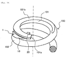
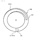
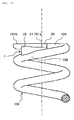
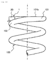
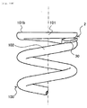
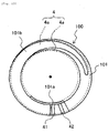
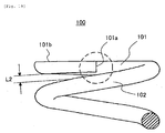
- Fig. 19 is a partially enlarged view showing an upper end side of a Ti spring.
- an end 101 a and a cut flat surface 101 b are formed on a first turn 101 of a Ti spring 100.
- the end 101 a has a sharp edge at a periphery thereof, so that each time the Ti spring 100 repeats contraction and expansion, the terminal cut portion 101 a abuts against a second turn 102 and the second tum 102 undergoes contact abrasion.
- valves for intake and exhaust of an engine of a vehicle use a spring made of Ti. Since such Ti spring for valves performs intense motions of expansion and contraction at high speed, some springs are provided with means that prevents contact and abrasion between a first turn and a second turn.
- United States Patent Specification No. 4,993,376 proposes a spring unit, in which an end of a first turn of a Ti valve spring (valve spring) is insert-molded in a spring seat made of a synthetic resin in order to prevent abutment between the end of the first turn of the valve spring and the second turn.
- valve spring Ti valve spring
- the spring seats are structured such that an annular flange is molded integrally to one end edge of a cylindrical-shaped member, the spring seats, respectively, being fitted onto both ends of the valve spring.
- One of the spring seats is abutted and held by a spring bearing surface (indicates a surface that bears a load of the spring) of a spring retainer, and the other of the spring seats is abutted and held by a spring bearing surface, which is an annular flat surface formed on a cylinder head, through a washer-shaped spring seat.
- the end of the first turn of the valve spring is insert-molded in the spring seat made of a synthetic resin whereby abutment between the end of the first turn of the valve spring and the second turn is prevented, so that it is possible to prevent contact abrasion of the second tum.
- a shoulder surface comprising a circumferentially inclined surface bearing an end of the valve spring is protrusively provided on the spring seat to be made integral therewith.
- the spring seat is intended for a valve spring unit of an internal combustion engine, it is also conceivable to apply the spring seat to a unit, such as vehicular suspension units, provided with a large spring.
- a suspension spring having a large wire diameter involves a large individual dispersion in configuration of both spring ends as compared with the valve spring. Therefore, there is a need of forming a clearance for accommodation of the individual dispersion between the shoulder surface and the second turn by lowering the shoulder surface interposed between an end of a first turn and a second turn of the suspension spring.
- the invention has been thought of in view of the problems and has its object to provide a suspension unit comprising a spring spacer that adopts a simple structure to surely prevent contact between an end of a first turn and a second turn of a spring, which is made of Ti or the like and low in surface hardness, to enable achieving an improvement in durability and to make easy mounting to enable achieving an improvement in productivity, and a vehicle.
- a suspension unit comprising a spring having a first turn and a second turn, a spring bearing and a spring spacer, the spring spacer comprising a contact preventive portion preventing an end of the first turn of the spring from contacting with the second tum, and a holding portion holding the contact preventive portion on the spring or the spring bearing, wherein the holding portion is configured to be free of contact with both the spring and the spring bearing.
- both ends of the spring are held on spring bearing surfaces.
- the contact preventive portion is arranged between the first turn and the second turn of the spring, and/or the contact preventive portion is interposed between the spring bearing and the spring.
- the contact preventive portion comprising a latch being interposed between the spring bearing and the spring, the latch being configured to prevent the contact preventive portion from moving along the spring.
- the latch comprises at least one deformation member configured to be deformed upon application of a load in an axial direction of the spring.
- a thickness of the contact preventive portion is larger than a dimension of a clearance between the first turn and the second turn of the spring, in which the contact preventive portion is press-fitted to be held by the first turn and the second turn.
- the holding portion comprises latch grooves, which are formed on two surfaces of the contact preventive portion and arcuate in cross section to correspond to outer peripheral surfaces of the first turn and the second turn of the spring.
- the thickness of the contact preventive portion is smaller than a dimension of a clearance between the first turn and the second turn of the spring, in which the contact preventive portion is mounted.
- a portion of the contact preventive portion which corresponds to the end of the first turn, is smaller in thickness than the remaining portion.
- the holding portion comprises an abutment piece formed on one side of the contact preventive portion to abut against at least an inner peripheral surface of the second turn of the spring and the abutment piece is configured to abut against an outer peripheral surface of a cylindrical-shaped member inserted into the spring and is configured to hold the contact preventive portion between the first turn and the second turn of the spring, or between the spring bearing and the spring.
- the holding portion comprises an elastic engagement piece provided on the contact preventive portion, the elastic engagement piece surrounds a portion of the spring at least partly, and the elastic engagement piece is configured to hold the contact preventive portion between the first turn and the second turn of the spring, or between the spring bearing and the spring.
- the holding portion comprises an adhesive configured to bond and fix the contact preventive portion to the spring bearing to hold the same between the spring bearing and the spring.
- the holding portion comprises an engagement projection provided on the contact preventive portion, and the contact preventive portion is held between the spring bearing and the spring by engaging the engagement projection with an engagement hole of the spring bearing.
- the contact preventive portion is arcuate to have substantially the same radius of curvature as that of the second turn of the spring, and/or the contact preventive portion is formed lengthy to interpose between the first turn and the second turn of the spring even in the case where the contact preventive portion is moved along the spring.
- a vehicle in particular a motorcycle, comprising a suspension unit according to at least one of the above embodiments.
- Fig. 1 is a side view showing a part of a vehicle (off-road type motorcycle) according to an embodiment.
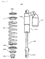
- Figs. 2A to 2C show a suspension unit according to an embodiment, Fig. 2A being a perspective view showing an assembled state, Fig. 2B being an exploded, perspective view, and Fig. 2C being a partially, enlarged view of Fig. 2A.
- the reference numeral 200 denotes a rear arm support of an off-road type motorcycle
- a rear arm bracket 204b is arranged obliquely of a vehicle and downwardly of a vehicle frame 204 to diverge and extend vertically
- an air cleaner 207 is arranged in a space surrounded by a seat, left and right seat rails, and left and right seat stays, which are not shown.
- the air cleaner 207 is constructed such that an element for filtration of an air is arranged in an air cleaner casing 207a.
- a rear arm 210 is pivotally supported by a pivot shaft 211 on a rear and lower end of the rear arm bracket 204b to freely swing up and down, and a rear wheel 212 is joumaled on a rear end of the rear arm 210.
- the rear arm 210 is structured to connect a square-shaped cross pipe 210b between front ends of left and right arm portions 210a, 210a.
- the cross pipe 210b is arranged in a position as close to the rear wheel 212 as possible so as to make a clearance between it and a front edge of the rear wheel minimum whereby a wheel base is shortened and strength and rigidity required for the whole rear arm 210 are ensured.
- a chain casing 205 that covers an upper portion of a drive chain is arranged on the left arm portion 210a.
- a front edge 205a of the chain casing 205 is positioned on an upper surface of the cross pipe 210b.
- a single inverted type suspension unit 214 is arranged between the vehicle frame 204 and the rear arm 210 and on a center line of a vehicle.
- the suspension unit 214 mainly includes a cylinder 215, a piston rod 216, a reservoir tank 217 (see Fig. 2A), a Ti spring (spring) 100, and a linkage 218.
- the cylinder 215 is connected to a bracket 204a on a rear and upper end of the rear arm bracket 204b as shown in Fig. 1. Also, as shown in Figs. 2A to 2C, the cylinder 215 includes a male thread 215a on an outer peripheral surface toward an upper end thereof, and a lock nut 215b and a spring guide (spring bearing) 4, respectively, are threaded on the male thread 215a.
- the spring guide (spring bearing) 4 includes a metallic member having a flange portion 4b, which bears a load of the Ti spring 100, made integral with a cylindrical-shaped trunk portion (cylindrical-shaped member) 4a (see Fig. 10D for the trunk portion 4a and the flange portion 4b), and the trunk portion 4a is provided on an inside thereof with a female thread (not shown), which is threaded on the male thread 215a of the cylinder 215.
- the spring guide 4 is threaded on the male thread 215a to bear a load of the Ti spring 100 (for example, a load of 7500 N at the time of off-road traveling).
- that surface of the flange portion 4b, which abuts against the Ti spring 100 corresponds to "spring bearing surface".
- the piston rod 216 is connected to a piston (not shown) slidably inserted into the cylinder 215 and projects downward from the cylinder 215.
- a piston (not shown) slidably inserted into the cylinder 215 and projects downward from the cylinder 215.
- Mounted to a lower end of the piston rod 216 are a metallic spring guide 216a that pairs with the spring guide 4, load bearing members 216b, 216c that support the metallic spring guide 216a, and a link portion 216d.
- the reservoir tank 217 is communicated to an interior of the cylinder 215 via a pressure oil flow passage (not shown) to accommodate an increase and a decrease in pressure oil volume in the cylinder 215 when the piston rod 216 extends and contracts.
- the Ti spring 100 is exteriorly mounted to the cylinder 215 and the piston rod 216 and held by the pair of the upper and lower spring guides 4, 216a.
- the bias of the Ti spring 100 can be regulated by varying a position, in which the lock nut 215b and the spring guide 4 are clamped together.
- Mounted to the Ti spring 100 is a spring spacer 1 (see Fig. 3), according to the embodiment, described later.
- the linkage 218 includes, as shown in Fig. 1, a pair of left and right first links 220 pivotally mounted to a lower end of the rear arm bracket 204b and a second link 221 pivotally mounted to a lower surface of the cross pipe 210b.
- the piston rod 216 is connected to the rear arm 210 by connecting the link portion 216d of the piston rod 216 to the first links 220 of the linkage 218.
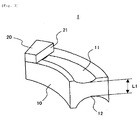
- Fig. 3 is a perspective view showing the spring spacer according to the first embodiment.
- the spring spacer 1 is interposed in a clearance L2 between a first turn 101 and a second turn 102 of the Ti spring 100 shown in Figs. 1 and 19 to prevent an end 101 a of the first turn 101 from contacting with the second turn 102.
- the spring spacer 1 is made separate from and independent of the metallic spring guide and molded from hard rubber to form a contact preventive portion (first contact preventive portion) 10 and a latch (second contact preventive portion) 20 integrally.
- the contact preventive portion 10 is arcuate to have substantially the same radius of curvature as that of the first turn 101 and the second turn 102 of the Ti spring 100.
- the contact preventive portion 10 is formed on upper and lower surfaces thereof, respectively, with latch grooves (holding portions) 11, 12, which are arcuate in cross section to correspond to outer peripheral surfaces of the first turn 101 and the second turn 102 of the Ti spring 100.
- the contact preventive portion 10 is small in thickness on that tip end side thereof, on which the latch 20 is provided, and large in thickness on a rear end side thereof (see Fig. 4C), and a central portion of the latch grooves 11, 12 on the rear end side has a larger thickness L1 than that of the clearance L2 between the first turn 101 and the second turn 102 of the Ti spring 100.
- the latch 20 is in the form of a rectangular-shaped block projection to include an abutment surface 21 facing toward the latch groove 11 on the upper surface of the contact preventive portion 10.
- the latch 20 When mounted to the Ti spring 100, the latch 20 has the abutment surface 21 abutting against the end 101 a of the first turn 101 to prevent the spring spacer 1 from moving toward the second turn 102 (see Fig. 4C).
- a space toward the first turn 101 is narrowed heightwise, so that movement of the spring spacer 1 toward the first turn 101 is prevented by the latch 20.
- the latch 20 is interposed between the spring guide 4 and the second tum 102 of the Ti spring 100 to serve as the second contact preventive portion that prevents the end 101 a of the first turn 101 from contacting with the second turn 102.
- a material that forms the spring spacer 1 Demanded of a material of the spring spacer 1 are properties, such as antifriction, owing to which the spring spacer does not undergo abrasion easily even when subjected to vibrations in a state of being interposed between the first turn 101 and the second turn 102 of the Ti spring 100, and elasticity capable of accommodating an error in the case where the clearance L2 between the first turn 101 and the second tum 102 is smaller than a predetermined value.
- sufficient antifriction, hardness, and elasticity could be obtained when the spring spacer 1 was experimentally manufactured by hard rubber that forms a chain slider generally used as a part for motorcycles.
- Figs. 4A to 4C are perspective views showing respective processes until the spring spacer according to the embodiment is mounted to the Ti spring.
- the contact preventive portion 10 of the spring spacer 1 is arranged in a location, in which a spacing between the first turn 101 and the second turn 102 of the Ti spring 100 is large, and the spring spacer 1 is pushed toward the first turn 101 while the respective latch grooves 11, 12 (see Fig. 3) are caused to go along the first turn 101 and the second turn 102.
- the latch 20 of the spring spacer 1 is retreated inside the spring spacer 1 so as not to be interposed between the first turn 101 and the second turn 102.
- the contact preventive portion 10 of the spring spacer 1 is pushed intact against the bias of the first turn 101 and the second turn 102 of the Ti spring 100 and the spring spacer 1 is corrected in posture when the latch 20 passes by the end 101 a of the first turn 101.
- Figs. 5, 6A, 6B, 6C, and 6D show a state, in which the spring spacer 1 is mounted to the Ti spring 100.
- Fig. 5 is a plan view
- Fig. 6A is a front view
- Fig. 6B is a left side view
- Fig. 6C is a right side view
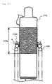
- Fig. 6D is a front view showing a state, in which the Ti spring contracts.
- the rear arm 210 moves downward and the Ti spring 100 is put in an extended state.
- the rear arm 210 moves upward and the Ti spring 100 is put in a contracted state.
- the spring spacer 1 according to the embodiment is press fitted and held between the first turn 101 and the second turn 102 at all times irrespective of an extended state of the Ti spring 100 shown in Figs. 6A to 6C and a contracted state of the Ti spring 100 shown in Fig. 6D and prevents contact between the end 101 a of the first turn 101 and the second tum 102.
- the spring spacer 1 is of a very simple structure to mainly include the contact preventive portion 10 and the latch 20, thus surely preventing contact between the end 101 a of the first turn 101 and the second turn 102 of the Ti spring 100 to enable preventing contact and abrasion of the second turn 102. Thereby, it is possible to sharply improve the Ti spring 100, which is low in surface hardness, in durability.
- the latch grooves 11, 12 serving as holding portions are shaped not to contact with both the flange portion (spring bearing surface) 4b of the spring guide 4 and the Ti spring 100 all the time, for example, shaped not to be interposed between the flange portion 4b and the Ti spring 100 all the time. Thereby, it is possible to mount the spring spacer 1 to the Ti spring 100 at any time irrespective of before and after the Ti spring 100 is mounted to the suspension unit 214.
- the thickness L1 of the contact preventive portion 10 is made larger than the clearance L2 between the first turn 101 and the second turn 102 of the Ti spring 100.
- the spring spacer 1 can be mounted to the Ti spring 100 by easy means in which the contact preventive portion 10 is press fitted into the clearance L2 in a manual work.
- by making the thickness L1 of the contact preventive portion 10 larger than the clearance L2 between the first turn 101 and the second turn 102 of the Ti spring 100 individual dispersion in shape with respect to both ends of the Ti spring 100 can be accommodated.
- the contact preventive portion 10 of the spring spacer 1 is arcuate to have substantially the same radius of curvature as that of the first turn 101 and the second turn 102 of the Ti spring 100 whereby it is possible to make the spring spacer 1 follow the arcuate shape of the first turn 101 and the second turn 102 of the Ti spring 100.
- the spring spacer 1 does not extend outside the first turn 101 and the second turn 102 and the spring spacer 1 can be formed from a necessity minimum material.
- the spring guide 4 can posses durability for a very large load of the Ti spring 100.
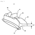
- Fig. 7 is a perspective view showing the spring spacer according to the second embodiment.
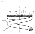
- the spring spacer 2 mainly includes an abutment piece (holding portion) 31 formed contiguous to a side of a plate-shaped contact preventive portion 30 to extend downward, and latches 41, 42 comprising two piece members and provided protrusively at a predetermined interval on a tip end side of the contact preventive portion 30.
- the thickness L3 of the contact preventive portion 30 is made thinner than the clearance L2 between the first turn 101 and the second turn 102 of the Ti spring 100 shown in Fig. 19, thus making it possible to insert and arrange the contact preventive portion 30 into the clearance L2 without any resistance.
- the contact preventive portion 30 is arcuate to have substantially the same radius of curvature as that of the first turn 101 and the second turn 102 of the Ti spring 100 in the same manner as in the first embodiment and the abutment piece 31 formed contiguous to the contact preventive portion 30 is also arcuate to have the same radius of curvature as that of the second turn 102.
- a continuous, inner peripheral surface 32 of the contact preventive portion 30 and the abutment piece 31 is arcuate in cross section to correspond to an inner peripheral surface of the second turn 102 of the Ti spring 100, thus enabling placing the spring spacer 2 on the second turn 102 of the Ti spring 100 in a stable state.
- a stepwise recess 33 is provided on that portion of the contact preventive portion 30, which corresponds to the end 101 a of the first turn 101, and the recess 33 is made smaller in thickness than the remaining portion.
- the pair of the latches 41, 42 include the piece members, which are different in height and thickness from each other, and the latch 41 is made large in height and small in thickness as compared with the latch 42, and susceptible to deformation upon application of a load from above.
- the latch 41 is made substantially triangular in cross section to have a large thickness on a base side thereof whereby it is made hard to deform upon application of a load from laterally. Such latch 41 abuts against the end 101 a of the first turn 101 of the Ti spring 100 to prevent the spring spacer 2 from moving toward the second tum 102 (see Fig. 8B).
- the latch 42 is made small in height and large in thickness as compared with the latch 41, and susceptible to deformation upon application of a load from above while deformation is less than that of the latch 41.
- the spring guide 4 shown in Fig. 10D is mounted on the cut flat surface 101 b of the first turn 101 of the Ti spring 100, a space toward the first turn 101 is narrowed heightwise, so that movement of the spring spacer 2 toward the first turn 101 is prevented by the latch 42.
- Figs. 8A and 8B are perspective views showing respective processes until the spring spacer according to the embodiment is mounted to the Ti spring.
- the spring spacer 2 is arranged inside the Ti spring 100, and as shown in Fig. 8B, the contact preventive portion 30 of the spring spacer 2 is inserted into the clearance L2 between the first turn 101 and the second turn 102 of the Ti spring 100.
- Figs. 9, 10A, 10B, and 10C show a temporarily latched state of the spring spacer 2.
- Fig. 9 is a plan view
- Fig. 10A is a front view
- Fig. 10B is a left side view
- Fig. 10C is a right side view.
- mounting of the spring spacer 2 is completed by mounting the spring guide 4 to the first turn 101 of the Ti spring 100. That is, a trunk portion 4a of the spring guide 4 is pushed onto an inner periphery of the first turn 101 of the Ti spring 100 to cause a torus-shaped flange portion 4b to abut against the cut flat surface 101 b of the first turn 101 of the Ti spring 100.
- the trunk portion 4a of the spring guide 4 holds down the spring spacer 2 from inside the Ti spring 100, so that coming-out inside the Ti spring 100 is prevented. That is, the abutment piece 31 is held down by the trunk portion 4a of the spring guide 4 to hold the spring spacer 2 indirectly. Also, the abutment piece 31 abuts against the inner peripheral surface of the second turn 102 to prevent coming-out of the spring spacer 2 outside the Ti spring 100.
- the first turn 101 of the Ti spring 100 abuts against the contact preventive portion 30 of the spring spacer 2 to prevent contact between the end 101 a of the first turn 101 and the second turn 102.
- the stepwise recess 33 is formed on that portion of the contact preventive portion 30, which corresponds to the end 101 a, whereby contact between the end 101 a and the contact preventive portion 30 is prevented.
- the thickness L3 of the contact preventive portion 30 is made smaller than that clearance L2 between the first turn 101 and the second tum 102 of the Ti spring 100, in which the contact preventive portion 30 is mounted.
- the spring spacer 2 it is possible to arrange the spring spacer 2 in the clearance L2 between the first turn 101 and the second turn 102 of the Ti spring 100 without any resistance.
- the abutment piece 31 of the spring spacer 2 can be easily mounted to the Ti spring 100 by using the existing spring guide 4 to hold down the abutment piece 31 of the spring spacer from inside.
- the spring spacer 2 involves a possibility that when the Ti spring 100 contracts and the clearance L2 becomes narrow, the end 101 a of the first turn 101 contacts with the contact preventive portion 30. Even in such case, the end 101 a can be prevented from contacting with the contact preventive portion 30 since the stepwise recess 33 is formed on that portion of the contact preventive portion 30, which corresponds to the end 101 a.
- the latches 41, 42 include a piece member susceptible to deformation upon application of a load from above. Therefore, even in the case where the latches 41, 42 of the spring spacer 2 project from the end 101 a of the first turn 101 of the Ti spring 100 by virtue of dimensional error of the Ti spring 100, the spring guide 4 can be fitted onto the first turn 101 of the Ti spring 100 without a gap by flexibly deforming the latches 41, 42.
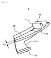
- Fig. 11 is a perspective view showing the spring spacer according to the third embodiment.
- the same parts as those of the second embodiment described above are denoted by the same reference numerals as those therein, and a detailed explanation therefor is omitted.
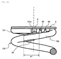
- a spring spacer 3 mainly includes an elastic engagement piece 51 formed contiguous to a side of a plate-shaped contact preventive portion 50 to extend downward to bend outward, and latches 41, 42 provided protrusively at a predetermined interval on a tip end side of the contact preventive portion 50 to be similar to those in the second embodiment.
- a thickness L4 of the contact preventive portion 50 is made thinner than the clearance L2 between the first turn 101 and the second turn 102 of the Ti spring 100 shown in Fig. 19, thus making it possible to insert and arrange the contact preventive portion 50 into the clearance L2 without any resistance.
- the contact preventive portion 50 is arcuate to have substantially the same radius of curvature as that of the first turn 101 and the second turn 102 of the Ti spring 100 in the same manner as in the first embodiment.
- an inner peripheral surface 51 a of the elastic engagement piece 51 is arcuate in cross section to correspond to an inner peripheral surface of the second turn 102 of the Ti spring 100, thus enabling elastically holding the inner peripheral surface of the second turn 102. Further, the inner peripheral surface 51 a of the elastic engagement piece 51 is a little smaller in radius of curvature than the inner peripheral surface of the second tum 102 of the Ti spring 100, so that even in the case where a dimensional error appears in the diameter of the second turn 102, a sufficient holding force is obtained.
- a stepwise recess 52 is provided on that portion of the contact preventive portion 50, which corresponds to the end 101a of the first turn 101, and the recess 52 is made smaller in thickness than the remaining portion.
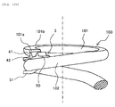
- Figs. 12A, 12B, and 12C are perspective views showing respective processes until the spring spacer according to the embodiment is mounted to the Ti spring.
- the spring spacer 3 is arranged inside the Ti spring 100.
- the contact preventive portion 50 of the spring spacer 3 is inserted into the clearance L2 between the first turn 101 and the second turn 102 of the Ti spring 100, and the elastic engagement piece 51 of the spring spacer 3 is caused to elastically engage with the inner peripheral surface of the second turn 102 of the Ti spring 100, thus temporarily latching the spring spacer 3 thereon.
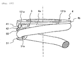
- Figs. 13, 14B, and 14C show a temporarily latched state of the spring spacer 3.
- Fig. 13 is a plan view
- Fig. 14B is a left side view
- Fig. 14C is a right side view.
- the first turn 101 of the Ti spring 100 abuts against the contact preventive portion 50 of the spring spacer 3 to prevent contact between the end 101 a of the first turn 101 and the second tum 102.
- the stepwise recess 52 is formed on that portion of the contact preventive portion 50, which corresponds to the end 101 a, whereby contact between the end 101 a and the contact preventive portion 50 is prevented.
- the thickness L4 of the contact preventive portion 50 is made smaller than that clearance L2 between the first turn 101 and the second tum 102 of the Ti spring 100, in which the contact preventive portion 50 is mounted. Thereby, it is possible in the same manner as in the second embodiment to arrange the spring spacer 3 in the clearance L2 between the first turn 101 and the second turn 102 of the Ti spring 100 without any resistance.
- the spring spacer 3 by elastically engaging the elastic engagement piece 51 with the inner peripheral surface of the second tum 102 of the Ti spring 100, it is possible to stably hold the spring spacer 3 in the clearance L2 between the first turn 101 and the second turn 102 of the Ti spring 100. Thereby, mounting of the spring spacer 3 to the Ti spring 100 is made very easy.
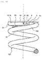
- Fig. 15 is a front view showing a state, in which the spring spacer according to the fourth embodiment is mounted to the Ti spring.
- a spring spacer 6 includes a first contact preventive portion 61 in the form of a thin sheet piece, and a second contact preventive portion (latch) 62 in the form of a block, which portions are molded from a synthetic resin to be made integral.
- the spring spacer 6 includes a holding portion made of an adhesive to bond the second contact preventive portion 62 to the trunk portion 4a and the flange portion 4b of the spring guide 4.
- the thickness of the second contact preventive portion 62 may be made larger than a dimension of that clearance between the spring guide 4 and the second turn 102 of the Ti spring 100, in which the second contact preventive portion 62 is mounted, and held in the clearance between the spring guide 4 and the second turn 102 by press fitting the second contact preventive portion 62 thereinto.
- the first contact preventive portion 61 of the spring spacer 6 is interposed between the first turn 101 and the second turn 102 of the Ti spring 100 to enable preventing the end 101 a of the first turn 101 from contacting with the second turn 102. Also, since only the spring spacer 6 is formed from the synthetic resin and the spring guide 4 is formed from metal, the spring guide 4 can posses durability for a very large load of the Ti spring 100.
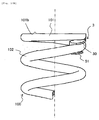
- Fig. 16 is a front view showing a state, in which the spring spacer according to the fifth embodiment is mounted to the Ti spring.
- a spring spacer 7 includes a block-shaped member molded from a synthetic resin, and separated from and independent of a metallic spring guide 4 that holds the first turn 101 of the Ti spring 100.
- An engagement projection 71 serving as a holding portion is molded on an upper surface of the spring spacer 7.
- a multiplicity of engagement holes 4c, 4c, ... are drilled on the flange portion (spring bearing surface) 4b of the spring guide 4 to extend along a circumference thereof.
- such structure causes the spring spacer 7 to interpose between the spring guide 4 and the second turn 102 of the Ti spring 100 to enable preventing the end 101 a of the first turn 101 from contacting with the second turn 102.
- an optimum engagement hole 4c out of the multiplicity of engagement holes 4c, 4c, ... drilled on the flange portion 4b of the spring guide 4 is selected to make it possible to mount the spring spacer 7 in an optimum position. Further, since only the spring spacer 6 is formed from the synthetic resin and the spring guide 4 is formed from metal, the spring guide 4 can posses durability for a very large load of the Ti spring 100.
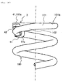
- Fig. 17 is a front view showing a state, in which the spring spacer according to the sixth embodiment is mounted to the Ti spring.
- a spring spacer 8 includes a block-shaped contact preventive portion 81 and an elastic engagement piece 82 serving as a holding portion, the contact preventive portion and the elastic engagement piece being molded from a synthetic resin to be made integral.
- the contact preventive portion 81 is structured in substantially the same manner as in the spring spacer 7 according to the sixth embodiment.
- the elastic engagement piece 82 is made arcuate to elastically hold the inner peripheral surface of the second turn 102 of the Ti spring 100.
- an inner peripheral surface of the elastic engagement piece 82 is a little smaller in radius of curvature than the inner peripheral surface of the second turn 102 of the Ti spring 100, so that even in the case where a dimensional error appears in the diameter of the second turn 102, a sufficient holding force is obtained.
- such structure causes the spring spacer 8 to interpose between the spring guide 4 and the second turn 102 of the Ti spring 100 to enable preventing the end 101 a of the first turn 101 from contacting with the second turn 102.
- the elastic engagement piece 82 serving as a holding portion is shaped not to contact with both the flange portion (spring bearing surface) 4b of the spring guide 4 and the Ti spring 100 all the time. Thereby, it is possible to mount the spring spacer 1 to the Ti spring 100 at any time irrespective of before and after the Ti spring 100 is mounted to the suspension unit 214.
- the spring guide 4 can posses durability for a very large load of the Ti spring 100.
- the spring spacer 8 by elastically engaging the elastic engagement piece 82 with the inner peripheral surface of the second tum 102 of the Ti spring 100, it is possible to stably hold the spring spacer 8 between the spring guide 4 and the second tum 102 of the Ti spring 100. Thereby, mounting of the spring spacer 8 to the Ti spring 100 is made very easy.
- Fig. 18 is a front view showing a state, in which the spring spacer according to the seventh embodiment is mounted to the Ti spring.
- a spring spacer 9 includes an elastic engagement piece (holding member) 92 formed contiguous to a side of a plate-shaped contact preventive portion 91 to extend downward to bend outward, and latches 93, 94 provided protrusively at a predetermined interval on a tip end side of the contact preventive portion 91 to be similar to those in the second and third embodiments.
- the contact preventive portion 91 is made lengthy to interpose between the first turn 101 and the second turn 102 of the Ti spring 100 even in the case where the contact preventive portion 91 is moved along the Ti spring 100, thus preventing the end 101 a of the first turn 101 from contacting with the second turn 102.
- the spring spacer 9 enables the contact preventive portion 91 to interpose between the first turn 101 and the second turn 102 of the Ti spring 100 all the time. Thereby, it is possible to surely prevent the end 101 a of the first turn 101 of the Ti spring 100 from contacting with the second turn 102.
- the invention is not limited to the spring spacers, suspension springs, suspension units, and vehicles according to the respective embodiments.
- a spring to which the spring spacer is applied, is not limited to the Ti spring but can prevent abrasion of a spring, which is not made of Ti and low in surface hardness.
- the spring spacer can be applied to a spring, which is large to some extent and intended for other uses than a use for suspension, and also applied to other devices than suspension units.
- “Vehicle”, to which the present suspension unit and spring spacer is applicable, includes motorcycles and automobiles.
- “motorcycle” means a motorcycle and includes bicycles with a motor (motorbike) and scooters, “motorcycle” specifically meaning a vehicle capable of turning with a vehicle body inclined.
- included in “motorcycle” is a vehicle, of which at least one of a front wheel and a rear wheel is made two or more in number and which belongs to tricycles, four-wheel cars (or more) in terms of the number of tires.
- the present spring spacer is applicable to a so-called saddle-ride type vehicle, such as snowmobile, four-wheel buggy (ATV: All Terrain Vehicle), etc., in addition to "motorcycle”.
- the spring spacer is interposed between a first turn and a second turn of a Ti spring
- the spring spacer is preferably interposed between first turns and second turns at both ends of the Ti spring.
- a spring spacer comprising a contact preventive portion that prevents an end of a first turn of a spring, of which both ends are held on spring bearing surfaces, from contacting with a second turn, a holding portion that holds the contact preventive portion directly or indirectly on the spring or the spring bearing surface, and wherein the holding portion is shaped not to contact with both the spring bearing surface and the spring all the time.
- the spring spacer according to said teaching structured in the manner described above adopts a simple structure to surely prevent contact between an end of a first turn and a second turn of a spring, which is made of Ti or the like and low in surface hardness, to enable achieving an improvement in durability.
- the holding portion is shaped not to contact with both the spring bearing surface and the spring all the time whereby the spring spacer can be beforehand or after the fact mounted to the spring by easy means such as press fitting or engagement, thereby enabling achieving an improvement in productivity.
- the contact preventive portion interposes between the first turn and the second turn of the spring to prevent the end of the first turn from contacting with the second tum.
- the contact preventive portion interposes between the spring bearing surface and the spring to prevent the end of the first turn from contacting with the second turn.
- the construction includes a first contact preventive portion that interposes between the first turn and the second turn of the spring to prevent the end of the first turn from contacting with the second turn, and a second contact preventive portion that interposes between the spring bearing surface and the spring to prevent the end of the first turn from contacting with the second turn.
- the construction includes the contact preventive portion that interposes between the first turn and the second turn of the spring to prevent the end of the first turn from contacting with the second turn, and a latch that interposes between the spring bearing surface and the spring to prevent the contact preventive portion from moving along the spring.
- the construction includes the contact preventive portion that interposes between the first turn and the second turn of the spring to prevent the end of the first turn from contacting with the second turn, and a latch that interposes between the spring bearing surface and the spring to prevent the contact preventive portion from moving along the spring, and the latch includes one or two piece members susceptible to deformation upon application of a load from above.
- the construction includes the thickness of the contact preventive portion is made larger than a dimension of that clearance between the first turn and the second turn of the spring, in which the contact preventive portion is mounted, the holding portion includes latch grooves, which are formed on two surfaces of the contact preventive portion, respectively, and arcuate in cross section to correspond to outer peripheral surfaces of the first turn and the second turn of the spring, and the contact preventive portion is press fitted and held between the first turn and the second turn of the spring.
- the thickness of the contact preventive portion is made smaller than a dimension of that clearance between the first turn and the second turn of the spring, in which the contact preventive portion is mounted.
- the thickness of the contact preventive portion is made smaller than a dimension of that clearance between the first turn and the second turn of the spring, in which the contact preventive portion is mounted, and that portion of the contact preventive portion, which corresponds to the end of the first turn, is made smaller in thickness than the remaining portion.
- the holding portion includes an abutment piece formed on one side of the contact preventive portion to abut against at least an inner peripheral surface of the second turn of the spring and the abutment piece is caused to abut against an outer peripheral surface of a cylindrical-shaped member inserted into the spring to thereby hold the contact preventive portion between the first turn and the second turn of the spring, or between the spring bearing surface and the spring.
- the holding portion includes an elastic engagement piece provided on the contact preventive portion and the spring is held by the elastic engagement piece to hold the contact preventive portion between the first turn and the second turn of the spring, or between the spring bearing surface and the spring.
- the holding portion includes an adhesive to bond and fix the contact preventive portion to the spring bearing surface to hold the same between the spring bearing surface and the spring.
- the holding portion includes an engagement projection provided on the contact preventive portion and the contact preventive portion is held between the spring bearing surface and the spring by engaging the engagement projection with an engagement hole formed on the spring bearing surface.
- the contact preventive portion is arcuate to have substantially the same radius of curvature as that of the second turn of the spring.
- the contact preventive portion is made lengthy to interpose between the first turn and the second turn of the spring even in the case where the contact preventive portion is moved along the spring, thus preventing the end of the first turn from contacting with the second turn.
- the description further discloses an embodiment of a spring having any one of the above spring spacers interposed between the first turn and the second turn, or between the spring bearing surface and the second turn, or between the both.
- the description further discloses an embodiment of a suspension spring having any one of the above spring spacers interposed between the first turn and the second turn, or between the spring bearing surface and the second turn, or between the both.
- the description further discloses an embodiment of a unit having any one of the spring spacers interposed between the first turn and the second tum of a spring, or between the spring guide and the second turn, or between the both.
- the description further discloses an embodiment of a suspension unit having any one of the above spring spacers interposed between the first turn and the second turn of a suspension spring, or between the spring guide and the second turn, or between the both.
- the description further discloses an embodiment of a vehicle with a suspension unit having any one of the above spring spacers interposed between the first turn and the second turn of a suspension spring, or between the spring guide and the second tum, or between the both.
- the spring spacer when used for a spring that forms various units, or a suspension spring that forms a suspension unit of a vehicle, it is possible to prevent contact abrasion of a second turn of the spring, the suspension spring, the unit, the suspension unit, and the vehicle, and to achieve an improvement in productivity.
- the description above discloses a particularly preferred embodiment in order to provide a spring spacer capable of improving durability by preventing abrasion of a spring, which is made of Ti or the like and low in surface hardness, and a vehicle.
- a construction includes a contact preventive portion 10 interposed between the first turn 101 and the second tum 102 of the Ti spring 100 to prevent the end 101 a of the first turn 101 from contacting with the second turn 102, and a latch 20 that abuts against the end 101 a of the first turn 101 to prevent the contact preventive portion 10 from moving toward the second turn 102.
Landscapes
- Engineering & Computer Science (AREA)
- General Engineering & Computer Science (AREA)
- Mechanical Engineering (AREA)
- Springs (AREA)
- Vehicle Body Suspensions (AREA)
- Axle Suspensions And Sidecars For Cycles (AREA)
Abstract
Description
- The present invention relates to a suspension unit comprising a spring spacer capable of preventing abrasion of a spring, which is made of Ti or the like and low in surface hardness, and a vehicle.
- In recent years, motorcycles used for specific applications such as race or the like adopt springs, which are made of Ti to be lightweight as compared with conventional springs made of Fe, for suspension units or the like. For example, in case of adopting a Ti spring for a suspension unit, a weight can be reduced by 200 to 500 g (by spring constant) in comparison with conventional springs made of Fe (see United States Patent Specification No. 4,993,376).
- However, while Ti springs are advantageous to be very lightweight, they involve a problem that they are liable to wear and low in durability since their surface hardness is as low as Ti:Hv420 as compared with Fe:Hv550, and accordingly are very expensive parts that must be replaced in 1 to 2 races in case of being used as, for example, suspension units for race motorcycles.
- The problem of such Ti springs is described in further detail. Fig. 19 is a partially enlarged view showing an upper end side of a Ti spring. In the figure, an
end 101 a and a cutflat surface 101 b are formed on afirst turn 101 of aTi spring 100. Among these, theend 101 a has a sharp edge at a periphery thereof, so that each time the Tispring 100 repeats contraction and expansion, theterminal cut portion 101 a abuts against asecond turn 102 and thesecond tum 102 undergoes contact abrasion. - In addition, some valves for intake and exhaust of an engine of a vehicle use a spring made of Ti. Since such Ti spring for valves performs intense motions of expansion and contraction at high speed, some springs are provided with means that prevents contact and abrasion between a first turn and a second turn.
- For example, United States Patent Specification No. 4,993,376 proposes a spring unit, in which an end of a first turn of a Ti valve spring (valve spring) is insert-molded in a spring seat made of a synthetic resin in order to prevent abutment between the end of the first turn of the valve spring and the second turn.
- The spring seats are structured such that an annular flange is molded integrally to one end edge of a cylindrical-shaped member, the spring seats, respectively, being fitted onto both ends of the valve spring. One of the spring seats is abutted and held by a spring bearing surface (indicates a surface that bears a load of the spring) of a spring retainer, and the other of the spring seats is abutted and held by a spring bearing surface, which is an annular flat surface formed on a cylinder head, through a washer-shaped spring seat.
- With such construction, the end of the first turn of the valve spring is insert-molded in the spring seat made of a synthetic resin whereby abutment between the end of the first turn of the valve spring and the second turn is prevented, so that it is possible to prevent contact abrasion of the second tum.
- Also, there is disclosed a further embodiment of the spring unit, in which a shoulder surface comprising a circumferentially inclined surface bearing an end of the valve spring is protrusively provided on the spring seat to be made integral therewith. With such construction, the shoulder surface interposes between the end of the first turn and the second turn of the valve spring to enable preventing contact abrasion of the second turn.
- While the spring seat is intended for a valve spring unit of an internal combustion engine, it is also conceivable to apply the spring seat to a unit, such as vehicular suspension units, provided with a large spring. Here, a suspension spring having a large wire diameter involves a large individual dispersion in configuration of both spring ends as compared with the valve spring. Therefore, there is a need of forming a clearance for accommodation of the individual dispersion between the shoulder surface and the second turn by lowering the shoulder surface interposed between an end of a first turn and a second turn of the suspension spring.
- However, there is caused a problem that the clearance for accommodation of the individual dispersion permits the spring seat to rotate at the time of assembling of a suspension unit to cause deviation of relative positions of the shoulder surface and the suspension spring, thus leading to insufficient demonstration of the contact preventive function of the shoulder surface.
- In this case, while it is also conceivable that a worker deliberately performs assembly so as to prevent rotation of the spring seat at the time of assembling of a suspension unit, there is caused a problem of a decrease in productivity because of the necessity of time and labor in work.
- Also, in this case, it is also conceivable to prepare several kinds of the spring seats formed with the shoulder surfaces of different heights and to selectively assemble the several kinds of the spring seats in conformity to individual dispersion involved in suspension springs. However, there is caused a problem of a decrease in productivity because of the necessity of a work of temporarily mounting the several kinds of the spring seats and selecting an optimum spring seat conformed to its individual dispersion.
- On the other hand, in the case where an end of a first turn of a suspension spring is insert-molded in the spring seat made of a synthetic resin, the problem described above is not caused but the process of molding the spring seat in a large-sized suspension spring becomes complex with the result that there is caused a problem of a decrease in productivity.
- The invention has been thought of in view of the problems and has its object to provide a suspension unit comprising a spring spacer that adopts a simple structure to surely prevent contact between an end of a first turn and a second turn of a spring, which is made of Ti or the like and low in surface hardness, to enable achieving an improvement in durability and to make easy mounting to enable achieving an improvement in productivity, and a vehicle.
- This objective is solved in an inventive manner by a suspension unit comprising a spring having a first turn and a second turn, a spring bearing and a spring spacer, the spring spacer comprising a contact preventive portion preventing an end of the first turn of the spring from contacting with the second tum, and a holding portion holding the contact preventive portion on the spring or the spring bearing, wherein the holding portion is configured to be free of contact with both the spring and the spring bearing.
- Preferably, both ends of the spring are held on spring bearing surfaces.
- Further, preferably the contact preventive portion is arranged between the first turn and the second turn of the spring, and/or the contact preventive portion is interposed between the spring bearing and the spring.
- Still further, preferably the contact preventive portion comprising a latch being interposed between the spring bearing and the spring, the latch being configured to prevent the contact preventive portion from moving along the spring.
- Preferably, the latch comprises at least one deformation member configured to be deformed upon application of a load in an axial direction of the spring.
- Beneficially, a thickness of the contact preventive portion is larger than a dimension of a clearance between the first turn and the second turn of the spring, in which the contact preventive portion is press-fitted to be held by the first turn and the second turn.
- Further, beneficially the holding portion comprises latch grooves, which are formed on two surfaces of the contact preventive portion and arcuate in cross section to correspond to outer peripheral surfaces of the first turn and the second turn of the spring.
- Still further, beneficially the thickness of the contact preventive portion is smaller than a dimension of a clearance between the first turn and the second turn of the spring, in which the contact preventive portion is mounted.
- Preferably, a portion of the contact preventive portion, which corresponds to the end of the first turn, is smaller in thickness than the remaining portion.
- Further, preferably the holding portion comprises an abutment piece formed on one side of the contact preventive portion to abut against at least an inner peripheral surface of the second turn of the spring and the abutment piece is configured to abut against an outer peripheral surface of a cylindrical-shaped member inserted into the spring and is configured to hold the contact preventive portion between the first turn and the second turn of the spring, or between the spring bearing and the spring.
- Still further, preferably the holding portion comprises an elastic engagement piece provided on the contact preventive portion, the elastic engagement piece surrounds a portion of the spring at least partly, and the elastic engagement piece is configured to hold the contact preventive portion between the first turn and the second turn of the spring, or between the spring bearing and the spring.
- Beneficially, the holding portion comprises an adhesive configured to bond and fix the contact preventive portion to the spring bearing to hold the same between the spring bearing and the spring.
- Further, beneficially the holding portion comprises an engagement projection provided on the contact preventive portion, and the contact preventive portion is held between the spring bearing and the spring by engaging the engagement projection with an engagement hole of the spring bearing.
- Preferably, the contact preventive portion is arcuate to have substantially the same radius of curvature as that of the second turn of the spring, and/or the contact preventive portion is formed lengthy to interpose between the first turn and the second turn of the spring even in the case where the contact preventive portion is moved along the spring.
- The objective is further solved in an inventive manner by a vehicle, in particular a motorcycle, comprising a suspension unit according to at least one of the above embodiments.
- In the following, the present invention is explained in greater detail with respect to several embodiments thereof in conjunction with the accompanying drawings, wherein:
- Fig. 1
- is a side view showing a part of a vehicle (off-road type motorcycle) according to an embodiment;
- Fig. 2A
- is a perspective view showing a suspension unit, according to the embodiment, in an assembled state;
- Fig. 2B
- is an exploded, perspective view showing the suspension unit;
- Fig. 2C
- is a partially, enlarged view of Fig. 2A;
- Fig.3
- is a perspective view showing a spring spacer according to a first embodiment;
- Fig. 4A
- is a perspective view showing a first process until the spring spacer is mounted to a Ti spring;
- Fig. 4B
- is also a perspective view showing a second process until the spring spacer is mounted to the Ti spring;
- Fig. 4C
- is also a perspective view showing a third process until the spring spacer is mounted to the Ti spring;
- Fig. 5
- is a plan view showing a state, in which the spring spacer is mounted to the Ti spring;
- Fig. 6A
- is a front view showing a state similady, in which the spring spacer is mounted to the Ti spring;
- Fig. 6B
- is a left side view showing a state similarly, in which the spring spacer is mounted to the Ti spring;
- Fig. 6C
- is a right side view showing a state, in which the spring spacer is mounted to the Ti spring similarly;
- Fig. 6D
- is a front view showing a state, in which the Ti spring contracts;
- Fig.7
- is a perspective view showing a spring spacer according to a second embodiment;
- Fig. 8A
- is a perspective view showing a first process until the spring spacer is mounted to the Ti spring;
- Fig. 8B
- is also a perspective view showing a second process until the spring spacer is mounted to the Ti spring;
- Fig. 9
- is a plan view showing a state, in which the spring spacer is mounted to the Ti spring;
- Fig. 10A
- is a front view showing a state similarly, in which the spring spacer is mounted to the Ti spring;
- Fig. 10B
- is a left side view showing a state, in which the spring spacer is mounted to the Ti spring similarly;
- Fig. 10C
- is a right side view showing a state, in which the spring spacer is mounted to the Ti spring similarly;
- Fig. 10D
- is an enlarged view showing a state, in which the spring spacer is mounted to the Ti spring similarly;
- Fig. 11
- is a perspective view showing a spring spacer according to a third embodiment;
- Fig. 12A
- is a perspective view showing a first process until the spring spacer is mounted to the Ti spring;
- Fig. 12B
- is also a perspective view showing a second process until the spring spacer is mounted to the Ti spring;
- Fig. 12C
- is also a perspective view showing a third process until the spring spacer is mounted to the Ti spring;
- Fig. 13
- is a plan view showing a state, in which the spring spacer is mounted to the Ti spring;
- Fig. 14A
- is a front view showing a state, in which the spring spacer is mounted to the Ti spring similarly;
- Fig. 14B
- is a left side view showing a state, in which the spring spacer is mounted to the Ti spring similarly;
- Fig. 14C
- is a right side view showing a state, in which the spring spacer is mounted to the Ti spring similarly;
- Fig. 15
- is a front view showing a state, in which a spring spacer according to a fourth embodiment is mounted to the Ti spring;
- Fig. 16
- is a front view showing a state, in which a spring spacer according to a fifth embodiment is mounted to the Ti spring;
- Fig. 17
- is a front view showing a state, in which a spring spacer according to a sixth embodiment is mounted to the Ti spring;
- Fig. 18
- is a front view showing a state, in which a spring spacer according to a seventh embodiment is mounted to the Ti spring; and
- Fig. 19
- is a partially enlarged view showing an upper end side of a Ti spring.
- First, a suspension unit, a spring spacer, a suspension spring, and a vehicle according to a first embodiment will be described with reference to the drawings. First, an embodiment of a suspension unit and a vehicle, in which the present spring spacer is provided for a suspension spring, will be described with reference to Fig. 1.
- Fig. 1 is a side view showing a part of a vehicle (off-road type motorcycle) according to an embodiment. Also, Figs. 2A to 2C show a suspension unit according to an embodiment, Fig. 2A being a perspective view showing an assembled state, Fig. 2B being an exploded, perspective view, and Fig. 2C being a partially, enlarged view of Fig. 2A.
- In Fig. 1, the
reference numeral 200 denotes a rear arm support of an off-road type motorcycle, arear arm bracket 204b is arranged obliquely of a vehicle and downwardly of avehicle frame 204 to diverge and extend vertically, and anair cleaner 207 is arranged in a space surrounded by a seat, left and right seat rails, and left and right seat stays, which are not shown. Theair cleaner 207 is constructed such that an element for filtration of an air is arranged in an aircleaner casing 207a. - A
rear arm 210 is pivotally supported by apivot shaft 211 on a rear and lower end of therear arm bracket 204b to freely swing up and down, and arear wheel 212 is joumaled on a rear end of therear arm 210. Therear arm 210 is structured to connect a square-shapedcross pipe 210b between front ends of left andright arm portions cross pipe 210b is arranged in a position as close to therear wheel 212 as possible so as to make a clearance between it and a front edge of the rear wheel minimum whereby a wheel base is shortened and strength and rigidity required for the wholerear arm 210 are ensured. - Also, a
chain casing 205 that covers an upper portion of a drive chain is arranged on theleft arm portion 210a. Afront edge 205a of thechain casing 205 is positioned on an upper surface of thecross pipe 210b. - A single inverted
type suspension unit 214 is arranged between thevehicle frame 204 and therear arm 210 and on a center line of a vehicle. Thesuspension unit 214 mainly includes acylinder 215, apiston rod 216, a reservoir tank 217 (see Fig. 2A), a Ti spring (spring) 100, and alinkage 218. - The
cylinder 215 is connected to abracket 204a on a rear and upper end of therear arm bracket 204b as shown in Fig. 1. Also, as shown in Figs. 2A to 2C, thecylinder 215 includes amale thread 215a on an outer peripheral surface toward an upper end thereof, and alock nut 215b and a spring guide (spring bearing) 4, respectively, are threaded on themale thread 215a. - Hereupon, the spring guide (spring bearing) 4 includes a metallic member having a
flange portion 4b, which bears a load of theTi spring 100, made integral with a cylindrical-shaped trunk portion (cylindrical-shaped member) 4a (see Fig. 10D for thetrunk portion 4a and theflange portion 4b), and thetrunk portion 4a is provided on an inside thereof with a female thread (not shown), which is threaded on themale thread 215a of thecylinder 215. Thespring guide 4 is threaded on themale thread 215a to bear a load of the Ti spring 100 (for example, a load of 7500 N at the time of off-road traveling). In addition, that surface of theflange portion 4b, which abuts against theTi spring 100, corresponds to "spring bearing surface". - The
piston rod 216 is connected to a piston (not shown) slidably inserted into thecylinder 215 and projects downward from thecylinder 215. Mounted to a lower end of thepiston rod 216 are ametallic spring guide 216a that pairs with thespring guide 4, load bearingmembers metallic spring guide 216a, and alink portion 216d. - The
reservoir tank 217 is communicated to an interior of thecylinder 215 via a pressure oil flow passage (not shown) to accommodate an increase and a decrease in pressure oil volume in thecylinder 215 when thepiston rod 216 extends and contracts. - The
Ti spring 100 is exteriorly mounted to thecylinder 215 and thepiston rod 216 and held by the pair of the upper and lower spring guides 4, 216a. The bias of theTi spring 100 can be regulated by varying a position, in which thelock nut 215b and thespring guide 4 are clamped together. Mounted to theTi spring 100 is a spring spacer 1 (see Fig. 3), according to the embodiment, described later. - The
linkage 218 includes, as shown in Fig. 1, a pair of left and rightfirst links 220 pivotally mounted to a lower end of therear arm bracket 204b and asecond link 221 pivotally mounted to a lower surface of thecross pipe 210b. Thepiston rod 216 is connected to therear arm 210 by connecting thelink portion 216d of thepiston rod 216 to thefirst links 220 of thelinkage 218. - Subsequently, the spring spacer according to the first embodiment will be described with reference to the drawings. Fig. 3 is a perspective view showing the spring spacer according to the first embodiment.
- In the figure, the
spring spacer 1 according to the embodiment is interposed in a clearance L2 between afirst turn 101 and asecond turn 102 of theTi spring 100 shown in Figs. 1 and 19 to prevent anend 101 a of thefirst turn 101 from contacting with thesecond turn 102. Thespring spacer 1 is made separate from and independent of the metallic spring guide and molded from hard rubber to form a contact preventive portion (first contact preventive portion) 10 and a latch (second contact preventive portion) 20 integrally. - The contact
preventive portion 10 is arcuate to have substantially the same radius of curvature as that of thefirst turn 101 and thesecond turn 102 of theTi spring 100. The contactpreventive portion 10 is formed on upper and lower surfaces thereof, respectively, with latch grooves (holding portions) 11, 12, which are arcuate in cross section to correspond to outer peripheral surfaces of thefirst turn 101 and thesecond turn 102 of theTi spring 100. - Also, the contact
preventive portion 10 is small in thickness on that tip end side thereof, on which thelatch 20 is provided, and large in thickness on a rear end side thereof (see Fig. 4C), and a central portion of thelatch grooves first turn 101 and thesecond turn 102 of theTi spring 100. As a result, by press fitting and mounting the contactpreventive portion 10 into the clearance L2 between thefirst turn 101 and thesecond turn 102 of theTi spring 100, the contactpreventive portion 10 is exerted by the bias of thefirst turn 101 and thesecond turn 102 of theTi spring 100, so that thespring spacer 1 is held in the clearance L2. - On the other hand, the
latch 20 is in the form of a rectangular-shaped block projection to include anabutment surface 21 facing toward thelatch groove 11 on the upper surface of the contactpreventive portion 10. When mounted to theTi spring 100, thelatch 20 has theabutment surface 21 abutting against theend 101 a of thefirst turn 101 to prevent thespring spacer 1 from moving toward the second turn 102 (see Fig. 4C). - In addition, for example, in the case where a
spring guide 4 shown in Fig. 10D is mounted on the cutflat surface 101 b of thefirst turn 101 of theTi spring 100, a space toward thefirst turn 101 is narrowed heightwise, so that movement of thespring spacer 1 toward thefirst turn 101 is prevented by thelatch 20. - Also, the
latch 20 is interposed between thespring guide 4 and thesecond tum 102 of theTi spring 100 to serve as the second contact preventive portion that prevents theend 101 a of thefirst turn 101 from contacting with thesecond turn 102. - Here, an explanation is given to a material that forms the
spring spacer 1. Demanded of a material of thespring spacer 1 are properties, such as antifriction, owing to which the spring spacer does not undergo abrasion easily even when subjected to vibrations in a state of being interposed between thefirst turn 101 and thesecond turn 102 of theTi spring 100, and elasticity capable of accommodating an error in the case where the clearance L2 between thefirst turn 101 and thesecond tum 102 is smaller than a predetermined value. For example, according to the embodiment, sufficient antifriction, hardness, and elasticity could be obtained when thespring spacer 1 was experimentally manufactured by hard rubber that forms a chain slider generally used as a part for motorcycles. - Subsequently, a method of mounting the
spring spacer 1 on theTi spring 100 will be described with reference to Figs. 4A to 4C. Figs. 4A to 4C are perspective views showing respective processes until the spring spacer according to the embodiment is mounted to the Ti spring. - As shown in Fig. 4A, the contact
preventive portion 10 of thespring spacer 1 is arranged in a location, in which a spacing between thefirst turn 101 and thesecond turn 102 of theTi spring 100 is large, and thespring spacer 1 is pushed toward thefirst turn 101 while therespective latch grooves 11, 12 (see Fig. 3) are caused to go along thefirst turn 101 and thesecond turn 102. At this time, thelatch 20 of thespring spacer 1 is retreated inside thespring spacer 1 so as not to be interposed between thefirst turn 101 and thesecond turn 102. - As shown in Fig. 4B, the contact
preventive portion 10 of thespring spacer 1 is pushed intact against the bias of thefirst turn 101 and thesecond turn 102 of theTi spring 100 and thespring spacer 1 is corrected in posture when thelatch 20 passes by theend 101 a of thefirst turn 101. - Thereby, as shown in Fig. 4C, the
respective latch grooves spring spacer 1 are fitted onto thefirst turn 101 and thesecond turn 102 and thelatch 20 is caused to abut against theend 101 a of thefirst turn 101, thus completing mounting of thespring spacer 1. - Figs. 5, 6A, 6B, 6C, and 6D show a state, in which the
spring spacer 1 is mounted to theTi spring 100. Fig. 5 is a plan view, Fig. 6A is a front view, Fig. 6B is a left side view, Fig. 6C is a right side view, and Fig. 6D is a front view showing a state, in which the Ti spring contracts. - In a non-riding state of the motorcycle shown in Fig. 1, the
rear arm 210 moves downward and theTi spring 100 is put in an extended state. On the other hand, when the motorcycle is put in a riding state, therear arm 210 moves upward and theTi spring 100 is put in a contracted state. Thespring spacer 1 according to the embodiment is press fitted and held between thefirst turn 101 and thesecond turn 102 at all times irrespective of an extended state of theTi spring 100 shown in Figs. 6A to 6C and a contracted state of theTi spring 100 shown in Fig. 6D and prevents contact between theend 101 a of thefirst turn 101 and thesecond tum 102. - The
spring spacer 1 according to the embodiment is of a very simple structure to mainly include the contactpreventive portion 10 and thelatch 20, thus surely preventing contact between theend 101 a of thefirst turn 101 and thesecond turn 102 of theTi spring 100 to enable preventing contact and abrasion of thesecond turn 102. Thereby, it is possible to sharply improve theTi spring 100, which is low in surface hardness, in durability. - Also, the
latch grooves spring guide 4 and theTi spring 100 all the time, for example, shaped not to be interposed between theflange portion 4b and theTi spring 100 all the time. Thereby, it is possible to mount thespring spacer 1 to theTi spring 100 at any time irrespective of before and after theTi spring 100 is mounted to thesuspension unit 214. - Further, the thickness L1 of the contact
preventive portion 10 is made larger than the clearance L2 between thefirst turn 101 and thesecond turn 102 of theTi spring 100. Thereby, thespring spacer 1 can be mounted to theTi spring 100 by easy means in which the contactpreventive portion 10 is press fitted into the clearance L2 in a manual work. As a result, it is possible to achieve an improvement in productivity of a suspension spring, a suspension unit, and a motorcycle, which are provided with thespring spacer 1. Further, by making the thickness L1 of the contactpreventive portion 10 larger than the clearance L2 between thefirst turn 101 and thesecond turn 102 of theTi spring 100, individual dispersion in shape with respect to both ends of theTi spring 100 can be accommodated. - Besides, by fitting the
respective latch grooves preventive portion 10 of thespring spacer 1 onto the outer peripheral surfaces of thefirst turn 101 and thesecond turn 102 of theTi spring 100, it is possible to press fit and hold thespring spacer 1 further stably and to position thespring spacer 1 in an optimum position. - Also, the contact
preventive portion 10 of thespring spacer 1 is arcuate to have substantially the same radius of curvature as that of thefirst turn 101 and thesecond turn 102 of theTi spring 100 whereby it is possible to make thespring spacer 1 follow the arcuate shape of thefirst turn 101 and thesecond turn 102 of theTi spring 100. Thereby, thespring spacer 1 does not extend outside thefirst turn 101 and thesecond turn 102 and thespring spacer 1 can be formed from a necessity minimum material. - Further, since only the
spring spacer 1 is formed from hard rubber and thespring guide 4 is formed from metal, thespring guide 4 can posses durability for a very large load of theTi spring 100. - Subsequently, a spring spacer according to a second embodiment will be described with reference to the drawings. Fig. 7 is a perspective view showing the spring spacer according to the second embodiment.
- In the figure, the
spring spacer 2 according to the embodiment mainly includes an abutment piece (holding portion) 31 formed contiguous to a side of a plate-shaped contactpreventive portion 30 to extend downward, and latches 41, 42 comprising two piece members and provided protrusively at a predetermined interval on a tip end side of the contactpreventive portion 30. - The thickness L3 of the contact
preventive portion 30 is made thinner than the clearance L2 between thefirst turn 101 and thesecond turn 102 of theTi spring 100 shown in Fig. 19, thus making it possible to insert and arrange the contactpreventive portion 30 into the clearance L2 without any resistance. The contactpreventive portion 30 is arcuate to have substantially the same radius of curvature as that of thefirst turn 101 and thesecond turn 102 of theTi spring 100 in the same manner as in the first embodiment and theabutment piece 31 formed contiguous to the contactpreventive portion 30 is also arcuate to have the same radius of curvature as that of thesecond turn 102. - Also, a continuous, inner
peripheral surface 32 of the contactpreventive portion 30 and theabutment piece 31 is arcuate in cross section to correspond to an inner peripheral surface of thesecond turn 102 of theTi spring 100, thus enabling placing thespring spacer 2 on thesecond turn 102 of theTi spring 100 in a stable state. Further, astepwise recess 33 is provided on that portion of the contactpreventive portion 30, which corresponds to theend 101 a of thefirst turn 101, and therecess 33 is made smaller in thickness than the remaining portion. - On the other hand, the pair of the
latches latch 41 is made large in height and small in thickness as compared with thelatch 42, and susceptible to deformation upon application of a load from above. Also, thelatch 41 is made substantially triangular in cross section to have a large thickness on a base side thereof whereby it is made hard to deform upon application of a load from laterally.Such latch 41 abuts against theend 101 a of thefirst turn 101 of theTi spring 100 to prevent thespring spacer 2 from moving toward the second tum 102 (see Fig. 8B). - Also, the
latch 42 is made small in height and large in thickness as compared with thelatch 41, and susceptible to deformation upon application of a load from above while deformation is less than that of thelatch 41. In the case where thespring guide 4 shown in Fig. 10D is mounted on the cutflat surface 101 b of thefirst turn 101 of theTi spring 100, a space toward thefirst turn 101 is narrowed heightwise, so that movement of thespring spacer 2 toward thefirst turn 101 is prevented by thelatch 42. - Subsequently, a method of mounting the
spring spacer 2 on theTi spring 100 will be described with reference to Figs. 8A and 8B. Figs. 8A and 8B are perspective views showing respective processes until the spring spacer according to the embodiment is mounted to the Ti spring. - As shown in Fig. 8A, the
spring spacer 2 is arranged inside theTi spring 100, and as shown in Fig. 8B, the contactpreventive portion 30 of thespring spacer 2 is inserted into the clearance L2 between thefirst turn 101 and thesecond turn 102 of theTi spring 100. - Then, the
latch 41 of thespring spacer 2 is caused to abut against theend 101 a of thefirst turn 101 of theTi spring 100 and theabutment piece 31 of thespring spacer 2 is caused to abut against the inner peripheral surface of thesecond turn 102 of theTi spring 100, thus temporarily latching thespring spacer 2 thereon. Figs. 9, 10A, 10B, and 10C show a temporarily latched state of thespring spacer 2. Fig. 9 is a plan view, Fig. 10A is a front view, Fig. 10B is a left side view, and Fig. 10C is a right side view. - Finally, as shown in an enlarged view of Fig. 10D, mounting of the
spring spacer 2 is completed by mounting thespring guide 4 to thefirst turn 101 of theTi spring 100. That is, atrunk portion 4a of thespring guide 4 is pushed onto an inner periphery of thefirst turn 101 of theTi spring 100 to cause a torus-shapedflange portion 4b to abut against the cutflat surface 101 b of thefirst turn 101 of theTi spring 100. - Thereby, the
trunk portion 4a of thespring guide 4 holds down thespring spacer 2 from inside theTi spring 100, so that coming-out inside theTi spring 100 is prevented. That is, theabutment piece 31 is held down by thetrunk portion 4a of thespring guide 4 to hold thespring spacer 2 indirectly. Also, theabutment piece 31 abuts against the inner peripheral surface of thesecond turn 102 to prevent coming-out of thespring spacer 2 outside theTi spring 100. - In a non-riding state of the motorcycle shown in Fig. 1, the
rear arm 210 moves downward and theTi spring 100 is put in an extended state. At this time, thefirst turn 101 of theTi spring 100 does not abut against the contactpreventive portion 30 of thespring spacer 2. On the other hand, when the motorcycle is put in a riding state, therear arm 210 moves upward and theTi spring 100 is put in a contracted state. - At this time, the
first turn 101 of theTi spring 100 abuts against the contactpreventive portion 30 of thespring spacer 2 to prevent contact between theend 101 a of thefirst turn 101 and thesecond turn 102. Also, thestepwise recess 33 is formed on that portion of the contactpreventive portion 30, which corresponds to theend 101 a, whereby contact between theend 101 a and the contactpreventive portion 30 is prevented. - With the
spring spacer 2 according to the embodiment, the thickness L3 of the contactpreventive portion 30 is made smaller than that clearance L2 between thefirst turn 101 and thesecond tum 102 of theTi spring 100, in which the contactpreventive portion 30 is mounted. Thereby, it is possible to arrange thespring spacer 2 in the clearance L2 between thefirst turn 101 and thesecond turn 102 of theTi spring 100 without any resistance. Also, theabutment piece 31 of thespring spacer 2 can be easily mounted to theTi spring 100 by using the existingspring guide 4 to hold down theabutment piece 31 of the spring spacer from inside. - Also, the
spring spacer 2 according to the embodiment involves a possibility that when theTi spring 100 contracts and the clearance L2 becomes narrow, theend 101 a of thefirst turn 101 contacts with the contactpreventive portion 30. Even in such case, theend 101 a can be prevented from contacting with the contactpreventive portion 30 since thestepwise recess 33 is formed on that portion of the contactpreventive portion 30, which corresponds to theend 101 a. - Further, with the
spring spacer 2 according to the embodiment, thelatches latches spring spacer 2 project from theend 101 a of thefirst turn 101 of theTi spring 100 by virtue of dimensional error of theTi spring 100, thespring guide 4 can be fitted onto thefirst turn 101 of theTi spring 100 without a gap by flexibly deforming thelatches - Subsequently, a spring spacer according to a third embodiment will be described with reference to the drawings. Fig. 11 is a perspective view showing the spring spacer according to the third embodiment. In addition, the same parts as those of the second embodiment described above are denoted by the same reference numerals as those therein, and a detailed explanation therefor is omitted.
- In the figure, a
spring spacer 3 according to the embodiment mainly includes anelastic engagement piece 51 formed contiguous to a side of a plate-shaped contactpreventive portion 50 to extend downward to bend outward, and latches 41, 42 provided protrusively at a predetermined interval on a tip end side of the contactpreventive portion 50 to be similar to those in the second embodiment. - Like the second embodiment, a thickness L4 of the contact
preventive portion 50 is made thinner than the clearance L2 between thefirst turn 101 and thesecond turn 102 of theTi spring 100 shown in Fig. 19, thus making it possible to insert and arrange the contactpreventive portion 50 into the clearance L2 without any resistance. The contactpreventive portion 50 is arcuate to have substantially the same radius of curvature as that of thefirst turn 101 and thesecond turn 102 of theTi spring 100 in the same manner as in the first embodiment. - Also, an inner
peripheral surface 51 a of theelastic engagement piece 51 is arcuate in cross section to correspond to an inner peripheral surface of thesecond turn 102 of theTi spring 100, thus enabling elastically holding the inner peripheral surface of thesecond turn 102. Further, the innerperipheral surface 51 a of theelastic engagement piece 51 is a little smaller in radius of curvature than the inner peripheral surface of thesecond tum 102 of theTi spring 100, so that even in the case where a dimensional error appears in the diameter of thesecond turn 102, a sufficient holding force is obtained. In addition, like the first embodiment, astepwise recess 52 is provided on that portion of the contactpreventive portion 50, which corresponds to theend 101a of thefirst turn 101, and therecess 52 is made smaller in thickness than the remaining portion. - Subsequently, a method of mounting the
spring spacer 3 on theTi spring 100 will be described with reference to Figs. 12A, 12B, and 12C. Figs. 12A to 12C are perspective views showing respective processes until the spring spacer according to the embodiment is mounted to the Ti spring. - As shown in Fig. 12A, the
spring spacer 3 is arranged inside theTi spring 100. As shown in Fig. 12B, the contactpreventive portion 50 of thespring spacer 3 is inserted into the clearance L2 between thefirst turn 101 and thesecond turn 102 of theTi spring 100, and theelastic engagement piece 51 of thespring spacer 3 is caused to elastically engage with the inner peripheral surface of thesecond turn 102 of theTi spring 100, thus temporarily latching thespring spacer 3 thereon. Figs. 13, 14B, and 14C show a temporarily latched state of thespring spacer 3. Fig. 13 is a plan view, Fig. 14B is a left side view, and Fig. 14C is a right side view. - Finally, as shown in an enlarged view of Fig. 12C and a front view of Fig. 14A, mounting of the
spring spacer 3 is completed by mounting thespring guide 4 to thefirst turn 101 of theTi spring 100. That is, thetrunk portion 4a of thespring guide 4 is pushed onto an inner periphery of thefirst turn 101 of theTi spring 100 to cause a torus-shapedflange portion 4b thereof to abut against the cutflat surface 101 b of thefirst turn 101 of theTi spring 100. Thereby, thetrunk portion 4a of thespring guide 4 holds down thespring spacer 3 from inside theTi spring 100, so that coming-out inside theTi spring 100 is prevented. Also, theelastic engagement piece 51 abuts against the inner peripheral surface of thesecond turn 102 to prevent coming-out of thespring spacer 3 outside theTi spring 100. - In a non-riding state of the motorcycle shown in Fig. 1, the
rear arm 210 moves downward and theTi spring 100 is put in an extended state. At this time, thefirst turn 101 of theTi spring 100 does not abut against the contactpreventive portion 50 of thespring spacer 3. On the other hand, when the motorcycle is put in a riding state, therear arm 210 moves upward and theTi spring 100 is put in a contracted state. - At this time, the
first turn 101 of theTi spring 100 abuts against the contactpreventive portion 50 of thespring spacer 3 to prevent contact between theend 101 a of thefirst turn 101 and thesecond tum 102. Also, thestepwise recess 52 is formed on that portion of the contactpreventive portion 50, which corresponds to theend 101 a, whereby contact between theend 101 a and the contactpreventive portion 50 is prevented. - With the
spring spacer 3 according to the embodiment, the thickness L4 of the contactpreventive portion 50 is made smaller than that clearance L2 between thefirst turn 101 and thesecond tum 102 of theTi spring 100, in which the contactpreventive portion 50 is mounted. Thereby, it is possible in the same manner as in the second embodiment to arrange thespring spacer 3 in the clearance L2 between thefirst turn 101 and thesecond turn 102 of theTi spring 100 without any resistance. - Besides, with the
spring spacer 3 according to the embodiment, by elastically engaging theelastic engagement piece 51 with the inner peripheral surface of thesecond tum 102 of theTi spring 100, it is possible to stably hold thespring spacer 3 in the clearance L2 between thefirst turn 101 and thesecond turn 102 of theTi spring 100. Thereby, mounting of thespring spacer 3 to theTi spring 100 is made very easy. - Subsequently, a spring spacer according to a fourth embodiment will be described with reference to Fig. 15. Fig. 15 is a front view showing a state, in which the spring spacer according to the fourth embodiment is mounted to the Ti spring.
- In the figure, a
spring spacer 6 according to the embodiment includes a first contactpreventive portion 61 in the form of a thin sheet piece, and a second contact preventive portion (latch) 62 in the form of a block, which portions are molded from a synthetic resin to be made integral. According to the embodiment, thespring spacer 6 includes a holding portion made of an adhesive to bond the second contactpreventive portion 62 to thetrunk portion 4a and theflange portion 4b of thespring guide 4. Thereby, the first contactpreventive portion 61 is held in the clearance between thefirst turn 101 and thesecond turn 102 of theTi spring 100, and the second contactpreventive portion 62 is held in a clearance between thespring guide 4 and thesecond turn 102. - In addition, the thickness of the second contact
preventive portion 62 may be made larger than a dimension of that clearance between thespring guide 4 and thesecond turn 102 of theTi spring 100, in which the second contactpreventive portion 62 is mounted, and held in the clearance between thespring guide 4 and thesecond turn 102 by press fitting the second contactpreventive portion 62 thereinto. - Like the respective embodiments, with such construction, the first contact
preventive portion 61 of thespring spacer 6 is interposed between thefirst turn 101 and thesecond turn 102 of theTi spring 100 to enable preventing theend 101 a of thefirst turn 101 from contacting with thesecond turn 102. Also, since only thespring spacer 6 is formed from the synthetic resin and thespring guide 4 is formed from metal, thespring guide 4 can posses durability for a very large load of theTi spring 100. - Subsequently, a spring spacer according to a fifth embodiment will be described with reference to Fig. 16. Fig. 16 is a front view showing a state, in which the spring spacer according to the fifth embodiment is mounted to the Ti spring.
- In the figure, a
spring spacer 7 according to the embodiment includes a block-shaped member molded from a synthetic resin, and separated from and independent of ametallic spring guide 4 that holds thefirst turn 101 of theTi spring 100. Anengagement projection 71 serving as a holding portion is molded on an upper surface of thespring spacer 7. On the other hand, a multiplicity of engagement holes 4c, 4c, ... are drilled on the flange portion (spring bearing surface) 4b of thespring guide 4 to extend along a circumference thereof. By engaging theengagement projection 71 with any one of the engagement holes 4c, thespring spacer 7 is held in the clearance between thespring guide 4 and thesecond turn 102 of theTi spring 100. - Like the respective embodiments, such structure causes the
spring spacer 7 to interpose between thespring guide 4 and thesecond turn 102 of theTi spring 100 to enable preventing theend 101 a of thefirst turn 101 from contacting with thesecond turn 102. - Also, an
optimum engagement hole 4c out of the multiplicity of engagement holes 4c, 4c, ... drilled on theflange portion 4b of thespring guide 4 is selected to make it possible to mount thespring spacer 7 in an optimum position. Further, since only thespring spacer 6 is formed from the synthetic resin and thespring guide 4 is formed from metal, thespring guide 4 can posses durability for a very large load of theTi spring 100. - Subsequently, a spring spacer according to a sixth embodiment will be described with reference to Fig. 17. Fig. 17 is a front view showing a state, in which the spring spacer according to the sixth embodiment is mounted to the Ti spring.
- In the figure, a
spring spacer 8 according to the embodiment includes a block-shaped contactpreventive portion 81 and anelastic engagement piece 82 serving as a holding portion, the contact preventive portion and the elastic engagement piece being molded from a synthetic resin to be made integral. The contactpreventive portion 81 is structured in substantially the same manner as in thespring spacer 7 according to the sixth embodiment. On the other hand, theelastic engagement piece 82 is made arcuate to elastically hold the inner peripheral surface of thesecond turn 102 of theTi spring 100. - Also, an inner peripheral surface of the
elastic engagement piece 82 is a little smaller in radius of curvature than the inner peripheral surface of thesecond turn 102 of theTi spring 100, so that even in the case where a dimensional error appears in the diameter of thesecond turn 102, a sufficient holding force is obtained. - Like the respective embodiments, such structure causes the
spring spacer 8 to interpose between thespring guide 4 and thesecond turn 102 of theTi spring 100 to enable preventing theend 101 a of thefirst turn 101 from contacting with thesecond turn 102. - Also, the
elastic engagement piece 82 serving as a holding portion is shaped not to contact with both the flange portion (spring bearing surface) 4b of thespring guide 4 and theTi spring 100 all the time. Thereby, it is possible to mount thespring spacer 1 to theTi spring 100 at any time irrespective of before and after theTi spring 100 is mounted to thesuspension unit 214. - Further, since only the
spring spacer 8 is formed from a synthetic resin and thespring guide 4 is formed from metal, thespring guide 4 can posses durability for a very large load of theTi spring 100. - Besides, with the
spring spacer 8 according to the embodiment, by elastically engaging theelastic engagement piece 82 with the inner peripheral surface of thesecond tum 102 of theTi spring 100, it is possible to stably hold thespring spacer 8 between thespring guide 4 and thesecond tum 102 of theTi spring 100. Thereby, mounting of thespring spacer 8 to theTi spring 100 is made very easy. - Subsequently, a spring spacer according to a seventh embodiment will be described with reference to Fig. 18. Fig. 18 is a front view showing a state, in which the spring spacer according to the seventh embodiment is mounted to the Ti spring.
- In the figure, a spring spacer 9 according to the embodiment includes an elastic engagement piece (holding member) 92 formed contiguous to a side of a plate-shaped contact
preventive portion 91 to extend downward to bend outward, and latches 93, 94 provided protrusively at a predetermined interval on a tip end side of the contactpreventive portion 91 to be similar to those in the second and third embodiments. - Hereupon, with the spring spacer 9 according to the embodiment, the contact
preventive portion 91 is made lengthy to interpose between thefirst turn 101 and thesecond turn 102 of theTi spring 100 even in the case where the contactpreventive portion 91 is moved along theTi spring 100, thus preventing theend 101 a of thefirst turn 101 from contacting with thesecond turn 102. - It is assumed that a spacing between the
spring guide 4 and thesecond tum 102 of theTi spring 100 becomes larger than a height of thelatches Ti spring 100. In such case, even when the contactpreventive portion 91 is moved along theTi spring 100, the spring spacer 9 according to the embodiment enables the contactpreventive portion 91 to interpose between thefirst turn 101 and thesecond turn 102 of theTi spring 100 all the time. Thereby, it is possible to surely prevent theend 101 a of thefirst turn 101 of theTi spring 100 from contacting with thesecond turn 102. - In addition, the invention is not limited to the spring spacers, suspension springs, suspension units, and vehicles according to the respective embodiments. For example, a spring, to which the spring spacer is applied, is not limited to the Ti spring but can prevent abrasion of a spring, which is not made of Ti and low in surface hardness. Also, the spring spacer can be applied to a spring, which is large to some extent and intended for other uses than a use for suspension, and also applied to other devices than suspension units.
- Also, while the embodiments have been described with respect to the case where the spring spacer is interposed between a first turn and a second turn of a suspension spring of a motorcycle, they are not limited to a motorcycle. "Vehicle", to which the present suspension unit and spring spacer is applicable, includes motorcycles and automobiles. Stated in detail, "motorcycle" means a motorcycle and includes bicycles with a motor (motorbike) and scooters, "motorcycle" specifically meaning a vehicle capable of turning with a vehicle body inclined. Accordingly, included in "motorcycle" is a vehicle, of which at least one of a front wheel and a rear wheel is made two or more in number and which belongs to tricycles, four-wheel cars (or more) in terms of the number of tires. Further, the present spring spacer is applicable to a so-called saddle-ride type vehicle, such as snowmobile, four-wheel buggy (ATV: All Terrain Vehicle), etc., in addition to "motorcycle".
- Further, while the embodiments have been described with respect to a construction, in which the spring spacer is interposed between a first turn and a second turn of a Ti spring, it is not limited thereto but the spring spacer is preferably interposed between first turns and second turns at both ends of the Ti spring.
- The description above discloses (amongst others) an embodiment of a spring spacer comprising a contact preventive portion that prevents an end of a first turn of a spring, of which both ends are held on spring bearing surfaces, from contacting with a second turn, a holding portion that holds the contact preventive portion directly or indirectly on the spring or the spring bearing surface, and wherein the holding portion is shaped not to contact with both the spring bearing surface and the spring all the time.
- The spring spacer according to said teaching structured in the manner described above adopts a simple structure to surely prevent contact between an end of a first turn and a second turn of a spring, which is made of Ti or the like and low in surface hardness, to enable achieving an improvement in durability.
- Also, the holding portion is shaped not to contact with both the spring bearing surface and the spring all the time whereby the spring spacer can be beforehand or after the fact mounted to the spring by easy means such as press fitting or engagement, thereby enabling achieving an improvement in productivity.
- According to one aspect of the embodiments, the contact preventive portion interposes between the first turn and the second turn of the spring to prevent the end of the first turn from contacting with the second tum.
- According to a further aspect of the embodiments, the contact preventive portion interposes between the spring bearing surface and the spring to prevent the end of the first turn from contacting with the second turn.
- According to a further aspect of the embodiments, the construction includes a first contact preventive portion that interposes between the first turn and the second turn of the spring to prevent the end of the first turn from contacting with the second turn, and a second contact preventive portion that interposes between the spring bearing surface and the spring to prevent the end of the first turn from contacting with the second turn.
- According to still a further aspect of the embodiments, the construction includes the contact preventive portion that interposes between the first turn and the second turn of the spring to prevent the end of the first turn from contacting with the second turn, and a latch that interposes between the spring bearing surface and the spring to prevent the contact preventive portion from moving along the spring.
- According to a preferable aspect of the embodiments, the construction includes the contact preventive portion that interposes between the first turn and the second turn of the spring to prevent the end of the first turn from contacting with the second turn, and a latch that interposes between the spring bearing surface and the spring to prevent the contact preventive portion from moving along the spring, and the latch includes one or two piece members susceptible to deformation upon application of a load from above.
- According to another aspect of the embodiments, the construction includes the thickness of the contact preventive portion is made larger than a dimension of that clearance between the first turn and the second turn of the spring, in which the contact preventive portion is mounted, the holding portion includes latch grooves, which are formed on two surfaces of the contact preventive portion, respectively, and arcuate in cross section to correspond to outer peripheral surfaces of the first turn and the second turn of the spring, and the contact preventive portion is press fitted and held between the first turn and the second turn of the spring.
- According to a further aspect of the embodiments, the thickness of the contact preventive portion is made smaller than a dimension of that clearance between the first turn and the second turn of the spring, in which the contact preventive portion is mounted.
- According to another aspect of the embodiments, the thickness of the contact preventive portion is made smaller than a dimension of that clearance between the first turn and the second turn of the spring, in which the contact preventive portion is mounted, and that portion of the contact preventive portion, which corresponds to the end of the first turn, is made smaller in thickness than the remaining portion.
- According to another aspect of the embodiments, the holding portion includes an abutment piece formed on one side of the contact preventive portion to abut against at least an inner peripheral surface of the second turn of the spring and the abutment piece is caused to abut against an outer peripheral surface of a cylindrical-shaped member inserted into the spring to thereby hold the contact preventive portion between the first turn and the second turn of the spring, or between the spring bearing surface and the spring.
- According to another aspect of the embodiments, the holding portion includes an elastic engagement piece provided on the contact preventive portion and the spring is held by the elastic engagement piece to hold the contact preventive portion between the first turn and the second turn of the spring, or between the spring bearing surface and the spring.
- According to a still further aspect of the embodiments, the holding portion includes an adhesive to bond and fix the contact preventive portion to the spring bearing surface to hold the same between the spring bearing surface and the spring.
- According to a further aspect of the embodiments, the holding portion includes an engagement projection provided on the contact preventive portion and the contact preventive portion is held between the spring bearing surface and the spring by engaging the engagement projection with an engagement hole formed on the spring bearing surface.
- According to a further aspect of the embodiments, the contact preventive portion is arcuate to have substantially the same radius of curvature as that of the second turn of the spring.
- According to a further aspect of the embodiments, the contact preventive portion is made lengthy to interpose between the first turn and the second turn of the spring even in the case where the contact preventive portion is moved along the spring, thus preventing the end of the first turn from contacting with the second turn.
- The description further discloses an embodiment of a spring having any one of the above spring spacers interposed between the first turn and the second turn, or between the spring bearing surface and the second turn, or between the both.
- The description further discloses an embodiment of a suspension spring having any one of the above spring spacers interposed between the first turn and the second turn, or between the spring bearing surface and the second turn, or between the both.
- The description further discloses an embodiment of a unit having any one of the spring spacers interposed between the first turn and the second tum of a spring, or between the spring guide and the second turn, or between the both.
- The description further discloses an embodiment of a suspension unit having any one of the above spring spacers interposed between the first turn and the second turn of a suspension spring, or between the spring guide and the second turn, or between the both.
- The description further discloses an embodiment of a vehicle with a suspension unit having any one of the above spring spacers interposed between the first turn and the second turn of a suspension spring, or between the spring guide and the second tum, or between the both.
- Accordingly, when the spring spacer is used for a spring that forms various units, or a suspension spring that forms a suspension unit of a vehicle, it is possible to prevent contact abrasion of a second turn of the spring, the suspension spring, the unit, the suspension unit, and the vehicle, and to achieve an improvement in productivity.
- The description above discloses a particularly preferred embodiment in order to provide a spring spacer capable of improving durability by preventing abrasion of a spring, which is made of Ti or the like and low in surface hardness, and a vehicle.
- Interposition between a
first turn 101 and asecond turn 102 of aTi spring 100 prevents anend 101 a of thefirst turn 101 from contacting with thesecond turn 102. Specifically, a construction includes a contactpreventive portion 10 interposed between thefirst turn 101 and thesecond tum 102 of theTi spring 100 to prevent theend 101 a of thefirst turn 101 from contacting with thesecond turn 102, and alatch 20 that abuts against theend 101 a of thefirst turn 101 to prevent the contactpreventive portion 10 from moving toward thesecond turn 102.
Claims (15)
- A suspension unit comprising a spring (100) having a first turn (101) and a second turn (102), a spring bearing (4) and a spring spacer (1), the spring spacer (1) comprising a contact preventive portion (10) preventing an end of the first turn (101) of the spring (100) from contacting with the second turn (102), and a holding portion (11) holding the contact preventive portion (10) on the spring (100) or the spring bearing (4), wherein the holding portion (11) is configured to be free of contact with both the spring (100) and the spring bearing (4).
- A suspension unit according to claim 1, wherein both ends of the spring (100) are held on spring bearing surfaces (4b).
- A suspension unit according to claim 1 or 2, wherein the contact preventive portion (10) is arranged between the first turn (101) and the second turn (102) of the spring (100), and/or the contact preventive portion (10) is interposed between the spring bearing (4) and the spring (100).
- A suspension unit according to at least one of the claims 1 to 3, wherein the contact preventive portion (10) comprising a latch (20,41,42,93,94) being interposed between the spring bearing (4) and the spring (100), the latch (20,41,42,93,94) being configured to prevent the contact preventive portion (10) from moving along the spring (100).
- A suspension unit according to claim 4, wherein the latch (20,41,42,93,94) comprises at least one deformation member configured to be deformed upon application of a load in an axial direction of the spring (100).
- A suspension unit according to at least one of the claims 1 to 5, wherein a thickness (L1) of the contact preventive portion (10) is larger than a dimension of a clearance (L2) between the first turn (101) and the second turn (102) of the spring (100), in which the contact preventive portion (10) is press-fitted to be held by the first turn (101) and the second turn (102).
- A suspension device according to claim 6, wherein the holding portion comprises latch grooves (11,12), which are formed on two surfaces of the contact preventive portion (10) and arcuate in cross section to correspond to outer peripheral surfaces of the first turn (101) and the second turn (102) of the spring (100).
- A suspension unit according to at least one of the claims 1 to 5, wherein the thickness (L3,L4) of the contact preventive portion (10) is smaller than a dimension of a clearance (12) between the first turn (101) and the second turn (102) of the spring (100), in which the contact preventive portion (10) is mounted.
- A suspension unit according to claim 8, wherein a portion of the contact preventive portion (10), which corresponds to the end of the first turn (101), is smaller in thickness than the remaining portion.
- A suspension unit according to at least one of the claims 1 to 9, wherein the holding portion (11) comprises an abutment piece (31) formed on one side of the contact preventive portion (10) to abut against at least an inner peripheral surface of the second tum (102) of the spring (100) and the abutment piece (31) is configured to abut against an outer peripheral surface of a cylindrical-shaped member inserted into the spring (100) and is configured to hold the contact preventive portion (10) between the first turn (101) and the second turn (102) of the spring (100), or between the spring bearing (4) and the spring (100).
- A suspension unit according to at least one of the claims 1 to 10, wherein the holding portion (11) comprises an elastic engagement piece (51,82,92) provided on the contact preventive portion (10), the elastic engagement piece (51,82,92) surrounds a portion of the spring (100) at least partly, and the elastic engagement piece (51,82,92) is configured to hold the contact preventive portion (10) between the first turn (101) and the second turn (102) of the spring (100), or between the spring bearing (4) and the spring (100).
- A suspension unit according to at least one of the claims 1 to 11, wherein the holding portion (11) comprises an adhesive configured to bond and fix the contact preventive portion (10) to the spring bearing to hold the same between the spring bearing (4) and the spring (100).
- A suspension unit according to at least one of the claims 1 to 12, wherein the holding portion comprises an engagement projection (71) provided on the contact preventive portion (10), and the contact preventive portion (10) is held between the spring bearing and the spring (100) by engaging the engagement projection (71) with an engagement hole (4c) of the spring bearing (4).
- A suspension unit according to at least one of the claims 1 to 13, wherein the contact preventive portion (10) is arcuate to have substantially the same radius of curvature as that of the second turn (102) of the spring (100), and/or the contact preventive portion (10) is formed lengthy to interpose between the first turn (101) and the second turn (102) of the spring (100) even in the case where the contact preventive portion (10) is moved along the spring (100).
- A vehicle, in particular a motorcycle, comprising a suspension unit according to at least one of claims 1 to 14.
Priority Applications (1)
| Application Number | Priority Date | Filing Date | Title |
|---|---|---|---|
| EP09012525A EP2133589B1 (en) | 2004-12-16 | 2005-12-16 | Spacer for coil spring |
Applications Claiming Priority (2)
| Application Number | Priority Date | Filing Date | Title |
|---|---|---|---|
| JP2004364417 | 2004-12-16 | ||
| JP2005106918A JP2006194427A (en) | 2004-12-16 | 2005-04-01 | Spring spacer, spring, suspension spring, device, suspension device, and vehicle |
Related Child Applications (2)
| Application Number | Title | Priority Date | Filing Date |
|---|---|---|---|
| EP09012525A Division EP2133589B1 (en) | 2004-12-16 | 2005-12-16 | Spacer for coil spring |
| EP09012525.3 Division-Into | 2009-10-02 |
Publications (2)
| Publication Number | Publication Date |
|---|---|
| EP1672241A1 true EP1672241A1 (en) | 2006-06-21 |
| EP1672241B1 EP1672241B1 (en) | 2010-03-24 |
Family
ID=35589472
Family Applications (2)
| Application Number | Title | Priority Date | Filing Date |
|---|---|---|---|
| EP05027655A Ceased EP1672241B1 (en) | 2004-12-16 | 2005-12-16 | Spacer for coil spring |
| EP09012525A Expired - Lifetime EP2133589B1 (en) | 2004-12-16 | 2005-12-16 | Spacer for coil spring |
Family Applications After (1)
| Application Number | Title | Priority Date | Filing Date |
|---|---|---|---|
| EP09012525A Expired - Lifetime EP2133589B1 (en) | 2004-12-16 | 2005-12-16 | Spacer for coil spring |
Country Status (5)
| Country | Link |
|---|---|
| US (1) | US7527252B2 (en) |
| EP (2) | EP1672241B1 (en) |
| JP (1) | JP2006194427A (en) |
| AT (1) | ATE462091T1 (en) |
| DE (1) | DE602005020104D1 (en) |
Cited By (4)
| Publication number | Priority date | Publication date | Assignee | Title |
|---|---|---|---|---|
| WO2013079480A1 (en) * | 2011-11-30 | 2013-06-06 | Bombardier Transportation Gmbh | Coil spring device for a vehicle |
| EP1867901B1 (en) * | 2006-06-13 | 2018-09-05 | Kyosan Denki Co., Ltd. | Valve |
| US10471797B2 (en) * | 2017-07-20 | 2019-11-12 | Glenn S. Welch | Suspension tuning device and kit |
| CN112158040A (en) * | 2020-10-13 | 2021-01-01 | 北京汽车集团越野车有限公司 | Elastic element installation assembly and automobile |
Families Citing this family (9)
| Publication number | Priority date | Publication date | Assignee | Title |
|---|---|---|---|---|
| DE102007048887B4 (en) * | 2007-10-11 | 2017-10-26 | Andreas Stihl Ag & Co. Kg | Hand-held implement |
| DE102008050755A1 (en) * | 2008-10-07 | 2010-04-08 | Siemens Aktiengesellschaft | Electrical device with an electrical connection |
| JP5857601B2 (en) * | 2011-10-03 | 2016-02-10 | 株式会社リコー | Press switch mechanism |
| US10086869B2 (en) | 2016-06-22 | 2018-10-02 | Tenneco Automotive Operating Company Inc. | Steering stabilizer for a motor vehicle |
| US10611428B2 (en) * | 2018-02-12 | 2020-04-07 | Carl Winefordner | System and method for adjusting spring rate of a coil spring in a bike suspension |
| US10604207B2 (en) * | 2018-02-12 | 2020-03-31 | Carl Winefordner | System and method for adjusting spring rate of a coil spring in a bike suspension |
| FR3095985B1 (en) * | 2019-05-17 | 2021-05-28 | Renault Sas | Suspension element of a vehicle |
| US12128723B2 (en) * | 2020-03-27 | 2024-10-29 | Fox Factory, Inc. | Wear sleeve for a shock body |
| CN113483044A (en) * | 2021-07-14 | 2021-10-08 | 绍兴美力精密弹簧有限公司 | Wear-resistant and breakage-resistant long-life liquid discharge valve spring |
Citations (5)
| Publication number | Priority date | Publication date | Assignee | Title |
|---|---|---|---|---|
| US2703234A (en) | 1953-01-02 | 1955-03-01 | Damon L Tapp | Means for restoring the strength to weakened coil springs |
| US4475725A (en) * | 1979-10-18 | 1984-10-09 | Volkswagenwerk Ag | Elastic support for helical springs |
| US4614333A (en) * | 1983-06-20 | 1986-09-30 | Gaylord James K | Devices for automotive vehicle coil springs |
| US4993376A (en) | 1988-04-29 | 1991-02-19 | Honda Giken Kogyo Kabushiki Kaisha Nhk Spring Co., Ltd. | Spring system |
| US6273407B1 (en) * | 1999-08-20 | 2001-08-14 | Dr. Ing. H.C. F. Porsche Aktiengesellschaft | Spring strut for a motor vehicle having a bearing for a coil spring |
Family Cites Families (15)
| Publication number | Priority date | Publication date | Assignee | Title |
|---|---|---|---|---|
| US3141660A (en) * | 1961-03-08 | 1964-07-21 | Woodhead Monroe Ltd | Coil springs |
| DE10125503C1 (en) | 2001-05-23 | 2002-12-12 | Muhr & Bender Kg | Arm |
| JPS5813767B2 (en) * | 1979-08-22 | 1983-03-15 | 中央発條株式会社 | Coil spring seat |
| US5464198A (en) | 1987-12-11 | 1995-11-07 | Borg-Warner Automotive, Inc. | Torsional vibration damper having helical torsion springs |
| JPH0672527B2 (en) | 1989-02-13 | 1994-09-14 | 本田技研工業株式会社 | Cylinder block lubrication oil passage structure |
| JPH02304228A (en) * | 1989-05-16 | 1990-12-18 | Nhk Spring Co Ltd | Spring seat member for coil spring |
| US5678809A (en) | 1994-06-01 | 1997-10-21 | Across Co., Ltd. | Spring members |
| DE19521861C1 (en) | 1995-06-16 | 1996-10-24 | Porsche Ag | Device for influencing coil spring characteristics of vehicle's wheel suspension |
| JP3061566B2 (en) | 1996-04-26 | 2000-07-10 | 株式会社エフ・シー・シー | Spring for return mechanism of clutch |
| JP4026948B2 (en) * | 1997-09-29 | 2007-12-26 | キヤノン株式会社 | Network system, device, device control method, and storage medium |
| US6457704B1 (en) | 2000-11-21 | 2002-10-01 | Meritor Light Vehicle Technology, Llc. | Coil spring noiseguard for a vehicle suspension |
| JP2002234324A (en) | 2001-02-08 | 2002-08-20 | Chuo Spring Co Ltd | Automotive suspension coil spring and strut-type suspension device provided with the suspension coil spring |
| FR2840966B1 (en) * | 2002-06-13 | 2004-10-15 | Allevard Rejna Autosuspensions | SUSPENSION SPRING SHEATH |
| JPWO2004061325A1 (en) * | 2002-12-27 | 2006-05-11 | 高周波熱錬株式会社 | Closed end type coil spring with reduced initial deflection |
| JP2006194428A (en) * | 2004-12-16 | 2006-07-27 | Yamaha Motor Co Ltd | Spring, suspension device and vehicle |
-
2005
- 2005-04-01 JP JP2005106918A patent/JP2006194427A/en not_active Withdrawn
- 2005-12-16 DE DE602005020104T patent/DE602005020104D1/en not_active Expired - Lifetime
- 2005-12-16 EP EP05027655A patent/EP1672241B1/en not_active Ceased
- 2005-12-16 EP EP09012525A patent/EP2133589B1/en not_active Expired - Lifetime
- 2005-12-16 AT AT05027655T patent/ATE462091T1/en not_active IP Right Cessation
- 2005-12-16 US US11/303,436 patent/US7527252B2/en not_active Expired - Fee Related
Patent Citations (6)
| Publication number | Priority date | Publication date | Assignee | Title |
|---|---|---|---|---|
| US2703234A (en) | 1953-01-02 | 1955-03-01 | Damon L Tapp | Means for restoring the strength to weakened coil springs |
| US4475725A (en) * | 1979-10-18 | 1984-10-09 | Volkswagenwerk Ag | Elastic support for helical springs |
| US4614333A (en) * | 1983-06-20 | 1986-09-30 | Gaylord James K | Devices for automotive vehicle coil springs |
| GB2179423A (en) | 1985-08-16 | 1987-03-04 | James Kane Gaylord | Springs |
| US4993376A (en) | 1988-04-29 | 1991-02-19 | Honda Giken Kogyo Kabushiki Kaisha Nhk Spring Co., Ltd. | Spring system |
| US6273407B1 (en) * | 1999-08-20 | 2001-08-14 | Dr. Ing. H.C. F. Porsche Aktiengesellschaft | Spring strut for a motor vehicle having a bearing for a coil spring |
Cited By (4)
| Publication number | Priority date | Publication date | Assignee | Title |
|---|---|---|---|---|
| EP1867901B1 (en) * | 2006-06-13 | 2018-09-05 | Kyosan Denki Co., Ltd. | Valve |
| WO2013079480A1 (en) * | 2011-11-30 | 2013-06-06 | Bombardier Transportation Gmbh | Coil spring device for a vehicle |
| US10471797B2 (en) * | 2017-07-20 | 2019-11-12 | Glenn S. Welch | Suspension tuning device and kit |
| CN112158040A (en) * | 2020-10-13 | 2021-01-01 | 北京汽车集团越野车有限公司 | Elastic element installation assembly and automobile |
Also Published As
| Publication number | Publication date |
|---|---|
| DE602005020104D1 (en) | 2010-05-06 |
| EP2133589B1 (en) | 2013-02-13 |
| EP2133589A2 (en) | 2009-12-16 |
| ATE462091T1 (en) | 2010-04-15 |
| JP2006194427A (en) | 2006-07-27 |
| US7527252B2 (en) | 2009-05-05 |
| EP1672241B1 (en) | 2010-03-24 |
| US20060145403A1 (en) | 2006-07-06 |
| EP2133589A3 (en) | 2010-11-24 |
Similar Documents
| Publication | Publication Date | Title |
|---|---|---|
| EP2133589B1 (en) | Spacer for coil spring | |
| US20120223499A1 (en) | Vehicle stabilizer | |
| CN103507878A (en) | Seat damper | |
| JPH1120770A (en) | Chain roller structure of chain drive vehicle | |
| CN101104433A (en) | bicycle suspension system | |
| US20080203764A1 (en) | Bound stopper, bound stopper assembly, and bound stopper mounting structure for vehicle body | |
| US11459058B2 (en) | Suspension for vehicle | |
| US7097259B2 (en) | Wheel structure and wheel mounting method | |
| CN1752476A (en) | Damping sleeve | |
| EP1672240B1 (en) | Spring for suspension unit | |
| JP2007177820A (en) | bush | |
| JPWO2007052581A1 (en) | damper | |
| US12297883B2 (en) | Elastomeric bushing with ferrule | |
| WO2011055713A1 (en) | Bush | |
| CN114248591B (en) | Suspension and suspension coil springs | |
| WO2014188527A1 (en) | Operation unit structure for saddle-type vehicle | |
| JP2003260916A (en) | Suspension system | |
| US12535115B2 (en) | Elastomeric bushing | |
| US11535336B2 (en) | Saddle riding vehicle | |
| JP5085376B2 (en) | Suspension and saddle riding type vehicle | |
| JP4467034B2 (en) | Motorcycle swing arm structure | |
| CN103791019B (en) | Amortisseur | |
| JP4492999B2 (en) | Front forks such as motorcycles | |
| JP4275467B2 (en) | Non-rotating structure for adjuster | |
| KR20190105416A (en) | Rack bar supporting device of steering apparatus for vehicle |
Legal Events
| Date | Code | Title | Description |
|---|---|---|---|
| PUAI | Public reference made under article 153(3) epc to a published international application that has entered the european phase |
Free format text: ORIGINAL CODE: 0009012 |
|
| 17P | Request for examination filed |
Effective date: 20060320 |
|
| AK | Designated contracting states |
Kind code of ref document: A1 Designated state(s): AT BE BG CH CY CZ DE DK EE ES FI FR GB GR HU IE IS IT LI LT LU LV MC NL PL PT RO SE SI SK TR |
|
| AX | Request for extension of the european patent |
Extension state: AL BA HR MK YU |
|
| 17Q | First examination report despatched |
Effective date: 20060731 |
|
| AKX | Designation fees paid |
Designated state(s): AT BE BG CH CY CZ DE DK EE ES FI FR GB GR HU IE IS IT LI LT LU LV MC NL PL PT RO SE SI SK TR |
|
| GRAP | Despatch of communication of intention to grant a patent |
Free format text: ORIGINAL CODE: EPIDOSNIGR1 |
|
| GRAS | Grant fee paid |
Free format text: ORIGINAL CODE: EPIDOSNIGR3 |
|
| GRAA | (expected) grant |
Free format text: ORIGINAL CODE: 0009210 |
|
| AK | Designated contracting states |
Kind code of ref document: B1 Designated state(s): AT BE BG CH CY CZ DE DK EE ES FI FR GB GR HU IE IS IT LI LT LU LV MC NL PL PT RO SE SI SK TR |
|
| REG | Reference to a national code |
Ref country code: GB Ref legal event code: FG4D |
|
| REG | Reference to a national code |
Ref country code: CH Ref legal event code: EP |
|
| REG | Reference to a national code |
Ref country code: IE Ref legal event code: FG4D |
|
| REF | Corresponds to: |
Ref document number: 602005020104 Country of ref document: DE Date of ref document: 20100506 Kind code of ref document: P |
|
| REG | Reference to a national code |
Ref country code: NL Ref legal event code: VDEP Effective date: 20100324 |
|
| PG25 | Lapsed in a contracting state [announced via postgrant information from national office to epo] |
Ref country code: LT Free format text: LAPSE BECAUSE OF FAILURE TO SUBMIT A TRANSLATION OF THE DESCRIPTION OR TO PAY THE FEE WITHIN THE PRESCRIBED TIME-LIMIT Effective date: 20100324 |
|
| LTIE | Lt: invalidation of european patent or patent extension |
Effective date: 20100324 |
|
| PG25 | Lapsed in a contracting state [announced via postgrant information from national office to epo] |
Ref country code: FI Free format text: LAPSE BECAUSE OF FAILURE TO SUBMIT A TRANSLATION OF THE DESCRIPTION OR TO PAY THE FEE WITHIN THE PRESCRIBED TIME-LIMIT Effective date: 20100324 Ref country code: AT Free format text: LAPSE BECAUSE OF FAILURE TO SUBMIT A TRANSLATION OF THE DESCRIPTION OR TO PAY THE FEE WITHIN THE PRESCRIBED TIME-LIMIT Effective date: 20100324 Ref country code: LV Free format text: LAPSE BECAUSE OF FAILURE TO SUBMIT A TRANSLATION OF THE DESCRIPTION OR TO PAY THE FEE WITHIN THE PRESCRIBED TIME-LIMIT Effective date: 20100324 Ref country code: PL Free format text: LAPSE BECAUSE OF FAILURE TO SUBMIT A TRANSLATION OF THE DESCRIPTION OR TO PAY THE FEE WITHIN THE PRESCRIBED TIME-LIMIT Effective date: 20100324 Ref country code: SI Free format text: LAPSE BECAUSE OF FAILURE TO SUBMIT A TRANSLATION OF THE DESCRIPTION OR TO PAY THE FEE WITHIN THE PRESCRIBED TIME-LIMIT Effective date: 20100324 |
|
| PG25 | Lapsed in a contracting state [announced via postgrant information from national office to epo] |
Ref country code: ES Free format text: LAPSE BECAUSE OF FAILURE TO SUBMIT A TRANSLATION OF THE DESCRIPTION OR TO PAY THE FEE WITHIN THE PRESCRIBED TIME-LIMIT Effective date: 20100705 Ref country code: BE Free format text: LAPSE BECAUSE OF FAILURE TO SUBMIT A TRANSLATION OF THE DESCRIPTION OR TO PAY THE FEE WITHIN THE PRESCRIBED TIME-LIMIT Effective date: 20100324 Ref country code: EE Free format text: LAPSE BECAUSE OF FAILURE TO SUBMIT A TRANSLATION OF THE DESCRIPTION OR TO PAY THE FEE WITHIN THE PRESCRIBED TIME-LIMIT Effective date: 20100324 Ref country code: GR Free format text: LAPSE BECAUSE OF FAILURE TO SUBMIT A TRANSLATION OF THE DESCRIPTION OR TO PAY THE FEE WITHIN THE PRESCRIBED TIME-LIMIT Effective date: 20100625 Ref country code: NL Free format text: LAPSE BECAUSE OF FAILURE TO SUBMIT A TRANSLATION OF THE DESCRIPTION OR TO PAY THE FEE WITHIN THE PRESCRIBED TIME-LIMIT Effective date: 20100324 Ref country code: RO Free format text: LAPSE BECAUSE OF FAILURE TO SUBMIT A TRANSLATION OF THE DESCRIPTION OR TO PAY THE FEE WITHIN THE PRESCRIBED TIME-LIMIT Effective date: 20100324 Ref country code: SE Free format text: LAPSE BECAUSE OF FAILURE TO SUBMIT A TRANSLATION OF THE DESCRIPTION OR TO PAY THE FEE WITHIN THE PRESCRIBED TIME-LIMIT Effective date: 20100324 |
|
| PG25 | Lapsed in a contracting state [announced via postgrant information from national office to epo] |
Ref country code: CZ Free format text: LAPSE BECAUSE OF FAILURE TO SUBMIT A TRANSLATION OF THE DESCRIPTION OR TO PAY THE FEE WITHIN THE PRESCRIBED TIME-LIMIT Effective date: 20100324 Ref country code: SK Free format text: LAPSE BECAUSE OF FAILURE TO SUBMIT A TRANSLATION OF THE DESCRIPTION OR TO PAY THE FEE WITHIN THE PRESCRIBED TIME-LIMIT Effective date: 20100324 Ref country code: IS Free format text: LAPSE BECAUSE OF FAILURE TO SUBMIT A TRANSLATION OF THE DESCRIPTION OR TO PAY THE FEE WITHIN THE PRESCRIBED TIME-LIMIT Effective date: 20100724 Ref country code: BG Free format text: LAPSE BECAUSE OF FAILURE TO SUBMIT A TRANSLATION OF THE DESCRIPTION OR TO PAY THE FEE WITHIN THE PRESCRIBED TIME-LIMIT Effective date: 20100624 |
|
| PLBE | No opposition filed within time limit |
Free format text: ORIGINAL CODE: 0009261 |
|
| STAA | Information on the status of an ep patent application or granted ep patent |
Free format text: STATUS: NO OPPOSITION FILED WITHIN TIME LIMIT |
|
| PG25 | Lapsed in a contracting state [announced via postgrant information from national office to epo] |
Ref country code: DK Free format text: LAPSE BECAUSE OF FAILURE TO SUBMIT A TRANSLATION OF THE DESCRIPTION OR TO PAY THE FEE WITHIN THE PRESCRIBED TIME-LIMIT Effective date: 20100324 Ref country code: PT Free format text: LAPSE BECAUSE OF FAILURE TO SUBMIT A TRANSLATION OF THE DESCRIPTION OR TO PAY THE FEE WITHIN THE PRESCRIBED TIME-LIMIT Effective date: 20100726 |
|
| 26N | No opposition filed |
Effective date: 20101228 |
|
| PG25 | Lapsed in a contracting state [announced via postgrant information from national office to epo] |
Ref country code: IT Free format text: LAPSE BECAUSE OF FAILURE TO SUBMIT A TRANSLATION OF THE DESCRIPTION OR TO PAY THE FEE WITHIN THE PRESCRIBED TIME-LIMIT Effective date: 20100324 |
|
| PG25 | Lapsed in a contracting state [announced via postgrant information from national office to epo] |
Ref country code: MC Free format text: LAPSE BECAUSE OF NON-PAYMENT OF DUE FEES Effective date: 20101231 |
|
| REG | Reference to a national code |
Ref country code: CH Ref legal event code: PL |
|
| PG25 | Lapsed in a contracting state [announced via postgrant information from national office to epo] |
Ref country code: IE Free format text: LAPSE BECAUSE OF NON-PAYMENT OF DUE FEES Effective date: 20101216 Ref country code: CH Free format text: LAPSE BECAUSE OF NON-PAYMENT OF DUE FEES Effective date: 20101231 Ref country code: LI Free format text: LAPSE BECAUSE OF NON-PAYMENT OF DUE FEES Effective date: 20101231 |
|
| PG25 | Lapsed in a contracting state [announced via postgrant information from national office to epo] |
Ref country code: CY Free format text: LAPSE BECAUSE OF FAILURE TO SUBMIT A TRANSLATION OF THE DESCRIPTION OR TO PAY THE FEE WITHIN THE PRESCRIBED TIME-LIMIT Effective date: 20100324 |
|
| PG25 | Lapsed in a contracting state [announced via postgrant information from national office to epo] |
Ref country code: HU Free format text: LAPSE BECAUSE OF FAILURE TO SUBMIT A TRANSLATION OF THE DESCRIPTION OR TO PAY THE FEE WITHIN THE PRESCRIBED TIME-LIMIT Effective date: 20100925 Ref country code: LU Free format text: LAPSE BECAUSE OF NON-PAYMENT OF DUE FEES Effective date: 20101216 |
|
| PG25 | Lapsed in a contracting state [announced via postgrant information from national office to epo] |
Ref country code: TR Free format text: LAPSE BECAUSE OF FAILURE TO SUBMIT A TRANSLATION OF THE DESCRIPTION OR TO PAY THE FEE WITHIN THE PRESCRIBED TIME-LIMIT Effective date: 20100324 |
|
| REG | Reference to a national code |
Ref country code: FR Ref legal event code: PLFP Year of fee payment: 11 |
|
| REG | Reference to a national code |
Ref country code: FR Ref legal event code: PLFP Year of fee payment: 12 |
|
| REG | Reference to a national code |
Ref country code: FR Ref legal event code: PLFP Year of fee payment: 13 |
|
| PGFP | Annual fee paid to national office [announced via postgrant information from national office to epo] |
Ref country code: DE Payment date: 20181210 Year of fee payment: 14 |
|
| PGFP | Annual fee paid to national office [announced via postgrant information from national office to epo] |
Ref country code: FR Payment date: 20181220 Year of fee payment: 14 Ref country code: GB Payment date: 20181218 Year of fee payment: 14 |
|
| REG | Reference to a national code |
Ref country code: DE Ref legal event code: R119 Ref document number: 602005020104 Country of ref document: DE |
|
| GBPC | Gb: european patent ceased through non-payment of renewal fee |
Effective date: 20191216 |
|
| PG25 | Lapsed in a contracting state [announced via postgrant information from national office to epo] |
Ref country code: DE Free format text: LAPSE BECAUSE OF NON-PAYMENT OF DUE FEES Effective date: 20200701 Ref country code: FR Free format text: LAPSE BECAUSE OF NON-PAYMENT OF DUE FEES Effective date: 20191231 Ref country code: GB Free format text: LAPSE BECAUSE OF NON-PAYMENT OF DUE FEES Effective date: 20191216 |