EP1672175A1 - A method for applying environmental-resistant mcraly coatings on gas turbine components - Google Patents

A method for applying environmental-resistant mcraly coatings on gas turbine components Download PDF

Info

Publication number
EP1672175A1
EP1672175A1 EP05257658A EP05257658A EP1672175A1 EP 1672175 A1 EP1672175 A1 EP 1672175A1 EP 05257658 A EP05257658 A EP 05257658A EP 05257658 A EP05257658 A EP 05257658A EP 1672175 A1 EP1672175 A1 EP 1672175A1
Authority
EP
European Patent Office
Prior art keywords
turbine blade
coating
turbine
composition
powder
Prior art date
Legal status (The legal status is an assumption and is not a legal conclusion. Google has not performed a legal analysis and makes no representation as to the accuracy of the status listed.)
Withdrawn
Application number
EP05257658A
Other languages
German (de)
French (fr)
Inventor
Federico Renteria
Murali N. Madhava
Yiping Hu
Huu-Duc Trinh-Le
Derek Raybould
Current Assignee (The listed assignees may be inaccurate. Google has not performed a legal analysis and makes no representation or warranty as to the accuracy of the list.)
Honeywell International Inc
Original Assignee
Honeywell International Inc
Priority date (The priority date is an assumption and is not a legal conclusion. Google has not performed a legal analysis and makes no representation as to the accuracy of the date listed.)
Filing date
Publication date
Application filed by Honeywell International Inc filed Critical Honeywell International Inc
Publication of EP1672175A1 publication Critical patent/EP1672175A1/en
Withdrawn legal-status Critical Current

Links

Images

Classifications

    • CCHEMISTRY; METALLURGY
    • C23COATING METALLIC MATERIAL; COATING MATERIAL WITH METALLIC MATERIAL; CHEMICAL SURFACE TREATMENT; DIFFUSION TREATMENT OF METALLIC MATERIAL; COATING BY VACUUM EVAPORATION, BY SPUTTERING, BY ION IMPLANTATION OR BY CHEMICAL VAPOUR DEPOSITION, IN GENERAL; INHIBITING CORROSION OF METALLIC MATERIAL OR INCRUSTATION IN GENERAL
    • C23CCOATING METALLIC MATERIAL; COATING MATERIAL WITH METALLIC MATERIAL; SURFACE TREATMENT OF METALLIC MATERIAL BY DIFFUSION INTO THE SURFACE, BY CHEMICAL CONVERSION OR SUBSTITUTION; COATING BY VACUUM EVAPORATION, BY SPUTTERING, BY ION IMPLANTATION OR BY CHEMICAL VAPOUR DEPOSITION, IN GENERAL
    • C23C26/00Coating not provided for in groups C23C2/00 - C23C24/00
    • CCHEMISTRY; METALLURGY
    • C23COATING METALLIC MATERIAL; COATING MATERIAL WITH METALLIC MATERIAL; CHEMICAL SURFACE TREATMENT; DIFFUSION TREATMENT OF METALLIC MATERIAL; COATING BY VACUUM EVAPORATION, BY SPUTTERING, BY ION IMPLANTATION OR BY CHEMICAL VAPOUR DEPOSITION, IN GENERAL; INHIBITING CORROSION OF METALLIC MATERIAL OR INCRUSTATION IN GENERAL
    • C23CCOATING METALLIC MATERIAL; COATING MATERIAL WITH METALLIC MATERIAL; SURFACE TREATMENT OF METALLIC MATERIAL BY DIFFUSION INTO THE SURFACE, BY CHEMICAL CONVERSION OR SUBSTITUTION; COATING BY VACUUM EVAPORATION, BY SPUTTERING, BY ION IMPLANTATION OR BY CHEMICAL VAPOUR DEPOSITION, IN GENERAL
    • C23C24/00Coating starting from inorganic powder
    • C23C24/02Coating starting from inorganic powder by application of pressure only
    • C23C24/04Impact or kinetic deposition of particles
    • FMECHANICAL ENGINEERING; LIGHTING; HEATING; WEAPONS; BLASTING
    • F05INDEXING SCHEMES RELATING TO ENGINES OR PUMPS IN VARIOUS SUBCLASSES OF CLASSES F01-F04
    • F05BINDEXING SCHEME RELATING TO WIND, SPRING, WEIGHT, INERTIA OR LIKE MOTORS, TO MACHINES OR ENGINES FOR LIQUIDS COVERED BY SUBCLASSES F03B, F03D AND F03G
    • F05B2230/00Manufacture
    • F05B2230/90Coating; Surface treatment
    • FMECHANICAL ENGINEERING; LIGHTING; HEATING; WEAPONS; BLASTING
    • F05INDEXING SCHEMES RELATING TO ENGINES OR PUMPS IN VARIOUS SUBCLASSES OF CLASSES F01-F04
    • F05CINDEXING SCHEME RELATING TO MATERIALS, MATERIAL PROPERTIES OR MATERIAL CHARACTERISTICS FOR MACHINES, ENGINES OR PUMPS OTHER THAN NON-POSITIVE-DISPLACEMENT MACHINES OR ENGINES
    • F05C2253/00Other material characteristics; Treatment of material
    • F05C2253/12Coating
    • YGENERAL TAGGING OF NEW TECHNOLOGICAL DEVELOPMENTS; GENERAL TAGGING OF CROSS-SECTIONAL TECHNOLOGIES SPANNING OVER SEVERAL SECTIONS OF THE IPC; TECHNICAL SUBJECTS COVERED BY FORMER USPC CROSS-REFERENCE ART COLLECTIONS [XRACs] AND DIGESTS
    • Y10TECHNICAL SUBJECTS COVERED BY FORMER USPC
    • Y10TTECHNICAL SUBJECTS COVERED BY FORMER US CLASSIFICATION
    • Y10T428/00Stock material or miscellaneous articles
    • Y10T428/12All metal or with adjacent metals
    • Y10T428/12014All metal or with adjacent metals having metal particles
    • Y10T428/12028Composite; i.e., plural, adjacent, spatially distinct metal components [e.g., layers, etc.]
    • YGENERAL TAGGING OF NEW TECHNOLOGICAL DEVELOPMENTS; GENERAL TAGGING OF CROSS-SECTIONAL TECHNOLOGIES SPANNING OVER SEVERAL SECTIONS OF THE IPC; TECHNICAL SUBJECTS COVERED BY FORMER USPC CROSS-REFERENCE ART COLLECTIONS [XRACs] AND DIGESTS
    • Y10TECHNICAL SUBJECTS COVERED BY FORMER USPC
    • Y10TTECHNICAL SUBJECTS COVERED BY FORMER US CLASSIFICATION
    • Y10T428/00Stock material or miscellaneous articles
    • Y10T428/12All metal or with adjacent metals
    • Y10T428/12493Composite; i.e., plural, adjacent, spatially distinct metal components [e.g., layers, joint, etc.]
    • Y10T428/12771Transition metal-base component
    • Y10T428/12861Group VIII or IB metal-base component
    • Y10T428/12944Ni-base component

Abstract

There is provided a method for depositing a modified MCrAIY coating on a surface of a gas turbine engine component. The method includes cold gas dynamic spraying techniques to provide a metallurgical bond between a substrate, such as a superalloy substrate, and the modified MCrAlY composition. The method further includes post deposition heat treatments including hot isostatic pressing (140). The modified MCrAlY composition includes one or more elements of Pt, Hf, Si, Zr, Ta, Re, Ru, Nb, B, and C, which improves the corrosion and environmental resistance of the coated component

Description

  • The present invention relates to a modified MCrAIY coating. More particularly the present invention relates to the use of a modified MCrAlY coating as applied onto surfaces of turbine engine components such as turbine blade tips for providing improved component durability. Further, the invention applies to application of the modified MCrAlY coating through the technique of cold gas dynamic spraying.
  • In an attempt to increase the efficiencies and performance of contemporary gas turbine engines, engineers have progressively pushed the engine environment to more extreme operating conditions. The harsh operating conditions of high temperature and pressure that are now frequently specified place increased demands on engine component-manufacturing technologies and new materials. Indeed the gradual improvement in engine design has come about in part due to the increased strength and durability of new materials that can withstand the operating conditions present in the modern gas turbine engine. With these changes in engine materials there has arisen a corresponding need to develop new repair and coating methods appropriate for such materials.
  • Turbine engines are used as the primary power source for many types of aircrafts. The engines are also auxiliary power sources that drive air compressors, hydraulic pumps, and industrial gas turbine (IGT) power generation. Further, the power from turbine engines is used for stationary power supplies such as backup electrical generators for hospitals and the like.
  • Most turbine engines generally follow the same basic power generation procedure. Compressed air generated by axial and/or radial compressors is mixed with fuel and burned, and the expanding hot combustion gases are directed against stationary turbine vanes in the engine. The vanes turn the high velocity gas flow partially sideways to impinge on the turbine blades mounted on a rotatable turbine disk. The force of the impinging gas causes the turbine disk to spin at high speed. Jet propulsion engines use the power created by the rotating turbine disk to draw more air into the engine, and the high velocity combustion gas is passed out of the gas turbine aft end to create forward thrust. Other engines use this power to turn one or more propellers, fans, electrical generators, or other devices.
  • The high pressure turbine (HPT) blade is one engine component that directly experiences severe engine conditions. Turbine blades are thus designed and manufactured to perform under repeated cycles of high stress and high temperature. An economic consequence of such a design criteria is that currently used turbine blades can be quite expensive. It is thus highly desirable to maintain turbine blades in service for as long as possible, and to return worn turbine blades to service, if possible, through acceptable repair procedures.
  • Turbine blades used in modem gas turbine engines are frequently castings from a class of materials known as superalloys. The superalloys include nickel-, cobalt-and iron-based alloys. In the cast form, turbine blades made from superalloys include many desirable elevated-temperature properties such as high strength and good environment resistance. Advantageously, the strength displayed by this material remains present even under stressful conditions, such as high temperature and high pressure, that are experienced during engine operation.
  • While the superalloys exhibit superior mechanical properties under high temperature and pressure conditions, they are subject to attack by chemical degradation. The gases at high temperature and pressure in the turbine engine can lead to hot corrosion and oxidation of the exposed superalloy substrates in turbine blades. Those turbine blades at the high pressure stages following the combustion stage of a gas turbine engine are particularly subject to this kind of erosion, and the portion of a turbine blade at the blade tip is even more subject to corrosion and oxidation as this area of the blade also experiences high pressure and temperature. Blade tips are also potential wear points. Corrosion and oxidation are both undesirable in that these processes can lead to the gradual erosion of blade tip material, which affects the dimensional characteristic of the blade as well as physical integrity. In order to protect superalloy turbine blades, a coating may be placed on both the airfoil surfaces, and the blade tip, to act as a barrier between the engine environment and the substrate material.
  • Among other materials, conventional MCrAIY coatings have been used as one kind of coating on turbine blades to resist corrosion and oxidation. In the conventional formulation of MCrAIY, M represents one of the metals Ni, Co, or Fe or alloys thereof. Cr, Al, and Y are the chemical symbols for Chromium, Aluminum, and Yttrium. Some conventional MCrAIY formulations are discussed in the following U.S. Patents: Nos. 4,532,191; 4,246,323; and 3,676,085. Families of MCrAlY compositions are built around the Nickel, Cobalt, or Iron constituents. Thus the literature speaks of NiCrAlY, NiCoCrAlY, CoCrAlY, CoNiCrAlY, and so on. Nevertheless there is a need to further improve MCrAlY formulations. It would be desired to develop modified MCrAlY formulations that impart improved corrosion and environmental resistance on engine components.
  • In conventional methods, MCrAIY is applied to a turbine blade as a coating layer through a thermal spray coating process like low pressure plasma spray (LPPS) or electron beam physical vapor deposition (EBPVD). In the thermal spray coating process the MCrAIY coating adheres to the surface of the substrate through mechanical bonding. The MCrAlY coating adheres to asperities previously fashioned onto the substrate surface. This process does not result in a metallurgical or chemical attachment of the MCrAlY material to the underlying substrate. This is described in US Patent No. 6,410,159. Other deposition techniques that have been used with MCrAlY coatings include CVD, EB/PVD, HVOF, and LPPS. Each of these coating approaches may require complex coating procedures. Additionally expensive equipment such as LPPS, EB/PVD, and sputtering may also be required to apply an overlay coating. Thus, a need exists to utilize a relatively low cost process for applying an MCrAIY coating, as compared to existing methods.
  • The option of throwing out worn turbine blades and replacing them with new ones is not an attractive alternative. The HPT blades are expensive. A turbine blade made of superalloy can be quite costly to replace, and a single stage in a gas turbine engine may contain several dozen such blades. Moreover, a typical gas turbine engine can have multiple rows or stages of turbine blades. Consequently there is a strong financial need to find an acceptable repair or coating method for superalloy turbine blades.
  • Hence, there is a need for a turbine engine component coating method that addresses one or more of the above-noted drawbacks. Namely, a method is needed that provides an improved MCrAIY protective layer over the component substrate, and/or a method that allows the efficient and economical deposition of MCrAlY onto a superalloy substrate and/or a modified MCrAIY composition that provides improved properties and durability, and/or a method that by virtue of the foregoing extends turbine blade life and is therefore less costly as compared to the alternative of replacing worn turbine parts with new ones. The present invention addresses one or more of these needs.
  • The present invention provides a modified MCrAIY composition, hereinafter designated as modified MCrAIY or MCrAIYX, and a method for using the same as a component coating. The modified MCrA1Y material is suitable for deposition onto a superalloy substrate of a gas turbine engine component through cold gas dynamic spraying. The application may include post-deposition heat treatment including HIP treatment. The MCrAIYX coating achieves excellent bonding to the superalloy substrate, and also provides improved performance due to enhanced corrosion and oxidation resistance.
  • In one exemplary embodiment, and by way of example only, there is provided a method for preparing a coated high pressure turbine blade for assembly in a gas turbine engine comprising the steps of: providing a suitable turbine blade having a surface to be coated; preparing the turbine blade surface for cold gas dynamic spraying; depositing a coating layer on the turbine blade surface by cold gas dynamic spraying a metallic powder composition wherein the powder composition comprises
    Element Range Weight %
    Co about 0 - about 35
    Cr about 10 - about 25
    Fe about 0 - about 35
    Al about 6 - about 20
    Pt about 0 - about 35
    Hf about 1.0 - about 5.0
    Si about 1.0 - about 6.0
    Nb about 0 - about 15
    Zr about 0 - about 5.0
    Ta about 0 - about 5.0
    Re about 0 - about 5.0
    Ru about 0 - about 5.0
    B about 0 - about 1.0
    C about 0 - about 0.2
    Y about 0.1- about 0.7
    Ni remainder;
    checking the depth of the layer deposited; repeating the steps of depositing and checking the depth until a desired coating thickness is achieved; and heat treating the turbine blade. The step of heat treating the turbine blade comprises a hot isostatic pressing. Optionally a heat treating comprises: heating the turbine blade for about one hour at a temperature between about 1725 and about 1775 °F; cooling the turbine blade, and heating the turbine blade between about two and about eight hours at a temperature between about 900 and about 1100 °F. The method may further comprise the step of inspecting the turbine blade through FPI inspection or X-Ray inspection. The method may further include steps of: depositing a first layer of Pt-including powder onto the surface; and depositing a second layer of Pt-free powder on top of the first layer. The step of preparing the turbine blade surface may include one or more of the operations of degreasing, grinding, and grit blasting.
  • Other independent features and advantages of the method for applying an environmental resistant MCrAlY coating on gas turbine components will become apparent from the following detailed description, taken in conjunction with the accompanying drawings which illustrate, by way of example, the principles of the invention.
  • BRIEF DESCRIPTION OF THE DRAWINGS
  • FIG. 1 is a diagrammatic representation of the equipment and apparatus that may be used to perform cold gas dynamic spraying in accordance with an embodiment of the present invention.
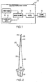
  • FIG. 2 is a perspective view of a turbine blade such as may be processed in accordance with an embodiment of the present invention.
  • FIG. 3 is a perspective view of a part of a turbine rotor assembly including turbine blades as may be processed according to an embodiment of the invention.
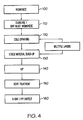
  • FIG. 4 is an exemplary functional block diagram of a coating process using the cold gas dynamic spray deposition of MCrAIYX powder as a coating on an HPT turbine blade.
  • Reference will now be made in detail to exemplary embodiments of the invention, examples of which are illustrated in the accompanying drawings. Wherever possible, the same reference numbers will be used throughout the drawings to refer to the same or like parts.
  • It has now been discovered that a modified MCrAlY, different from convention formulations, offers improved performance characteristics. The modified MCrAlY formulation includes the addition of other elements. Thus, the modified composition is represented by the designation MCrAIYX where X represents the additional constituent not present in conventional formulations.
  • In a preferred embodiment MCrAIYX represents the formula of the coating material. M is preferably selected from Ni, Co and Fe and/or alloys thereof. Cr is chromium; Al is aluminum, and Y is yttrium. X represents one or more of the following elements: Pt (Platinum), Hf (Hafnium), Si (Silicon), Zr (Zirconium), Ta (Tantalum), Re (Rhenium), Ru (Ruthenium), B (Boron), and C (Carbon). Further X may represent combinations of the designated elements. The composition may also include incidental impurities resulting from typical manufacturing processes. In a preferred embodiment two, three, or four components selected from the group represented by X are included in the modified formulation.
  • In the modified MCrAIYX formulation the constituents represented by X may provide a function of improving the environmental resistance of the alloy. Thus, the modified MCrAIYX demonstrates improved corrosion and oxidation resistance, especially at high temperatures.
  • In one embodiment, the MCrAlYX composition includes the following ranges for percentage by weight of each constituent.
    Element Range Weight %
    Co about 0 - about 35
    Cr about 10 - about 25
    Fe about 0 - about 35
    Al about 6 - about 20
    Pt about 0 - about 35
    Hf about 1.0 - about 5.0
    Si about 1.0 - about 6.0
    Nb about 0 - about 15
    Zr about 0 - about 5.0
    Ta about 0 - about 5.0
    Re about 0 - about 5.0
    Ru about 0 - about 5.0
    B about 0 - about 1.0
    C about 0 - about 0.2
    Y about 0.1- about 0.7
    Ni Remainder.
  • In a further preferred embodiment, the MCrAlYX composition described above excludes Platinum. Platinum is an expensive constituent, and it is desirable to provide a formulation that achieves a comparable performance without the use of expensive elements.
  • In a further preferred composition, the MCrAIYX includes one or more of the elements represented by X. Other embodiments include two or more, three or more, and four or more of the elements represented by X. In the further preferred embodiments of the MCrAIYX composition with less than all the elements represented by X included in the composition, the weight percentage of X in the total composition may fall between about 0 and about 28 per cent. Alternatively, the weight percentage of X in the total formulation may fall between about 0.5 and about 15 per cent. Alternatively and preferably, the weight percentage of X in the total formulation may fall between about 1.0 and about 7.0 per cent.
  • A preferred specific formulation of the MCrAlYX composition is as follows:
    Element Weight %
    Co about 20
    Cr about 25
    Al about 13
    Y about 0.3
    Hf about 2.0
    Si about 0.65
    Nb about 0.5
    Re about 3.0
    B about 0.1
    C about 0.1
    Ni Remainder.
  • A further preferred specific formulation of the MCrAIYX composition is as follows:
    Element Weight %
    Co about 20
    Cr about 22
    Al about 13
    Y about 0.3
    Hf about 2.0
    Si about 0.65
    Re about 3.0
    Ru about 1.5
    Nb about 0.5
    B about 0.1
    C about 0.1
    Ni Remainder.
  • An additional preferred specific formulation of the MCrAIYX composition is as follows:
    Element Weight %
    Co about 20
    Cr about 25
    Al about 13
    Y about 0.4
    Hf about 2.0
    Si about 0.80
    Nb about 0.5
    B about 0.1
    C about 0.1
    Ni Remainder.
  • The MCrAlYX composition is particularly intended for use as a coating on turbine blade surfaces. As such it is particularly adapted for use with turbine blades made of advanced superalloys. Thus some specific turbine substrates for which the composition is adapted for use include the following superalloys: IN-738, IN-792, MarM 247, C 101, Rene 80, Rene 125, Rene 142, GTD 111, Rene N5, CMSX 4, SC 180, PWA 1480, and PWA 1484.
  • The MCrAlYX composition described herein can be manufactured as a powder for use in depositions using a cold gas dynamic spraying technique. In one embodiment, an alloy including all elemental constituents is first prepared. The alloy material may be put in powderized form by conventional powder processing methods, such as inert gas atomization from ingots. Alternatively, non-alloyed powder blends may be prepared by mixing separate powders of individual elements or alloys. In a final powder composition prepared in this manner the weight percentage of each elemental constituent corresponds to the ranges earlier provided. A preferred diameter for the metallic powder particles, regardless how formed, is between about 5 to about 50 microns.
  • The MCrAlYX compositions described above demonstrate improved performance with respect to oxidation resistance and corrosion resistance. Turbine blade tips coated with such materials are better able to withstand the corrosive and oxidative forces encountered in a gas turbine engine.
  • In a preferred method, the MCrAIYX composition is deposited on a turbine blade as a coating through a cold gas dynamic spraying process. Referring now to FIG. 1 there is shown an exemplary cold gas dynamic spray system 10 illustrated diagrammatically. The system 10 is illustrated as a general scheme, and additional features and components can be implemented into the system 10 as necessary. The main components of the cold gas dynamic spray system 10 includes a powder feeder 11 for providing repair powder materials, a carrier gas supply 12 (typically including a heater), a mixing chamber 13 and a convergent-divergent nozzle 14. In general, the system 10 mixes the repair particles with a suitable pressurized gas in the mixing chamber 13. The particles are accelerated through the specially designed nozzle 14 and directed toward a target surface on the turbine component 15. When the particles strike the target surface, converted kinetic energy causes plastic deformation of the particles, which in turn causes the particle to form a bond with the target surface. Thus, the cold gas dynamic spray system 10 can bond powder materials to a gas turbine engine component surface.
  • The cold gas dynamic spray process is referred to as a "cold gas" process because the particles are mixed and applied at a temperature that is far below the melting point of the particles. The kinetic energy of the particles on impact with the target surface, rather than particle temperature, causes the particles to plastically deform and bond with the target surface. Therefore, bonding to the component surface takes place as a solid state process with insufficient thermal energy to transition the solid powders to molten droplets.
  • According to the present invention, the cold gas-dynamic spray system 10 applies metallic powdered materials that may be difficult to weld or otherwise apply to component surfaces. For example, welding processes involving superalloy substrates are conventionally performed in a well-shielded atmosphere such as an inert gas chamber or a chamber that is under vacuum. Maintaining such a controlled environment is inefficient in terms of both time and expense. In contrast, the cold gas-dynamic spray system 10 can be operated at ambient temperature and pressure environments.
  • While the method of applying modified MCrAlY powders may be applied to a variety of gas turbine engine components, it is well-suited to coating high pressure turbine blades. A typical turbine blade 20 is illustrated in FIG. 2. Turbine blade geometry and dimension have been designed differently, depending on turbine engine model and its application. For aero engines, such a blade is typically several inches in length. A turbine blade includes a serrated base assembly 21 , also called a mounting dovetail, tang, or christmas tree. Airfoil 22, a cuplike structure, includes a concave face 23 and a convex face 24. In the literature of turbine technology airfoil 22 may also be referred to as a bucket. Turbine blade 20 also includes leading edge 27 and trailing edge 28 which represent the edges of airfoil 22 that firstly and lastly encounter an air stream passing around airfoil 22. Turbine blade 20 also include tip 25. Tip 25 may include raised features known as "squealers" (not shown) in the industry. Turbine blade 20 is often composed of a highly durable material such as a superalloy. It is also desirable to cast turbine blades in a single crystal superalloy in order to maximize elevated-temperature properties and dimensional stability.
  • Referring now to FIG. 3 turbine blade 20 is affixed to a hub 26 at base assembly 21. Airfoil 22 extends radially outwardly from hub 26 toward shroud 29. In a jet engine assembly multiple such turbine blades are positioned in adjacent circumferential position along hub 26. Many gas turbine engines have a shroud structure 29. Shroud 29 surrounds a row of turbine blades at the upper (outer radial) end of turbine blade 20. Further shroud 29 includes groovel9. Turbine blades 20 are disposed so that tip 25 is within the area defined by groove 19. In operation, gases impinge on concave face 23 of airfoil 22 thereby providing the driving force for the turbine engine. Further the close fit of blade tip 25 within groove 19 minimizes the escape of gases around the turbine stage, thus increasing engine efficiency. The passage of hot gases through the gap between tip 25 and groove 19 leads to high temperature and pressure conditions at tip 25. Thus blade tips 25 may be coated with a hardened or protective layer to resist mechanical wear as well as corrosion and oxidation.
  • Examples of other components which may be treated with a modified MCrAlY coating include compressor blades, blisks or integrally bladed rotors (IBRs) and impellers or centrifugal compressors, which have blades that are integral to the rotor hub, nozzles, ducts, shrouds, shroud supports, and vanes.
  • Having described the MCrAIYX composition and cold gas dynamic spraying apparatus from a structural standpoint, a method of using such an assembly in a coating deposition with MCrAIYX will now be described.
  • Referring now to FIG. 4, there is shown a functional block diagram of the steps in one embodiment of the cold gas dynamic spraying process. This method includes the cold gas dynamic spray process, and also includes additional optional processes to optimize the resulting repairs. Cold gas dynamic spray involves "solid state" processes to effect bonding and coating build-up, and does not rely on the application of external thermal energy for bonding to occur. However, thermal energy may be provided after bonding has occurred since thermal energy promotes formation of the desired microstructure and phase distribution for the repaired components. Also, additional processing may be necessary to optimize bonding within the material and many thermo-mechanical properties for the material such as the elastic/plastic properties, mechanical properties, thermal conductivity and thermal expansion properties. In the method additional optional processing includes hot isostatic pressing and additional thermal treatments to consolidate and homogenize the cold gas-dynamic spray applied material and to restore metallurgical integrity to the repaired component.
  • A suitable workpiece is first identified in step 100. Inspection of the workpiece confirms that the workpiece is a suitable candidate for operation by a cold spray process. The workpiece should not suffer from mechanical defects or other damage that would disqualify it from service, after receiving the coating treatment.
  • Step 110 reflects that the workpiece may be subjected to a preprocessing treatment to prepare the piece for welding. In one embodiment a surface of the component/workpiece receives a pre-treatment machining and degreasing in order to remove materials that interfere with cold spraying such as corrosion, impurity buildups, and contamination on the face of the workpiece. In addition the piece may receive a grit blasting with an abrasive such as aluminum oxide.
  • After these preparatory steps, deposition of coating material commences in step 120 through cold gas spraying. In cold gas dynamic spraying, particles at a temperature below their melting temperature are accelerated and directed to a target surface on the turbine component. When the particles strike the target surface, the kinetic energy of the particles is converted into plastic deformation of the particle, causing the particle to form a strong bond with the target surface. The spraying step can include the application of coating material to a variety of different components in a gas turbine engine. For example, material can be applied to surfaces on compressor blades, turbine blades, impellers, and vanes in general, and to airfoil surfaces such as tips, knife seals, leading/trailing edges, and platforms.
  • The deposition of a coating layer through cold gas spraying may occur over several deposition cycles. A first pass takes place 120. After a first pass, the coating thickness of the first layer is checked, step 130. If the build-up of material is below that desired, a second pass occurs, a repeat of step 120, on top of the first layer. The thickness of material deposited is then checked again, step 130. In this manner a series of material deposition steps are repeated, if necessary, through repetitions of steps 120 and 130. Thus a series of spraying passes can build up a desired thickness of newly deposited MCrAIYX. A preferred thickness is up to 0.050 inch. Likewise, a series of spraying passes may be required in order to cover a desired surface area with subsequent spraying passes depositing material adjacent to coatings from earlier spraying passes.
  • Post spraying steps may also include procedures such as heat treatment. One preferred treatment is hot isostatic pressing (HIP) step 140. HIP is a high temperature, high-pressure process. The HIP process can be performed at a desired temperature that is sufficient to fully consolidate the cold-sprayed buildup and eliminate defects such as porosity. Additionally, the HIP process strengthens bonding between the coating material buildup and the underlying component, homogenizes the applied materials, and rejuvenates microstructures in the base material. Overall mechanical properties such as tensile and stress rupture strengths of repaired gas turbine components can thus be dramatically improved with the HIP process.
  • As one example of HIP parameters, pressing can be performed for 2 to 4 hours at temperatures of between about 1650 and about 1750 °F and at pressures of about 10 to about 15 ksi for most superalloys, although the procedure is carried out at up to about 30 ksi for some high-temperature alloys. Of course, this is just one example of the type of hot isostatic pressing process that can be used to remove defects after the application of repair materials.
  • In some embodiments, it may be desirable to perform a rapid cool following the HIP process to reduce the high-temperature solution heat treatment aftermath that could otherwise exist. One advantage of the rapid cool capability is that the component alloy and the coating material are retained in "solution treated condition," reducing the need for another solution treatment operation. In other words, the HIP followed by rapid cool can provide a combination of densification, homogenization and solution treat operation. Using this technique can thus eliminate the need for other heat treatment operations.
  • The next step 150 comprises performing an optional heat treatment on the coated component. The heat treatment can provide a full restoration of the mechanical properties of turbine components. It should be noted that in some applications it may be desirable to delete the high temperature solution treatment if such operation can be accomplished in step 140. However, some examples of heat treatments are described below for applications in which such a treatment is desired or necessary.
  • A two-stage heat treatment useful for components with superalloy substrates is applied in a first example. According to this example, a coated component is heated for about one hour at a temperature between about 1725 and about 1775 °F. After cooling the component with water, the component is heated between about two and about eight hours at a temperature between about 900 and about 1100 °F.
  • Another two-stage heat treatment is applied in a second example. According to this second example, a compressor blade or other component is heated for about one hour at a temperature between about 1550 and about 1650 °F. The component is air cooled, and then heated between about four and about eight hours at a temperature between about 1075 and about 1125 °F.
  • According to a third example, a component is heated for about one hour at a temperature between about 1800 and about 1850 °F. The component is then cooled with water or oil. The component is then heated between about four and about eight hours at a temperature between about 1050 and about 1100 °F.
  • Finally, an FPI (Fluorescent Penetration Inspection) inspection of a component such as a turbine blade, as well as an x-ray inspection, step 160, may follow. At this time the component may be returned to service, or placed in service for the first time.
  • A particular embodiment of the method to deposit the MCrAlYX composition is described as follows. As above-mentioned it is often the case that several deposition layers are required in order to build up an overall desired coating thickness of the MCrAlYX material. While MCrAIYX compositions which include Pt are desirable, it becomes expensive to deposit an entire coating, with multiple layers, made of a Pt-including MCrAIYX composition. It has thus been discovered that improved corrosion and oxidation resistance can be achieved where only certain deposition layers comprise the Pt-including MCrAlYX composition and the remaining deposition layers comprise the MCrAlYX composition without Pt, that is Pt-free MCrAIYX. Thus, for example, in a three layer deposition, the first layer may be composed of a Pt-free MCrAlYX, the second layer a Pt-including MCrAlYX, and the third layer a Pt-free MCrAlYX. Various combinations are thus possible, so long as some layers of the overall coating include Pt and others do not.
  • A variety of different systems and implementations can be used to perform the cold gas dynamic spraying process. For example, U.S. Patent No 5,302,414, entitled "Gas dynamic Spraying Method for Applying a Coating" and incorporated herein by reference, describes an apparatus designed to accelerate materials having a particle size diameter of between 5 to about 50 microns, and to mix the particles with a process gas to provide the particles with a density of mass flow between 0.05 and 17 g/s-cm2. Supersonic velocity is imparted to the gas flow, with the jet formed at high density and low temperature using a predetermined profile. The resulting gas and powder mixture is introduced into the supersonic jet to impart sufficient acceleration to ensure a particle velocity ranging between 300 and 1200 m/s. In this method, the particles are applied and deposited in the solid state, i.e., at a temperature which is considerably lower than the melting point of the powder material. The resulting coating is formed by the impact and kinetic energy of the particles which gets converted to high-speed plastic deformation, causing the particles to bond to the surface. The system typically uses gas pressures of between 5 and 20 atm, and at a temperature of up to 800 °F. As non limiting examples, the gases can comprise air, nitrogen, helium and mixtures thereof. Again, this system is but one example of the type of system that can be adapted to cold spray powder materials to the target surface.
  • The present invention thus provides an improved method for coating turbine engine components. The method utilizes a cold gas dynamic spray technique to coat turbine blades, compressor blades, impellers, blisks, and other turbine engine components. These methods can be used to coat a variety of surfaces thereon, thus improving the overall durability, reliability and performance of the turbine engine itself.
  • While the invention has been described with reference to a preferred embodiment, it will be understood by those skilled in the art that various changes may be made and equivalents may be substituted for elements thereof without departing from the scope of the invention. In addition, many modifications may be made to adapt to a particular situation or material to the teachings of the invention without departing from the essential scope thereof. Therefore, it is intended that the invention not be limited to the particular embodiment disclosed as the best mode contemplated for carrying out this invention, but that the invention will include all embodiments falling within the scope of the appended claims.

Claims (10)

  1. A method for applying a coating to a surface of a gas turbine engine component comprising:
    directing to the surface a metallic powder having the composition in weight percentages of Element Range Weight % Co about 0 - about 35 Cr about 10 - about 25 Fe about 0 - about 35 Al about 6 - about 20 Pt about 0 - about 35 Hf about 1.0 - about 5.0 Si about 1.0 - about 6.0 Nb about 0 - about 15 Zr about 0 - about 5.0 Ta about 0 - about 5.0 Re about 0 - about 5.0 Ru about 0 - about 5.0 B about 0 - about 1.0 C about 0 - about 0.2 Y about 0.1- about 0.7 Ni Remainder;
    wherein the weight percentage of Pt, Hf, Si, Nb, Zr, Ta, Re, Ru, B, and C to the total composition is within the range of about 0.1% to about 28.0%, and
    bonding the powder composition to the surface as a coating through cold gas dynamic spray technique 120.
  2. The method according to claim 1 wherein the weight percentage of Pt, Hf, Si, Nb, Zr, Ta, Re, Ru, B, and C to the total composition is within the range of about 0.5% to about 15.0%.
  3. The method according to claim 1 wherein the weight percentage of Pt, Hf, Si, Nb, Zr, Ta, Re, Ru, B, and C to the total composition is within the range of about 1.0% to about 7.0%.
  4. A method for preparing a coated high pressure turbine blade for assembly in a gas turbine engine comprising the steps of:
    providing a suitable turbine blade having a surface to be coated;
    preparing the turbine blade surface for cold gas dynamic spraying (110);
    depositing a coating layer on the turbine blade surface by cold gas dynamic spraying (120) a metallic powder composition wherein the powder composition comprises Element Range Weight % Co about 0 - about 35 Cr about 10 - about 25 Fe about 0 - about 35 Al about 6 - about 20 Pt about 0 - about 35 Hf about 1.0 - about 5.0 Si about 1.0 - about 6.0 Nb about 0 - about 15 Zr about 0 - about 5.0 Ta about 0 - about 5.0 Re about 0 - about 5.0 Ru about 0 - about 5.0 B about 0 - about 1.0 C about 0 - about 0.2 Y about 0.1- about 0.7 Ni remainder;
    checking the depth of the layer deposited (130);
    repeating the steps of depositing and checking the depth until a desired coating thickness is achieved; and
    heat treating the turbine blade (150).
  5. The method according to claim 4 wherein the step of heat treating the turbine blade comprises a hot isostatic pressing (140) of heating the turbine blade for approximately 2 to 4 hours at temperatures of between about 1650 and about 1750 °F and at pressures of about 10 to about 15 ksi.
  6. The method according to claim 4 wherein the step of heat treating comprises:
    heating the turbine blade for about one hour at a temperature between about 1725 and about 1775 °F;
    cooling the turbine blade, and
    heating the turbine blade between about two and about eight hours at a temperature between about 900 and about 1100 °F.
  7. The method according to claim 4 wherein the step of depositing a coating layer on the turbine blade surface by cold gas dynamic spraying further comprises:
    providing a powder particle size with diameter of between 5 to about 50 microns;
    mixing the particles with a process gas to provide a density of mass flow between 0.05 and 17 g/s-cm2; and
    accelerating the particles to a velocity ranging between 300 and 1200 m/s.
  8. The method according to claim 4 further comprising the steps of:
    depositing a first layer of Pt-including powder onto the surface; and
    depositing a second layer of Pt-free powder on top of the first layer.
  9. The method according to claim 4 wherein the step of preparing the turbine blade surface comprises at least one of the operations selected from the group consisting of degreasing, grinding, and grit blasting (110).
  10. A coated turbine blade comprising:
    an airfoil (22) having a convex face (24) and a concave face(23);
    a base assembly (21) attached to said airfoil (22);
    a tip (25) at the outer radial end of the airfoil; and
    a coated region on the airfoil wherein the coated region comprises a coating with a composition comprising Element Range Weight % Co about 0 - about 35 Cr about 10 - about 25 Fe about 0 - about 35 A1 about 6 - about 20 Pt about 0 - about 35 Hf about 1.0 - about 5.0 Si about 1.0 - about 6.0 Nb about 0 - about 15 Zr about 0 - about 5.0 Ta about 0 - about 5.0 Re about 0 - about 5.0 Ru about 0 - about 5.0 B about 0 - about 1.0 C about 0 - about 0.2 Y about 0.1 - about 0.7 Ni remainder.
EP05257658A 2004-12-14 2005-12-14 A method for applying environmental-resistant mcraly coatings on gas turbine components Withdrawn EP1672175A1 (en)

Applications Claiming Priority (1)

Application Number Priority Date Filing Date Title
US11/013,218 US7378132B2 (en) 2004-12-14 2004-12-14 Method for applying environmental-resistant MCrAlY coatings on gas turbine components

Publications (1)

Publication Number Publication Date
EP1672175A1 true EP1672175A1 (en) 2006-06-21

Family

ID=35967059

Family Applications (1)

Application Number Title Priority Date Filing Date
EP05257658A Withdrawn EP1672175A1 (en) 2004-12-14 2005-12-14 A method for applying environmental-resistant mcraly coatings on gas turbine components

Country Status (2)

Country Link
US (1) US7378132B2 (en)
EP (1) EP1672175A1 (en)

Cited By (16)

* Cited by examiner, † Cited by third party
Publication number Priority date Publication date Assignee Title
EP1921181A1 (en) * 2006-10-27 2008-05-14 United Technologies Corporation Cold sprayed porous metal seals
WO2008140588A1 (en) * 2006-11-30 2008-11-20 Honeywell International Inc. Method for producing an environmentally-resistant thermal barrier coating system on a component
WO2009065385A1 (en) * 2007-11-23 2009-05-28 Mtu Aero Engines Gmbh Method for repairing a gas turbine component
EP2158338A2 (en) * 2007-06-27 2010-03-03 United Technologies Corporation Metallic alloy composition and protective coating
DE102008057159A1 (en) * 2008-11-13 2010-05-20 Mtu Aero Engines Gmbh Gas turbine useful in aircraft engine, comprises two rotor discs, which are braced to each other and which directly adjoin to each other in a contact area, where one of the rotor discs is equipped in the contact area
DE102009036407A1 (en) * 2009-08-06 2011-02-10 Mtu Aero Engines Gmbh Abradable blade tip pad
CN102888583A (en) * 2012-10-29 2013-01-23 中国科学院上海硅酸盐研究所 CoNiCrAlY coating and production process and application thereof
CN104313567A (en) * 2014-09-12 2015-01-28 湖州鑫隆镀膜科技有限公司 Metal chromium production technology for replacing electroplating technology
US8961867B2 (en) 2008-09-09 2015-02-24 H.C. Starck Inc. Dynamic dehydriding of refractory metal powders
US9095932B2 (en) 2006-12-13 2015-08-04 H.C. Starck Inc. Methods of joining metallic protective layers
US9108273B2 (en) 2011-09-29 2015-08-18 H.C. Starck Inc. Methods of manufacturing large-area sputtering targets using interlocking joints
EP3096908A4 (en) * 2014-01-24 2017-03-01 United Technologies Corporation Conditioning one or more additive manufactured objects
US9783882B2 (en) 2007-05-04 2017-10-10 H.C. Starck Inc. Fine grained, non banded, refractory metal sputtering targets with a uniformly random crystallographic orientation, method for making such film, and thin film based devices and products made therefrom
WO2017220996A1 (en) * 2016-06-20 2017-12-28 The Welding Institute Method of coating or repairing substrates
EP3314037A4 (en) * 2015-06-29 2019-01-30 Oerlikon Metco (US) Inc. Cold gas spray coating methods and compositions
EP4279633A1 (en) * 2022-05-18 2023-11-22 Rolls-Royce plc Method for improving corrosion and fatigue crack resistance

Families Citing this family (26)

* Cited by examiner, † Cited by third party
Publication number Priority date Publication date Assignee Title
JP4607530B2 (en) * 2004-09-28 2011-01-05 株式会社日立製作所 Heat resistant member having a thermal barrier coating and gas turbine
US20060222776A1 (en) * 2005-03-29 2006-10-05 Honeywell International, Inc. Environment-resistant platinum aluminide coatings, and methods of applying the same onto turbine components
US20070098913A1 (en) * 2005-10-27 2007-05-03 Honeywell International, Inc. Method for coating turbine engine components with metal alloys using high velocity mixed elemental metals
CH699312A1 (en) * 2008-08-15 2010-02-15 Alstom Technology Ltd Blade arrangement for a gas turbine.
US8268237B2 (en) * 2009-01-08 2012-09-18 General Electric Company Method of coating with cryo-milled nano-grained particles
DE102009039824B4 (en) * 2009-09-02 2014-10-16 Siemens Aktiengesellschaft Rotor shaft for a steam turbine
US20110129351A1 (en) * 2009-11-30 2011-06-02 Nripendra Nath Das Near net shape composite airfoil leading edge protective strips made using cold spray deposition
US8708659B2 (en) 2010-09-24 2014-04-29 United Technologies Corporation Turbine engine component having protective coating
US10227678B2 (en) 2011-06-09 2019-03-12 General Electric Company Cobalt-nickel base alloy and method of making an article therefrom
US8544769B2 (en) 2011-07-26 2013-10-01 General Electric Company Multi-nozzle spray gun
RU2476616C1 (en) * 2011-11-18 2013-02-27 Российская Федерация, от имени которой выступает Министерство промышленности и торговли Российской Федерации (Минпромторг России) Wear-resistant alloy on basis of nickel for application of wear and corrosion resistant coatings to structural elements with microplasma or supersonic gas-dynamic sputtering
US9033670B2 (en) * 2012-04-11 2015-05-19 Honeywell International Inc. Axially-split radial turbines and methods for the manufacture thereof
US9115586B2 (en) 2012-04-19 2015-08-25 Honeywell International Inc. Axially-split radial turbine
US9475119B2 (en) * 2012-08-03 2016-10-25 General Electric Company Molded articles
US8697250B1 (en) 2013-02-14 2014-04-15 Praxair S.T. Technology, Inc. Selective oxidation of a modified MCrAlY composition loaded with high levels of ceramic acting as a barrier to specific oxide formations
US9476305B2 (en) 2013-05-13 2016-10-25 Honeywell International Inc. Impingement-cooled turbine rotor
US9828658B2 (en) 2013-08-13 2017-11-28 Rolls-Royce Corporation Composite niobium-bearing superalloys
US9938610B2 (en) 2013-09-20 2018-04-10 Rolls-Royce Corporation High temperature niobium-bearing superalloys
EP3071732B1 (en) 2013-11-19 2019-11-13 United Technologies Corporation Article having variable composition coating
WO2015130528A1 (en) 2014-02-25 2015-09-03 Siemens Aktiengesellschaft Turbine component thermal barrier coating with crack isolating engineered surface features
US8939706B1 (en) 2014-02-25 2015-01-27 Siemens Energy, Inc. Turbine abradable layer with progressive wear zone having a frangible or pixelated nib surface
WO2016133987A2 (en) 2015-02-18 2016-08-25 Siemens Aktiengesellschaft Forming cooling passages in combustion turbine superalloy castings
US9151175B2 (en) 2014-02-25 2015-10-06 Siemens Aktiengesellschaft Turbine abradable layer with progressive wear zone multi level ridge arrays
US9243511B2 (en) 2014-02-25 2016-01-26 Siemens Aktiengesellschaft Turbine abradable layer with zig zag groove pattern
WO2016133583A1 (en) 2015-02-18 2016-08-25 Siemens Aktiengesellschaft Turbine shroud with abradable layer having ridges with holes
US11426822B2 (en) * 2020-12-03 2022-08-30 General Electric Company Braze composition and process of using

Citations (15)

* Cited by examiner, † Cited by third party
Publication number Priority date Publication date Assignee Title
US3676085A (en) 1971-02-18 1972-07-11 United Aircraft Corp Cobalt base coating for the superalloys
US4246323A (en) 1977-07-13 1981-01-20 United Technologies Corporation Plasma sprayed MCrAlY coating
US4532191A (en) 1982-09-22 1985-07-30 Exxon Research And Engineering Co. MCrAlY cladding layers and method for making same
US5302414A (en) 1990-05-19 1994-04-12 Anatoly Nikiforovich Papyrin Gas-dynamic spraying method for applying a coating
EP0688886A1 (en) * 1994-06-24 1995-12-27 Praxair S.T. Technology, Inc. A process for producing carbide particles dispersed in a MCrAIY-based coating
US5732467A (en) * 1996-11-14 1998-03-31 General Electric Company Method of repairing directionally solidified and single crystal alloy parts
US20020066770A1 (en) * 2000-12-05 2002-06-06 Siemens Westinghouse Power Corporation Cold spray repair process
US6410159B1 (en) 1999-10-29 2002-06-25 Praxair S. T. Technology, Inc. Self-bonding MCrAly powder
US20020102360A1 (en) * 2001-01-30 2002-08-01 Siemens Westinghouse Power Corporation Thermal barrier coating applied with cold spray technique
US20030126800A1 (en) * 2001-12-05 2003-07-10 Siemens Westinghouse Power Corporation Mixed powder deposition of components for wear, erosion and abrasion resistant applications
EP1382707A1 (en) * 2002-07-17 2004-01-21 Siemens Aktiengesellschaft Layer system
EP1398394A1 (en) * 2002-08-13 2004-03-17 Howmet Research Corporation Cold spraying method for MCrAIX coating
US20040126499A1 (en) * 2002-06-04 2004-07-01 Linde Aktiengesellschaft Process and device for cold gas spraying
US20040202885A1 (en) * 2001-08-01 2004-10-14 Seth Brij B. Component having wear coating applied by cold spray process
US6905728B1 (en) * 2004-03-22 2005-06-14 Honeywell International, Inc. Cold gas-dynamic spray repair on gas turbine engine components

Family Cites Families (39)

* Cited by examiner, † Cited by third party
Publication number Priority date Publication date Assignee Title
US3145287A (en) * 1961-07-14 1964-08-18 Metco Inc Plasma flame generator and spray gun
US3961098A (en) * 1973-04-23 1976-06-01 General Electric Company Coated article and method and material of coating
US3958097A (en) * 1974-05-30 1976-05-18 Metco, Inc. Plasma flame-spraying process employing supersonic gaseous streams
US4233335A (en) * 1979-03-06 1980-11-11 Etlin Vladimir N Electrostatic coating method
US4416421A (en) * 1980-10-09 1983-11-22 Browning Engineering Corporation Highly concentrated supersonic liquified material flame spray method and apparatus
US4518442A (en) * 1981-11-27 1985-05-21 United Technologies Corporation Method of producing columnar crystal superalloy material with controlled orientation and product
US4680199A (en) * 1986-03-21 1987-07-14 United Technologies Corporation Method for depositing a layer of abrasive material on a substrate
US5261940A (en) * 1986-12-23 1993-11-16 United Technologies Corporation Beta titanium alloy metal matrix composites
US4865252A (en) * 1988-05-11 1989-09-12 The Perkin-Elmer Corporation High velocity powder thermal spray gun and method
DE3918380A1 (en) * 1989-06-06 1990-12-20 Starck Hermann C Fa HIGH-TEMPERATURE COMPOSITE MATERIAL, METHOD FOR THE PRODUCTION AND USE THEREOF
US5059095A (en) * 1989-10-30 1991-10-22 The Perkin-Elmer Corporation Turbine rotor blade tip coated with alumina-zirconia ceramic
DE4015208C1 (en) 1990-05-11 1991-06-27 Mtu Muenchen Gmbh
US5071059A (en) * 1991-03-11 1991-12-10 General Motors Corporation Method for joining single crystal turbine blade halves
US5268045A (en) * 1992-05-29 1993-12-07 John F. Wolpert Method for providing metallurgically bonded thermally sprayed coatings
TW493016B (en) * 1994-06-24 2002-07-01 Praxair Technology Inc A process for producing an oxide dispersed MCrAly-based coating
US5795626A (en) * 1995-04-28 1998-08-18 Innovative Technology Inc. Coating or ablation applicator with a debris recovery attachment
DE19545025A1 (en) * 1995-12-02 1997-06-05 Abb Research Ltd Method for applying a metallic adhesive layer for ceramic thermal insulation layers on metallic components
US6366727B1 (en) * 1996-11-07 2002-04-02 3M Innovative Properties Company Light-illuminating rods
JP3302589B2 (en) * 1997-02-06 2002-07-15 株式会社日立製作所 Ceramic coated gas turbine blade
US5954275A (en) * 1997-04-02 1999-09-21 Toyota Jidosha Kabushiki Kaisha Rotary atomizing electrostatic coating apparatus
CA2211961C (en) * 1997-07-29 2001-02-27 Pyrogenesis Inc. Near net-shape vps formed multilayered combustion system components and method of forming the same
US6136453A (en) 1998-11-24 2000-10-24 General Electric Company Roughened bond coat for a thermal barrier coating system and method for producing
US6120832A (en) * 1998-11-25 2000-09-19 The Lubrizol Corporation Method and apparatus for measuring the transfer efficiency of a coating material
US20020005233A1 (en) * 1998-12-23 2002-01-17 John J. Schirra Die cast nickel base superalloy articles
KR100364656B1 (en) * 2000-06-22 2002-12-16 삼성전자 주식회사 Chemical Vapor Deposition Method for depositing silicide and Apparatus for performing the same
US6602545B1 (en) * 2000-07-25 2003-08-05 Ford Global Technologies, L.L.C. Method of directly making rapid prototype tooling having free-form shape
US6475642B1 (en) * 2000-08-31 2002-11-05 General Electric Company Oxidation-resistant coatings, and related articles and processes
US6434876B1 (en) * 2000-09-26 2002-08-20 General Electric Company Method of applying a particle-embedded coating to a substrate
US6365222B1 (en) * 2000-10-27 2002-04-02 Siemens Westinghouse Power Corporation Abradable coating applied with cold spray technique
CN1205357C (en) * 2001-05-31 2005-06-08 三菱重工业株式会社 Coating forming method and coating forming material and abrasive coating forming sheet
US6592947B1 (en) * 2002-04-12 2003-07-15 Ford Global Technologies, Llc Method for selective control of corrosion using kinetic spraying
CN100430499C (en) * 2002-08-16 2008-11-05 阿尔斯托姆科技有限公司 Intermetallic material and use of said material
US6808339B2 (en) * 2002-08-23 2004-10-26 State Of California Department Of Transportation Plantable geosynthetic reinforced retaining wall
EP1411210A1 (en) * 2002-10-15 2004-04-21 ALSTOM Technology Ltd Method of depositing an oxidation and fatigue resistant MCrAIY-coating
US20040082069A1 (en) * 2002-10-25 2004-04-29 Liang Jiang Systems and methods for estimating exposure temperatures and remaining operational life of high temperature components
US20040086635A1 (en) * 2002-10-30 2004-05-06 Grossklaus Warren Davis Method of repairing a stationary shroud of a gas turbine engine using laser cladding
US6838191B1 (en) * 2003-05-20 2005-01-04 The United States Of America As Represented By The Admistrator Of The National Aeronautics And Space Administration Blanch resistant and thermal barrier NiAl coating systems for advanced copper alloys
US20050220995A1 (en) * 2004-04-06 2005-10-06 Yiping Hu Cold gas-dynamic spraying of wear resistant alloys on turbine blades
US20060045785A1 (en) * 2004-08-30 2006-03-02 Yiping Hu Method for repairing titanium alloy components

Patent Citations (16)

* Cited by examiner, † Cited by third party
Publication number Priority date Publication date Assignee Title
US3676085A (en) 1971-02-18 1972-07-11 United Aircraft Corp Cobalt base coating for the superalloys
US4246323A (en) 1977-07-13 1981-01-20 United Technologies Corporation Plasma sprayed MCrAlY coating
US4532191A (en) 1982-09-22 1985-07-30 Exxon Research And Engineering Co. MCrAlY cladding layers and method for making same
US5302414A (en) 1990-05-19 1994-04-12 Anatoly Nikiforovich Papyrin Gas-dynamic spraying method for applying a coating
US5302414B1 (en) 1990-05-19 1997-02-25 Anatoly N Papyrin Gas-dynamic spraying method for applying a coating
EP0688886A1 (en) * 1994-06-24 1995-12-27 Praxair S.T. Technology, Inc. A process for producing carbide particles dispersed in a MCrAIY-based coating
US5732467A (en) * 1996-11-14 1998-03-31 General Electric Company Method of repairing directionally solidified and single crystal alloy parts
US6410159B1 (en) 1999-10-29 2002-06-25 Praxair S. T. Technology, Inc. Self-bonding MCrAly powder
US20020066770A1 (en) * 2000-12-05 2002-06-06 Siemens Westinghouse Power Corporation Cold spray repair process
US20020102360A1 (en) * 2001-01-30 2002-08-01 Siemens Westinghouse Power Corporation Thermal barrier coating applied with cold spray technique
US20040202885A1 (en) * 2001-08-01 2004-10-14 Seth Brij B. Component having wear coating applied by cold spray process
US20030126800A1 (en) * 2001-12-05 2003-07-10 Siemens Westinghouse Power Corporation Mixed powder deposition of components for wear, erosion and abrasion resistant applications
US20040126499A1 (en) * 2002-06-04 2004-07-01 Linde Aktiengesellschaft Process and device for cold gas spraying
EP1382707A1 (en) * 2002-07-17 2004-01-21 Siemens Aktiengesellschaft Layer system
EP1398394A1 (en) * 2002-08-13 2004-03-17 Howmet Research Corporation Cold spraying method for MCrAIX coating
US6905728B1 (en) * 2004-03-22 2005-06-14 Honeywell International, Inc. Cold gas-dynamic spray repair on gas turbine engine components

Cited By (23)

* Cited by examiner, † Cited by third party
Publication number Priority date Publication date Assignee Title
US8192792B2 (en) 2006-10-27 2012-06-05 United Technologies Corporation Cold sprayed porous metal seals
EP1921181A1 (en) * 2006-10-27 2008-05-14 United Technologies Corporation Cold sprayed porous metal seals
WO2008140588A1 (en) * 2006-11-30 2008-11-20 Honeywell International Inc. Method for producing an environmentally-resistant thermal barrier coating system on a component
US9095932B2 (en) 2006-12-13 2015-08-04 H.C. Starck Inc. Methods of joining metallic protective layers
US9783882B2 (en) 2007-05-04 2017-10-10 H.C. Starck Inc. Fine grained, non banded, refractory metal sputtering targets with a uniformly random crystallographic orientation, method for making such film, and thin film based devices and products made therefrom
EP2158338A2 (en) * 2007-06-27 2010-03-03 United Technologies Corporation Metallic alloy composition and protective coating
EP2158338A4 (en) * 2007-06-27 2010-12-08 United Technologies Corp Metallic alloy composition and protective coating
WO2009065385A1 (en) * 2007-11-23 2009-05-28 Mtu Aero Engines Gmbh Method for repairing a gas turbine component
US8961867B2 (en) 2008-09-09 2015-02-24 H.C. Starck Inc. Dynamic dehydriding of refractory metal powders
DE102008057159A1 (en) * 2008-11-13 2010-05-20 Mtu Aero Engines Gmbh Gas turbine useful in aircraft engine, comprises two rotor discs, which are braced to each other and which directly adjoin to each other in a contact area, where one of the rotor discs is equipped in the contact area
US9260784B2 (en) 2009-08-06 2016-02-16 Mtu Aero Engines Gmbh Blade tip coating that can be rubbed off
DE102009036407A1 (en) * 2009-08-06 2011-02-10 Mtu Aero Engines Gmbh Abradable blade tip pad
US9108273B2 (en) 2011-09-29 2015-08-18 H.C. Starck Inc. Methods of manufacturing large-area sputtering targets using interlocking joints
US9120183B2 (en) 2011-09-29 2015-09-01 H.C. Starck Inc. Methods of manufacturing large-area sputtering targets
US9293306B2 (en) 2011-09-29 2016-03-22 H.C. Starck, Inc. Methods of manufacturing large-area sputtering targets using interlocking joints
US9412568B2 (en) 2011-09-29 2016-08-09 H.C. Starck, Inc. Large-area sputtering targets
CN102888583B (en) * 2012-10-29 2014-09-10 中国科学院上海硅酸盐研究所 CoNiCrAlY coating and production process and application thereof
CN102888583A (en) * 2012-10-29 2013-01-23 中国科学院上海硅酸盐研究所 CoNiCrAlY coating and production process and application thereof
EP3096908A4 (en) * 2014-01-24 2017-03-01 United Technologies Corporation Conditioning one or more additive manufactured objects
CN104313567A (en) * 2014-09-12 2015-01-28 湖州鑫隆镀膜科技有限公司 Metal chromium production technology for replacing electroplating technology
EP3314037A4 (en) * 2015-06-29 2019-01-30 Oerlikon Metco (US) Inc. Cold gas spray coating methods and compositions
WO2017220996A1 (en) * 2016-06-20 2017-12-28 The Welding Institute Method of coating or repairing substrates
EP4279633A1 (en) * 2022-05-18 2023-11-22 Rolls-Royce plc Method for improving corrosion and fatigue crack resistance

Also Published As

Publication number Publication date
US20080038575A1 (en) 2008-02-14
US7378132B2 (en) 2008-05-27

Similar Documents

Publication Publication Date Title
US7378132B2 (en) Method for applying environmental-resistant MCrAlY coatings on gas turbine components
US20060222776A1 (en) Environment-resistant platinum aluminide coatings, and methods of applying the same onto turbine components
EP1634976A1 (en) Method for applying abrasive and environment-resistant coatings onto turbine components
EP1730323B1 (en) Cold gas-dynamic spray repair on gas turbine engine components
US20060045785A1 (en) Method for repairing titanium alloy components
US20180347390A1 (en) Turbine Clearance Control Coatings and Method
US20060219330A1 (en) Nickel-based superalloy and methods for repairing gas turbine components
US20140301861A1 (en) Airfoil having an erosion-resistant coating thereon
EP3480428B1 (en) Abrasive airfoil tip and fabrication method thereof
US9200521B2 (en) Components with micro cooled coating layer and methods of manufacture
EP2444515A2 (en) Rough dense ceramic sealing surface in turbomachines
US20060219329A1 (en) Repair nickel-based superalloy and methods for refurbishment of gas turbine components
US9249672B2 (en) Components with cooling channels and methods of manufacture
WO2006075994A2 (en) Cold gas-dynamic spraying of wear resistant alloys on turbine blades
EP3239475B1 (en) Outer airseal abradable rub strip
US6532657B1 (en) Pre-service oxidation of gas turbine disks and seals
US20100008816A1 (en) Nickel-based superalloys, repaired turbine engine components, and methods for repairing turbine components
JP2013147746A (en) Coating, turbine component, and process of fabricating turbine component
US20130078418A1 (en) Components with cooling channels and methods of manufacture
US10053987B2 (en) Components with cooling channels and methods of manufacture
US8652650B2 (en) Platinum-modified nickel-based superalloys, methods of repairing turbine engine components, and turbine engine components
US20150369053A1 (en) Components with micro cooled patterned coating layer and methods of manufacture
JPH02230902A (en) Method for improving corrosion resistance and erosion resistance of vane for rotating heat engine and protection film
JP3281842B2 (en) Corrosion resistant surface treatment method for gas turbine blade and its moving and stationary blade
EP4328348A1 (en) Gas turbine engine component with copper oxide coating

Legal Events

Date Code Title Description
PUAI Public reference made under article 153(3) epc to a published international application that has entered the european phase

Free format text: ORIGINAL CODE: 0009012

AK Designated contracting states

Kind code of ref document: A1

Designated state(s): AT BE BG CH CY CZ DE DK EE ES FI FR GB GR HU IE IS IT LI LT LU LV MC NL PL PT RO SE SI SK TR

AX Request for extension of the european patent

Extension state: AL BA HR MK YU

17P Request for examination filed

Effective date: 20061212

17Q First examination report despatched

Effective date: 20070116

AKX Designation fees paid

Designated state(s): DE FR GB

STAA Information on the status of an ep patent application or granted ep patent

Free format text: STATUS: THE APPLICATION IS DEEMED TO BE WITHDRAWN

18D Application deemed to be withdrawn

Effective date: 20070530