EP1672120A1 - Composite doctor blade - Google Patents
Composite doctor blade Download PDFInfo
- Publication number
- EP1672120A1 EP1672120A1 EP05026142A EP05026142A EP1672120A1 EP 1672120 A1 EP1672120 A1 EP 1672120A1 EP 05026142 A EP05026142 A EP 05026142A EP 05026142 A EP05026142 A EP 05026142A EP 1672120 A1 EP1672120 A1 EP 1672120A1
- Authority
- EP
- European Patent Office
- Prior art keywords
- doctor blade
- blade
- doctor
- plane
- profiling
- Prior art date
- Legal status (The legal status is an assumption and is not a legal conclusion. Google has not performed a legal analysis and makes no representation as to the accuracy of the status listed.)
- Granted
Links
- 239000002131 composite material Substances 0.000 title claims abstract description 16
- 230000002787 reinforcement Effects 0.000 description 4
- 239000000835 fiber Substances 0.000 description 3
- 230000014759 maintenance of location Effects 0.000 description 3
- 238000004519 manufacturing process Methods 0.000 description 3
- 239000000463 material Substances 0.000 description 2
- 239000011159 matrix material Substances 0.000 description 2
- 239000002994 raw material Substances 0.000 description 2
- 229920000049 Carbon (fiber) Polymers 0.000 description 1
- 239000004593 Epoxy Substances 0.000 description 1
- 239000004952 Polyamide Substances 0.000 description 1
- 239000004962 Polyamide-imide Substances 0.000 description 1
- 230000015572 biosynthetic process Effects 0.000 description 1
- 239000004917 carbon fiber Substances 0.000 description 1
- 239000011248 coating agent Substances 0.000 description 1
- 238000000576 coating method Methods 0.000 description 1
- 230000000694 effects Effects 0.000 description 1
- 239000003365 glass fiber Substances 0.000 description 1
- 238000003754 machining Methods 0.000 description 1
- 238000000034 method Methods 0.000 description 1
- 239000000203 mixture Substances 0.000 description 1
- 239000004033 plastic Substances 0.000 description 1
- 229920003023 plastic Polymers 0.000 description 1
- 229920002647 polyamide Polymers 0.000 description 1
- 229920002312 polyamide-imide Polymers 0.000 description 1
- 229920000728 polyester Polymers 0.000 description 1
- 238000006748 scratching Methods 0.000 description 1
- 230000002393 scratching effect Effects 0.000 description 1
- 239000007787 solid Substances 0.000 description 1
- -1 vinylesterurethane Substances 0.000 description 1
- 238000004804 winding Methods 0.000 description 1
Images

Classifications
-
- D—TEXTILES; PAPER
- D21—PAPER-MAKING; PRODUCTION OF CELLULOSE
- D21G—CALENDERS; ACCESSORIES FOR PAPER-MAKING MACHINES
- D21G3/00—Doctors
- D21G3/005—Doctor knifes
-
- B—PERFORMING OPERATIONS; TRANSPORTING
- B05—SPRAYING OR ATOMISING IN GENERAL; APPLYING FLUENT MATERIALS TO SURFACES, IN GENERAL
- B05C—APPARATUS FOR APPLYING FLUENT MATERIALS TO SURFACES, IN GENERAL
- B05C11/00—Component parts, details or accessories not specifically provided for in groups B05C1/00 - B05C9/00
- B05C11/02—Apparatus for spreading or distributing liquids or other fluent materials already applied to a surface ; Controlling means therefor; Control of the thickness of a coating by spreading or distributing liquids or other fluent materials already applied to the coated surface
- B05C11/04—Apparatus for spreading or distributing liquids or other fluent materials already applied to a surface ; Controlling means therefor; Control of the thickness of a coating by spreading or distributing liquids or other fluent materials already applied to the coated surface with blades
- B05C11/044—Apparatus for spreading or distributing liquids or other fluent materials already applied to a surface ; Controlling means therefor; Control of the thickness of a coating by spreading or distributing liquids or other fluent materials already applied to the coated surface with blades characterised by means for holding the blades
Definitions
- the present invention concerns a composite doctor blade to be installed in a blade holder which contains a throat, and where the rear part of the doctor blade made of a composite material has a profiling which protrudes beyond the plane defined by the doctor blade in order to retain the doctor blade in the blade holder.
- U.S. Pat. No. 4241691 describes a composite doctor blade fitted in a blade holder.
- the said doctor blades are used for instance in the doctors of paper machines.
- the blade holder has a throat which matches the doctor blade and its profiling.
- the profiling which is thicker than the rest of the doctor blade, retains the doctor blade in the blade holder thus preventing the blade from falling out of the throat.
- the profiling also retains the doctor blade in the blade holder in the correct position and location.
- doctor blade described above is only suited for use in blade holders specifically designed for it. Hence, it cannot be applied universally. Moreover, the thick profiling makes the doctor blade unnecessarily rigid, which makes its use and handling more difficult.
- An objective of the present invention is to accomplish a composite doctor blade which can be used more universally and which is more user friendly than before and which avoids the drawbacks of prior art solutions.
- the characteristic features of the present invention will be more fully understood from the enclosed patent claims.
- the profiling is designed and dimensioned in a new and surprising way.
- the doctor blade can hence be fitted easily to various types of blade holders.
- the doctor blade is more durable than before.
- the doctor blade can also be made considerably more flexible than before so that especially the handling of the doctor blade is easier and safer than before.
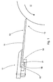
- FIG. 1 shows the doctor blade 10 according to the invention installed in the blade holder 11 of the doctor.
- the doctor blade according to the invention can be used, for instance, in coating equipment or in other similar devices.
- the surface of the roll 12 is doctored by the front part 13 of the doctor blade 10.
- the doctor blade 10 is installed in the blade holder 11 which is part of the doctor and which is presented only in part in FIG. 1.
- the rear part 14 of the doctor blade 10 made of a composite material has a profiling 16 which protrudes from the plane 18 defined by the doctor blade in order to retain the doctor blade 10 in the blade holder 11.
- the profiling 16 stays in the throat 15 of the blade holder 11 thus preventing the doctor blade 10 from falling out.
- part 17 of the profiling 16 protrudes from the plane 18 at one side only at a distance from the rear part 14.
- the part 17 is higher than its width in the cross-sectional plane of the doctor blade.
- the doctor blade can hence be used in ordinary blade holders.
- the profiling extends essentially over the entire length of the doctor blade and is of the same piece and material as the rest of the doctor blade.
- the doctor blade is hence of one piece without any falling or detaching parts.
- a doctor blade made exclusively of a composite material does not scratch the blade holder.
- the said part is higher than its width.
- the height of the part 17 from the plane 18 is 1.5 - 3, preferably 1.6 - 2.4 times the thickness of the doctor blade. This gives a sufficient retention effect at a preferably low consumption of raw material.
- the distance of the part 17 from the rear part 14 of the doctor blade 11 is less than three times the thickness of the doctor blade 11. The said dimensioning ensures the suitability of the doctor blade to as many types of blade holders as possible.
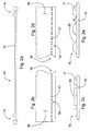
- FIG. 2a shows a doctor blade according to the invention during the manufacturing stage.
- a unified blank 22 is first formed preferably from a composite material.
- Composite material comprises reinforcement, for example glass or carbon fibers, and a matrix of plastic material, for example epoxy, polyester, vinylesterurethane, polyamide, polyamideimide.
- the application in FIG. 2a shows a single blank with two doctor blades which have profilings 16.
- the doctor blades are detached from the formed blank 22.
- the doctor blades detached are ready for use without machining and contain the retention members.
- the blank described is preferably formed by pultrusion. This method gives excellent shape and dimensional precision, eliminating the need to separately finish the doctor blade.
- the desired profiling is created by adjusting the settings of the pultrusion device and by using a suitable nozzle shape.
- Pultrusion also allows the orientation of the reinforcement fibers contained in the composite material.
- the reinforcement fibers can be arranged essentially in the lateral direction of the doctor blade. This makes the doctor blade rigid laterally but essentially flexible longitudinally.
- a doctor blade which is flexible longitudinally adapts well to the shapes of the surface being doctored.
- FIG. 3b indicates the longitudinal direction of the doctor blade with a solid arrow and the lateral direction with a broken arrow.
- pultrusion gives a blank with excellent shape and dimensional precision, so that in principle the doctor blades will be ready for use after being detached. It is also easy to install a doctor blade with excellent shape and dimension precision to the blade holder.
- the spherical part in the profiling is mostly of excess raw material and it is also removed during detaching. In practice, this part contains more matrix material than reinforcement fibers. Its composition is hence different from the rest of the doctor blade or from the protruding part which is essentially homogeneous with the doctor blade.
- the part according to the invention is thus durable and it acts in the same manner as the doctor blade. Doctor blade detachment can be easily integrated in the pultrusion device so that an endless doctor blade can be manufactured easily and quickly.
- a doctor blade 10 according to the invention is presented as a side view in FIG. 3a.
- a similar doctor blade 10 installed in a blade holder 11 is presented in FIG. 1. If the blade holder allows, the spherical part can be left as part of the doctor blade.
- the thickness of the doctor blade is 1.8 mm and its width is 90 mm.
- the points of removal of the spherical parts are indicated by the broken lines in the figure.
- the parts which protrude from the plane at the said points are at a distance of 6.7 mm from the rear part where a shear surface is thus formed.
- the said dimension is from the shear surface to the centre of the protruding part.
- the height of the left-hand side part from the plane is approx. 3 mm, and the height of the righthand side part from the plane is approx. 4 mm.
- the doctor blade according to the invention has a homogeneous structure.
- the doctor blade for instance, acts in a similar manner over its entire length when being loaded.
- the part according to the invention has a minor impact on the behavior of the doctor blade.
- the part 17 preferably has grooves 19 which cut the part 17 at regular intervals, with the grooves 19 situated in the lateral direction of the doctor blade. The said grooves improve the flexibility of the doctor blade essentially while the retention capacity is still sufficient. This also reduces the total weight of the doctor blade.
- the doctor blade can also be wound using a smaller radius whereby the handling of the doctor blade becomes safer. Moreover, flexibility is an advantage in conjunction with an automatic blade changing device.
- the formation of the groove can be integrated with the manufacturing process of the doctor blade, or the grooves can be machined afterwards. Even a small groove will increase flexibility easily. According to the invention, however, the groove 19 extends essentially up to the plane 18. Hence, the flexibility of the doctor blade almost corresponds to a fully smooth doctor blade. The ratio of the width of the groove to the size of the part also has an impact on flexibility. The flexibility of the doctor blade can be increased by widening and deepening the groove. According to the invention, the width of the groove 19 is 0.8 - 1.2 times the width of part 17 in the cross-sectional plane of the doctor blade.
- the walls 20 of part 17 which restrict the groove 19 are essentially parallel.
- the winding of the doctor blade can be further facilitated by using oblique walls.
- the angle ⁇ defined by the walls 20 is less than 90°.
- the angles created in the doctor blade are hence obtuse, which facilitates the moving of the doctor blade in the throat and reduces the likelihood of parts falling off the doctor blade.
- the grooves are straight, and correspondingly, in FIGS 2d and 2e, the grooves have oblique walls.
- the grooves extend up to the plane in the applications presented.
- the doctor blade according to the invention can be manufactured quickly and installed easily.
- the doctor blade can also be handled and packed more easily and safely than before.
- the blade holder is not scratched.
- scratching is reduced, the fouling of the blade holder is also reduced and it will be easier to keep the blade holder clean.
- the rear part (14) of the doctor blade made of a composite material has a profiling (16) which protrudes beyond the plane (18) defined by the doctor blade in order to retain the doctor blade in the blade holder (11).
- part (17) of the profiling (16) protrudes from the plane (18) to one side only.
- the part (17) is higher than its width in the cross-sectional plane of the doctor blade.
Landscapes
- Paper (AREA)
- Rotary Presses (AREA)
- Coating Apparatus (AREA)
- Polishing Bodies And Polishing Tools (AREA)
- Knives (AREA)
- Saccharide Compounds (AREA)
- Screen Printers (AREA)
Abstract
Description
- The present invention concerns a composite doctor blade to be installed in a blade holder which contains a throat, and where the rear part of the doctor blade made of a composite material has a profiling which protrudes beyond the plane defined by the doctor blade in order to retain the doctor blade in the blade holder.
- U.S. Pat. No. 4241691 describes a composite doctor blade fitted in a blade holder. The said doctor blades are used for instance in the doctors of paper machines. There is a profiling in the rear part of the doctor blade presented. Correspondingly, the blade holder has a throat which matches the doctor blade and its profiling. The profiling, which is thicker than the rest of the doctor blade, retains the doctor blade in the blade holder thus preventing the blade from falling out of the throat. The profiling also retains the doctor blade in the blade holder in the correct position and location.
- The doctor blade described above is only suited for use in blade holders specifically designed for it. Hence, it cannot be applied universally. Moreover, the thick profiling makes the doctor blade unnecessarily rigid, which makes its use and handling more difficult.
- An objective of the present invention is to accomplish a composite doctor blade which can be used more universally and which is more user friendly than before and which avoids the drawbacks of prior art solutions. The characteristic features of the present invention will be more fully understood from the enclosed patent claims. In the doctor blade according to the invention, the profiling is designed and dimensioned in a new and surprising way. The doctor blade can hence be fitted easily to various types of blade holders. Moreover, the doctor blade is more durable than before. The doctor blade can also be made considerably more flexible than before so that especially the handling of the doctor blade is easier and safer than before. The other advantages of the doctor blade according to the present invention are described in more detail in conjunction with the application examples.
- In the following, the invention is described in more detail with reference to the accompanying drawings describing some applications of the invention, where:
- FIG. 1
- is a doctor blade according to the invention fitted in a blade holder;
- FIG. 2a
- is a doctor blade according to the invention during the manufacturing stage;
- FIG. 2b
- is a part of the first application of the doctor blade according to the invention seen from the top;
- FIG. 2c
- is a partial magnification of FIG. 2b seen from the rear;
- FIG. 2d
- is a part of another application of the doctor blade according to the invention seen from the top;
- FIG. 2e
- is a partial magnification of FIG. 2d seen from the rear;
- FIG. 3a
- is a ready-for-use doctor blade according to the invention;
- FIG. 3b
- is a partial magnification of the doctor blade according to the invention in an axonometric view.
- FIG. 1 shows the
doctor blade 10 according to the invention installed in theblade holder 11 of the doctor. Alongside a doctor, the doctor blade according to the invention can be used, for instance, in coating equipment or in other similar devices. In FIG. 1, the surface of theroll 12 is doctored by thefront part 13 of thedoctor blade 10. Moreover, thedoctor blade 10 is installed in theblade holder 11 which is part of the doctor and which is presented only in part in FIG. 1. - The
rear part 14 of thedoctor blade 10 made of a composite material has a profiling 16 which protrudes from theplane 18 defined by the doctor blade in order to retain thedoctor blade 10 in theblade holder 11. In accordance with FIG. 1, the profiling 16 stays in thethroat 15 of theblade holder 11 thus preventing thedoctor blade 10 from falling out. According to the invention,part 17 of the profiling 16 protrudes from theplane 18 at one side only at a distance from therear part 14. Moreover, thepart 17 is higher than its width in the cross-sectional plane of the doctor blade. The doctor blade can hence be used in ordinary blade holders. In practice, the profiling extends essentially over the entire length of the doctor blade and is of the same piece and material as the rest of the doctor blade. The doctor blade is hence of one piece without any falling or detaching parts. Moreover, a doctor blade made exclusively of a composite material does not scratch the blade holder. - According to the invention, the said part is higher than its width. Moreover, the height of the
part 17 from theplane 18 is 1.5 - 3, preferably 1.6 - 2.4 times the thickness of the doctor blade. This gives a sufficient retention effect at a preferably low consumption of raw material. Furthermore, the distance of thepart 17 from therear part 14 of thedoctor blade 11 is less than three times the thickness of thedoctor blade 11. The said dimensioning ensures the suitability of the doctor blade to as many types of blade holders as possible. - FIG. 2a shows a doctor blade according to the invention during the manufacturing stage. A unified blank 22 is first formed preferably from a composite material. Composite material comprises reinforcement, for example glass or carbon fibers, and a matrix of plastic material, for example epoxy, polyester, vinylesterurethane, polyamide, polyamideimide. For instance, the application in FIG. 2a shows a single blank with two doctor blades which have profilings 16. Finally, the doctor blades are detached from the formed blank 22. The doctor blades detached are ready for use without machining and contain the retention members. The blank described is preferably formed by pultrusion. This method gives excellent shape and dimensional precision, eliminating the need to separately finish the doctor blade. The desired profiling is created by adjusting the settings of the pultrusion device and by using a suitable nozzle shape. Pultrusion also allows the orientation of the reinforcement fibers contained in the composite material. For instance, the reinforcement fibers can be arranged essentially in the lateral direction of the doctor blade. This makes the doctor blade rigid laterally but essentially flexible longitudinally. Thus the loading of the doctor, for example, is transmitted as well as possible to the doctor blade. On the other hand, a doctor blade which is flexible longitudinally adapts well to the shapes of the surface being doctored. FIG. 3b indicates the longitudinal direction of the doctor blade with a solid arrow and the lateral direction with a broken arrow.
- As stated above, pultrusion gives a blank with excellent shape and dimensional precision, so that in principle the doctor blades will be ready for use after being detached. It is also easy to install a doctor blade with excellent shape and dimension precision to the blade holder. The spherical part in the profiling is mostly of excess raw material and it is also removed during detaching. In practice, this part contains more matrix material than reinforcement fibers. Its composition is hence different from the rest of the doctor blade or from the protruding part which is essentially homogeneous with the doctor blade. The part according to the invention is thus durable and it acts in the same manner as the doctor blade. Doctor blade detachment can be easily integrated in the pultrusion device so that an endless doctor blade can be manufactured easily and quickly. A
doctor blade 10 according to the invention is presented as a side view in FIG. 3a. Asimilar doctor blade 10 installed in ablade holder 11 is presented in FIG. 1. If the blade holder allows, the spherical part can be left as part of the doctor blade. - In FIG 2a, the thickness of the doctor blade is 1.8 mm and its width is 90 mm. The points of removal of the spherical parts are indicated by the broken lines in the figure. The parts which protrude from the plane at the said points are at a distance of 6.7 mm from the rear part where a shear surface is thus formed. The said dimension is from the shear surface to the centre of the protruding part. The height of the left-hand side part from the plane is approx. 3 mm, and the height of the righthand side part from the plane is approx. 4 mm.
- The doctor blade according to the invention has a homogeneous structure. In this way, the doctor blade, for instance, acts in a similar manner over its entire length when being loaded. In operation, the part according to the invention has a minor impact on the behavior of the doctor blade. On the other hand, when an unmounted doctor blade is handled, the part that is higher than the thickness of the doctor blade stiffens the doctor blade. In other words, when the doctor blade is being wound, a large radius must be used. The doctor blade also behaves like a spring. According to the invention, the
part 17 preferably hasgrooves 19 which cut thepart 17 at regular intervals, with thegrooves 19 situated in the lateral direction of the doctor blade. The said grooves improve the flexibility of the doctor blade essentially while the retention capacity is still sufficient. This also reduces the total weight of the doctor blade. The doctor blade can also be wound using a smaller radius whereby the handling of the doctor blade becomes safer. Moreover, flexibility is an advantage in conjunction with an automatic blade changing device. - The formation of the groove can be integrated with the manufacturing process of the doctor blade, or the grooves can be machined afterwards. Even a small groove will increase flexibility easily. According to the invention, however, the
groove 19 extends essentially up to theplane 18. Hence, the flexibility of the doctor blade almost corresponds to a fully smooth doctor blade. The ratio of the width of the groove to the size of the part also has an impact on flexibility. The flexibility of the doctor blade can be increased by widening and deepening the groove. According to the invention, the width of thegroove 19 is 0.8 - 1.2 times the width ofpart 17 in the cross-sectional plane of the doctor blade. - In practice, straight grooves can be machined easily. Hence, according to the invention, the
walls 20 ofpart 17 which restrict thegroove 19 are essentially parallel. The winding of the doctor blade can be further facilitated by using oblique walls. Hence, according to the invention, the angle α defined by thewalls 20 is less than 90°. The angles created in the doctor blade are hence obtuse, which facilitates the moving of the doctor blade in the throat and reduces the likelihood of parts falling off the doctor blade. In FIGS 2b and 2c, the grooves are straight, and correspondingly, in FIGS 2d and 2e, the grooves have oblique walls. Moreover, the grooves extend up to the plane in the applications presented. - The doctor blade according to the invention can be manufactured quickly and installed easily. The doctor blade can also be handled and packed more easily and safely than before. When using a doctor blade according to the invention, the blade holder is not scratched. When scratching is reduced, the fouling of the blade holder is also reduced and it will be easier to keep the blade holder clean.
- A composite doctor blade to be installed in a blade holder (11) which contains a throat (15). The rear part (14) of the doctor blade made of a composite material has a profiling (16) which protrudes beyond the plane (18) defined by the doctor blade in order to retain the doctor blade in the blade holder (11). At a distance from the rear part (14), part (17) of the profiling (16) protrudes from the plane (18) to one side only. Moreover, the part (17) is higher than its width in the cross-sectional plane of the doctor blade.
Claims (7)
- A composite doctor blade to be installed in a blade holder (11) which contains a throat (15) and where the rear part (14) of the doctor blade made of a composite material has a profiling (16) which protrudes beyond the plane (18) defined by the doctor blade in order to retain the doctor blade in the blade holder (11), characterized in that part (17) of the profiling (16) protrudes from the plane (18) to one side only at a distance from the rear part (14), with the part (17) being higher than its width in the cross-sectional plane of the doctor blade.
- A doctor blade according to claim 1, characterized in that the height of the part (17) from the plane (18) is 1.5 - 3, preferably 1.6 - 2.4 times the thickness of the doctor blade.
- A doctor blade according to claim 1 or 2, characterized in that the distance of the part (17) from the rear part (14) is less than three times the thickness of the doctor blade.
- A doctor blade according to any of the claims 1 - 3, characterized in that the part (17) preferably has grooves (19) which cut the part (17) at regular intervals, with the grooves (19) situated in the lateral direction of the doctor blade.
- A doctor blade according to claim 4, characterized in that the groove (19) extends essentially up to the plane (18).
- A doctor blade according to claim 4 or 5, characterized in that the width of the groove (19) is 0.8 - 1.2 times the width of the part (17) in the cross-sectional plane of the doctor blade.
- A doctor blade according to any of the claims 4 - 6, characterized in that the walls (20) of the part (17) which restrict the groove (19) are essentially parallel or that the angle α defined by the walls (20) is less than 90°.
Applications Claiming Priority (1)
| Application Number | Priority Date | Filing Date | Title |
|---|---|---|---|
| FI20045488A FI116689B (en) | 2004-12-17 | 2004-12-17 | Composite doctor blade for use in blade holder, has protrusion at rear end, whose height is greater than thickness |
Publications (2)
| Publication Number | Publication Date |
|---|---|
| EP1672120A1 true EP1672120A1 (en) | 2006-06-21 |
| EP1672120B1 EP1672120B1 (en) | 2007-11-14 |
Family
ID=33548085
Family Applications (1)
| Application Number | Title | Priority Date | Filing Date |
|---|---|---|---|
| EP05026142A Expired - Lifetime EP1672120B1 (en) | 2004-12-17 | 2005-11-30 | Composite doctor blade |
Country Status (8)
| Country | Link |
|---|---|
| US (1) | US7685937B2 (en) |
| EP (1) | EP1672120B1 (en) |
| JP (2) | JP2006167717A (en) |
| CN (1) | CN100404757C (en) |
| AT (1) | ATE378469T1 (en) |
| CA (1) | CA2527584C (en) |
| DE (1) | DE602005003312T2 (en) |
| FI (1) | FI116689B (en) |
Cited By (2)
| Publication number | Priority date | Publication date | Assignee | Title |
|---|---|---|---|---|
| EP2586613A1 (en) * | 2011-10-26 | 2013-05-01 | Grafometal, S.A. | Scraper blade |
| WO2020047493A1 (en) * | 2018-08-31 | 2020-03-05 | Kadant Inc. | Doctor blade with polymeric retention means, doctor blade holder comprising such a doctor blade and method for providing rentention means on a doctor blade |
Families Citing this family (13)
| Publication number | Priority date | Publication date | Assignee | Title |
|---|---|---|---|---|
| WO2008037850A1 (en) * | 2006-09-27 | 2008-04-03 | Metso Paper, Inc. | Method of manufacturing a doctor blade, a doctor blade and a blade holder |
| US8617659B2 (en) * | 2008-08-29 | 2013-12-31 | Corning Incorporated | Methods of applying a layer to a honeycomb body |
| US8635755B2 (en) * | 2010-04-13 | 2014-01-28 | Daetwyler Swisstec Ag | Method for producing doctor blades |
| FI20106216A7 (en) * | 2010-11-18 | 2012-05-19 | Exel Composites Oyj | METHOD FOR MANUFACTURING A SCRAPER BLADE LAMINATE AND SCRAPER BLADE LAMINATE |
| US9270660B2 (en) | 2012-11-25 | 2016-02-23 | Angel Secure Networks, Inc. | System and method for using a separate device to facilitate authentication |
| CN105500905A (en) * | 2015-12-31 | 2016-04-20 | 苏州恩欧西精密机械制造有限公司 | Squeegee of printing machine |
| CN106494081A (en) * | 2016-11-29 | 2017-03-15 | 湖州佳宁印刷有限公司 | The scraping blade for printing machine fixed structure of easy accessibility |
| CN106626754A (en) * | 2016-11-29 | 2017-05-10 | 湖州佳宁印刷有限公司 | Printing machine scraper adjusting device |
| CN106626753A (en) * | 2016-11-29 | 2017-05-10 | 湖州佳宁印刷有限公司 | High-precision adjusting device for printing machine scraper |
| CN106739476A (en) * | 2016-11-29 | 2017-05-31 | 湖州佳宁印刷有限公司 | Printing machine doctor mounting structure |
| CN111775547B (en) * | 2020-07-15 | 2025-05-30 | 江苏星源新材料科技有限公司 | Multi-cavity magazine mechanism and gravure coating system |
| CN112893029B (en) * | 2021-01-18 | 2021-10-26 | 四川京龙光电科技有限公司 | Electronic touch screen frictioning device |
| FI131234B1 (en) * | 2022-09-23 | 2024-12-19 | Valmet Technologies Oy | Stud for a doctor blade holder in a fiber web machine and doctor blade holder assembly for a fiber web machine |
Citations (1)
| Publication number | Priority date | Publication date | Assignee | Title |
|---|---|---|---|---|
| EP1123751A1 (en) * | 2000-02-08 | 2001-08-16 | Metso Paper, Inc.(Reg.No. 763281) | Composite blade and a method for its manufacture |
Family Cites Families (14)
| Publication number | Priority date | Publication date | Assignee | Title |
|---|---|---|---|---|
| AT319734B (en) * | 1971-10-13 | 1975-01-10 | Feldmuehle Anlagen Prod | PRIOR TO PAINTING RAIL-SHAPED GOODS |
| US4000956A (en) * | 1975-12-22 | 1977-01-04 | General Electric Company | Impact resistant blade |
| US4241691A (en) * | 1978-08-30 | 1980-12-30 | Monsanto Company | Doctor blade holder |
| US4549933A (en) * | 1983-07-05 | 1985-10-29 | Thermo Electron Corporation | Doctor blade with non-homogeneous stiffness properties |
| FR2579133B1 (en) * | 1985-03-25 | 1987-09-25 | Atochem | FIBER REINFORCED THERMOPLASTIC POLYMER COMPOSITE MATERIAL, MANUFACTURING METHOD THEREOF |
| US5110415A (en) * | 1990-04-23 | 1992-05-05 | Albany International Corp. | Composite doctor blade assembly for pulp or papermaking machine doctors |
| US5237375A (en) * | 1992-05-13 | 1993-08-17 | Steven Bruce Michlin | Wiper and spreader blade stiffener |
| FI111343B (en) * | 1998-06-09 | 2003-07-15 | Metso Paper Inc | Schaberbett and a holder for the bite |
| WO2001025533A1 (en) * | 1999-10-06 | 2001-04-12 | Metso Paper, Inc. | Blade holder for a doctor and a method for using the doctor |
| FI5084U1 (en) * | 2001-06-15 | 2001-09-28 | Metso Paper Inc | Arrangement for scraping a belt or soft roller coating on a paper or board machine |
| US6942734B2 (en) * | 2003-02-20 | 2005-09-13 | Metso Paper, Inc. | Treatment equipment |
| US20040217702A1 (en) * | 2003-05-02 | 2004-11-04 | Garner Sean M. | Light extraction designs for organic light emitting diodes |
| CA2440903A1 (en) * | 2003-09-16 | 2005-03-16 | Christian Corriveau | Blade holding device, apparatus including the same, and method of operating associated thereto |
| US7311804B2 (en) * | 2004-03-31 | 2007-12-25 | Metso Paper, Inc. | Universal doctor blade with indicia |
-
2004
- 2004-12-17 FI FI20045488A patent/FI116689B/en not_active IP Right Cessation
-
2005
- 2005-11-23 CA CA002527584A patent/CA2527584C/en not_active Expired - Fee Related
- 2005-11-30 EP EP05026142A patent/EP1672120B1/en not_active Expired - Lifetime
- 2005-11-30 AT AT05026142T patent/ATE378469T1/en not_active IP Right Cessation
- 2005-11-30 DE DE602005003312T patent/DE602005003312T2/en not_active Expired - Lifetime
- 2005-12-15 US US11/303,747 patent/US7685937B2/en not_active Expired - Fee Related
- 2005-12-15 JP JP2005362046A patent/JP2006167717A/en active Pending
- 2005-12-16 CN CNB2005101296013A patent/CN100404757C/en not_active Expired - Fee Related
-
2008
- 2008-08-13 JP JP2008005662U patent/JP3145893U/en not_active Expired - Fee Related
Patent Citations (1)
| Publication number | Priority date | Publication date | Assignee | Title |
|---|---|---|---|---|
| EP1123751A1 (en) * | 2000-02-08 | 2001-08-16 | Metso Paper, Inc.(Reg.No. 763281) | Composite blade and a method for its manufacture |
Cited By (4)
| Publication number | Priority date | Publication date | Assignee | Title |
|---|---|---|---|---|
| EP2586613A1 (en) * | 2011-10-26 | 2013-05-01 | Grafometal, S.A. | Scraper blade |
| WO2020047493A1 (en) * | 2018-08-31 | 2020-03-05 | Kadant Inc. | Doctor blade with polymeric retention means, doctor blade holder comprising such a doctor blade and method for providing rentention means on a doctor blade |
| CN113260761A (en) * | 2018-08-31 | 2021-08-13 | 卡丹特公司 | Doctor blade with polymeric holding means, doctor blade holder comprising such a doctor blade and method for providing holding means on a doctor blade |
| CN113260761B (en) * | 2018-08-31 | 2024-01-23 | 卡丹特公司 | Squeegee with retaining device, scraper holder and method for providing retaining device |
Also Published As
| Publication number | Publication date |
|---|---|
| JP3145893U (en) | 2008-10-23 |
| DE602005003312T2 (en) | 2008-09-11 |
| CA2527584A1 (en) | 2006-06-17 |
| FI20045488A0 (en) | 2004-12-17 |
| CN1789555A (en) | 2006-06-21 |
| ATE378469T1 (en) | 2007-11-15 |
| US20060130749A1 (en) | 2006-06-22 |
| EP1672120B1 (en) | 2007-11-14 |
| US7685937B2 (en) | 2010-03-30 |
| CN100404757C (en) | 2008-07-23 |
| DE602005003312D1 (en) | 2007-12-27 |
| FI116689B (en) | 2006-01-31 |
| JP2006167717A (en) | 2006-06-29 |
| CA2527584C (en) | 2009-04-14 |
Similar Documents
| Publication | Publication Date | Title |
|---|---|---|
| EP1672120B1 (en) | Composite doctor blade | |
| EP1434725B1 (en) | Scraper blade,especially conveyor belt scraper | |
| US6820316B2 (en) | Composite blade and a method for its manufacture | |
| EP3195967A1 (en) | Drill | |
| US5408720A (en) | Mounting assembly for a scraper blade | |
| WO1990001398A1 (en) | Disposable sanding device | |
| JP4801162B2 (en) | Scraper blade and manufacturing method of scraper blade | |
| KR20040071119A (en) | Indexable turning insert | |
| JP6419453B2 (en) | Cutting tool and method of manufacturing cutting tool | |
| CN1405074A (en) | Textile bobbin with starter | |
| EP0967082A3 (en) | Absorber and container for ink jet recording liquid using such absorber | |
| IT8224024A1 (en) | Metal-tipped pen writing instrument | |
| US3171179A (en) | Adapter for a windshield wiper | |
| JP2006101779A (en) | Tip rod and rod body for tip rod | |
| KR20250100648A (en) | Cutting inserts and machining methods | |
| JP2002105740A (en) | Oiling nozzle | |
| CA2560458A1 (en) | Spring doctor | |
| US9155255B2 (en) | Water transporting line and watering device for watering potted plants | |
| JPH09240189A (en) | Ballpoint pen | |
| CN101121452B (en) | Bag binding support component for roller | |
| US4597685A (en) | Ceramic pen point and pen provided therewith | |
| CN1572536A (en) | Binding clamps and folders | |
| EP0829200A2 (en) | Interline fishing rod | |
| US20070212158A1 (en) | Marker tip | |
| CN213685818U (en) | Hydraulic oil pipe winding type sheath with C-shaped steel |
Legal Events
| Date | Code | Title | Description |
|---|---|---|---|
| PUAI | Public reference made under article 153(3) epc to a published international application that has entered the european phase |
Free format text: ORIGINAL CODE: 0009012 |
|
| 17P | Request for examination filed |
Effective date: 20051130 |
|
| AK | Designated contracting states |
Kind code of ref document: A1 Designated state(s): AT BE BG CH CY CZ DE DK EE ES FI FR GB GR HU IE IS IT LI LT LU LV MC NL PL PT RO SE SI SK TR |
|
| AX | Request for extension of the european patent |
Extension state: AL BA HR MK YU |
|
| AKX | Designation fees paid |
Designated state(s): AT BE BG CH CY CZ DE DK EE ES FI FR GB GR HU IE IS IT LI LT LU LV MC NL PL PT RO SE SI SK TR |
|
| GRAP | Despatch of communication of intention to grant a patent |
Free format text: ORIGINAL CODE: EPIDOSNIGR1 |
|
| GRAS | Grant fee paid |
Free format text: ORIGINAL CODE: EPIDOSNIGR3 |
|
| GRAA | (expected) grant |
Free format text: ORIGINAL CODE: 0009210 |
|
| AK | Designated contracting states |
Kind code of ref document: B1 Designated state(s): AT BE BG CH CY CZ DE DK EE ES FI FR GB GR HU IE IS IT LI LT LU LV MC NL PL PT RO SE SI SK TR |
|
| REG | Reference to a national code |
Ref country code: GB Ref legal event code: FG4D |
|
| REG | Reference to a national code |
Ref country code: CH Ref legal event code: EP |
|
| REG | Reference to a national code |
Ref country code: IE Ref legal event code: FG4D |
|
| REF | Corresponds to: |
Ref document number: 602005003312 Country of ref document: DE Date of ref document: 20071227 Kind code of ref document: P |
|
| PG25 | Lapsed in a contracting state [announced via postgrant information from national office to epo] |
Ref country code: ES Free format text: LAPSE BECAUSE OF FAILURE TO SUBMIT A TRANSLATION OF THE DESCRIPTION OR TO PAY THE FEE WITHIN THE PRESCRIBED TIME-LIMIT Effective date: 20080225 Ref country code: LI Free format text: LAPSE BECAUSE OF FAILURE TO SUBMIT A TRANSLATION OF THE DESCRIPTION OR TO PAY THE FEE WITHIN THE PRESCRIBED TIME-LIMIT Effective date: 20071114 Ref country code: NL Free format text: LAPSE BECAUSE OF FAILURE TO SUBMIT A TRANSLATION OF THE DESCRIPTION OR TO PAY THE FEE WITHIN THE PRESCRIBED TIME-LIMIT Effective date: 20071114 Ref country code: CH Free format text: LAPSE BECAUSE OF FAILURE TO SUBMIT A TRANSLATION OF THE DESCRIPTION OR TO PAY THE FEE WITHIN THE PRESCRIBED TIME-LIMIT Effective date: 20071114 Ref country code: SE Free format text: LAPSE BECAUSE OF FAILURE TO SUBMIT A TRANSLATION OF THE DESCRIPTION OR TO PAY THE FEE WITHIN THE PRESCRIBED TIME-LIMIT Effective date: 20080214 |
|
| NLV1 | Nl: lapsed or annulled due to failure to fulfill the requirements of art. 29p and 29m of the patents act | ||
| PG25 | Lapsed in a contracting state [announced via postgrant information from national office to epo] |
Ref country code: PL Free format text: LAPSE BECAUSE OF FAILURE TO SUBMIT A TRANSLATION OF THE DESCRIPTION OR TO PAY THE FEE WITHIN THE PRESCRIBED TIME-LIMIT Effective date: 20071114 Ref country code: LT Free format text: LAPSE BECAUSE OF FAILURE TO SUBMIT A TRANSLATION OF THE DESCRIPTION OR TO PAY THE FEE WITHIN THE PRESCRIBED TIME-LIMIT Effective date: 20071114 Ref country code: SI Free format text: LAPSE BECAUSE OF FAILURE TO SUBMIT A TRANSLATION OF THE DESCRIPTION OR TO PAY THE FEE WITHIN THE PRESCRIBED TIME-LIMIT Effective date: 20071114 Ref country code: BG Free format text: LAPSE BECAUSE OF FAILURE TO SUBMIT A TRANSLATION OF THE DESCRIPTION OR TO PAY THE FEE WITHIN THE PRESCRIBED TIME-LIMIT Effective date: 20080214 Ref country code: LV Free format text: LAPSE BECAUSE OF FAILURE TO SUBMIT A TRANSLATION OF THE DESCRIPTION OR TO PAY THE FEE WITHIN THE PRESCRIBED TIME-LIMIT Effective date: 20071114 Ref country code: FI Free format text: LAPSE BECAUSE OF FAILURE TO SUBMIT A TRANSLATION OF THE DESCRIPTION OR TO PAY THE FEE WITHIN THE PRESCRIBED TIME-LIMIT Effective date: 20071114 Ref country code: IS Free format text: LAPSE BECAUSE OF FAILURE TO SUBMIT A TRANSLATION OF THE DESCRIPTION OR TO PAY THE FEE WITHIN THE PRESCRIBED TIME-LIMIT Effective date: 20080314 |
|
| REG | Reference to a national code |
Ref country code: CH Ref legal event code: PL |
|
| ET | Fr: translation filed | ||
| PG25 | Lapsed in a contracting state [announced via postgrant information from national office to epo] |
Ref country code: MC Free format text: LAPSE BECAUSE OF NON-PAYMENT OF DUE FEES Effective date: 20071130 |
|
| PG25 | Lapsed in a contracting state [announced via postgrant information from national office to epo] |
Ref country code: DK Free format text: LAPSE BECAUSE OF FAILURE TO SUBMIT A TRANSLATION OF THE DESCRIPTION OR TO PAY THE FEE WITHIN THE PRESCRIBED TIME-LIMIT Effective date: 20071114 Ref country code: CZ Free format text: LAPSE BECAUSE OF FAILURE TO SUBMIT A TRANSLATION OF THE DESCRIPTION OR TO PAY THE FEE WITHIN THE PRESCRIBED TIME-LIMIT Effective date: 20071114 |
|
| PG25 | Lapsed in a contracting state [announced via postgrant information from national office to epo] |
Ref country code: RO Free format text: LAPSE BECAUSE OF FAILURE TO SUBMIT A TRANSLATION OF THE DESCRIPTION OR TO PAY THE FEE WITHIN THE PRESCRIBED TIME-LIMIT Effective date: 20071114 Ref country code: BE Free format text: LAPSE BECAUSE OF FAILURE TO SUBMIT A TRANSLATION OF THE DESCRIPTION OR TO PAY THE FEE WITHIN THE PRESCRIBED TIME-LIMIT Effective date: 20071114 Ref country code: SK Free format text: LAPSE BECAUSE OF FAILURE TO SUBMIT A TRANSLATION OF THE DESCRIPTION OR TO PAY THE FEE WITHIN THE PRESCRIBED TIME-LIMIT Effective date: 20071114 |
|
| PLBE | No opposition filed within time limit |
Free format text: ORIGINAL CODE: 0009261 |
|
| STAA | Information on the status of an ep patent application or granted ep patent |
Free format text: STATUS: NO OPPOSITION FILED WITHIN TIME LIMIT |
|
| PG25 | Lapsed in a contracting state [announced via postgrant information from national office to epo] |
Ref country code: PT Free format text: LAPSE BECAUSE OF FAILURE TO SUBMIT A TRANSLATION OF THE DESCRIPTION OR TO PAY THE FEE WITHIN THE PRESCRIBED TIME-LIMIT Effective date: 20080414 |
|
| 26N | No opposition filed |
Effective date: 20080815 |
|
| PG25 | Lapsed in a contracting state [announced via postgrant information from national office to epo] |
Ref country code: IE Free format text: LAPSE BECAUSE OF NON-PAYMENT OF DUE FEES Effective date: 20071130 |
|
| PG25 | Lapsed in a contracting state [announced via postgrant information from national office to epo] |
Ref country code: GR Free format text: LAPSE BECAUSE OF FAILURE TO SUBMIT A TRANSLATION OF THE DESCRIPTION OR TO PAY THE FEE WITHIN THE PRESCRIBED TIME-LIMIT Effective date: 20080215 Ref country code: EE Free format text: LAPSE BECAUSE OF FAILURE TO SUBMIT A TRANSLATION OF THE DESCRIPTION OR TO PAY THE FEE WITHIN THE PRESCRIBED TIME-LIMIT Effective date: 20071114 |
|
| PG25 | Lapsed in a contracting state [announced via postgrant information from national office to epo] |
Ref country code: CY Free format text: LAPSE BECAUSE OF FAILURE TO SUBMIT A TRANSLATION OF THE DESCRIPTION OR TO PAY THE FEE WITHIN THE PRESCRIBED TIME-LIMIT Effective date: 20071114 |
|
| PG25 | Lapsed in a contracting state [announced via postgrant information from national office to epo] |
Ref country code: LU Free format text: LAPSE BECAUSE OF NON-PAYMENT OF DUE FEES Effective date: 20071130 |
|
| PG25 | Lapsed in a contracting state [announced via postgrant information from national office to epo] |
Ref country code: TR Free format text: LAPSE BECAUSE OF FAILURE TO SUBMIT A TRANSLATION OF THE DESCRIPTION OR TO PAY THE FEE WITHIN THE PRESCRIBED TIME-LIMIT Effective date: 20071114 Ref country code: HU Free format text: LAPSE BECAUSE OF FAILURE TO SUBMIT A TRANSLATION OF THE DESCRIPTION OR TO PAY THE FEE WITHIN THE PRESCRIBED TIME-LIMIT Effective date: 20080515 |
|
| PGFP | Annual fee paid to national office [announced via postgrant information from national office to epo] |
Ref country code: AT Payment date: 20091113 Year of fee payment: 5 Ref country code: DE Payment date: 20091120 Year of fee payment: 5 |
|
| PGFP | Annual fee paid to national office [announced via postgrant information from national office to epo] |
Ref country code: FR Payment date: 20091201 Year of fee payment: 5 Ref country code: GB Payment date: 20091119 Year of fee payment: 5 Ref country code: IT Payment date: 20091123 Year of fee payment: 5 |
|
| GBPC | Gb: european patent ceased through non-payment of renewal fee |
Effective date: 20101130 |
|
| REG | Reference to a national code |
Ref country code: FR Ref legal event code: ST Effective date: 20110801 |
|
| PG25 | Lapsed in a contracting state [announced via postgrant information from national office to epo] |
Ref country code: AT Free format text: LAPSE BECAUSE OF NON-PAYMENT OF DUE FEES Effective date: 20101130 |
|
| REG | Reference to a national code |
Ref country code: DE Ref legal event code: R119 Ref document number: 602005003312 Country of ref document: DE Effective date: 20110601 Ref country code: DE Ref legal event code: R119 Ref document number: 602005003312 Country of ref document: DE Effective date: 20110531 |
|
| PG25 | Lapsed in a contracting state [announced via postgrant information from national office to epo] |
Ref country code: FR Free format text: LAPSE BECAUSE OF NON-PAYMENT OF DUE FEES Effective date: 20101130 |
|
| PG25 | Lapsed in a contracting state [announced via postgrant information from national office to epo] |
Ref country code: GB Free format text: LAPSE BECAUSE OF NON-PAYMENT OF DUE FEES Effective date: 20101130 |
|
| PG25 | Lapsed in a contracting state [announced via postgrant information from national office to epo] |
Ref country code: IT Free format text: LAPSE BECAUSE OF NON-PAYMENT OF DUE FEES Effective date: 20101130 |
|
| PG25 | Lapsed in a contracting state [announced via postgrant information from national office to epo] |
Ref country code: DE Free format text: LAPSE BECAUSE OF NON-PAYMENT OF DUE FEES Effective date: 20110531 |