EP1671915A1 - Pulley arrangement for elevators - Google Patents
Pulley arrangement for elevators Download PDFInfo
- Publication number
- EP1671915A1 EP1671915A1 EP05111701A EP05111701A EP1671915A1 EP 1671915 A1 EP1671915 A1 EP 1671915A1 EP 05111701 A EP05111701 A EP 05111701A EP 05111701 A EP05111701 A EP 05111701A EP 1671915 A1 EP1671915 A1 EP 1671915A1
- Authority
- EP
- European Patent Office
- Prior art keywords
- pulley
- car
- pulley box
- elevator cage
- support member
- Prior art date
- Legal status (The legal status is an assumption and is not a legal conclusion. Google has not performed a legal analysis and makes no representation as to the accuracy of the status listed.)
- Granted
Links
Images



Classifications
-
- B—PERFORMING OPERATIONS; TRANSPORTING
- B66—HOISTING; LIFTING; HAULING
- B66B—ELEVATORS; ESCALATORS OR MOVING WALKWAYS
- B66B11/00—Main component parts of lifts in, or associated with, buildings or other structures
- B66B11/02—Cages, i.e. cars
Definitions
- the invention relates to elevators and, in particular, to elevators wherein the elevator cage is mounted on one or more ropes or belts by means of a pulley arrangement.
- Pulley arrangements are commonly used in the elevator industry to mount and drive an elevator cage along ropes arranged within a hoistway in a building.
- a pulley box containing two pulleys is mounted on the cage so that as the rope is driven, whether by hydraulic ram or traction sheave, it travels down along one side of the hoistway, engages with one of the pulleys deflecting it through 90°, traverses across the car, engages with the other pulley which deflects it back into the vertical plane, and travels upwards along the opposite side of the hoistway.
- the pulley box can be mounted to the cage at a point above the passenger car or it can be mounted below the passenger car in which case it is called an underslung arrangement. Such an arrangement is illustrated and described in EP-A2-0983957.
- the ratio of the diameter of the pulleys to the nominal diameter of the suspension ropes should be at least 40.
- the diameter of each pulley is significantly larger than its width and consequently the height of the pulley box is greater that its width.
- an upper surface 18 of the pulley box 8 is mounted to the cage either directly to a base of the passenger car or, if the car is contained within a frame, to a lower yoke of the car frame.
- the majority of the vertical forces F are transferred through the lowermost portions A of the pulleys 9.
- a relatively large bending moment is exerted about the mounting point of the pulley box.
- both the pulley box 8 itself and the conventional means for mounting the pulley box 8 to the cage must be capable of withstanding substantial bending moments, otherwise as the cage and the pulley box tilt, the unrestrained bending moment and the tilt angle of the pulley box would progressively increase until eventually the pulley box is permanently deformed or torn from its mounting.
- the objective of the present invention is to reduce the bending moments about the point at which the pulley box is mounted to the cage.
- This objective is achieved by providing an elevator cage comprising a car, a support member connected to the car, and a pulley box housing a pair of pulleys mounted to the pulley box by pulley axles, CHARACTERISED IN THAT the pulley box is mounted to the support member through one or more points located below a first line bisecting the pulley axles and above a second line defining a lowest common tangent between the pulleys.
- the mounting points of the invention are located closer to the lowermost portions of the pulleys through which the majority of the vertical forces are transferred and hence the bending moments about the mounting points are significantly reduced.
- the pulley box is mounted on one or more mounting axles extending from the support member.
- This arrangement greatly simplifies the assembly of the elevator cage on site and makes horizontal adjustment of the pulley box much easier since the mounting axles are relatively accessible after installation in comparison to the bolts used in the prior art to mount an upper surface of the pulley box to a car floor or to the yoke.
- the transmission for any vibration from the pulley box to the car can be significantly reduced by providing resilient material between the pulley box and each mounting axle.
- the invention permits an arrangement wherein the support member is a yoke which is fixed directly to a floor of the car. If this configuration is used, it is beneficial to provide a closing plate which is secured to the floor of the car and engages with each mounting axle at an end remote from the yoke such that the pulley box is disposed between the closing plate and the yoke. Accordingly, vertical forces are transmitted not only through the yoke but also through the closing plate. As the force transmitted through the yoke is reduced, it can have a light weight structure in comparison to the prior art.
- the yoke and the closing plate are both formed from sheet metal.
- the support member may form a part of a frame in which the car is suspended.
- the car is resiliently suspended within the frame so that vibrations from the frame are dampened before they reach the car.
- Fig. 2 shows an elevator cage 1 supported by a pulley box 8 on ropes 11 within an elevator hoistway (not shown).
- the cage 1 comprises a conventional car 2 having a plurality of side walls 3, a roof 4 and a floor 5 defining a transport space for passengers and/or goods.
- a support yoke 6 is mounted directly beneath the floor 5 of the car 2.
- the yoke 6 has two parallel mounting axles 7 extending horizontally outwards into corresponding holes 22 in the pulley box 8.
- a diverting pulley 9 is mounted on a pulley axle 10 at either end of pulley box 8 to engage with the suspension ropes 11.
- the mounting axles 7 and the corresponding holes 22 are located between a first line P bisecting the pulley axles 10 and a second line Q defining a lowest common tangent between the pulleys 9.
- the lowest common tangent Q corresponds to a line between the lowermost sections A of the pulleys 9.
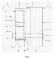
- Fig. 3 is a partial side view of arrangement of Fig. 2 which further illustrates the yoke 6 and pulley box 8.
- the yoke 6 is a solid I-beam with upper flanges 12 that are firmly secured to the bottom of the car floor 5 by a series of bolts or rivets 13.
- Each mounting axle 7 is inserted into a through-hole 14 in the I-beam 6 and secured in position at weld points 15.
- Further elevator components (not shown) such as guide shoes or safety gear can be mounted to a bottom surface 16 of the yoke 6.
- the pulley box 8 is of an inverted U-shape construction having opposing side sections 17 interconnected by an intermediate section 18.
- the pulley box 8 is fabricated from sheet metal.
- Bolts 19 are used to fasten the free edges of the opposing side sections 17 together and thereby improve the overall structural rigidity of the pulley box 8.
- Each diverting pulley 9 is rotatably mounted on a pulley axle 10 via a bearing 20.
- the pulley axles 10 are secured to the opposing side sections 17 of the pulley box 8 in any conventional manner.
- Outer circumferential grooves 21 are provided on the diverting pulley 9 to engage and retain the suspension ropes 11.
- the mounting axles 7 are inserted through the mounting holes 22 in the opposing side sections 17 of the pulley box 8. In use, as the pulleys 9 rotate due to their interaction with the ropes 11, vibrations can be generated in the pulley box 8.
- a resilient ring insert 23 is provided between each of the mounting holes 22 and the respective mounting axles 7 to absorb this vibration.
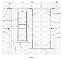
- Fig. 4 shows an alternative embodiment of the invention wherein the relatively heavy I-beam used as the support yoke 6 in the previous embodiment is replaced by a light weight structure.
- the yoke 6 in this instance comprises a pair of vertically aligned sheet metal plates 24 interconnected by rigid web members 25.
- upper flanges 26 on the sheet metal plates 24 are firmly secured to the bottom of the car floor 5 by a series of bolts or rivets 13 and the mounting axles 7 are secured in position at weld points 15.
- a closing plate 27 is provided at opposing ends of the mounting axles 7 such that the pulley box 8 is positioned intermediate the yoke 6 and the closing plate 27.
- the closing plate 27 is formed from a sheet metal plate which is bent over to give a double wall structure. An upper flange 29 of the closing plate 27 is secured to the car floor 5 by a series of bolts or rivets 13 and holes 28 are punched through the closing plate 27 to accommodate the mounting axles 7.
- the closing plate 27 is not fixed to the mounting axles 7 and therefore it cannot transmit any horizontal forces between the pulley box 8 and the car 2. However, any vertical forces between the pulley box 8 and the car 2 are shared between the closing plate 27 and the support yoke 6.
- FIG. 5 An alternative to the previously described underslung arrangements is shown in Fig. 5.
- the car 2 is supported through anti-vibrational pads 33 to a frame 30.
- the frame 30 comprises an upper crosshead 31, a lower yoke 6 and a pair of uprights 32.
- the pulley box 8 in this instance is supported on mounting axles 7 extending from the crosshead 31.
- pulley box 8 and the pulleys 9 can easily be modified to engage with a belt or belts instead of the ropes 11 previously described.
Landscapes
- Engineering & Computer Science (AREA)
- Civil Engineering (AREA)
- Mechanical Engineering (AREA)
- Structural Engineering (AREA)
- Lift-Guide Devices, And Elevator Ropes And Cables (AREA)
- Cage And Drive Apparatuses For Elevators (AREA)
Abstract
Description
- The invention relates to elevators and, in particular, to elevators wherein the elevator cage is mounted on one or more ropes or belts by means of a pulley arrangement.
- Pulley arrangements are commonly used in the elevator industry to mount and drive an elevator cage along ropes arranged within a hoistway in a building. In such an arrangement a pulley box containing two pulleys is mounted on the cage so that as the rope is driven, whether by hydraulic ram or traction sheave, it travels down along one side of the hoistway, engages with one of the pulleys deflecting it through 90°, traverses across the car, engages with the other pulley which deflects it back into the vertical plane, and travels upwards along the opposite side of the hoistway. The pulley box can be mounted to the cage at a point above the passenger car or it can be mounted below the passenger car in which case it is called an underslung arrangement. Such an arrangement is illustrated and described in EP-A2-0983957.
- According to European Standard EN 81-1:1998 and United States ASME Code A17.1-2000, the ratio of the diameter of the pulleys to the nominal diameter of the suspension ropes should be at least 40. Hence, the diameter of each pulley is significantly larger than its width and consequently the height of the pulley box is greater that its width.
- In the prior art as exemplified in Fig. 1, an
upper surface 18 of thepulley box 8 is mounted to the cage either directly to a base of the passenger car or, if the car is contained within a frame, to a lower yoke of the car frame. However, in use, the majority of the vertical forces F are transferred through the lowermost portions A of thepulleys 9. Accordingly, if thepulley box 8 tilts by an angle α, a relatively large bending moment is exerted about the mounting point of the pulley box. The magnitude of the bending moment is defined by the equation M = Fx, where F is the vertical force and x is the horizontal distance between the mounting point on theupper surface 18 of thepulley box 8 and the point of application of the vertical force F. Furthermore, the value x can be expressed as x = L cos α where L is the distance between the mounting point on theupper surface 18 and the lowermost portions A of thepulleys 9. Accordingly, for a given vertical force F and a given tilt angle α, the bending moment M is directly proportional to the value L. However, since the dimension L is principally dependent on the diameter of thepulley 9 which in turn is determined by regulatory bodies as discussed in the preceding paragraph, there is very little scope for reducing the bending moment M. - Hence, both the
pulley box 8 itself and the conventional means for mounting thepulley box 8 to the cage must be capable of withstanding substantial bending moments, otherwise as the cage and the pulley box tilt, the unrestrained bending moment and the tilt angle of the pulley box would progressively increase until eventually the pulley box is permanently deformed or torn from its mounting. - This phenomenon is further exaggerated when the suspension rope is replaced by a belt as any torsion in the belt may be transferred to the pulley box to establish a bending moment about the mounting point even without any tipping of the pulley box.
- Accordingly, the objective of the present invention is to reduce the bending moments about the point at which the pulley box is mounted to the cage. This objective is achieved by providing an elevator cage comprising a car, a support member connected to the car, and a pulley box housing a pair of pulleys mounted to the pulley box by pulley axles, CHARACTERISED IN THAT the pulley box is mounted to the support member through one or more points located below a first line bisecting the pulley axles and above a second line defining a lowest common tangent between the pulleys. In comparison to the prior art, the mounting points of the invention are located closer to the lowermost portions of the pulleys through which the majority of the vertical forces are transferred and hence the bending moments about the mounting points are significantly reduced.
- Preferably, the pulley box is mounted on one or more mounting axles extending from the support member. This arrangement greatly simplifies the assembly of the elevator cage on site and makes horizontal adjustment of the pulley box much easier since the mounting axles are relatively accessible after installation in comparison to the bolts used in the prior art to mount an upper surface of the pulley box to a car floor or to the yoke. Furthermore, the transmission for any vibration from the pulley box to the car can be significantly reduced by providing resilient material between the pulley box and each mounting axle.
- The invention permits an arrangement wherein the support member is a yoke which is fixed directly to a floor of the car. If this configuration is used, it is beneficial to provide a closing plate which is secured to the floor of the car and engages with each mounting axle at an end remote from the yoke such that the pulley box is disposed between the closing plate and the yoke. Accordingly, vertical forces are transmitted not only through the yoke but also through the closing plate. As the force transmitted through the yoke is reduced, it can have a light weight structure in comparison to the prior art. Preferably, the yoke and the closing plate are both formed from sheet metal.
- Alternatively, the support member may form a part of a frame in which the car is suspended. Preferably, the car is resiliently suspended within the frame so that vibrations from the frame are dampened before they reach the car.
- The present invention is herein described by way of specific examples with reference to the accompanying drawings of which:
- Figure 1 is a simplified diagram illustrating the forces exerted on a prior art pulley box;
- Figure 2 is a general schematic front view of an elevator incorporating an elevator cage according to the present invention;
- Figure 3 is a partial side view of the underslung pulley arrangement of Fig. 2;
- Figure 4 is a partial side view of an underslung pulley arrangement according to a second embodiment of the present invention; and
- Figure 5 is a general schematic front view of an elevator incorporating an elevator cage according to a further embodiment of the present invention.
- Throughout the following, features that are common to more than one of the embodiments have the given the same reference numerals so as to avoid unnecessary repetition thereof in the description of the invention.
- Fig. 2 shows an
elevator cage 1 supported by apulley box 8 onropes 11 within an elevator hoistway (not shown). Thecage 1 comprises aconventional car 2 having a plurality ofside walls 3, aroof 4 and afloor 5 defining a transport space for passengers and/or goods. Asupport yoke 6 is mounted directly beneath thefloor 5 of thecar 2. Theyoke 6 has twoparallel mounting axles 7 extending horizontally outwards intocorresponding holes 22 in thepulley box 8. Adiverting pulley 9 is mounted on apulley axle 10 at either end ofpulley box 8 to engage with thesuspension ropes 11. - The
mounting axles 7 and thecorresponding holes 22 are located between a first line P bisecting thepulley axles 10 and a second line Q defining a lowest common tangent between thepulleys 9. In the present embodiment, the lowest common tangent Q corresponds to a line between the lowermost sections A of thepulleys 9. - As the
ropes 11 are driven, they travel down along one side of thecar 2, engage with one of thepulleys 9 deflecting them through 90°, traverse underneath thecar 2, engage with theother pulley 9 which deflects them back into the vertical plane, and travel upwards along the opposite side of thecar 2. - Fig. 3 is a partial side view of arrangement of Fig. 2 which further illustrates the
yoke 6 andpulley box 8. As shown, theyoke 6 is a solid I-beam withupper flanges 12 that are firmly secured to the bottom of thecar floor 5 by a series of bolts or rivets 13. Eachmounting axle 7 is inserted into a through-hole 14 in the I-beam 6 and secured in position atweld points 15. Further elevator components (not shown) such as guide shoes or safety gear can be mounted to abottom surface 16 of theyoke 6. - The
pulley box 8 is of an inverted U-shape construction havingopposing side sections 17 interconnected by anintermediate section 18. Preferably thepulley box 8 is fabricated from sheet metal.Bolts 19 are used to fasten the free edges of theopposing side sections 17 together and thereby improve the overall structural rigidity of thepulley box 8. Eachdiverting pulley 9 is rotatably mounted on apulley axle 10 via abearing 20. Thepulley axles 10 are secured to theopposing side sections 17 of thepulley box 8 in any conventional manner. Outercircumferential grooves 21 are provided on thediverting pulley 9 to engage and retain thesuspension ropes 11. - The
mounting axles 7 are inserted through themounting holes 22 in theopposing side sections 17 of thepulley box 8. In use, as thepulleys 9 rotate due to their interaction with theropes 11, vibrations can be generated in thepulley box 8. Aresilient ring insert 23 is provided between each of themounting holes 22 and therespective mounting axles 7 to absorb this vibration. - Fig. 4 shows an alternative embodiment of the invention wherein the relatively heavy I-beam used as the
support yoke 6 in the previous embodiment is replaced by a light weight structure. Theyoke 6 in this instance comprises a pair of vertically alignedsheet metal plates 24 interconnected byrigid web members 25. As in the previous embodiment,upper flanges 26 on thesheet metal plates 24 are firmly secured to the bottom of thecar floor 5 by a series of bolts or rivets 13 and themounting axles 7 are secured in position atweld points 15. Furthermore, aclosing plate 27 is provided at opposing ends of themounting axles 7 such that thepulley box 8 is positioned intermediate theyoke 6 and theclosing plate 27. Theclosing plate 27 is formed from a sheet metal plate which is bent over to give a double wall structure. Anupper flange 29 of theclosing plate 27 is secured to thecar floor 5 by a series of bolts or rivets 13 andholes 28 are punched through theclosing plate 27 to accommodate themounting axles 7. Theclosing plate 27 is not fixed to themounting axles 7 and therefore it cannot transmit any horizontal forces between thepulley box 8 and thecar 2. However, any vertical forces between thepulley box 8 and thecar 2 are shared between theclosing plate 27 and thesupport yoke 6. - An alternative to the previously described underslung arrangements is shown in Fig. 5. In this embodiment the
car 2 is supported throughanti-vibrational pads 33 to aframe 30. Theframe 30 comprises anupper crosshead 31, alower yoke 6 and a pair ofuprights 32. Thepulley box 8 in this instance is supported on mountingaxles 7 extending from thecrosshead 31. - It will be appreciated by a person skilled in the art, that the
pulley box 8 and thepulleys 9 can easily be modified to engage with a belt or belts instead of theropes 11 previously described.
Claims (9)
- An elevator cage (1) comprising a car (2), a support member (6;31) connected to the car (2), and a pulley box (8) housing a pair of pulleys (9) mounted to the pulley box (8) by pulley axles (10), CHARACTERISED IN THAT the pulley box (8) is mounted to the support member (6;31) through one or more points located below a first line (P) bisecting the pulley axles (10) and above a second line (Q) defining a lowest common tangent between the pulleys (9).
- An elevator cage (1) according to claim 1, wherein the pulley box (8) is mounted on at least one mounting axle (7) extending from the support member (6;31).
- An elevator cage (1) according to claim 2 further comprising resilient material (23) between the pulley box (8) and each mounting axle (7).
- An elevator cage (1) according to claim 2 or claim 3, wherein the support member is a yoke (6) secured to a floor (5) of the car (2).
- An elevator cage (1) according to claim 4 further comprising a closing plate (27) secured to the floor (5) of the car (2) and engaging with each mounting axle (7) at an end remote from the yoke (6).
- An elevator cage (1) according to claim 5, wherein at least one of the yoke (6) and the closing plate (27) are formed from sheet metal.
- An elevator cage (1) according to any of claims 1 to 3, wherein the support member (6;31) forms a part of a frame (30) in which the car (2) is suspended.
- An elevator cage (1) according to claim 7, wherein the support member is a lower yoke (6) of the frame (30).
- An elevator cage (1) according to claim 7, wherein the support member is an upper crosshead (31) of the frame (30).
Priority Applications (1)
| Application Number | Priority Date | Filing Date | Title |
|---|---|---|---|
| EP20050111701 EP1671915B1 (en) | 2004-12-10 | 2005-12-05 | Pulley arrangement for elevators |
Applications Claiming Priority (2)
| Application Number | Priority Date | Filing Date | Title |
|---|---|---|---|
| EP04106489 | 2004-12-10 | ||
| EP20050111701 EP1671915B1 (en) | 2004-12-10 | 2005-12-05 | Pulley arrangement for elevators |
Publications (2)
| Publication Number | Publication Date |
|---|---|
| EP1671915A1 true EP1671915A1 (en) | 2006-06-21 |
| EP1671915B1 EP1671915B1 (en) | 2010-08-04 |
Family
ID=36353853
Family Applications (1)
| Application Number | Title | Priority Date | Filing Date |
|---|---|---|---|
| EP20050111701 Ceased EP1671915B1 (en) | 2004-12-10 | 2005-12-05 | Pulley arrangement for elevators |
Country Status (1)
| Country | Link |
|---|---|
| EP (1) | EP1671915B1 (en) |
Citations (2)
| Publication number | Priority date | Publication date | Assignee | Title |
|---|---|---|---|---|
| EP0983957A2 (en) * | 1998-09-01 | 2000-03-08 | Kabushiki Kaisha Toshiba | Vibration damper for elevator |
| EP1364905A1 (en) * | 2002-05-22 | 2003-11-26 | Inventio Ag | Support beam for elevator car |
-
2005
- 2005-12-05 EP EP20050111701 patent/EP1671915B1/en not_active Ceased
Patent Citations (2)
| Publication number | Priority date | Publication date | Assignee | Title |
|---|---|---|---|---|
| EP0983957A2 (en) * | 1998-09-01 | 2000-03-08 | Kabushiki Kaisha Toshiba | Vibration damper for elevator |
| EP1364905A1 (en) * | 2002-05-22 | 2003-11-26 | Inventio Ag | Support beam for elevator car |
Also Published As
| Publication number | Publication date |
|---|---|
| EP1671915B1 (en) | 2010-08-04 |
Similar Documents
| Publication | Publication Date | Title |
|---|---|---|
| KR100374659B1 (en) | Traction type elevator | |
| KR20010040287A (en) | Traction sheave elevator | |
| CN101588981A (en) | Self-supporting elevator car | |
| EP1405813A1 (en) | Elevator device | |
| EP1364905B1 (en) | Support beam for elevator car | |
| US20130056305A1 (en) | Elevator With Cogged Belt and Pulley and With Counterweight | |
| CA2529342C (en) | Pulley arrangement for elevators | |
| US7481300B2 (en) | Elevator roping arrangement | |
| EP1698581B1 (en) | Machine, lifting system and machine room-less elevator | |
| WO2001074704A1 (en) | Machine-room-less elevator installation structure with traction machine mounted at a rooftop | |
| US8109369B2 (en) | Method of optimizing the weight of a counterweight of an elevator system and elevator system with a counterweight of that kind | |
| EP1671915B1 (en) | Pulley arrangement for elevators | |
| JPH1179612A (en) | Elevator counterweight and car | |
| CN107215746A (en) | A kind of elevator beam mechanism | |
| HK1091460B (en) | Pulley arrangement for elevators | |
| JPH0351285A (en) | Balance adjusting device of elevator cage | |
| CN211169445U (en) | Traction system of long and narrow medical elevator | |
| EP1447370B1 (en) | Elevator | |
| KR102710050B1 (en) | Guide roller device for elevator | |
| WO2005080250A1 (en) | Machine room-less elevator | |
| JP5963530B2 (en) | Elevator car | |
| JP4195044B2 (en) | Elevator | |
| CN210140362U (en) | Goods elevator without machine room | |
| JPH092757A (en) | Guide rail of elevator in unit-type building | |
| HK1171430A (en) | Elevator apparatus |
Legal Events
| Date | Code | Title | Description |
|---|---|---|---|
| PUAI | Public reference made under article 153(3) epc to a published international application that has entered the european phase |
Free format text: ORIGINAL CODE: 0009012 |
|
| AK | Designated contracting states |
Kind code of ref document: A1 Designated state(s): AT BE BG CH CY CZ DE DK EE ES FI FR GB GR HU IE IS IT LI LT LU LV MC NL PL PT RO SE SI SK TR |
|
| AX | Request for extension of the european patent |
Extension state: AL BA HR MK YU |
|
| 17P | Request for examination filed |
Effective date: 20061207 |
|
| REG | Reference to a national code |
Ref country code: HK Ref legal event code: DE Ref document number: 1091460 Country of ref document: HK |
|
| AKX | Designation fees paid |
Designated state(s): AT BE BG CH CY CZ DE DK EE ES FI FR GB GR HU IE IS IT LI LT LU LV MC NL PL PT RO SE SI SK TR |
|
| GRAP | Despatch of communication of intention to grant a patent |
Free format text: ORIGINAL CODE: EPIDOSNIGR1 |
|
| GRAS | Grant fee paid |
Free format text: ORIGINAL CODE: EPIDOSNIGR3 |
|
| GRAA | (expected) grant |
Free format text: ORIGINAL CODE: 0009210 |
|
| AK | Designated contracting states |
Kind code of ref document: B1 Designated state(s): AT BE BG CH CY CZ DE DK EE ES FI FR GB GR HU IE IS IT LI LT LU LV MC NL PL PT RO SE SI SK TR |
|
| REG | Reference to a national code |
Ref country code: GB Ref legal event code: FG4D |
|
| REG | Reference to a national code |
Ref country code: CH Ref legal event code: EP |
|
| REG | Reference to a national code |
Ref country code: IE Ref legal event code: FG4D |
|
| REF | Corresponds to: |
Ref document number: 602005022669 Country of ref document: DE Date of ref document: 20100916 Kind code of ref document: P |
|
| REG | Reference to a national code |
Ref country code: NL Ref legal event code: VDEP Effective date: 20100804 |
|
| REG | Reference to a national code |
Ref country code: HK Ref legal event code: GR Ref document number: 1091460 Country of ref document: HK |
|
| LTIE | Lt: invalidation of european patent or patent extension |
Effective date: 20100804 |
|
| PG25 | Lapsed in a contracting state [announced via postgrant information from national office to epo] |
Ref country code: AT Free format text: LAPSE BECAUSE OF FAILURE TO SUBMIT A TRANSLATION OF THE DESCRIPTION OR TO PAY THE FEE WITHIN THE PRESCRIBED TIME-LIMIT Effective date: 20100804 Ref country code: FI Free format text: LAPSE BECAUSE OF FAILURE TO SUBMIT A TRANSLATION OF THE DESCRIPTION OR TO PAY THE FEE WITHIN THE PRESCRIBED TIME-LIMIT Effective date: 20100804 Ref country code: NL Free format text: LAPSE BECAUSE OF FAILURE TO SUBMIT A TRANSLATION OF THE DESCRIPTION OR TO PAY THE FEE WITHIN THE PRESCRIBED TIME-LIMIT Effective date: 20100804 Ref country code: LT Free format text: LAPSE BECAUSE OF FAILURE TO SUBMIT A TRANSLATION OF THE DESCRIPTION OR TO PAY THE FEE WITHIN THE PRESCRIBED TIME-LIMIT Effective date: 20100804 |
|
| PG25 | Lapsed in a contracting state [announced via postgrant information from national office to epo] |
Ref country code: PL Free format text: LAPSE BECAUSE OF FAILURE TO SUBMIT A TRANSLATION OF THE DESCRIPTION OR TO PAY THE FEE WITHIN THE PRESCRIBED TIME-LIMIT Effective date: 20100804 Ref country code: IS Free format text: LAPSE BECAUSE OF FAILURE TO SUBMIT A TRANSLATION OF THE DESCRIPTION OR TO PAY THE FEE WITHIN THE PRESCRIBED TIME-LIMIT Effective date: 20101204 Ref country code: CY Free format text: LAPSE BECAUSE OF FAILURE TO SUBMIT A TRANSLATION OF THE DESCRIPTION OR TO PAY THE FEE WITHIN THE PRESCRIBED TIME-LIMIT Effective date: 20100804 Ref country code: BG Free format text: LAPSE BECAUSE OF FAILURE TO SUBMIT A TRANSLATION OF THE DESCRIPTION OR TO PAY THE FEE WITHIN THE PRESCRIBED TIME-LIMIT Effective date: 20101104 Ref country code: SI Free format text: LAPSE BECAUSE OF FAILURE TO SUBMIT A TRANSLATION OF THE DESCRIPTION OR TO PAY THE FEE WITHIN THE PRESCRIBED TIME-LIMIT Effective date: 20100804 Ref country code: PT Free format text: LAPSE BECAUSE OF FAILURE TO SUBMIT A TRANSLATION OF THE DESCRIPTION OR TO PAY THE FEE WITHIN THE PRESCRIBED TIME-LIMIT Effective date: 20101206 |
|
| PG25 | Lapsed in a contracting state [announced via postgrant information from national office to epo] |
Ref country code: GR Free format text: LAPSE BECAUSE OF FAILURE TO SUBMIT A TRANSLATION OF THE DESCRIPTION OR TO PAY THE FEE WITHIN THE PRESCRIBED TIME-LIMIT Effective date: 20101105 Ref country code: SE Free format text: LAPSE BECAUSE OF FAILURE TO SUBMIT A TRANSLATION OF THE DESCRIPTION OR TO PAY THE FEE WITHIN THE PRESCRIBED TIME-LIMIT Effective date: 20100804 Ref country code: LV Free format text: LAPSE BECAUSE OF FAILURE TO SUBMIT A TRANSLATION OF THE DESCRIPTION OR TO PAY THE FEE WITHIN THE PRESCRIBED TIME-LIMIT Effective date: 20100804 Ref country code: BE Free format text: LAPSE BECAUSE OF FAILURE TO SUBMIT A TRANSLATION OF THE DESCRIPTION OR TO PAY THE FEE WITHIN THE PRESCRIBED TIME-LIMIT Effective date: 20100804 |
|
| PG25 | Lapsed in a contracting state [announced via postgrant information from national office to epo] |
Ref country code: DK Free format text: LAPSE BECAUSE OF FAILURE TO SUBMIT A TRANSLATION OF THE DESCRIPTION OR TO PAY THE FEE WITHIN THE PRESCRIBED TIME-LIMIT Effective date: 20100804 |
|
| PG25 | Lapsed in a contracting state [announced via postgrant information from national office to epo] |
Ref country code: SK Free format text: LAPSE BECAUSE OF FAILURE TO SUBMIT A TRANSLATION OF THE DESCRIPTION OR TO PAY THE FEE WITHIN THE PRESCRIBED TIME-LIMIT Effective date: 20100804 Ref country code: CZ Free format text: LAPSE BECAUSE OF FAILURE TO SUBMIT A TRANSLATION OF THE DESCRIPTION OR TO PAY THE FEE WITHIN THE PRESCRIBED TIME-LIMIT Effective date: 20100804 Ref country code: IT Free format text: LAPSE BECAUSE OF FAILURE TO SUBMIT A TRANSLATION OF THE DESCRIPTION OR TO PAY THE FEE WITHIN THE PRESCRIBED TIME-LIMIT Effective date: 20100804 Ref country code: RO Free format text: LAPSE BECAUSE OF FAILURE TO SUBMIT A TRANSLATION OF THE DESCRIPTION OR TO PAY THE FEE WITHIN THE PRESCRIBED TIME-LIMIT Effective date: 20100804 Ref country code: EE Free format text: LAPSE BECAUSE OF FAILURE TO SUBMIT A TRANSLATION OF THE DESCRIPTION OR TO PAY THE FEE WITHIN THE PRESCRIBED TIME-LIMIT Effective date: 20100804 |
|
| PLBE | No opposition filed within time limit |
Free format text: ORIGINAL CODE: 0009261 |
|
| STAA | Information on the status of an ep patent application or granted ep patent |
Free format text: STATUS: NO OPPOSITION FILED WITHIN TIME LIMIT |
|
| PG25 | Lapsed in a contracting state [announced via postgrant information from national office to epo] |
Ref country code: ES Free format text: LAPSE BECAUSE OF FAILURE TO SUBMIT A TRANSLATION OF THE DESCRIPTION OR TO PAY THE FEE WITHIN THE PRESCRIBED TIME-LIMIT Effective date: 20101115 |
|
| 26N | No opposition filed |
Effective date: 20110506 |
|
| PG25 | Lapsed in a contracting state [announced via postgrant information from national office to epo] |
Ref country code: MC Free format text: LAPSE BECAUSE OF NON-PAYMENT OF DUE FEES Effective date: 20101231 |
|
| REG | Reference to a national code |
Ref country code: CH Ref legal event code: PL |
|
| REG | Reference to a national code |
Ref country code: DE Ref legal event code: R097 Ref document number: 602005022669 Country of ref document: DE Effective date: 20110506 |
|
| PG25 | Lapsed in a contracting state [announced via postgrant information from national office to epo] |
Ref country code: IE Free format text: LAPSE BECAUSE OF NON-PAYMENT OF DUE FEES Effective date: 20101205 Ref country code: LI Free format text: LAPSE BECAUSE OF NON-PAYMENT OF DUE FEES Effective date: 20101231 Ref country code: CH Free format text: LAPSE BECAUSE OF NON-PAYMENT OF DUE FEES Effective date: 20101231 |
|
| PG25 | Lapsed in a contracting state [announced via postgrant information from national office to epo] |
Ref country code: HU Free format text: LAPSE BECAUSE OF FAILURE TO SUBMIT A TRANSLATION OF THE DESCRIPTION OR TO PAY THE FEE WITHIN THE PRESCRIBED TIME-LIMIT Effective date: 20110205 Ref country code: LU Free format text: LAPSE BECAUSE OF NON-PAYMENT OF DUE FEES Effective date: 20101205 |
|
| PG25 | Lapsed in a contracting state [announced via postgrant information from national office to epo] |
Ref country code: TR Free format text: LAPSE BECAUSE OF FAILURE TO SUBMIT A TRANSLATION OF THE DESCRIPTION OR TO PAY THE FEE WITHIN THE PRESCRIBED TIME-LIMIT Effective date: 20100804 |
|
| REG | Reference to a national code |
Ref country code: FR Ref legal event code: PLFP Year of fee payment: 11 |
|
| REG | Reference to a national code |
Ref country code: FR Ref legal event code: PLFP Year of fee payment: 12 |
|
| REG | Reference to a national code |
Ref country code: FR Ref legal event code: PLFP Year of fee payment: 13 |
|
| PGFP | Annual fee paid to national office [announced via postgrant information from national office to epo] |
Ref country code: FR Payment date: 20171221 Year of fee payment: 13 |
|
| PGFP | Annual fee paid to national office [announced via postgrant information from national office to epo] |
Ref country code: GB Payment date: 20171221 Year of fee payment: 13 |
|
| GBPC | Gb: european patent ceased through non-payment of renewal fee |
Effective date: 20181205 |
|
| PG25 | Lapsed in a contracting state [announced via postgrant information from national office to epo] |
Ref country code: FR Free format text: LAPSE BECAUSE OF NON-PAYMENT OF DUE FEES Effective date: 20181231 |
|
| PG25 | Lapsed in a contracting state [announced via postgrant information from national office to epo] |
Ref country code: GB Free format text: LAPSE BECAUSE OF NON-PAYMENT OF DUE FEES Effective date: 20181205 |
|
| REG | Reference to a national code |
Ref country code: DE Ref legal event code: R084 Ref document number: 602005022669 Country of ref document: DE |
|
| PGFP | Annual fee paid to national office [announced via postgrant information from national office to epo] |
Ref country code: DE Payment date: 20231227 Year of fee payment: 19 |
|
| REG | Reference to a national code |
Ref country code: DE Ref legal event code: R119 Ref document number: 602005022669 Country of ref document: DE |
|
| PG25 | Lapsed in a contracting state [announced via postgrant information from national office to epo] |
Ref country code: DE Free format text: LAPSE BECAUSE OF NON-PAYMENT OF DUE FEES Effective date: 20250701 |