EP1671872A1 - Body reinforcement device for a vehicle - Google Patents
Body reinforcement device for a vehicle Download PDFInfo
- Publication number
- EP1671872A1 EP1671872A1 EP05027408A EP05027408A EP1671872A1 EP 1671872 A1 EP1671872 A1 EP 1671872A1 EP 05027408 A EP05027408 A EP 05027408A EP 05027408 A EP05027408 A EP 05027408A EP 1671872 A1 EP1671872 A1 EP 1671872A1
- Authority
- EP
- European Patent Office
- Prior art keywords
- reinforcement device
- body reinforcement
- mounting
- vehicle
- body frame
- Prior art date
- Legal status (The legal status is an assumption and is not a legal conclusion. Google has not performed a legal analysis and makes no representation as to the accuracy of the status listed.)
- Granted
Links
- 230000002787 reinforcement Effects 0.000 title claims abstract description 185
- 238000013016 damping Methods 0.000 claims abstract description 29
- 238000003466 welding Methods 0.000 claims description 20
- 239000000725 suspension Substances 0.000 claims description 11
- 230000006835 compression Effects 0.000 description 3
- 238000007906 compression Methods 0.000 description 3
- 230000001771 impaired effect Effects 0.000 description 3
- 229910000838 Al alloy Inorganic materials 0.000 description 2
- 229910000831 Steel Inorganic materials 0.000 description 2
- 239000006096 absorbing agent Substances 0.000 description 2
- 238000007789 sealing Methods 0.000 description 2
- 230000035939 shock Effects 0.000 description 2
- 239000010959 steel Substances 0.000 description 2
- CWYNVVGOOAEACU-UHFFFAOYSA-N Fe2+ Chemical compound [Fe+2] CWYNVVGOOAEACU-UHFFFAOYSA-N 0.000 description 1
- 229910045601 alloy Inorganic materials 0.000 description 1
- 239000000956 alloy Substances 0.000 description 1
- 238000004891 communication Methods 0.000 description 1
- 230000008602 contraction Effects 0.000 description 1
- 239000006185 dispersion Substances 0.000 description 1
- 239000000428 dust Substances 0.000 description 1
- 230000000694 effects Effects 0.000 description 1
- 238000004519 manufacturing process Methods 0.000 description 1
- 239000000463 material Substances 0.000 description 1
- 238000000034 method Methods 0.000 description 1
- 238000003825 pressing Methods 0.000 description 1
- 230000000630 rising effect Effects 0.000 description 1
- 238000000926 separation method Methods 0.000 description 1
- XLYOFNOQVPJJNP-UHFFFAOYSA-N water Substances O XLYOFNOQVPJJNP-UHFFFAOYSA-N 0.000 description 1
Images



Classifications
-
- B—PERFORMING OPERATIONS; TRANSPORTING
- B62—LAND VEHICLES FOR TRAVELLING OTHERWISE THAN ON RAILS
- B62D—MOTOR VEHICLES; TRAILERS
- B62D21/00—Understructures, i.e. chassis frame on which a vehicle body may be mounted
- B62D21/15—Understructures, i.e. chassis frame on which a vehicle body may be mounted having impact absorbing means, e.g. a frame designed to permanently or temporarily change shape or dimension upon impact with another body
-
- B—PERFORMING OPERATIONS; TRANSPORTING
- B62—LAND VEHICLES FOR TRAVELLING OTHERWISE THAN ON RAILS
- B62D—MOTOR VEHICLES; TRAILERS
- B62D21/00—Understructures, i.e. chassis frame on which a vehicle body may be mounted
- B62D21/15—Understructures, i.e. chassis frame on which a vehicle body may be mounted having impact absorbing means, e.g. a frame designed to permanently or temporarily change shape or dimension upon impact with another body
- B62D21/157—Understructures, i.e. chassis frame on which a vehicle body may be mounted having impact absorbing means, e.g. a frame designed to permanently or temporarily change shape or dimension upon impact with another body for side impacts
-
- B—PERFORMING OPERATIONS; TRANSPORTING
- B62—LAND VEHICLES FOR TRAVELLING OTHERWISE THAN ON RAILS
- B62D—MOTOR VEHICLES; TRAILERS
- B62D25/00—Superstructure or monocoque structure sub-units; Parts or details thereof not otherwise provided for
- B62D25/20—Floors or bottom sub-units
- B62D25/2009—Floors or bottom sub-units in connection with other superstructure subunits
-
- B—PERFORMING OPERATIONS; TRANSPORTING
- B62—LAND VEHICLES FOR TRAVELLING OTHERWISE THAN ON RAILS
- B62D—MOTOR VEHICLES; TRAILERS
- B62D25/00—Superstructure or monocoque structure sub-units; Parts or details thereof not otherwise provided for
- B62D25/20—Floors or bottom sub-units
- B62D25/2009—Floors or bottom sub-units in connection with other superstructure subunits
- B62D25/2036—Floors or bottom sub-units in connection with other superstructure subunits the subunits being side panels, sills or pillars
-
- B—PERFORMING OPERATIONS; TRANSPORTING
- B60—VEHICLES IN GENERAL
- B60G—VEHICLE SUSPENSION ARRANGEMENTS
- B60G2206/00—Indexing codes related to the manufacturing of suspensions: constructional features, the materials used, procedures or tools
- B60G2206/01—Constructional features of suspension elements, e.g. arms, dampers, springs
- B60G2206/014—Constructional features of suspension elements, e.g. arms, dampers, springs with reinforcing nerves or branches
-
- B—PERFORMING OPERATIONS; TRANSPORTING
- B60—VEHICLES IN GENERAL
- B60G—VEHICLE SUSPENSION ARRANGEMENTS
- B60G2206/00—Indexing codes related to the manufacturing of suspensions: constructional features, the materials used, procedures or tools
- B60G2206/01—Constructional features of suspension elements, e.g. arms, dampers, springs
- B60G2206/60—Subframe construction
- B60G2206/605—Flexible constructions
-
- B—PERFORMING OPERATIONS; TRANSPORTING
- B60—VEHICLES IN GENERAL
- B60R—VEHICLES, VEHICLE FITTINGS, OR VEHICLE PARTS, NOT OTHERWISE PROVIDED FOR
- B60R19/00—Wheel guards; Radiator guards, e.g. grilles; Obstruction removers; Fittings damping bouncing force in collisions
Definitions
- This invention relates to a body reinforcement device for a vehicle; in which a body frame is reinforced while generation of vibration is prevented, so that the riding feeling is improved.
- an aftermarket reinforcement member for example, as disclosed in USP No. 5411311, is in use to increase the strength of the body frame partially in response to running conditions or preference of the driver.
- the reinforcement member disclosed in USP No. 5411311 is formed in a slender shape, and mounted to the upper ends of regions of the body frame called as a pair of left and right suspension towers located in the engine room, so as to connect these suspension towers together. Therefore, the reinforcement member reinforces the body against lateral forces applied to the body from the upper ends of shock absorbers for a front wheel suspension device.
- damping force generation means such as a hydraulic damper or a rubber is provided in the middle of the member in the longitudinal direction, as shown in JP-A-2002-211437.
- the reinforcement member is disposed in the space for passengers, but this unfavorably results in a narrower space for passengers.
- the object of this invention is to provide a body reinforcement device for a vehicle capable of effecting easy improvement in riding feeling through attachment/detachment of the reinforcement member in response to the preference of the driver, without a significant change in the body structure of the existing vehicle and without lowering serviceability and room space properties.
- a body reinforcement device for a vehicle said body reinforcement device extending in a lateral direction of the body frame and comprising a hydraulic damping force generation means generating a damping force against its longitudinal deformation, wherein end portions of the body reinforcement device are configured to be removably attached, from the underside, to a bottom of the body frame exposed downward under the floor surface of the body frame.
- mounting portions for the body reinforcement device to the body frame are left and right side frames extending longitudinally on both sides of the body.
- a body reinforcement device for a vehicle said body reinforcement device extending in a lateral direction of the body frame and comprising a hydraulic damping force generation means generating a damping force against its longitudinal deformation, wherein end portions of the body reinforcement device are configured to be removably attached to bumper reinforcement mounting portions of the body frame.
- a body reinforcement device for a vehicle said body reinforcement device extending in a lateral direction of the body frame and comprising a hydraulic damping force generation means generating a damping force against its longitudinal deformation, wherein end portions of the body reinforcement device are configured to be removably attached to the left and right traction hook mounting portions of the body frame at the end thereof in the longitudinal direction.
- a body reinforcement device for a vehicle said body reinforcement device extending in a lateral direction of the body frame and comprising a hydraulic damping force generation means generating a damping force against its longitudinal deformation, wherein end portions of the body reinforcement device are configured to be removably attached to left and right lower arm mounting portion of a suspension device of the vehicle.
- said body reinforcement device might be formed in a slender shape
- hydraulic damping force generation means might be provided in a middle portion of the body reinforcement device.
- the body reinforcement device for a vehicle further comprises a pair of mounting members at its ends attachable to the vehicle body, a hydraulic damper having a hydraulic cylinder welded to one of the mounting members, and an extension rod for connecting a piston rod of the hydraulic damper with the other one of the mounting members.
- the hydraulic cylinder of the hydraulic damper comprises a cylinder tube closed at one end by a welding cone provided at a center of a support plate of one of the mounting member.
- the body reinforcement device for a vehicle further comprises a piston fitted in a cylinder tube, defining a first oil chamber and a second oil chamber in the cylinder tube, and being fixed to the piston rod, wherein the first oil chamber is formed between the piston and a free piston fitted for movement in the cylinder tube, and wherein the free piston defines the first oil chamber and a high pressure gas chamber in one end portion of the cylinder tube.
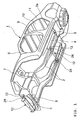
- Fig. 1 is a perspective view of a body frame equipped with a body reinforcement device according to this embodiment.
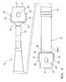
- Fig. 2 is a plan view of the body reinforcement device for a vehicle according to this embodiment.
- Fig. 2 is a view of the reinforcement device, with a welding cone located upward of a mounting plate.
- Fig. 3 is a vertical sectional view of the body reinforcement device for a vehicle according to this embodiment.
- the monocoque body 1 comprises, as shown in Fig. 1, side frames 2, 2 provided in a pair in the lateral direction of the body and extending longitudinally on both sides of the body; a floor panel 4 forming an under body 3, together with these side frames 2, 2; a bumper reinforcement 5 and a cross member 6 extending crosswise between the pair of side frames 2, 2 at the forward ends; a front fender apron 7; a front pillar 8; a center pillar 9; a roof 10; a rear pillar 11; a side shell 2a; and the like.
- the monocoque body 1 is formed of a plurality of pressed plates or pipes welded and assembled together.
- body reinforcement devices 12 are mounted for attachment/detachment to the side frame 2 and the mounting portion for the bumper reinforcement 5.
- the body reinforcement devices 12 are each formed in a slender shape, and are mounted for attachment/detachment to the side frame 2 and the bumper reinforcement 5 such that they are expandable in the lateral direction of the body, as shown in Fig. 1.
- Mounting seats 13 of the side frame 2 on which the body reinforcement device 12 is mounted have approximately the same height as the bottom surface of the floor panel 4 and are positioned at the bottom of the body exposed downward even after completion of the body.
- the mounting seat 13 is formed with a flat surface for the mounting of the body reinforcement device 12 and having a fixing nut embedded, though not shown in the figure.
- This mounting seat 13 represents the term "mounting portion to the body frame" referred to in the following.
- the bumper reinforcement 5 of this embodiment is mounted, at both ends, to the mounting seats 13 (bumper reinforcement mounting portions) provided at the forward ends of the side frames 2, 2 with mounting bolts 24 to be described later.
- the mounting seat 13 represents the "bumper reinforcement mounting portion" referred to in the following.
- the bumper reinforcement 5 may be welded at the forward ends of the side frames 2, 2.
- the bumper reinforcement 5 can be formed by an extruded material made of aluminum alloy or a channel made of aluminum alloy or ferrous alloy.
- the body reinforcement device 12 At both ends of the bumper reinforcement 5 in the lateral direction is mounted for attachment/detachment the body reinforcement device 12 with mounting bolts 24 in a relation of being fastened together.
- the bumper reinforcement 5 is housed inside a bumper (not shown), together with the body reinforcement device 12.
- the body reinforced device 12 includes, as shown in Fig. 2 and Fig. 3, mounting members 14, 15 at both ends attached to the body; a hydraulic damper 17 having a hydraulic cylinder 16 welded to one mounting member 14 of these mounting members; and an extension rod 19 for connecting a piston rod 18 of the hydraulic damper 17 and the other mounting member 15.
- the mounting members 14, 15 are each formed in a given shape by a steel plate bent, and includes a mounting plate 21 attached to the body; a support plate 22 rising from one end of the mounting plate 21; and a pair of reinforcement ribs 23 for connecting the sides of these plates together.
- the mounting plate 21 is formed with an elongated hole 25 for a mounting bolt 24 (see Fig. 1) with which the mounting member 14, 15 is attached to the body, as shown in Fig. 2.
- the elongated hole 25 is formed to be larger in the lateral direction on Fig. 2, that is, in the direction perpendicular to the main face of the support plate 22.
- the mounting members 14, 15 are each attached to the body such that the main face of the support plate 22 is directed laterally of the body. Therefore, positions, at which these mounting members 14, 15 are attached, can be finely adjusted in the lateral direction of the body by as much as the moving allowance of the elongated hole 25 relative to the mounting bolt 24.
- the support plate 22 is provided at its center with a welding cone 6.
- the cone 26 is formed by the support plate 22 pushed out at the center into a conical shape in the direction of separation from the mounting plate 21.
- the reinforcement rib 23 is formed with a mounting hole 27 for a damping force measuring instrument.
- the hydraulic damper 17 includes, as shown in Fig. 3, the hydraulic cylinder 16 having a cylinder tube 31 closed at one end by the one mounting member 14, and a choke 33 provided in a piston 32 of the hydraulic cylinder 16.
- the welding cone 26 of the mounting member 14 is inserted therein.
- This welding is performed by the conventionally well-known projection method, in which case the welding cone 26 is fitted in the opening of the cylinder tube 31 such that the connecting portion of both parts makes line contact.
- the projection welding is performed by pressing the welding cone 26 and the cylinder tube 31 being combined as described above, against each other along the axial direction and energizing them with a high tension current.
- the cylinder tube 31 is closed at the other end by a rod guide 34 for supporting the piston rod 18 for movement.
- the rod guide 34 is fitted in the cylinder tube 31 and fixed to the cylinder tube 31 by circlips 34a, 34b.
- seal members 35, 36 for sealing its portions where the piston rod 18 penetrates the rod guide.
- the piston 32 is formed in a circular shape in section so as to be fitted in the cylinder tube 31, defining a first oil chamber 37 and a second oil chamber 38 in the cylinder tube 31, and fixed to the piston rod 18 passing through the axial center with a fixing nut.
- the first oil chamber 37 is formed between the piston 32 and a free piston 39 fitted for movement in the cylinder tube 31.
- the free piston 39 defines the first oil chamber 37.
- a high pressure gas chamber 40 in one end portion of the cylinder tube 31.
- the high pressure gas chamber 40 is filled with N 2 gas at high pressure.
- a screw 41 With a sealing rubber for filling the high pressure gas chamber 40 with N 2 gas.
- the piston 32 is biased in the direction of contraction of the hydraulic cylinder 16 by a compression coil spring 42 elastically fitted between the piston and the rod guide 34.
- the compression coil spring 42 is used for counteracting gas reaction force exerted on the piston 32 through the working oil in the cylinder tube 31.
- the gas reaction force is produced by the pressure receiving area of the piston 32 on the side of the second oil chamber 38 being smaller than that on the side of the first oil chamber 37.
- the piston 32 since the working oil in the first and second oil chambers 37, 38 is pressurized by the N 2 gas at high pressure, the piston 32 receives a gas reaction force corresponding to the foregoing difference in pressure receiving area and is biased by the gas reaction force in the direction of expansion of the hydraulic cylinder 16.
- a length of the damper 17 obtained when the gas reaction force is counteracted by the spring force of the compression coil spring 42 to be balanced, is the free length, and the N 2 gas pressure is adjusted such that the free length is in agreement with the mounting size to the body.
- the initial load becomes zero when the damper is mounted to the body, and even if a small load is exerted, the reinforcement device 12 contracts immediately in quick response, effecting generation of the damping force.
- the choke 33 provided in the piston 32 is of the same structure as that used in the shock absorber for suspension devices or the like, and is formed of first and second check valves 47, 48 provided with disk springs 45, 46 for opening/closing openings at one ends of communication holes 43, 44 provided in the piston 32.
- the disk springs 45, 46 are each formed in an annular shape and formed of a plurality of spring pieces on top of one another, the inside circumferential surfaces of which are fixed to the piston 32.
- the extension rod 19 for connecting the forward end of the piston rod 18 and the other mounting member 15 is formed by a pipe, screwed at one end onto the forward end of the piston rod 18, and welded at the other end to the other mounting member 15.
- the connecting portion of the extension rod 19 and the piston rod 18 is configured such that a male screw 18a formed on the piston rod 18 is fitted in a female screw 19a of the extension rod 19 and these screws are fastened by a lock nut 49.
- This mounting structure of the extension rod 19 by screws allows a changing free length of the reinforcement device 12 due to dispersion of the N 2 gas pressure to be finely adjusted.
- the screwing section is covered by a rubber boot 51 provided to connect the extension rod 19 and the cylinder tube 31.
- the rubber boot 51 is used for preventing dust or muddy water from sticking to the piston rod 18, is formed in the shape of a conical pipe, and is fixed at one end to the outside circumferential surface of the cylinder tube 31 and at the other end to the outside circumferential surface of the extension rod 19.
- Welding of the extension rod 19 to the other mounting member 15 is performed by the projection welding as in the welding of the mounting member 14 to the cylinder tube 31. That is, this welding is performed such that when the welding cone 26 of the other mounting member 15 is fitted at the forward end in the extension rod 19 and both parts are brought into line contact with each other, they are pressed against each other and energized with an electric current. Such a welding allows the extension rod 19 and the welding cone 26 to be easily positioned on the same axis.
- the mounting plates 21 of the mounting members 14, 15, while being held at positions higher than the other parts, are put on the mounting seats 13 of the side frame 2 from below, followed by fastening the mounting bolts 24.
- the body reinforcement device 12 can be removed easily from the body when the mounting bolts 24 are unfastened and the mounting members 14, 15 are removed from the side frames 2, 2.
- the body reinforcement device 12 to be mounted on the bumper reinforcement 5 of the monocoque body 1, the mounting plates 21 of the mounting members 14, 15 are fastened, with the mounting bolts 24, to the mounting seats 13 of the monocoque body 1, together with the bumper reinforcement 5.
- the body reinforcement device 12 can also be removed easily from the mounting portions for the bumper reinforcement 5 when the mounting bolts 24 are removed.
- the body reinforcement device 12 mounted to the side frame 2 and the bumper reinforcement 5 as described above, lateral rigidity of the monocoque body 1 can be improved. Therefore, the riding feeling is different in a vehicle in which the body reinforcement device 12 is mounted and in a vehicle in which the body reinforcement device 12 is removed.
- the body reinforcement device 12 can be attached/detached with respect to the body from the underside.
- the body reinforcement device 12 can easily be attached/detached from below.
- the mounting can be realized if only mounting seats 13 are provided on the side frame 2 of the existing monocoque body 1.
- the body reinforcement device 12 mounted to the mounting portions (on the mounting seats 13) for the bumper reinforcement 5, is exposed to the outside of the body, together with the bumper reinforcement 5. Therefore, the body reinforcement device 12 can easily be attached/detached with respect to the bumper reinforcement 5, with the bumper removed.
- lateral rigidity of the monocoque body 1 is improved adequately while generation of vibration is suppressed, effecting improvement in riding feeling.
- body reinforcement device 12 of this embodiment utilizes the space under the body or the space inside the bumper, no serviceability or room space properties are impaired.
- the body reinforcement device 12 is mounted to the bumper reinforcement mounting portions (on the mounting seats 13), being fastened together with the bumper reinforcement 5, the body reinforcement device 12 can be mounted on the mounting seats 13 of the monocoque body in a region near the bumper reinforcement 5 on its mounting seats. If the bumper reinforcement 5 is welded to the mounting seats 13, the body reinforcement device 12 is mounted for attachment/detachment directly to the bumper reinforcement 5 on the front face or the bottom surface.
- the body frame to which the body reinforcement device 12 according to this embodiment is mounted may be formed as shown in Fig. 4 and Fig. 5.
- Fig. 4 is a perspective view showing another embodiment of the body reinforcement device for a vehicle
- Fig. 5 is a perspective view showing on an enlarged scale the mounting portion for the body reinforcement device.
- like parts as described in Fig. 1-Fig. 3 are designated by like reference numerals, and detailed description is not repeated as appropriate.
- a body frame 61 shown in Fig. 4 is of a conventionally well-known ladder type, and includes a pair of side frames 62, 62 extending longitudinally on both left and right sides of the body, a plurality of cross members 63 extending crosswise between the side frames 62, 62, and the like.
- the body reinforcement device 12 of this embodiment has the same structure as that of the first embodiment, and as shown in Fig. 5, the device 12, extending in the lateral direction of the body, is mounted for attachment/detachment on the bottom surfaces (mounting seats) of the side frames 62, 62.
- this embodiment is constructed such that the body reinforcement device 12 is mounted to the ladder type body frame 61, this body reinforcement device 12 improves lateral rigidity of the body frame 61 adequately as well as the riding feeling, while generation of vibration is suppressed, thereby producing the same effect as in the first embodiment.
- the body reinforcement device for a vehicle can also be mounted to the body frame, together with traction hooks, as shown in Fig. 6 and Fig. 7.
- Fig. 6 is a perspective view showing an embodiment of the body reinforcement device for a vehicle, which is mounted on the rear faces of traction hook supports.
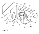
- Fig. 7 is a perspective view showing the embodiment of the body reinforcement device for a vehicle, which is mounted on the bottom surfaces of traction hook supports.
- like parts as described in Fig. 1-Fig. 5 are designated by like reference numerals, and detailed description is not repeated as appropriate.
- the traction hooks 72 are each formed, for example, by an eyebolt, and are mounted to a pair of left and right side frames (not shown) at the rear ends through traction hook supports 73, respectively.
- the traction hook 72 is mounted, protruding downward, to the traction hook support 73.
- the body reinforcement device 12 shown in Fig. 6 is mounted to the supports 73 for attachment/detachment, extending crosswise between the pair of left and right supports 73.
- a traction hook 74 shown in Fig. 7 is formed by a steel plate 75, in the L-shape in section, provided with an elongated hole 77 in the vertical extension 76.
- the traction hook 74 is mounted for attachment/detachment to the rear end of the side frame on the bottom surface, with a horizontal extension 78 formed integrally at the upper end of the vertical extension 76 and fastened together with the mounting member 14, 15 of the body reinforcement device 12.
- the body reinforcement device 12 for a vehicle improves lateral rigidity of the monocoque body 1 adequately wile generation of vibration is suppressed between the pairs of traction hooks 72, 72, 74, 74, effecting improvement in riding feeling.
- the body reinforcement device 12 of this embodiment is mounted to the traction hook mounting portions where the rigidity of body is generally high, providing reliable mounting.
- the mounting members 14, 15 of the body reinforcement device 12 are mounted to the body frame, being fastened together with the traction hooks 72, 74, mounting seats only for the mounting of the body reinforcement device 1 to the body frame are unnecessary. Therefore, the structure as shown in this embodiment allows the body reinforcement device 12 to be mounted to the body frame even more easily.
- the body reinforcement device 12 may be mounted to the body frame near a region where the traction hook supports 73 or plates 75 are mounted.
- body reinforcement device 12 may be mounted to the mounting portions for traction hooks (not shown) provided at the forward end of the body.
- the body reinforcement device 12 for a vehicle can be mounted for attachment/detachment to the lower arm mounting portion of a suspension device in the body frame of a vehicle, as shown in Fig. 8.
- Fig. 8 is a perspective view showing an embodiment of the body reinforcement device for a vehicle, which is mounted to the lower arm mounting portion.
- like parts as described in Fig. 1-Fig. 5 are designated by like reference numerals, and detailed description is not repeated as appropriate.
- a body frame 81 of a vehicle shown in Fig. 8 is formed with a vertical wall 82 directed longitudinally of the body and extending from one end to the other end thereof in the lateral direction.
- the bracket 85 is provided to be in a pair with respect to a bracket for supporting the other lower arm (not shown) in the lateral direction of the body. That is, the vertical wall 82 constitutes a mounting seat (left and right-lower arm mounting portion) for the bracket 85 of the lower arm 84 to be mounted thereon.
- the body reinforcement device 12 for a vehicle is disposed between the pair of brackets 85, 85, and mounted for attachment/detachment to the vertical wall 82. Therefore, according to this embodiment, since lateral rigidity of portions of the body frame 81 on which lateral pushing forces are exerted from the left and right lower arms, is improved adequately while generation of vibration is suppressed, the riding feeling can be improved efficiently.
- the body reinforcement device 12 utilizes the existing lower arm mounting seat (vertical wall 82), the device can be mounted easily compared with when a special mounting seat is provided on the body frame.
- the body reinforcement device 12 positioned as described above, allows the body frame 81 to be reinforced efficiently against the pushing force by the lower arm 84 of the suspension device 83.
- the body reinforcement device 12 may be mounted to the vertical wall 82, being fastened together with the brackets 85.
- the description above discloses (amongst others) an embodiment of a body reinforcement device formed in a slender shape and provided in the middle with hydraulic damping force generation means for generating a damping force against its deformation in the longitudinal direction, in which the longitudinal direction is defined as a lateral direction of the body, and the body reinforcement device is mounted at both ends, for attachment/detachment from the underside, to the bottom of a body frame exposed downward under the floor surface of the body frame.
- the body reinforcement device when mounted to the body frame, improves lateral rigidity of the body frame adequately and improves the riding feeling, while suppressing generation of vibration.
- the body reinforcement device can easily be attached to and detached from the body if the body is lifted, for example, by a jack or the like.
- exposed downward doesn't necessarily means that the body frame is exposed at all times, but includes a case, for example, that an under cover is provided for attachment/detachment to protect the bottom surface of the body frame, and the body frame is exposed if the under cover is removed.
- mounting can be realized if only mounting seats or mounting brackets are provided on the existing body.
- the body reinforcement device for a vehicle can be provided, which is capable of effecting easy improvement in riding feeling without significant change in the body structure of the existing vehicle. Further, since the body reinforcement device according to the embodiment utilizes the space under the body, no serviceability or room space properties are impaired.
- the body reinforcement device is mounted to the left and right side frames of a body frame extending in the longitudinal direction on both sides of the body.
- lateral rigidity of the side frame which is essential for a body frame can be improved adequately while generation of vibration is suppressed, the riding feeling can be improved efficiently.
- the body reinforcement device is mounted to the left and right-traction hook mounting portions of the body frame at the ends of the body in the longitudinal direction.
- the left and right-traction hook mounting portions herein referred to, include, in addition to the regions where supporting bodies with traction hooks are mounted to the body frame, regions adjacent to the supporting bodies mounted to the body frame.
- the body reinforcement device for a vehicle is mounted at the traction hook mounting portions having high rigidity in general, thereby effecting reliable mounting of the reinforcement device. If the reinforcement device is mounted to the body frame, being fastened together with the traction hooks, it can be mounted to the body frame more easily and economically.
- the body reinforcement device is mounted to the left and right-lower arm mounting portion of a suspension device in the body frame.
- the left and right-lower arm mounting portion herein referred to, includes, in addition to the region where the support brackets for supporting the lower arms are mounted to the body frame, regions adjacent to the brackets mounted to the body frame.
- lateral rigidity of the body frame at portions on which lateral pushing forces are exerted from the left and right lower arms can be improved adequately while generation of vibration is suppressed, the riding feeling can be improved efficiently.
- the device can be mounted easily and economically compared with when special seats are provided on the body frame.
- a body reinforcement device for a vehicle formed in a slender shape and provided in the middle with hydraulic damping force generation means for generating a damping force against its deformation in the longitudinal direction, in which the longitudinal direction is defined as a lateral direction of the body, and the body reinforcement device is mounted at both ends, for attachment/detachment, to the bumper reinforcement mounting portions of a body frame.
- the bumper reinforcement mounting portions herein referred to, include, in addition to the regions where the bumper reinforcement is mounted to the body frame, a region adjacent to the bumper reinforcement mounted to the body frame.
- the device mounted to the bumper reinforcement mounting portions lateral rigidity of the body frame can be improved adequately while generation of vibration is suppressed, improving the riding feeling.
- the device is exposed to the outside of the body, together with the bumper reinforcement, providing easy attachment/detachment with respect to the bumper reinforcement mounting portions in this condition. Further, since the device utilizes the space inside the bumper, no serviceability or room space properties are impaired.
- mounting can be realized if only the device is fixed to the body frame together with the bumper reinforcement, or it is fixed to the bumper reinforcement itself fixed to the body frame, or further it is fixed to the body frame near the portions at which the bumper reinforcement is fixed to the frame, for example.
- the body reinforcement device for a vehicle can be provided, which is capable of effecting easy and economical improvement in riding feeling without significant change in the body structure of the existing vehicle.
- a body reinforcement device for a vehicle in order to provide a body reinforcement device for a vehicle capable of effecting easy improvement in riding feeling through attachment/detachment of the reinforcement member depending on the preference of the driver, without a significant change in the existing vehicle body structure and without lowering serviceability and room space properties, a body reinforcement device for a vehicle is formed in a slender shape and provided in the middle with a hydraulic damper 17 for generating a damping force against its deformation in the, longitudinal direction.
- the longitudinal direction is defined as a lateral direction of the body, and the reinforcement device is mounted at both ends, for attachment/detachment from the underside, to the bottom of a monocoque body 1 exposed downward under a floor panel 4 of the monocoque body.
Landscapes
- Engineering & Computer Science (AREA)
- Chemical & Material Sciences (AREA)
- Combustion & Propulsion (AREA)
- Transportation (AREA)
- Mechanical Engineering (AREA)
- Body Structure For Vehicles (AREA)
- Manufacture Of Alloys Or Alloy Compounds (AREA)
- Vehicle Body Suspensions (AREA)
- ing And Chemical Polishing (AREA)
Abstract
Description
- This invention relates to a body reinforcement device for a vehicle; in which a body frame is reinforced while generation of vibration is prevented, so that the riding feeling is improved.
- Hitherto, in the body frames of some motor vehicles, an aftermarket reinforcement member, for example, as disclosed in USP No. 5411311, is in use to increase the strength of the body frame partially in response to running conditions or preference of the driver. The reinforcement member disclosed in USP No. 5411311, is formed in a slender shape, and mounted to the upper ends of regions of the body frame called as a pair of left and right suspension towers located in the engine room, so as to connect these suspension towers together. Therefore, the reinforcement member reinforces the body against lateral forces applied to the body from the upper ends of shock absorbers for a front wheel suspension device.
- However, the foregoing reinforcement member might impair the riding feeling because of generation of vibration when a load applied to the member is released immediately after the member is compressed. For such generation of vibration to be prevented, in some cases, damping force generation means such as a hydraulic damper or a rubber is provided in the middle of the member in the longitudinal direction, as shown in JP-A-2002-211437.
- However, since there is not much space left in the engine room due to the arrangement of an engine and other equipment, and the hood height is limited, determination of disposition of the reinforce member is problematic. In addition, since the member extends across the upper space in the engine room, serviceability of the engine and other equipment is lowered.
- On the other hand, it is possible that the reinforcement member is disposed in the space for passengers, but this unfavorably results in a narrower space for passengers.
- In view of the foregoing, the object of this invention is to provide a body reinforcement device for a vehicle capable of effecting easy improvement in riding feeling through attachment/detachment of the reinforcement member in response to the preference of the driver, without a significant change in the body structure of the existing vehicle and without lowering serviceability and room space properties.
- This objective is solved in an inventive manner by a body reinforcement device for a vehicle, said body reinforcement device extending in a lateral direction of the body frame and comprising a hydraulic damping force generation means generating a damping force against its longitudinal deformation, wherein end portions of the body reinforcement device are configured to be removably attached, from the underside, to a bottom of the body frame exposed downward under the floor surface of the body frame.
- Preferably, mounting portions for the body reinforcement device to the body frame are left and right side frames extending longitudinally on both sides of the body.
- The objective is further solved by a body reinforcement device for a vehicle, said body reinforcement device extending in a lateral direction of the body frame and comprising a hydraulic damping force generation means generating a damping force against its longitudinal deformation, wherein end portions of the body reinforcement device are configured to be removably attached to bumper reinforcement mounting portions of the body frame.
- The objective is still further solved by a body reinforcement device for a vehicle, said body reinforcement device extending in a lateral direction of the body frame and comprising a hydraulic damping force generation means generating a damping force against its longitudinal deformation, wherein end portions of the body reinforcement device are configured to be removably attached to the left and right traction hook mounting portions of the body frame at the end thereof in the longitudinal direction.
- This objective is yet further solved by a body reinforcement device for a vehicle, said body reinforcement device extending in a lateral direction of the body frame and comprising a hydraulic damping force generation means generating a damping force against its longitudinal deformation, wherein end portions of the body reinforcement device are configured to be removably attached to left and right lower arm mounting portion of a suspension device of the vehicle.
- Within the above body reinforcement devices for a vehicle, said body reinforcement device might be formed in a slender shape
- Further, the hydraulic damping force generation means might be provided in a middle portion of the body reinforcement device.
- According to another embodiment, the body reinforcement device for a vehicle further comprises a pair of mounting members at its ends attachable to the vehicle body, a hydraulic damper having a hydraulic cylinder welded to one of the mounting members, and an extension rod for connecting a piston rod of the hydraulic damper with the other one of the mounting members.
- Therein, it is further preferable if the hydraulic cylinder of the hydraulic damper comprises a cylinder tube closed at one end by a welding cone provided at a center of a support plate of one of the mounting member.
- Additionally, it is preferable if the body reinforcement device for a vehicle further comprises a piston fitted in a cylinder tube, defining a first oil chamber and a second oil chamber in the cylinder tube, and being fixed to the piston rod, wherein the first oil chamber is formed between the piston and a free piston fitted for movement in the cylinder tube, and wherein the free piston defines the first oil chamber and a high pressure gas chamber in one end portion of the cylinder tube.
- In the following, the present invention is explained in greater detail with respect to several embodiments thereof in conjunction with the accompanying drawings, wherein:
- Fig. 1
- is a perspective view of a body frame equipped with a body reinforcement device for a vehicle according to an embodiment,
- Fig. 2
- is a plan view of the body reinforcement device for a vehicle according to this embodiment,
- Fig. 3
- is a vertical sectional view of the body reinforcement device for a vehicle according to this embodiment,
- Fig. 4
- is a perspective view showing another embodiment of the body reinforcement device for a vehicle according to another embodiment,
- Fig. 5
- is a perspective view showing on an enlarged scale the mounting portion for the body reinforcement device of Fig. 4,
- Fig. 6
- is a perspective view showing an embodiment of the body reinforcement device for a vehicle according to another embodiment, which is mounted on the rear faces of traction hook supports,
- Fig. 7
- is a perspective view showing the embodiment of the body reinforcement device of Fig. 6 for a vehicle, which is mounted on the bottom surfaces of traction hook supports, and
- Fig. 8
- is a perspective view showing another embodiment of the body reinforcement device for a vehicle according to this invention, which is mounted to the lower arm mounting portion.
- Now, an embodiment of the body reinforcement device for a vehicle will be described in detail with reference to Fig. 1-Fig. 3.
- Fig. 1 is a perspective view of a body frame equipped with a body reinforcement device according to this embodiment. Fig. 2 is a plan view of the body reinforcement device for a vehicle according to this embodiment. Fig. 2 is a view of the reinforcement device, with a welding cone located upward of a mounting plate. Fig. 3 is a vertical sectional view of the body reinforcement device for a vehicle according to this embodiment.
- In these figures, designated by reference numeral 1 is a monocoque body for a car as a body frame of this embodiment. The monocoque body 1 comprises, as shown in Fig. 1,
side frames floor panel 4 forming an underbody 3, together with theseside frames bumper reinforcement 5 and across member 6 extending crosswise between the pair ofside frames front fender apron 7; afront pillar 8; acenter pillar 9; aroof 10; arear pillar 11; aside shell 2a; and the like. The monocoque body 1 is formed of a plurality of pressed plates or pipes welded and assembled together. - In the monocoque body 1 of this embodiment,
body reinforcement devices 12 according to this embodiment are mounted for attachment/detachment to theside frame 2 and the mounting portion for thebumper reinforcement 5. - The
body reinforcement devices 12 are each formed in a slender shape, and are mounted for attachment/detachment to theside frame 2 and thebumper reinforcement 5 such that they are expandable in the lateral direction of the body, as shown in Fig. 1. -
Mounting seats 13 of theside frame 2 on which thebody reinforcement device 12 is mounted, have approximately the same height as the bottom surface of thefloor panel 4 and are positioned at the bottom of the body exposed downward even after completion of the body. Themounting seat 13 is formed with a flat surface for the mounting of thebody reinforcement device 12 and having a fixing nut embedded, though not shown in the figure. Thismounting seat 13 represents the term "mounting portion to the body frame" referred to in the following. - The
bumper reinforcement 5 of this embodiment is mounted, at both ends, to the mounting seats 13 (bumper reinforcement mounting portions) provided at the forward ends of theside frames bolts 24 to be described later. Themounting seat 13 represents the "bumper reinforcement mounting portion" referred to in the following. Thebumper reinforcement 5 may be welded at the forward ends of theside frames bumper reinforcement 5 can be formed by an extruded material made of aluminum alloy or a channel made of aluminum alloy or ferrous alloy. - At both ends of the
bumper reinforcement 5 in the lateral direction is mounted for attachment/detachment thebody reinforcement device 12 with mountingbolts 24 in a relation of being fastened together. Thebumper reinforcement 5 is housed inside a bumper (not shown), together with thebody reinforcement device 12. - The body reinforced
device 12 includes, as shown in Fig. 2 and Fig. 3, mountingmembers hydraulic damper 17 having ahydraulic cylinder 16 welded to onemounting member 14 of these mounting members; and anextension rod 19 for connecting apiston rod 18 of thehydraulic damper 17 and theother mounting member 15. - The
mounting members mounting plate 21 attached to the body; asupport plate 22 rising from one end of themounting plate 21; and a pair ofreinforcement ribs 23 for connecting the sides of these plates together. - The
mounting plate 21 is formed with anelongated hole 25 for a mounting bolt 24 (see Fig. 1) with which themounting member elongated hole 25 is formed to be larger in the lateral direction on Fig. 2, that is, in the direction perpendicular to the main face of thesupport plate 22. - The
mounting members support plate 22 is directed laterally of the body. Therefore, positions, at which these mountingmembers elongated hole 25 relative to themounting bolt 24. - The
support plate 22 is provided at its center with awelding cone 6. Thecone 26 is formed by thesupport plate 22 pushed out at the center into a conical shape in the direction of separation from themounting plate 21. - The
reinforcement rib 23 is formed with a mountinghole 27 for a damping force measuring instrument. - The
hydraulic damper 17 includes, as shown in Fig. 3, thehydraulic cylinder 16 having acylinder tube 31 closed at one end by the one mountingmember 14, and achoke 33 provided in apiston 32 of thehydraulic cylinder 16. - To one end of the
cylinder tube 31 is welded thewelding cone 26 of the mountingmember 14 being inserted therein. This welding is performed by the conventionally well-known projection method, in which case thewelding cone 26 is fitted in the opening of thecylinder tube 31 such that the connecting portion of both parts makes line contact. - As a result of the
welding cone 26 inserted into thecylinder tube 31 to be fitted, even if thecylinder tube 31 is formed tapered at the edge, thewelding cone 26 and thecylinder tube 31 are brought into line contact with each other while positioned approximately on the same axis. That is, compared with when seal-welding is performed, with thecylinder tube 31 abutted at its opening end against the closing plate, manufacturing of thecylinder tube 31 becomes easier, effecting cost reduction as well as improvement in external appearance. - The projection welding is performed by pressing the
welding cone 26 and thecylinder tube 31 being combined as described above, against each other along the axial direction and energizing them with a high tension current. - The
cylinder tube 31 is closed at the other end by arod guide 34 for supporting thepiston rod 18 for movement. Therod guide 34 is fitted in thecylinder tube 31 and fixed to thecylinder tube 31 bycirclips - At both ends of the
rod guide 34 in the axial direction are providedseal members piston rod 18 penetrates the rod guide. - The
piston 32 is formed in a circular shape in section so as to be fitted in thecylinder tube 31, defining afirst oil chamber 37 and asecond oil chamber 38 in thecylinder tube 31, and fixed to thepiston rod 18 passing through the axial center with a fixing nut. - The
first oil chamber 37 is formed between thepiston 32 and afree piston 39 fitted for movement in thecylinder tube 31. Thefree piston 39 defines thefirst oil chamber 37. and a highpressure gas chamber 40 in one end portion of thecylinder tube 31. The highpressure gas chamber 40 is filled with N2 gas at high pressure. Into thewelding cone 26 of the mountingmember 14 forming a wall of the highpressure gas chamber 40 is fitted ascrew 41 with a sealing rubber for filling the highpressure gas chamber 40 with N2 gas. - The
piston 32 is biased in the direction of contraction of thehydraulic cylinder 16 by acompression coil spring 42 elastically fitted between the piston and therod guide 34. Thecompression coil spring 42 is used for counteracting gas reaction force exerted on thepiston 32 through the working oil in thecylinder tube 31. The gas reaction force is produced by the pressure receiving area of thepiston 32 on the side of thesecond oil chamber 38 being smaller than that on the side of thefirst oil chamber 37. - That is, since the working oil in the first and
second oil chambers piston 32 receives a gas reaction force corresponding to the foregoing difference in pressure receiving area and is biased by the gas reaction force in the direction of expansion of thehydraulic cylinder 16. In thehydraulic damper 17 of this embodiment, a length of thedamper 17, obtained when the gas reaction force is counteracted by the spring force of thecompression coil spring 42 to be balanced, is the free length, and the N2 gas pressure is adjusted such that the free length is in agreement with the mounting size to the body. - As a result of the free length in agreement with the mounting size, as described above, the initial load becomes zero when the damper is mounted to the body, and even if a small load is exerted, the
reinforcement device 12 contracts immediately in quick response, effecting generation of the damping force. - The
choke 33 provided in thepiston 32 is of the same structure as that used in the shock absorber for suspension devices or the like, and is formed of first andsecond check valves piston 32. The disk springs 45, 46 are each formed in an annular shape and formed of a plurality of spring pieces on top of one another, the inside circumferential surfaces of which are fixed to thepiston 32. In thecheck valve 47, working oil flows in one direction from thefirst oil chamber 37 to thesecond oil chamber 38 against the spring force of thedisc spring 45, and in thecheck valve 48, working oil flows in one direction from thesecond oil chamber 38 to thefirst oil chamber 37 against the spring force of thedisc spring 46, whereby a damping force can be produced. - The
extension rod 19 for connecting the forward end of thepiston rod 18 and the other mountingmember 15 is formed by a pipe, screwed at one end onto the forward end of thepiston rod 18, and welded at the other end to the other mountingmember 15. - The connecting portion of the
extension rod 19 and thepiston rod 18 is configured such that amale screw 18a formed on thepiston rod 18 is fitted in afemale screw 19a of theextension rod 19 and these screws are fastened by alock nut 49. This mounting structure of theextension rod 19 by screws allows a changing free length of thereinforcement device 12 due to dispersion of the N2 gas pressure to be finely adjusted. - The screwing section is covered by a
rubber boot 51 provided to connect theextension rod 19 and thecylinder tube 31. Therubber boot 51 is used for preventing dust or muddy water from sticking to thepiston rod 18, is formed in the shape of a conical pipe, and is fixed at one end to the outside circumferential surface of thecylinder tube 31 and at the other end to the outside circumferential surface of theextension rod 19. - Welding of the
extension rod 19 to the other mountingmember 15 is performed by the projection welding as in the welding of the mountingmember 14 to thecylinder tube 31. That is, this welding is performed such that when thewelding cone 26 of the other mountingmember 15 is fitted at the forward end in theextension rod 19 and both parts are brought into line contact with each other, they are pressed against each other and energized with an electric current. Such a welding allows theextension rod 19 and thewelding cone 26 to be easily positioned on the same axis. - For the
body reinforcement device 12 described above to be mounted to the side frames 2, 2 of the monocoque body 1, the mountingplates 21 of the mountingmembers seats 13 of theside frame 2 from below, followed by fastening the mountingbolts 24. Thebody reinforcement device 12 can be removed easily from the body when the mountingbolts 24 are unfastened and the mountingmembers - On the other hand, for the
body reinforcement device 12 to be mounted on thebumper reinforcement 5 of the monocoque body 1, the mountingplates 21 of the mountingmembers bolts 24, to the mountingseats 13 of the monocoque body 1, together with thebumper reinforcement 5. Thebody reinforcement device 12 can also be removed easily from the mounting portions for thebumper reinforcement 5 when the mountingbolts 24 are removed. - As a result of the
body reinforcement device 12 mounted to theside frame 2 and thebumper reinforcement 5 as described above, lateral rigidity of the monocoque body 1 can be improved. Therefore, the riding feeling is different in a vehicle in which thebody reinforcement device 12 is mounted and in a vehicle in which thebody reinforcement device 12 is removed. - If a finished body, in which suspension devices or other parts are mounted on the monocoque body 1, is lifted by a jack or the like, for example, the
body reinforcement device 12 can be attached/detached with respect to the body from the underside. In the case where an under cover is provided, if the under cover is removed after the body is lifted by a jack or the like, thebody reinforcement device 12 can easily be attached/detached from below. For thebody reinforcement device 12 to be mounted for attachment/detachment to theside frame 2, as described above, the mounting can be realized if only mountingseats 13 are provided on theside frame 2 of the existing monocoque body 1. - On the other hand, when a bumper (not shown) of a finished body is removed, the
body reinforcement device 12 mounted to the mounting portions (on the mounting seats 13) for thebumper reinforcement 5, is exposed to the outside of the body, together with thebumper reinforcement 5. Therefore, thebody reinforcement device 12 can easily be attached/detached with respect to thebumper reinforcement 5, with the bumper removed. - Therefore, in the
body reinforcement device 12 of this embodiment, without a significant change in the body structure of the existing vehicle, lateral rigidity of the monocoque body 1 is improved adequately while generation of vibration is suppressed, effecting improvement in riding feeling. - Although in this embodiment, an example has been shown in which the
body reinforcement devices 12 are mounted to both of theside frame 2 and thebumper reinforcement 5, the riding feeling can be changed even if thebody reinforcement device 12 is provided on either one of theside frame 2 and thebumper reinforcement 5. - Further, since the
body reinforcement device 12 of this embodiment utilizes the space under the body or the space inside the bumper, no serviceability or room space properties are impaired. - Although in this embodiment, an example has been shown in which the
body reinforcement device 12 is mounted to the bumper reinforcement mounting portions (on the mounting seats 13), being fastened together with thebumper reinforcement 5, thebody reinforcement device 12 can be mounted on the mountingseats 13 of the monocoque body in a region near thebumper reinforcement 5 on its mounting seats. If thebumper reinforcement 5 is welded to the mountingseats 13, thebody reinforcement device 12 is mounted for attachment/detachment directly to thebumper reinforcement 5 on the front face or the bottom surface. - The body frame to which the
body reinforcement device 12 according to this embodiment is mounted, may be formed as shown in Fig. 4 and Fig. 5. - Fig. 4 is a perspective view showing another embodiment of the body reinforcement device for a vehicle, and Fig. 5 is a perspective view showing on an enlarged scale the mounting portion for the body reinforcement device. In these figures, like parts as described in Fig. 1-Fig. 3 are designated by like reference numerals, and detailed description is not repeated as appropriate.
- A
body frame 61 shown in Fig. 4 is of a conventionally well-known ladder type, and includes a pair of side frames 62, 62 extending longitudinally on both left and right sides of the body, a plurality ofcross members 63 extending crosswise between the side frames 62, 62, and the like. - The
body reinforcement device 12 of this embodiment has the same structure as that of the first embodiment, and as shown in Fig. 5, thedevice 12, extending in the lateral direction of the body, is mounted for attachment/detachment on the bottom surfaces (mounting seats) of the side frames 62, 62. - Although this embodiment is constructed such that the
body reinforcement device 12 is mounted to the laddertype body frame 61, thisbody reinforcement device 12 improves lateral rigidity of thebody frame 61 adequately as well as the riding feeling, while generation of vibration is suppressed, thereby producing the same effect as in the first embodiment. - The body reinforcement device for a vehicle according to this embodiment can also be mounted to the body frame, together with traction hooks, as shown in Fig. 6 and Fig. 7.
- Fig. 6 is a perspective view showing an embodiment of the body reinforcement device for a vehicle, which is mounted on the rear faces of traction hook supports. Fig. 7 is a perspective view showing the embodiment of the body reinforcement device for a vehicle, which is mounted on the bottom surfaces of traction hook supports. In these figures, like parts as described in Fig. 1-Fig. 5 are designated by like reference numerals, and detailed description is not repeated as appropriate.
- A car body 71 in general, is provided at the rear end with traction hooks 72, as shown in Fig. 6. The traction hooks 72 are each formed, for example, by an eyebolt, and are mounted to a pair of left and right side frames (not shown) at the rear ends through traction hook supports 73, respectively. The
traction hook 72 is mounted, protruding downward, to thetraction hook support 73. Thebody reinforcement device 12 shown in Fig. 6 is mounted to thesupports 73 for attachment/detachment, extending crosswise between the pair of left and right supports 73. - A
traction hook 74 shown in Fig. 7 is formed by asteel plate 75, in the L-shape in section, provided with anelongated hole 77 in thevertical extension 76. Thetraction hook 74 is mounted for attachment/detachment to the rear end of the side frame on the bottom surface, with ahorizontal extension 78 formed integrally at the upper end of thevertical extension 76 and fastened together with the mountingmember body reinforcement device 12. - The
body reinforcement device 12 for a vehicle according to the embodiment shown in Fig. 6 and Fig. 7, improves lateral rigidity of the monocoque body 1 adequately wile generation of vibration is suppressed between the pairs of traction hooks 72, 72, 74, 74, effecting improvement in riding feeling. In addition, thebody reinforcement device 12 of this embodiment is mounted to the traction hook mounting portions where the rigidity of body is generally high, providing reliable mounting. - Further, since the mounting
members body reinforcement device 12 are mounted to the body frame, being fastened together with the traction hooks 72, 74, mounting seats only for the mounting of the body reinforcement device 1 to the body frame are unnecessary. Therefore, the structure as shown in this embodiment allows thebody reinforcement device 12 to be mounted to the body frame even more easily. Although in this embodiment, an example has been shown in which thebody reinforcement device 12 is mounted to the body frame, being fastened together with the traction hooks 72, 74 at the rear end of the body, thebody reinforcement device 12 may be mounted to the body frame near a region where the traction hook supports 73 orplates 75 are mounted. - Further, the
body reinforcement device 12 may be mounted to the mounting portions for traction hooks (not shown) provided at the forward end of the body. - The
body reinforcement device 12 for a vehicle according to this embodiment can be mounted for attachment/detachment to the lower arm mounting portion of a suspension device in the body frame of a vehicle, as shown in Fig. 8. - Fig. 8 is a perspective view showing an embodiment of the body reinforcement device for a vehicle, which is mounted to the lower arm mounting portion. In these figures, like parts as described in Fig. 1-Fig. 5 are designated by like reference numerals, and detailed description is not repeated as appropriate.
- A
body frame 81 of a vehicle shown in Fig. 8 is formed with avertical wall 82 directed longitudinally of the body and extending from one end to the other end thereof in the lateral direction. To thevertical wall 82 is fixed abracket 85 for supporting one of two base ends, 84a, of thelower arm 84 in the longitudinal direction, thelower arm 84 assuming the "A" shape in plan in awheel suspension device 83. Thebracket 85 is provided to be in a pair with respect to a bracket for supporting the other lower arm (not shown) in the lateral direction of the body. That is, thevertical wall 82 constitutes a mounting seat (left and right-lower arm mounting portion) for thebracket 85 of thelower arm 84 to be mounted thereon. - The
body reinforcement device 12 for a vehicle according to this embodiment is disposed between the pair ofbrackets vertical wall 82. Therefore, according to this embodiment, since lateral rigidity of portions of thebody frame 81 on which lateral pushing forces are exerted from the left and right lower arms, is improved adequately while generation of vibration is suppressed, the riding feeling can be improved efficiently. - Further, since the
body reinforcement device 12 utilizes the existing lower arm mounting seat (vertical wall 82), the device can be mounted easily compared with when a special mounting seat is provided on the body frame. - Further, in the case a load may be applied during running such that the
body frame 81 is pushed laterally, thebody reinforcement device 12, positioned as described above, allows thebody frame 81 to be reinforced efficiently against the pushing force by thelower arm 84 of thesuspension device 83. - Although in this embodiment, an example has be shown in which the
body reinforcement device 12 is mounted to a region of thevertical wall 82 adjacent to thebrackets 85, thebody reinforcement device 12 may be mounted to thevertical wall 82, being fastened together with thebrackets 85. - The description above discloses (amongst others) an embodiment of a body reinforcement device formed in a slender shape and provided in the middle with hydraulic damping force generation means for generating a damping force against its deformation in the longitudinal direction, in which the longitudinal direction is defined as a lateral direction of the body, and the body reinforcement device is mounted at both ends, for attachment/detachment from the underside, to the bottom of a body frame exposed downward under the floor surface of the body frame.
- The body reinforcement device according to this embodiment, when mounted to the body frame, improves lateral rigidity of the body frame adequately and improves the riding feeling, while suppressing generation of vibration. The body reinforcement device can easily be attached to and detached from the body if the body is lifted, for example, by a jack or the like.
- The term "exposed downward" used doesn't necessarily means that the body frame is exposed at all times, but includes a case, for example, that an under cover is provided for attachment/detachment to protect the bottom surface of the body frame, and the body frame is exposed if the under cover is removed.
- For the body reinforcement device to be mounted to the body frame for attachment/detachment, as described above, mounting can be realized if only mounting seats or mounting brackets are provided on the existing body.
- Therefore, according to the embodiment, the body reinforcement device for a vehicle can be provided, which is capable of effecting easy improvement in riding feeling without significant change in the body structure of the existing vehicle. Further, since the body reinforcement device according to the embodiment utilizes the space under the body, no serviceability or room space properties are impaired.
- Preferably, the body reinforcement device is mounted to the left and right side frames of a body frame extending in the longitudinal direction on both sides of the body.
- Accordingly, since lateral rigidity of the side frame which is essential for a body frame, can be improved adequately while generation of vibration is suppressed, the riding feeling can be improved efficiently.
- Further, preferably the body reinforcement device is mounted to the left and right-traction hook mounting portions of the body frame at the ends of the body in the longitudinal direction. The left and right-traction hook mounting portions herein referred to, include, in addition to the regions where supporting bodies with traction hooks are mounted to the body frame, regions adjacent to the supporting bodies mounted to the body frame. When the body reinforcement device is mounted to the regions where the supporting bodies are mounted to the body frame, mounting can be achieved by fastening the supporting bodies and the body reinforcement device together.
- Accordingly, the body reinforcement device for a vehicle according to this embodiment is mounted at the traction hook mounting portions having high rigidity in general, thereby effecting reliable mounting of the reinforcement device. If the reinforcement device is mounted to the body frame, being fastened together with the traction hooks, it can be mounted to the body frame more easily and economically.
- According to a further embodiment, the body reinforcement device is mounted to the left and right-lower arm mounting portion of a suspension device in the body frame. The left and right-lower arm mounting portion herein referred to, includes, in addition to the region where the support brackets for supporting the lower arms are mounted to the body frame, regions adjacent to the brackets mounted to the body frame. When the body reinforcement device is mounted to the region where the brackets are mounted to the body frame, mounting can be achieved by fastening the brackets and the body reinforcement device together.
- Accordingly, since lateral rigidity of the body frame at portions on which lateral pushing forces are exerted from the left and right lower arms, can be improved adequately while generation of vibration is suppressed, the riding feeling can be improved efficiently.
- Further, if lower arm mounting brackets are utilized in the mounting to the body frame, the device can be mounted easily and economically compared with when special seats are provided on the body frame.
- According to a further embodiment, there is disclosed a body reinforcement device for a vehicle formed in a slender shape and provided in the middle with hydraulic damping force generation means for generating a damping force against its deformation in the longitudinal direction, in which the longitudinal direction is defined as a lateral direction of the body, and the body reinforcement device is mounted at both ends, for attachment/detachment, to the bumper reinforcement mounting portions of a body frame. The bumper reinforcement mounting portions herein referred to, include, in addition to the regions where the bumper reinforcement is mounted to the body frame, a region adjacent to the bumper reinforcement mounted to the body frame. When the bumper reinforcement is mounted to the regions where the bumper reinforcement is mounted to the body frame, mounting can be achieved by fastening the bumper reinforcement and the body reinforcement device together.
- Accordingly, with the device mounted to the bumper reinforcement mounting portions, lateral rigidity of the body frame can be improved adequately while generation of vibration is suppressed, improving the riding feeling. In addition, with the bumper removed from the body, the device is exposed to the outside of the body, together with the bumper reinforcement, providing easy attachment/detachment with respect to the bumper reinforcement mounting portions in this condition. Further, since the device utilizes the space inside the bumper, no serviceability or room space properties are impaired.
- Further, for the body reinforcement device to be mounted to the bumper reinforcement mounting portions for attachment/detachment, as described above, mounting can be realized if only the device is fixed to the body frame together with the bumper reinforcement, or it is fixed to the bumper reinforcement itself fixed to the body frame, or further it is fixed to the body frame near the portions at which the bumper reinforcement is fixed to the frame, for example.
- Therefore, according to the present embodiment, the body reinforcement device for a vehicle can be provided, which is capable of effecting easy and economical improvement in riding feeling without significant change in the body structure of the existing vehicle.
- The description above discloses, as a particularly preferred embodiment, in order to provide a body reinforcement device for a vehicle capable of effecting easy improvement in riding feeling through attachment/detachment of the reinforcement member depending on the preference of the driver, without a significant change in the existing vehicle body structure and without lowering serviceability and room space properties, a body reinforcement device for a vehicle is formed in a slender shape and provided in the middle with a
hydraulic damper 17 for generating a damping force against its deformation in the, longitudinal direction. The longitudinal direction is defined as a lateral direction of the body, and the reinforcement device is mounted at both ends, for attachment/detachment from the underside, to the bottom of a monocoque body 1 exposed downward under afloor panel 4 of the monocoque body.
Claims (10)
- Body reinforcement device for a vehicle, said body reinforcement device extending in a lateral direction of the body frame and comprising a hydraulic damping force generation means generating a damping force against its longitudinal deformation, wherein end portions of the body reinforcement device are configured to be removably attached, from the underside, to a bottom of the body frame exposed downward under the floor surface of the body frame.
- Body reinforcement device for a vehicle according to claim 1, wherein mounting portions for the body reinforcement device to the body frame are left and right side frames extending longitudinally on both sides of the body.
- Body reinforcement device for a vehicle, said body reinforcement device extending in a lateral direction of the body frame and comprising a hydraulic damping force generation means generating a damping force against its longitudinal deformation, wherein end portions of the body reinforcement device are configured to be removably attached to bumper reinforcement mounting portions of the body frame.
- Body reinforcement device for a vehicle, said body reinforcement device extending in a lateral direction of the body frame and comprising a hydraulic damping force generation means generating a damping force against its longitudinal deformation, wherein end portions of the body reinforcement device are configured to be removably attached to the left and right traction hook mounting portions of the body frame at the end thereof in the longitudinal direction.
- Body reinforcement device for a vehicle, said body reinforcement device extending in a lateral direction of the body frame and comprising a hydraulic damping force generation means generating a damping force against its longitudinal deformation, wherein end portions of the body reinforcement device are configured to be removably attached to left and right lower arm mounting portion of a suspension device of the vehicle.
- Body reinforcement device for a vehicle according to one of the claims 1 to 5, wherein said body reinforcement device is formed in a slender shape.
- Body reinforcement device for a vehicle according to one of the claims 1 to 6, wherein the hydraulic damping force generation means is provided in a middle portion of the body reinforcement device.
- Body reinforcement device for a vehicle according to one of the claims 1 to 7, further comprising a pair of mounting members (14,15) at its ends attachable to the vehicle body, a hydraulic damper (17) having a hydraulic cylinder (16) welded to one of the mounting members (14), and an extension rod (19) for connecting a piston rod (18) of the hydraulic damper (17) with the other one of the mounting members (15).
- Body reinforcement device for a vehicle according to claim 8, wherein the hydraulic cylinder (16) of the hydraulic damper (17) comprises a cylinder tube (31) closed at one end by a welding cone (6) provided at a center of a support plate (22) of one of the mounting member (14).
- Body reinforcement device for a vehicle according to claim 8 or 9, further comprising a piston (32) fitted in a cylinder tube (31), defining a first oil chamber (37) and a second oil chamber (38) in the cylinder tube (31), and being fixed to the piston rod (18), wherein the first oil chamber (37) is formed between the piston (32) and a free piston (39) fitted for movement in the cylinder tube (31), and wherein the free piston (39) defines the first oil chamber (37) and a high pressure gas chamber (40) in one end portion of the cylinder tube (31).
Applications Claiming Priority (1)
| Application Number | Priority Date | Filing Date | Title |
|---|---|---|---|
| JP2004361120A JP4754814B2 (en) | 2004-12-14 | 2004-12-14 | Vehicle body reinforcement device |
Publications (2)
| Publication Number | Publication Date |
|---|---|
| EP1671872A1 true EP1671872A1 (en) | 2006-06-21 |
| EP1671872B1 EP1671872B1 (en) | 2007-12-05 |
Family
ID=35945331
Family Applications (1)
| Application Number | Title | Priority Date | Filing Date |
|---|---|---|---|
| EP05027408A Expired - Lifetime EP1671872B1 (en) | 2004-12-14 | 2005-12-14 | Body reinforcement device for a vehicle |
Country Status (5)
| Country | Link |
|---|---|
| US (2) | US7845661B2 (en) |
| EP (1) | EP1671872B1 (en) |
| JP (1) | JP4754814B2 (en) |
| AT (1) | ATE380140T1 (en) |
| DE (1) | DE602005003636T2 (en) |
Cited By (6)
| Publication number | Priority date | Publication date | Assignee | Title |
|---|---|---|---|---|
| FR2897584A1 (en) * | 2006-02-23 | 2007-08-24 | Peugeot Citroen Automobiles Sa | Drophead type motor vehicle e.g. pick-up van, structure, has body structure with two rails integrated with two vertical posts, and torsion bars with ends connected to two longitudinal runners laterally extended on sides of vehicle structure |
| EP1852335A4 (en) * | 2005-02-24 | 2008-08-20 | Yamaha Motor Co Ltd | DEVICE FOR REINFORCING A VEHICLE BODY |
| FR2917367A1 (en) * | 2007-06-13 | 2008-12-19 | Peugeot Citroen Automobiles Sa | Panel i.e. rear panel, positioning lining for body shell of motor vehicle, has tab retracted relative to external surface in storage configuration, and projecting relative to surface in position to hook panel in hooking configuration |
| EP2075163A1 (en) * | 2007-12-27 | 2009-07-01 | Yamaha Hatsudoki Kabushiki Kaisha | Vehicle bumper |
| FR3086914A1 (en) | 2018-10-09 | 2020-04-10 | Psa Automobiles Sa | REINFORCED SEAT FLOOR STRUCTURE IN CASE OF POST SHOCK |
| CN114802455A (en) * | 2022-05-09 | 2022-07-29 | 一汽解放汽车有限公司 | Frame cross beam assembly and vehicle |
Families Citing this family (20)
| Publication number | Priority date | Publication date | Assignee | Title |
|---|---|---|---|---|
| US7798564B2 (en) * | 2004-12-27 | 2010-09-21 | Fuji Jukogyo Kabushiki Kaisha | Reinforcing member for vehicle |
| EP1803973B1 (en) * | 2005-12-27 | 2012-10-24 | ELASIS - Società Consortile per Azioni | Differential assembly provided with an adjustment device, in particular for motor vehicles |
| JP4970895B2 (en) * | 2006-10-25 | 2012-07-11 | ヤマハ発動機株式会社 | Mounting structure of vibration damping device for car body |
| KR100877859B1 (en) * | 2006-12-14 | 2009-01-13 | 현대자동차주식회사 | Center floor reinforcing structure in vehicle |
| JP2010096347A (en) * | 2008-09-22 | 2010-04-30 | Yamaha Motor Co Ltd | Hydraulic damper |
| EP2165965B1 (en) * | 2008-09-22 | 2017-11-08 | Manitowoc Crane Companies, LLC | Carbody connection system and crane using same |
| JP4878646B2 (en) * | 2009-05-28 | 2012-02-15 | 本田技研工業株式会社 | Car body rear structure |
| DE102010024572A1 (en) * | 2010-06-22 | 2011-12-22 | Gm Global Technology Operations Llc (N.D.Ges.D. Staates Delaware) | Impact damping structure with crash boxes |
| KR101339278B1 (en) * | 2012-12-10 | 2013-12-09 | 현대자동차 주식회사 | Mounting unit for sub-frame in vehicles |
| US9688353B2 (en) * | 2013-09-04 | 2017-06-27 | Yamaha Hatsudoki Kabushiki Kaisha | Snowmobile |
| US9145176B1 (en) | 2014-06-27 | 2015-09-29 | Ford Global Technologies, Llc | Vehicle box reinforcing brace |
| US9248877B1 (en) * | 2014-09-11 | 2016-02-02 | Yamaha Hatsudoki Kabushiki Kaisha | Vehicle |
| JP6299558B2 (en) | 2014-10-28 | 2018-03-28 | アイシン精機株式会社 | Body reinforcement device |
| US9731768B2 (en) * | 2015-03-27 | 2017-08-15 | Ford Global Technologies, Llc | Vehicle structural reinforcing device |
| DE102015008262B4 (en) * | 2015-06-26 | 2019-05-29 | Audi Ag | Body assembly for a motor vehicle, motor vehicle and method of manufacturing a body assembly |
| US9821852B2 (en) * | 2016-02-03 | 2017-11-21 | Ford Global Technologies Llc | Pressurized air insert for side impacts |
| US10029524B2 (en) | 2016-08-04 | 2018-07-24 | Ford Global Technologies, Llc | Tow hook mounting structure for use with vehicle having curved frame |
| JP6777506B2 (en) * | 2016-11-14 | 2020-10-28 | ヤマハ発動機株式会社 | Vehicle reinforcements and vehicles |
| WO2018138954A1 (en) * | 2017-01-30 | 2018-08-02 | 住友理工株式会社 | Vehicle frame supporting device |
| CN112590682B (en) * | 2020-12-23 | 2022-08-09 | 炎展科技(上海)有限公司 | Guard plate structure of automobile chassis |
Citations (6)
| Publication number | Priority date | Publication date | Assignee | Title |
|---|---|---|---|---|
| US6007123A (en) * | 1996-07-24 | 1999-12-28 | Altair Engineering, Inc. | Energy absorbing bumper |
| EP1209062A2 (en) * | 2000-11-15 | 2002-05-29 | Yamaha Hatsudoki Kabushiki Kaisha | Reinforcement structure of a vehicle body |
| EP1225119A2 (en) * | 2001-01-23 | 2002-07-24 | Eras Entwicklung und Realisation adaptiver Systeme GmbH | Motor vehicle, particularly convertible, with actively controlled torsion stabilizers |
| US6467836B1 (en) * | 1998-05-12 | 2002-10-22 | Eurion Corporation | Impact suppression devices having energy absorption capability |
| WO2004104442A1 (en) * | 2003-05-24 | 2004-12-02 | Daimlerchrysler Ag | Damping strut for stabilizing body parts, and vehicle body comprising damping struts |
| WO2005077738A1 (en) * | 2004-02-13 | 2005-08-25 | Yamaha Hatsudoki Kabushiki Kaisha | Reinforcement device for body of vehicle |
Family Cites Families (34)
| Publication number | Priority date | Publication date | Assignee | Title |
|---|---|---|---|---|
| US1848851A (en) * | 1932-03-08 | a thomas | ||
| US1497653A (en) * | 1923-09-14 | 1924-06-10 | Coote Products Corp | Automobile bumper |
| US1622442A (en) * | 1926-01-22 | 1927-03-29 | Walter A Guenther | Bumper for motor vehicles |
| US1777342A (en) * | 1929-06-08 | 1930-10-07 | William F Williams | Bumper |
| US2417019A (en) * | 1944-07-26 | 1947-03-04 | Smith Corp A O | Automobile suspension |
| US2508836A (en) * | 1946-12-30 | 1950-05-23 | Eimer L Morris | Bumper for automobiles |
| US3101131A (en) * | 1960-11-07 | 1963-08-20 | Bourcier Carbon Previnquieres | Hydraulic pneumatic shock absorber |
| DE2107702A1 (en) * | 1971-02-18 | 1972-09-07 | Daimler-Benz Ag, 7000 Stuttgart | Arrangement of a bumper on vehicles |
| US3771824A (en) * | 1972-02-14 | 1973-11-13 | L Applegate | Vehicle bumper |
| NO740800L (en) * | 1974-03-07 | 1975-09-09 | Raufoss Ammunisjonsfabrikker | |
| US4125276A (en) * | 1977-11-23 | 1978-11-14 | Levasseur Joseph E | Four wheel drive stabilizer |
| JPS5630158U (en) * | 1979-08-14 | 1981-03-23 | ||
| JPH0645782B2 (en) * | 1985-11-30 | 1994-06-15 | 鐘淵化学工業株式会社 | Method for producing adhesive tape, sheet, label or foil |
| JP3140554B2 (en) * | 1992-05-22 | 2001-03-05 | マツダ株式会社 | Car silencer |
| JP3465332B2 (en) * | 1993-12-27 | 2003-11-10 | マツダ株式会社 | Attachment structure of automobile suspension tower reinforcement |
| JPH07277227A (en) * | 1994-04-14 | 1995-10-24 | Mazda Motor Corp | Undercarriage structure of the vehicle |
| US5411311A (en) | 1994-07-05 | 1995-05-02 | Ford Motor Company | Attachment apparatus for automotive structure brace |
| KR200158287Y1 (en) * | 1995-12-22 | 1999-10-15 | 정몽규 | Rear side shock absorber of car |
| DE19624895C1 (en) * | 1996-06-21 | 1997-12-11 | Mannesmann Sachs Ag | Vibration damper with variable steam power |
| JPH10218038A (en) * | 1997-02-06 | 1998-08-18 | Shigeru Ito | Reinforcing bar device for car body |
| JPH10230865A (en) * | 1997-02-21 | 1998-09-02 | Fuji Heavy Ind Ltd | Collision energy absorbing structure of vehicle |
| DE29714656U1 (en) * | 1997-08-16 | 1998-12-17 | Wilhelm Karmann GmbH, 49084 Osnabrück | Motor vehicle |
| DE19811215B4 (en) * | 1998-03-14 | 2007-06-21 | Dr.Ing.H.C. F. Porsche Ag | Passenger compartment for a passenger car |
| DE19820617C2 (en) * | 1998-05-08 | 2002-11-07 | Karmann Gmbh W | Motor vehicle with vibration damping device |
| JP3089472B2 (en) * | 1999-02-19 | 2000-09-18 | 本田技研工業株式会社 | Front subframe structure |
| KR100405892B1 (en) * | 2001-04-19 | 2003-11-14 | 기아자동차주식회사 | Floor panel assembly having improved stiffness against side impact |
| US6742808B1 (en) * | 2001-12-10 | 2004-06-01 | Hayes Lemmerz International, Inc. | Cast aluminum vehicle subframe with tension/compression struts |
| DE10247492B4 (en) * | 2002-10-11 | 2006-10-26 | Dr.Ing.H.C. F. Porsche Ag | Automotive body |
| JP2004155219A (en) * | 2002-11-01 | 2004-06-03 | Fuji Heavy Ind Ltd | Car body rear structure |
| US7229098B2 (en) * | 2003-12-03 | 2007-06-12 | Dana Corporation | Frame rail torsion attenuator |
| US7273230B2 (en) * | 2004-05-05 | 2007-09-25 | Toyota Technical Center Usa, Inc. | Tension shackle x-brace |
| US7673904B2 (en) * | 2005-02-24 | 2010-03-09 | Yamaha Hatsudoki Kabushiki Kaisha | Device for reinforcing vehicle body of vehicle |
| JP4970895B2 (en) * | 2006-10-25 | 2012-07-11 | ヤマハ発動機株式会社 | Mounting structure of vibration damping device for car body |
| JP5248852B2 (en) * | 2007-12-27 | 2013-07-31 | ヤマハ発動機株式会社 | Vibration damping device for car body |
-
2004
- 2004-12-14 JP JP2004361120A patent/JP4754814B2/en not_active Expired - Lifetime
-
2005
- 2005-12-14 AT AT05027408T patent/ATE380140T1/en not_active IP Right Cessation
- 2005-12-14 US US11/300,167 patent/US7845661B2/en active Active
- 2005-12-14 DE DE602005003636T patent/DE602005003636T2/en not_active Expired - Lifetime
- 2005-12-14 EP EP05027408A patent/EP1671872B1/en not_active Expired - Lifetime
-
2010
- 2010-12-07 US US12/962,547 patent/US8162334B2/en not_active Expired - Fee Related
Patent Citations (6)
| Publication number | Priority date | Publication date | Assignee | Title |
|---|---|---|---|---|
| US6007123A (en) * | 1996-07-24 | 1999-12-28 | Altair Engineering, Inc. | Energy absorbing bumper |
| US6467836B1 (en) * | 1998-05-12 | 2002-10-22 | Eurion Corporation | Impact suppression devices having energy absorption capability |
| EP1209062A2 (en) * | 2000-11-15 | 2002-05-29 | Yamaha Hatsudoki Kabushiki Kaisha | Reinforcement structure of a vehicle body |
| EP1225119A2 (en) * | 2001-01-23 | 2002-07-24 | Eras Entwicklung und Realisation adaptiver Systeme GmbH | Motor vehicle, particularly convertible, with actively controlled torsion stabilizers |
| WO2004104442A1 (en) * | 2003-05-24 | 2004-12-02 | Daimlerchrysler Ag | Damping strut for stabilizing body parts, and vehicle body comprising damping struts |
| WO2005077738A1 (en) * | 2004-02-13 | 2005-08-25 | Yamaha Hatsudoki Kabushiki Kaisha | Reinforcement device for body of vehicle |
Cited By (11)
| Publication number | Priority date | Publication date | Assignee | Title |
|---|---|---|---|---|
| EP1852335A4 (en) * | 2005-02-24 | 2008-08-20 | Yamaha Motor Co Ltd | DEVICE FOR REINFORCING A VEHICLE BODY |
| US7673904B2 (en) | 2005-02-24 | 2010-03-09 | Yamaha Hatsudoki Kabushiki Kaisha | Device for reinforcing vehicle body of vehicle |
| FR2897584A1 (en) * | 2006-02-23 | 2007-08-24 | Peugeot Citroen Automobiles Sa | Drophead type motor vehicle e.g. pick-up van, structure, has body structure with two rails integrated with two vertical posts, and torsion bars with ends connected to two longitudinal runners laterally extended on sides of vehicle structure |
| FR2917367A1 (en) * | 2007-06-13 | 2008-12-19 | Peugeot Citroen Automobiles Sa | Panel i.e. rear panel, positioning lining for body shell of motor vehicle, has tab retracted relative to external surface in storage configuration, and projecting relative to surface in position to hook panel in hooking configuration |
| EP2075163A1 (en) * | 2007-12-27 | 2009-07-01 | Yamaha Hatsudoki Kabushiki Kaisha | Vehicle bumper |
| US8047587B2 (en) | 2007-12-27 | 2011-11-01 | Yamaha Hatsudoki Kabushiki Kaisha | Vehicle body vibration damping apparatus |
| FR3086914A1 (en) | 2018-10-09 | 2020-04-10 | Psa Automobiles Sa | REINFORCED SEAT FLOOR STRUCTURE IN CASE OF POST SHOCK |
| WO2020074799A1 (en) | 2018-10-09 | 2020-04-16 | Psa Automobiles Sa | Seat floor structure reinforced in case of pole impact |
| CN112805209A (en) * | 2018-10-09 | 2021-05-14 | 标致雪铁龙汽车股份有限公司 | Seat pan structure reinforced in the event of a column crash |
| CN114802455A (en) * | 2022-05-09 | 2022-07-29 | 一汽解放汽车有限公司 | Frame cross beam assembly and vehicle |
| CN114802455B (en) * | 2022-05-09 | 2023-10-03 | 一汽解放汽车有限公司 | Frame crossbeam assembly and vehicle |
Also Published As
| Publication number | Publication date |
|---|---|
| ATE380140T1 (en) | 2007-12-15 |
| US7845661B2 (en) | 2010-12-07 |
| US20060125225A1 (en) | 2006-06-15 |
| DE602005003636D1 (en) | 2008-01-17 |
| JP2006168446A (en) | 2006-06-29 |
| US20110133520A1 (en) | 2011-06-09 |
| EP1671872B1 (en) | 2007-12-05 |
| US8162334B2 (en) | 2012-04-24 |
| JP4754814B2 (en) | 2011-08-24 |
| DE602005003636T2 (en) | 2008-04-10 |
Similar Documents
| Publication | Publication Date | Title |
|---|---|---|
| EP1671872B1 (en) | Body reinforcement device for a vehicle | |
| US7673904B2 (en) | Device for reinforcing vehicle body of vehicle | |
| US7021703B2 (en) | Vehicle rear body structure | |
| EP2075163B1 (en) | Vehicle bumper | |
| CN108290469B (en) | Damping air spring with stepped openings | |
| US4046415A (en) | Body mount system for a motor vehicle | |
| KR101884912B1 (en) | Air suspension apparatus for vehicle | |
| US20070290525A1 (en) | Body Reinforcement Device for a Vehicle | |
| KR102394805B1 (en) | Sub-roll rod device for mounting power train of vehicle | |
| JP2007203896A (en) | Vehicle body reinforcement device | |
| CN100480076C (en) | Automotive body structure | |
| CN118346738A (en) | A shock absorber, suspension system and vehicle for interconnected oil-gas suspension | |
| JP2011140307A (en) | Reinforcing device for vehicle body | |
| KR20070047101A (en) | Lower arm mounting structure for vehicle suspension | |
| JP4575180B2 (en) | Body front structure | |
| JP4842012B2 (en) | vehicle | |
| KR200492108Y1 (en) | Shock absorber for body of car | |
| JP2006007798A (en) | Fastening structure of air spring to support beam | |
| CN220032076U (en) | Airbag type front suspension assembly | |
| KR100992811B1 (en) | Spring Seat for Truck Cap Suspension | |
| JP7830923B2 (en) | Vehicle superstructure | |
| US20040173425A1 (en) | Hydraulic shock absorber | |
| KR100362078B1 (en) | Rear subframe connecting structure of vehicle | |
| KR19980031507A (en) | Body body fixing structure of body frame | |
| JP5112236B2 (en) | Air spring |
Legal Events
| Date | Code | Title | Description |
|---|---|---|---|
| PUAI | Public reference made under article 153(3) epc to a published international application that has entered the european phase |
Free format text: ORIGINAL CODE: 0009012 |
|
| AK | Designated contracting states |
Kind code of ref document: A1 Designated state(s): AT BE BG CH CY CZ DE DK EE ES FI FR GB GR HU IE IS IT LI LT LU LV MC NL PL PT RO SE SI SK TR |
|
| AX | Request for extension of the european patent |
Extension state: AL BA HR MK YU |
|
| 17P | Request for examination filed |
Effective date: 20060801 |
|
| 17Q | First examination report despatched |
Effective date: 20061009 |
|
| AKX | Designation fees paid |
Designated state(s): AT BE BG CH CY CZ DE DK EE ES FI FR GB GR HU IE IS IT LI LT LU LV MC NL PL PT RO SE SI SK TR |
|
| GRAP | Despatch of communication of intention to grant a patent |
Free format text: ORIGINAL CODE: EPIDOSNIGR1 |
|
| GRAS | Grant fee paid |
Free format text: ORIGINAL CODE: EPIDOSNIGR3 |
|
| GRAA | (expected) grant |
Free format text: ORIGINAL CODE: 0009210 |
|
| AK | Designated contracting states |
Kind code of ref document: B1 Designated state(s): AT BE BG CH CY CZ DE DK EE ES FI FR GB GR HU IE IS IT LI LT LU LV MC NL PL PT RO SE SI SK TR |
|
| REG | Reference to a national code |
Ref country code: GB Ref legal event code: FG4D |
|
| REG | Reference to a national code |
Ref country code: IE Ref legal event code: FG4D |
|
| REG | Reference to a national code |
Ref country code: CH Ref legal event code: EP |
|
| REF | Corresponds to: |
Ref document number: 602005003636 Country of ref document: DE Date of ref document: 20080117 Kind code of ref document: P |
|
| PG25 | Lapsed in a contracting state [announced via postgrant information from national office to epo] |
Ref country code: SE Free format text: LAPSE BECAUSE OF FAILURE TO SUBMIT A TRANSLATION OF THE DESCRIPTION OR TO PAY THE FEE WITHIN THE PRESCRIBED TIME-LIMIT Effective date: 20080305 Ref country code: ES Free format text: LAPSE BECAUSE OF FAILURE TO SUBMIT A TRANSLATION OF THE DESCRIPTION OR TO PAY THE FEE WITHIN THE PRESCRIBED TIME-LIMIT Effective date: 20080316 Ref country code: LI Free format text: LAPSE BECAUSE OF FAILURE TO SUBMIT A TRANSLATION OF THE DESCRIPTION OR TO PAY THE FEE WITHIN THE PRESCRIBED TIME-LIMIT Effective date: 20071205 Ref country code: NL Free format text: LAPSE BECAUSE OF FAILURE TO SUBMIT A TRANSLATION OF THE DESCRIPTION OR TO PAY THE FEE WITHIN THE PRESCRIBED TIME-LIMIT Effective date: 20071205 Ref country code: CH Free format text: LAPSE BECAUSE OF FAILURE TO SUBMIT A TRANSLATION OF THE DESCRIPTION OR TO PAY THE FEE WITHIN THE PRESCRIBED TIME-LIMIT Effective date: 20071205 |
|
| PG25 | Lapsed in a contracting state [announced via postgrant information from national office to epo] |
Ref country code: LV Free format text: LAPSE BECAUSE OF FAILURE TO SUBMIT A TRANSLATION OF THE DESCRIPTION OR TO PAY THE FEE WITHIN THE PRESCRIBED TIME-LIMIT Effective date: 20071205 Ref country code: FI Free format text: LAPSE BECAUSE OF FAILURE TO SUBMIT A TRANSLATION OF THE DESCRIPTION OR TO PAY THE FEE WITHIN THE PRESCRIBED TIME-LIMIT Effective date: 20071205 Ref country code: LT Free format text: LAPSE BECAUSE OF FAILURE TO SUBMIT A TRANSLATION OF THE DESCRIPTION OR TO PAY THE FEE WITHIN THE PRESCRIBED TIME-LIMIT Effective date: 20071205 Ref country code: PL Free format text: LAPSE BECAUSE OF FAILURE TO SUBMIT A TRANSLATION OF THE DESCRIPTION OR TO PAY THE FEE WITHIN THE PRESCRIBED TIME-LIMIT Effective date: 20071205 Ref country code: SI Free format text: LAPSE BECAUSE OF FAILURE TO SUBMIT A TRANSLATION OF THE DESCRIPTION OR TO PAY THE FEE WITHIN THE PRESCRIBED TIME-LIMIT Effective date: 20071205 |
|
| NLV1 | Nl: lapsed or annulled due to failure to fulfill the requirements of art. 29p and 29m of the patents act | ||
| REG | Reference to a national code |
Ref country code: CH Ref legal event code: PL |
|
| PG25 | Lapsed in a contracting state [announced via postgrant information from national office to epo] |
Ref country code: AT Free format text: LAPSE BECAUSE OF FAILURE TO SUBMIT A TRANSLATION OF THE DESCRIPTION OR TO PAY THE FEE WITHIN THE PRESCRIBED TIME-LIMIT Effective date: 20071205 |
|
| PG25 | Lapsed in a contracting state [announced via postgrant information from national office to epo] |
Ref country code: MC Free format text: LAPSE BECAUSE OF NON-PAYMENT OF DUE FEES Effective date: 20071231 Ref country code: IS Free format text: LAPSE BECAUSE OF FAILURE TO SUBMIT A TRANSLATION OF THE DESCRIPTION OR TO PAY THE FEE WITHIN THE PRESCRIBED TIME-LIMIT Effective date: 20080405 Ref country code: CZ Free format text: LAPSE BECAUSE OF FAILURE TO SUBMIT A TRANSLATION OF THE DESCRIPTION OR TO PAY THE FEE WITHIN THE PRESCRIBED TIME-LIMIT Effective date: 20071205 |
|
| ET | Fr: translation filed | ||
| PG25 | Lapsed in a contracting state [announced via postgrant information from national office to epo] |
Ref country code: RO Free format text: LAPSE BECAUSE OF FAILURE TO SUBMIT A TRANSLATION OF THE DESCRIPTION OR TO PAY THE FEE WITHIN THE PRESCRIBED TIME-LIMIT Effective date: 20071205 Ref country code: BE Free format text: LAPSE BECAUSE OF FAILURE TO SUBMIT A TRANSLATION OF THE DESCRIPTION OR TO PAY THE FEE WITHIN THE PRESCRIBED TIME-LIMIT Effective date: 20071205 Ref country code: SK Free format text: LAPSE BECAUSE OF FAILURE TO SUBMIT A TRANSLATION OF THE DESCRIPTION OR TO PAY THE FEE WITHIN THE PRESCRIBED TIME-LIMIT Effective date: 20071205 |
|
| PG25 | Lapsed in a contracting state [announced via postgrant information from national office to epo] |
Ref country code: PT Free format text: LAPSE BECAUSE OF FAILURE TO SUBMIT A TRANSLATION OF THE DESCRIPTION OR TO PAY THE FEE WITHIN THE PRESCRIBED TIME-LIMIT Effective date: 20080505 |
|
| PLBE | No opposition filed within time limit |
Free format text: ORIGINAL CODE: 0009261 |
|
| STAA | Information on the status of an ep patent application or granted ep patent |
Free format text: STATUS: NO OPPOSITION FILED WITHIN TIME LIMIT |
|
| PG25 | Lapsed in a contracting state [announced via postgrant information from national office to epo] |
Ref country code: DK Free format text: LAPSE BECAUSE OF FAILURE TO SUBMIT A TRANSLATION OF THE DESCRIPTION OR TO PAY THE FEE WITHIN THE PRESCRIBED TIME-LIMIT Effective date: 20071205 Ref country code: IE Free format text: LAPSE BECAUSE OF NON-PAYMENT OF DUE FEES Effective date: 20071214 |
|
| 26N | No opposition filed |
Effective date: 20080908 |
|
| PG25 | Lapsed in a contracting state [announced via postgrant information from national office to epo] |
Ref country code: GR Free format text: LAPSE BECAUSE OF FAILURE TO SUBMIT A TRANSLATION OF THE DESCRIPTION OR TO PAY THE FEE WITHIN THE PRESCRIBED TIME-LIMIT Effective date: 20080306 Ref country code: EE Free format text: LAPSE BECAUSE OF FAILURE TO SUBMIT A TRANSLATION OF THE DESCRIPTION OR TO PAY THE FEE WITHIN THE PRESCRIBED TIME-LIMIT Effective date: 20071205 |
|
| PG25 | Lapsed in a contracting state [announced via postgrant information from national office to epo] |
Ref country code: BG Free format text: LAPSE BECAUSE OF FAILURE TO SUBMIT A TRANSLATION OF THE DESCRIPTION OR TO PAY THE FEE WITHIN THE PRESCRIBED TIME-LIMIT Effective date: 20080305 |
|
| PG25 | Lapsed in a contracting state [announced via postgrant information from national office to epo] |
Ref country code: CY Free format text: LAPSE BECAUSE OF FAILURE TO SUBMIT A TRANSLATION OF THE DESCRIPTION OR TO PAY THE FEE WITHIN THE PRESCRIBED TIME-LIMIT Effective date: 20071205 |
|
| PG25 | Lapsed in a contracting state [announced via postgrant information from national office to epo] |
Ref country code: LU Free format text: LAPSE BECAUSE OF NON-PAYMENT OF DUE FEES Effective date: 20071214 |
|
| PG25 | Lapsed in a contracting state [announced via postgrant information from national office to epo] |
Ref country code: HU Free format text: LAPSE BECAUSE OF FAILURE TO SUBMIT A TRANSLATION OF THE DESCRIPTION OR TO PAY THE FEE WITHIN THE PRESCRIBED TIME-LIMIT Effective date: 20080606 Ref country code: TR Free format text: LAPSE BECAUSE OF FAILURE TO SUBMIT A TRANSLATION OF THE DESCRIPTION OR TO PAY THE FEE WITHIN THE PRESCRIBED TIME-LIMIT Effective date: 20071205 |
|
| REG | Reference to a national code |
Ref country code: FR Ref legal event code: PLFP Year of fee payment: 11 |
|
| REG | Reference to a national code |
Ref country code: FR Ref legal event code: PLFP Year of fee payment: 12 |
|
| REG | Reference to a national code |
Ref country code: FR Ref legal event code: PLFP Year of fee payment: 13 |
|
| PGFP | Annual fee paid to national office [announced via postgrant information from national office to epo] |
Ref country code: DE Payment date: 20211210 Year of fee payment: 17 Ref country code: FR Payment date: 20211224 Year of fee payment: 17 Ref country code: GB Payment date: 20211222 Year of fee payment: 17 |
|
| PGFP | Annual fee paid to national office [announced via postgrant information from national office to epo] |
Ref country code: IT Payment date: 20211224 Year of fee payment: 17 |
|
| REG | Reference to a national code |
Ref country code: DE Ref legal event code: R119 Ref document number: 602005003636 Country of ref document: DE |
|
| GBPC | Gb: european patent ceased through non-payment of renewal fee |
Effective date: 20221214 |
|
| PG25 | Lapsed in a contracting state [announced via postgrant information from national office to epo] |
Ref country code: GB Free format text: LAPSE BECAUSE OF NON-PAYMENT OF DUE FEES Effective date: 20221214 Ref country code: DE Free format text: LAPSE BECAUSE OF NON-PAYMENT OF DUE FEES Effective date: 20230701 |
|
| PG25 | Lapsed in a contracting state [announced via postgrant information from national office to epo] |
Ref country code: FR Free format text: LAPSE BECAUSE OF NON-PAYMENT OF DUE FEES Effective date: 20221231 |
|
| PG25 | Lapsed in a contracting state [announced via postgrant information from national office to epo] |
Ref country code: IT Free format text: LAPSE BECAUSE OF NON-PAYMENT OF DUE FEES Effective date: 20221214 |