EP1671815B1 - Dismantlable rim comprising inner emergency wheel, and tyre for same - Google Patents
Dismantlable rim comprising inner emergency wheel, and tyre for same Download PDFInfo
- Publication number
- EP1671815B1 EP1671815B1 EP04766949A EP04766949A EP1671815B1 EP 1671815 B1 EP1671815 B1 EP 1671815B1 EP 04766949 A EP04766949 A EP 04766949A EP 04766949 A EP04766949 A EP 04766949A EP 1671815 B1 EP1671815 B1 EP 1671815B1
- Authority
- EP
- European Patent Office
- Prior art keywords
- assembly according
- inner wheel
- tire
- spare
- spare inner
- Prior art date
- Legal status (The legal status is an assumption and is not a legal conclusion. Google has not performed a legal analysis and makes no representation as to the accuracy of the status listed.)
- Expired - Lifetime
Links
- 230000000295 complement effect Effects 0.000 claims description 19
- 230000008878 coupling Effects 0.000 claims description 14
- 238000010168 coupling process Methods 0.000 claims description 14
- 238000005859 coupling reaction Methods 0.000 claims description 14
- 239000000463 material Substances 0.000 claims description 5
- 239000011324 bead Substances 0.000 claims description 4
- 238000012986 modification Methods 0.000 claims description 3
- 230000004048 modification Effects 0.000 claims description 3
- 238000000576 coating method Methods 0.000 claims description 2
- 239000004033 plastic Substances 0.000 claims description 2
- 229920003023 plastic Polymers 0.000 claims description 2
- 230000002787 reinforcement Effects 0.000 claims description 2
- 230000014759 maintenance of location Effects 0.000 claims 2
- 239000002184 metal Substances 0.000 claims 2
- 229920001343 polytetrafluoroethylene Polymers 0.000 claims 2
- 239000004810 polytetrafluoroethylene Substances 0.000 claims 2
- 239000011248 coating agent Substances 0.000 claims 1
- 239000013536 elastomeric material Substances 0.000 claims 1
- 238000003780 insertion Methods 0.000 claims 1
- 230000037431 insertion Effects 0.000 claims 1
- 229920000642 polymer Polymers 0.000 claims 1
- -1 polytetrafluoroethylene Polymers 0.000 claims 1
- 229920002994 synthetic fiber Polymers 0.000 claims 1
- 239000012209 synthetic fiber Substances 0.000 claims 1
- 230000006866 deterioration Effects 0.000 description 2
- 230000033228 biological regulation Effects 0.000 description 1
- 238000010276 construction Methods 0.000 description 1
- 230000001066 destructive effect Effects 0.000 description 1
- 238000006073 displacement reaction Methods 0.000 description 1
- 239000000806 elastomer Substances 0.000 description 1
- 229920001971 elastomer Polymers 0.000 description 1
- 238000005259 measurement Methods 0.000 description 1
- 229920001169 thermoplastic Polymers 0.000 description 1
- 239000012815 thermoplastic material Substances 0.000 description 1
- 239000004416 thermosoftening plastic Substances 0.000 description 1
Images


Classifications
-
- B—PERFORMING OPERATIONS; TRANSPORTING
- B60—VEHICLES IN GENERAL
- B60B—VEHICLE WHEELS; CASTORS; AXLES FOR WHEELS OR CASTORS; INCREASING WHEEL ADHESION
- B60B25/00—Rims built-up of several main parts ; Locking means for the rim parts
- B60B25/22—Other apurtenances, e.g. for sealing the component parts enabling the use of tubeless tyres
-
- B—PERFORMING OPERATIONS; TRANSPORTING
- B60—VEHICLES IN GENERAL
- B60B—VEHICLE WHEELS; CASTORS; AXLES FOR WHEELS OR CASTORS; INCREASING WHEEL ADHESION
- B60B21/00—Rims
-
- B—PERFORMING OPERATIONS; TRANSPORTING
- B60—VEHICLES IN GENERAL
- B60B—VEHICLE WHEELS; CASTORS; AXLES FOR WHEELS OR CASTORS; INCREASING WHEEL ADHESION
- B60B25/00—Rims built-up of several main parts ; Locking means for the rim parts
- B60B25/002—Rims split in circumferential direction
-
- B—PERFORMING OPERATIONS; TRANSPORTING
- B60—VEHICLES IN GENERAL
- B60C—VEHICLE TYRES; TYRE INFLATION; TYRE CHANGING; CONNECTING VALVES TO INFLATABLE ELASTIC BODIES IN GENERAL; DEVICES OR ARRANGEMENTS RELATED TO TYRES
- B60C17/00—Tyres characterised by means enabling restricted operation in damaged or deflated condition; Accessories therefor
- B60C17/04—Tyres characterised by means enabling restricted operation in damaged or deflated condition; Accessories therefor utilising additional non-inflatable supports which become load-supporting in emergency
- B60C17/041—Tyres characterised by means enabling restricted operation in damaged or deflated condition; Accessories therefor utilising additional non-inflatable supports which become load-supporting in emergency characterised by coupling or locking means between rim and support
- B60C17/042—Tyres characterised by means enabling restricted operation in damaged or deflated condition; Accessories therefor utilising additional non-inflatable supports which become load-supporting in emergency characterised by coupling or locking means between rim and support preventing sliding or rotation between support and rim
-
- B—PERFORMING OPERATIONS; TRANSPORTING
- B60—VEHICLES IN GENERAL
- B60C—VEHICLE TYRES; TYRE INFLATION; TYRE CHANGING; CONNECTING VALVES TO INFLATABLE ELASTIC BODIES IN GENERAL; DEVICES OR ARRANGEMENTS RELATED TO TYRES
- B60C17/00—Tyres characterised by means enabling restricted operation in damaged or deflated condition; Accessories therefor
- B60C17/04—Tyres characterised by means enabling restricted operation in damaged or deflated condition; Accessories therefor utilising additional non-inflatable supports which become load-supporting in emergency
- B60C17/047—Tyres characterised by means enabling restricted operation in damaged or deflated condition; Accessories therefor utilising additional non-inflatable supports which become load-supporting in emergency comprising circumferential ribs
-
- B—PERFORMING OPERATIONS; TRANSPORTING
- B60—VEHICLES IN GENERAL
- B60C—VEHICLE TYRES; TYRE INFLATION; TYRE CHANGING; CONNECTING VALVES TO INFLATABLE ELASTIC BODIES IN GENERAL; DEVICES OR ARRANGEMENTS RELATED TO TYRES
- B60C17/00—Tyres characterised by means enabling restricted operation in damaged or deflated condition; Accessories therefor
- B60C17/04—Tyres characterised by means enabling restricted operation in damaged or deflated condition; Accessories therefor utilising additional non-inflatable supports which become load-supporting in emergency
- B60C17/06—Tyres characterised by means enabling restricted operation in damaged or deflated condition; Accessories therefor utilising additional non-inflatable supports which become load-supporting in emergency resilient
-
- B—PERFORMING OPERATIONS; TRANSPORTING
- B60—VEHICLES IN GENERAL
- B60C—VEHICLE TYRES; TYRE INFLATION; TYRE CHANGING; CONNECTING VALVES TO INFLATABLE ELASTIC BODIES IN GENERAL; DEVICES OR ARRANGEMENTS RELATED TO TYRES
- B60C17/00—Tyres characterised by means enabling restricted operation in damaged or deflated condition; Accessories therefor
- B60C17/10—Internal lubrication
Definitions
- the present invention related to a tire rim which allows a vehicle to run with a flat tire. More particularly, it relates to a demountable tire rim with a spare inner wheel and tire for said tire rim which two main parts can be easily disassembled to place or remove the spare inner wheel that is placed into the wheel.
- US Patent 3037815 shows a wheel in which the tire rim has a thread to vary the tread. This wheel is intended to be used in tractors and lacks the spare inner wheel.
- US Patent 4989657 is a modular wheel consisting of two main pieces and a third piece to ensure the tire grip. These pieces are joined by means of bolts but they lack other coupling means. It is not prepared for the assembly of a spare inner wheel, either.
- US Patent 5022450 discloses a set of safety tire rim and demountable wheel. Both parts of the tire rim are joined by means of bolts and lack other coupling means. There is an insert to run with the flat tire which is simply added but does not determine the tire rim structure.
- US-A-3968825 discloses a demountable tire rim with spare inner wheel and tire for said tire rim, which is intended to serve as assembly to a tire with which it comprises a wheel for vehicles and to one o more spare inner wheel which act with said flat tire.
- GB-A-2354983 discloses an assembly adapted to retain a tyre, including a circular wheel rim comprising a flange retainer where the rim and the retainer co-operate by each having inter-engaging threaded means.
- a cruciform connector is wedged into groves of respective locking protrusions of the rim and retainer to prevent relative rotation.
- GB-A-849675 discloses a tubeless pneumatic tyre and wheel rim assembly having and emergency ring consists of synthetic thermoplastic material.
- the emergency running ring is rotatably mounted on the outside of the wheel rim.
- An advantage of the present tire rim is that it allows to place and easily remove the spare inner wheel.
- Another advantage is that it simplifies the placement and removal of tubeless tires which are easily performed and there is no need of using levers as it usually occurs with one-piece tire rims. This is very significant in low profile tires in which due to the height of their lateral walls, these ones are less flexible making manipulation in conventional tire rims difficult.
- a further advantage of the present tire rim is that it is provided with assembly means like an annular depression wherein the spare inner wheel wedges and slides which allows to run with tubeless tires without them being deteriorated.
- All the well-known similar systems although having their contact surfaces lubricated, do not have an annular depression for the spare wheel to be slid relative to the tire rim. Therefore, contact between the spare inner wheel and the tire causes its deterioration because the difference in diameters causes a destructive attrition between both of them.
- the present tire rim is compatible with different antifriction means such as rollers at the base
- the present tire rim is compatible with different antifriction means such as rollers at the base of the inner wheel or burnishing or antifriction coatings in the assembly means of said inner wheel. All this, on the one hand, facilitates the relative sliding between the inner wheel and the tire rim, and on the other hand, contact between the inner wheel and the tire, thus avoiding deterioration of the tire.
- the present tire rim is compatible with the use of inner wheels made of different materials, namely plastic, thermoplastic, elastomer, flexible, semi-flexible, semi-rigid or rigid.
- inner wheels made of different materials, namely plastic, thermoplastic, elastomer, flexible, semi-flexible, semi-rigid or rigid.
- plastic, thermoplastic, elastomer, flexible, semi-flexible, semi-rigid or rigid The use of these materials and the chance of incorporating easer holes allow the inner wheel to be resistant and at the same time, light and safe.
- This tire rim is also compatible with the use of spare inner wheels, either one- piece or not, for instance, consisting of three or more sectors connected to one another through flexible and strong bonding elements, which allow them to behave line one-piece wheels and allow them to be warped, lessening their major diameter so as to be placed and removed from the inside of the tire which inner mouth has a shorter diameter.
- Yet a further advantage of the present tire rim is high safety. This is due to the fact that it is provided to complement threaded or bayonet type reciprocal coupling means with a plurality of connection passages wherein bolts with nut, lock-pins, annular groove with cross section washer, etc. are arranged.
- a yet further advantage is that the present tire rim allows to form an aerodynamic and aesthetic wheel and its conformation allows it to adapt to measurements standarized by international regulations which govern the art. And the modified tire is intended to decrease friction with the inner wheel, determine a guided movement on it and decrease rotating displacement with reference to the tire rim upon running under flat conditions.
- the present invention is related to a demountable tire rim (1) with spare inner wheel (3), which is integrated by two complementary annular parts (4) (5) provided with threaded reciprocal coupling means (10).
- the body of the demountable tire rim (1) comprises two complementary annular parts (4)(5) which consist of a first part (4) and a second part (5). Both complementary annular parts (4) (5) are provided with each side holding rims (6)(13) for the tire (2).
- assembly means for one or more spare wheels (3) comprise a central depression (9). That may be even or grooved (17) limited by side edges (8) (12) and central rims (15), which are supported against said side edges (8) (12).
- separating rims (16) can be added (16). (See figures 1, 2, 4, 5 and 6).
- the two complementary annular parts (4) (5) have reciprocal coupling means based on threads (10).
- the reciprocal coupling means consist of each continuous threads (10) formed at the above mentioned complementary annular parts (4)(5).
- the reciprocal coupling means consist of a plurality of threaded sectors (40) on the edge of the whole perimeter of both adjacent segments of the tire rim (1) which have, on one of their ends, an elevated part as a stop (41), inserted with sectors without thread (42), which surface is at a lower level in relation to the threaded sectors (40), these ones being different sectors, of the same width, so that they can be inserted to one another, to be fixed by means of threading spindrift movements.
- FIGS 25A, 25B and 25C See figures 25A, 25B and 25C).
- the reciprocal coupling means are complemented by means of interconnection and fixation means (19) of the complementary annular parts (4)(5).
- These interconnection and fixation means (19) comprise a plurality of equal and equally-spaced openings distributed on flanges placed on the perimeter of both edges, which, one opposite the other form passages for fixation screws or for bolts with lock-pin washer (See detail in figure 1 and figure 2).
- both complementary annular parts (4) (5) define a joint area (11) that may be even or with annular ledges.
- the annular ledges can be facing or insertable.
- this joint area there is an elastomeric joint (14) that may also be even or with annular ledges.
- spare wheel (3) it can be grooved (23) (24) (25) or even (22) in one- piece, one- piece with recesses (29) on the even periphery (22), one-piece with recesses (30) on the inner edge (23) or either comprised by sectors related to an annular member which goes through them.
- spare wheels (3) are illustrated in figures 7, 8, 9, 10, 11, 12, 13, 14, 15, 16, 17, 18, 19, 20, 21, 22, 23 and 24.
Landscapes
- Engineering & Computer Science (AREA)
- Mechanical Engineering (AREA)
- Tires In General (AREA)
Description
- The present invention related to a tire rim which allows a vehicle to run with a flat tire. More particularly, it relates to a demountable tire rim with a spare inner wheel and tire for said tire rim which two main parts can be easily disassembled to place or remove the spare inner wheel that is placed into the wheel.
- Within the prior art, there is
US Patent 2105317 which discloses an aircraft wheel made of two pieces. However, this tire rim is not apt to be used in automobiles and in addition, it is not prepared to carry a spare inner wheel inside. -
US Patent 3037815 shows a wheel in which the tire rim has a thread to vary the tread. This wheel is intended to be used in tractors and lacks the spare inner wheel. -
US Patent 4989657 is a modular wheel consisting of two main pieces and a third piece to ensure the tire grip. These pieces are joined by means of bolts but they lack other coupling means. It is not prepared for the assembly of a spare inner wheel, either. -
US Patent 5022450 discloses a set of safety tire rim and demountable wheel. Both parts of the tire rim are joined by means of bolts and lack other coupling means. There is an insert to run with the flat tire which is simply added but does not determine the tire rim structure. -
US-A-3968825 discloses a demountable tire rim with spare inner wheel and tire for said tire rim, which is intended to serve as assembly to a tire with which it comprises a wheel for vehicles and to one o more spare inner wheel which act with said flat tire. -
GB-A-2354983 -
GB-A-849675 - The object of the present invention demountable tire rim with a spare inner wheel and tire for said tire rim according to the features in claims 1. Others additional features are related in depending claims.
- An advantage of the present tire rim is that it allows to place and easily remove the spare inner wheel.
- Another advantage is that it simplifies the placement and removal of tubeless tires which are easily performed and there is no need of using levers as it usually occurs with one-piece tire rims. This is very significant in low profile tires in which due to the height of their lateral walls, these ones are less flexible making manipulation in conventional tire rims difficult.
- A further advantage of the present tire rim is that it is provided with assembly means like an annular depression wherein the spare inner wheel wedges and slides which allows to run with tubeless tires without them being deteriorated. All the well-known similar systems, although having their contact surfaces lubricated, do not have an annular depression for the spare wheel to be slid relative to the tire rim. Therefore, contact between the spare inner wheel and the tire causes its deterioration because the difference in diameters causes a destructive attrition between both of them.
- In addition, the present tire rim is compatible with different antifriction means such as rollers at the base
- In addition, the present tire rim is compatible with different antifriction means such as rollers at the base of the inner wheel or burnishing or antifriction coatings in the assembly means of said inner wheel. All this, on the one hand, facilitates the relative sliding between the inner wheel and the tire rim, and on the other hand, contact between the inner wheel and the tire, thus avoiding deterioration of the tire.
- The present tire rim is compatible with the use of inner wheels made of different materials, namely plastic, thermoplastic, elastomer, flexible, semi-flexible, semi-rigid or rigid. The use of these materials and the chance of incorporating easer holes allow the inner wheel to be resistant and at the same time, light and safe.
- This tire rim is also compatible with the use of spare inner wheels, either one- piece or not, for instance, consisting of three or more sectors connected to one another through flexible and strong bonding elements, which allow them to behave line one-piece wheels and allow them to be warped, lessening their major diameter so as to be placed and removed from the inside of the tire which inner mouth has a shorter diameter.
- Yet a further advantage of the present tire rim is high safety. This is due to the fact that it is provided to complement threaded or bayonet type reciprocal coupling means with a plurality of connection passages wherein bolts with nut, lock-pins, annular groove with cross section washer, etc. are arranged.
- A yet further advantage is that the present tire rim allows to form an aerodynamic and aesthetic wheel and its conformation allows it to adapt to measurements standarized by international regulations which govern the art. And the modified tire is intended to decrease friction with the inner wheel, determine a guided movement on it and decrease rotating displacement with reference to the tire rim upon running under flat conditions.
- Other characteristics and advantages of the invention will become apparent from the following description and with the help of the attached drawings, in which:
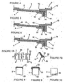
- Figure 1 shows a partial and fragmented perspective sectional view of a dismountable rim with an inner tyre and a tyre for such rim according to the invention.
- Figure 2 shows a detailed perspective view of the rim according to figure 1.
- Figure 3 shows a cross section of the rim and the tyre according to the invention.
- Figures 4-6 show cross sectional perspective views of the ancillary parts of three embodiments.
- Figure 7A shows a plan view of the rim without the tyre.
- Figure 7B shows a fragmented perspective view of the outer tyre.
- Figures 8-10 schematically show the relevant sectional views of three embodiments of the inner tyre.
- Figures 11-14 show the relevant sectional views of up to four embodiments of the inner tyre detailing its coupling to the rim.
- Figures 15-21 show the relevant fragmented perspective views of up to seven embodiments of the inner tyre.
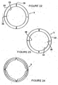
- Figures 22-24 show the relevant side views of three embodiments of the inner tyre.
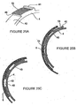
- Figures 25A-25C show relevant views of the rim detailing its coupling to the relevant inner tyre.
- As it can be observed in figures 1 and 2, the present invention is related to a demountable tire rim (1) with spare inner wheel (3), which is integrated by two complementary annular parts (4) (5) provided with threaded reciprocal coupling means (10).
- The body of the demountable tire rim (1) comprises two complementary annular parts (4)(5) which consist of a first part (4) and a second part (5). Both complementary annular parts (4) (5) are provided with each side holding rims (6)(13) for the tire (2).
- According to figure 7A, between the holding rim (6) or (13) and an adjacent rim (7a) a wedge is formed (7) for the tire (2) bead (51). The possibility that the adjacent rim (7a) has gearing means (43) with similar means (53) provided by the tire (2) bead (51) has been provided; this allows an integral assembly between the tire rim (1) and the tire (2) (See figure 7b).
- In the central part of the tire rim (1) there are assembly means for one or more spare wheels (3). These assembly means comprise a central depression (9). That may be even or grooved (17) limited by side edges (8) (12) and central rims (15), which are supported against said side edges (8) (12). When there are two or more spare wheels (3), separating rims (16) can be added (16). (See figures 1, 2, 4, 5 and 6).
- The two complementary annular parts (4) (5) have reciprocal coupling means based on threads (10). (See figures 1 and 2). In one case, the reciprocal coupling means consist of each continuous threads (10) formed at the above mentioned complementary annular parts (4)(5). In another case, the reciprocal coupling means consist of a plurality of threaded sectors (40) on the edge of the whole perimeter of both adjacent segments of the tire rim (1) which have, on one of their ends, an elevated part as a stop (41), inserted with sectors without thread (42), which surface is at a lower level in relation to the threaded sectors (40), these ones being different sectors, of the same width, so that they can be inserted to one another, to be fixed by means of threading spindrift movements. (See figures 25A, 25B and 25C).
- The reciprocal coupling means are complemented by means of interconnection and fixation means (19) of the complementary annular parts (4)(5). These interconnection and fixation means (19) comprise a plurality of equal and equally-spaced openings distributed on flanges placed on the perimeter of both edges, which, one opposite the other form passages for fixation screws or for bolts with lock-pin washer (See detail in figure 1 and figure 2).
- In figures 1, 4, 5 and 6, it can be seen that both complementary annular parts (4) (5) define a joint area (11) that may be even or with annular ledges. The annular ledges can be facing or insertable. In this joint area, there is an elastomeric joint (14) that may also be even or with annular ledges.
- Concerning the spare wheel (3), it can be grooved (23) (24) (25) or even (22) in one- piece, one- piece with recesses (29) on the even periphery (22), one-piece with recesses (30) on the inner edge (23) or either comprised by sectors related to an annular member which goes through them.
- Different examples of spare wheels (3) are illustrated in figures 7, 8, 9, 10, 11, 12, 13, 14, 15, 16, 17, 18, 19, 20, 21, 22, 23 and 24.
- With regard to the tire, in addition to the gearing means (53), it possesses a reinforcement annular member (52) arranged within the bead (51) (See figures 3 and 7B).
- In Figures 1 and 2, some inner ledges (50) of the above mentioned tire (2), can be seen to face and facilitate contact with the spare wheel (3) under flat tire running conditions.
- It is evident that when the present invention is put into practice, modifications may be made regarding certain construction and shape details, without departing from the basic principles, which are clearly encompassed in the following claims.
Claims (31)
- An assembly of a demountable tire rim, at least a spare inner wheel (3) and a tyre (2) forming a wheel for vehicles wherein the at least spare inner wheel has a diameter larger than said tire rim diameter and which acts with said tire when flat,:a) comprising a body of the tire rim (1) consisting of at least two complementary annular parts (4,5) of which both side parts provide each side holding rims (6-7a, 13-7a) of the tire;b) wherein said two complementary annular parts are provided with reciprocal coupling means (10);c) wherein assembly means (8, 9, 12, 17, 18) are conformed between the complementary annular parts for, at least, spare inner wheel; andd) wherein the tire (2) to be used with this tire rim and inner wheel shows modifications to adapt it to running under flat condition, said modifications consisting in inner ledges (50) formed on inner side of the tire tread and a bead (51) formed all around the perimeter in the both inner edges of the tire of its minor diameter,characterized in that
the reciprocal coupling means (10) consist of a plurality of each threaded sectors (40) on the edge of the whole perimeter of the two complementary annular parts (4, 5) of the tire rim, said plurality of each threaded sectors having on one of their ends, an elevated part (41) acting as stop,
said elevated part being suitable to be inserted with non threaded sectors (42) which surface is at a lower level relative to the threaded sectors, these different sectors being of the same width, so that they may be inserted to one another to be fixed by means of threading spindrift movements. - An assembly according to claim 1 wherein the complementary annular parts (4, 5) having further contact and tightness surfaces (11) cooperating with the reciprocal coupling means (10).
- An assembly according to claim 2 wherein the contact and tightness surfaces (11) are provided with a plurality of concentric annular ledges which have a reciprocal insertion arrangement to one another.
- An assembly according to claims 2-3 wherein between the opposite contact and tightness surfaces (11), is provided a laterally flat annular elastomeric joint which side surfaces are even.
- An assembly according to claims 2-3 wherein between the opposite contact and tightness surfaces (11), is provided a laterally flat annular elastomeric joint with a plurality of concentric annular edges on both side surfaces.
- An assembly according to any of preceding claims wherein the reciprocal coupling means (10) are complemented by interconnection and fixation means (19-19).
- An assembly according to claim 6 wherein the interconnection and fixation means (19-19) between the complementary annular parts (4, 5) consist of a plurality of sets of equal and equally-spaced openings distributed on flanges (20) placed at the perimeter of both edges, which faced to each other form passages for fixation screws (19).
- An assembly according to claim 6 wherein the interconnection and fixation means (19) between the complementary annular parts (4, 5) consist of a plurality of sets of a equal and equally-spaced openings distributed on flanges (20) placed at the perimeter of both edges, which faced to each other form passages for lock-pin bolts (19).
- An assembly according to claim 1 wherein the assembly means for the spare inner wheel consist of an annular depression (9) which side edges (8, 12) are provided by both complementary annular parts (4, 5).
- An assembly according to claim 9 wherein the annular depression (9) consists of a sliding and slipping track for the spare inner wheel (3).
- An assembly according to claims 9-10 wherein the annular depression (9) presents annular grooves (17) which decrease contact and friction surface with the spare inner wheel.
- An assembly according to claims 1 and 9 wherein the assembly means for the spare inner wheel (3) further comprising each side holding elastic rims (15) of said spare inner wheel and said side holding rims are arranged against the side edges (8, 12) provided by both complementary annular parts (4, 5), overrunning their height.
- An assembly according to claim 1 wherein comprises assembly means for more than one spare inner wheel (3), which means consist of an annular depression (9), divided in, at least, two sectors, by means of, at least, an intermediate elastic rim (16).
- An assembly according to claim 1 wherein the assembly means for the spare inner wheel (3) comprise the annular depression (9) and side retention means (18) of said inner wheel.
- An assembly according to claim 14 wherein the spare inner wheel (3) forms cooperation means (26) with the retention means (18).
- An assembly according to claim 1 which comprises bearing means which as bearing rollers (27) are inserted between the spare inner wheel (3) and the bottom of the annular depression (9).
- An assembly according to claim 1 wherein the spare inner wheel (3) is made of a single material.
- An assembly according to claim 1 wherein the spare inner wheel (3) consisting of a plurality of segments mutually related by strong and flexible joining means.
- An assembly according to claim 1 wherein the spare inner wheel (3) is made of elastomeric material.
- An assembly according to claim 1 the inner wheel (3) is made of plastic material.
- An assembly according to claim 1 wherein the spare inner wheel (3) is made of a light metal.
- An assembly to claim 1 wherein the spare inner wheel (3) is made of synthetic fibers and a material which compacts them.
- An assembly according to claim 1 wherein the spare inner wheel (3) has a structural reinforcement inner core (33).
- An assembly according to claim 1 wherein the spare inner wheel (3) is provided with a metal coating (31) on its major surface diameter provided with an outer layer (32) consisting of polytetrafluoroethylene polymer (PTFE).
- An assembly according to claim 1 wherein the spare inner wheel (3) is provided with flexibilizing means consisting of a plurality of narrowing (29-30) of its cross section.
- An assembly according to claim 1 wherein the spare inner wheel (3) forms recesses and ledges (24) on its base (23) which diminish its contact with the bottom of the annular depression (9).
- An assembly according to claim 1 wherein the spare inner wheel (3) forms recesses and ledges (23, 25) on its periphery which diminish its contact with the inner surface (50) of the tire tread.
- An assembly according to claim 1 wherein the spare inner wheels is crossed by a plurality of cross section openings (28) as easing and elasticity means.
- An assembly according to claim 1 wherein on the outer surface of each lateral segment (13) of the tire rim, there are at least two blind holes (21) placed at the same radius height, equally-spaced separated to each other, as a means to modify on them, elements which facilitate threading and unthreading movements of the complementary annular parts (4, 5) of the tire rim to each other.
- An assembly according to claim 1 wherein the complementary annular parts (4, 5) of the tire rim have all around the outer perimeter of the lip of the annular ledge and its adjacent parts, next to both side rims, a plurality of recesses and ledges (43) mutually equal and regularly spaced as a means to limit rotation of the tire (2) on the tire rim (1) upon running under flat condition.
- An assembly according to claims 1 and 30 wherein the tire (2) presents all around of the perimeter of both inner edges of its minor diameter, a plurality of recesses and ledges (53) with the same manner and distribution of those (43) found on the tire rim (1).
Applications Claiming Priority (2)
| Application Number | Priority Date | Filing Date | Title |
|---|---|---|---|
| ARP030103519A AR041409A1 (en) | 2003-09-26 | 2003-09-26 | DISASSEMBLY RIM WITH EMERGENCY AND TIRE INNER WHEEL FOR THE RIM |
| PCT/ES2004/000411 WO2005030505A1 (en) | 2003-09-26 | 2004-09-20 | Dismantlable rim comprising inner emergency wheel, and tyre for same |
Publications (2)
| Publication Number | Publication Date |
|---|---|
| EP1671815A1 EP1671815A1 (en) | 2006-06-21 |
| EP1671815B1 true EP1671815B1 (en) | 2007-11-07 |
Family
ID=36353847
Family Applications (1)
| Application Number | Title | Priority Date | Filing Date |
|---|---|---|---|
| EP04766949A Expired - Lifetime EP1671815B1 (en) | 2003-09-26 | 2004-09-20 | Dismantlable rim comprising inner emergency wheel, and tyre for same |
Country Status (7)
| Country | Link |
|---|---|
| US (1) | US7258403B2 (en) |
| EP (1) | EP1671815B1 (en) |
| AR (1) | AR041409A1 (en) |
| AT (1) | ATE377515T1 (en) |
| DE (1) | DE602004009951T2 (en) |
| ES (1) | ES2293330T3 (en) |
| WO (1) | WO2005030505A1 (en) |
Families Citing this family (14)
| Publication number | Priority date | Publication date | Assignee | Title |
|---|---|---|---|---|
| CN100450798C (en) * | 2006-03-16 | 2009-01-14 | 梁檬 | Safety device of vehicle tyre |
| JP4551422B2 (en) * | 2007-05-10 | 2010-09-29 | 本田技研工業株式会社 | Vehicle wheel |
| US20110221262A1 (en) * | 2008-07-24 | 2011-09-15 | Stuck Larry W | Runflat System with Interconnected Sectors |
| US20120104836A1 (en) * | 2010-10-31 | 2012-05-03 | Liao Ho-Yo | Structure of fast-screwed two-piece type wheel rim |
| EP2682287A1 (en) * | 2012-07-03 | 2014-01-08 | Europlast-Nycast GmbH | Tensionable runflat insert |
| EP2682288A1 (en) * | 2012-07-03 | 2014-01-08 | Europlast-Nycast GmbH | Motor vehicle wheel |
| DE102013217919A1 (en) | 2013-09-09 | 2015-03-12 | Fraunhofer-Gesellschaft zur Förderung der angewandten Forschung e.V. | Wheel hub, in particular aircraft hub |
| DE102014218105A1 (en) | 2014-09-10 | 2016-03-10 | Continental Reifen Deutschland Gmbh | vehicle |
| CN105667224A (en) * | 2016-04-11 | 2016-06-15 | 南京工程学院 | Slide rail type inner supporting device for automobile safety tire and assembly method |
| CN107914523A (en) * | 2016-10-10 | 2018-04-17 | 罗天珍 | The wheel of construction wheel hub is lacked with raised spiral or depression ring |
| EP3661768A4 (en) * | 2017-08-03 | 2021-04-07 | Hutchinson Industries, Inc. | Run flat system including a continuous elastomeric cap member |
| EP3599106B1 (en) | 2018-07-24 | 2024-04-03 | Marc-Ingegno di Marchini Alberto & C. S.a.s. | Assembly process of a vehicle wheel |
| AU2020363353B2 (en) * | 2019-10-08 | 2023-09-14 | Gacw Incorporated | Off-highway vehicle including frame coupled gas spring wheel assemblies |
| KR20220080148A (en) | 2019-10-10 | 2022-06-14 | 허친슨 에스.에이. | threaded wheel rims |
Family Cites Families (26)
| Publication number | Priority date | Publication date | Assignee | Title |
|---|---|---|---|---|
| US1433279A (en) * | 1922-10-24 | howell | ||
| US906404A (en) * | 1907-11-07 | 1908-12-08 | Augustus D Foucart | Elastic-tire wheel. |
| US2040645A (en) * | 1934-07-27 | 1936-05-12 | Fredrick S Dickinson | Noncollapsible tire |
| US2105317A (en) * | 1934-11-19 | 1938-01-11 | Bendix Prod Corp | Wheel |
| US2566663A (en) * | 1947-12-11 | 1951-09-04 | Goodrich Co B F | Forged wheel |
| US2496256A (en) * | 1948-03-09 | 1950-02-07 | Cecil E Bassett | Separable rim |
| DE1081779B (en) * | 1955-02-16 | 1960-05-12 | Continental Gummi Werke Ag | Toroidal hollow body made of rubber for air suspension, especially on vehicles |
| BE556144A (en) * | 1956-03-27 | |||
| US2990869A (en) * | 1959-01-26 | 1961-07-04 | Joseph L Riley | Pneumatic tires |
| US3037815A (en) * | 1959-06-15 | 1962-06-05 | Kelsey Hayes Co | Variable tread wheel |
| GB1439331A (en) * | 1972-09-08 | 1976-06-16 | Dunlop Ltd | Vehicle wheels |
| GB1522028A (en) * | 1975-09-26 | 1978-08-23 | Dunlop Ltd | Safety tyre and wheel rim assembly |
| US4015652A (en) * | 1975-11-12 | 1977-04-05 | The Goodyear Tire & Rubber Company | Tire and rim assembly |
| US4163466A (en) * | 1976-06-14 | 1979-08-07 | The Goodyear Tire & Rubber Company | Tubeless tire, safety support and rim assembly |
| AT365127B (en) * | 1979-09-03 | 1981-12-10 | Bbs Kraftfahrzeugtechnik | RIM FOR A MOTORCYCLE WHEEL |
| JPS5787705A (en) * | 1980-11-22 | 1982-06-01 | Honda Motor Co Ltd | Tire wheel structure |
| US4424842A (en) * | 1981-06-01 | 1984-01-10 | Trebaol Francois P | Vehicle wheel having safety tread |
| US4481997A (en) * | 1981-08-17 | 1984-11-13 | Motor Wheel Corporation | Tire and rim combination with safety insert |
| US4573509A (en) * | 1983-06-24 | 1986-03-04 | The Goodyear Tire & Rubber Company | Run flat device |
| DE8405217U1 (en) * | 1984-02-21 | 1985-05-30 | Uniroyal Englebert Reifen GmbH, 5100 Aachen | VEHICLE WHEEL |
| US4989657A (en) * | 1985-04-08 | 1991-02-05 | Center Line Tool Co., Inc. | Modular vehicle wheel |
| US5000241A (en) * | 1989-05-09 | 1991-03-19 | Patecell Theodore C | Unitary bead-lock and run-flat roller support ring for pneumatic tires on two-part wheels |
| US5022450A (en) * | 1989-11-06 | 1991-06-11 | Motor Wheel Corporation | Safety tire and take-apart wheel construction |
| JP3565965B2 (en) * | 1995-12-18 | 2004-09-15 | 本田技研工業株式会社 | Tube tires |
| US6814114B2 (en) * | 2001-11-26 | 2004-11-09 | Michelin Recherche Et Technique S.A. | Tire to rim rotation limiter for a run-flat assembly |
| AR033628A1 (en) * | 2002-05-06 | 2003-12-26 | Jose Santiago Rolla | RIM WITH GROOVED EMERGENCY AND PNEUMATIC INTERIOR SUPPORT FOR THE RIM |
-
2003
- 2003-09-26 AR ARP030103519A patent/AR041409A1/en unknown
-
2004
- 2004-01-05 US US10/751,707 patent/US7258403B2/en not_active Expired - Fee Related
- 2004-09-20 AT AT04766949T patent/ATE377515T1/en not_active IP Right Cessation
- 2004-09-20 DE DE602004009951T patent/DE602004009951T2/en not_active Expired - Fee Related
- 2004-09-20 ES ES04766949T patent/ES2293330T3/en not_active Expired - Lifetime
- 2004-09-20 EP EP04766949A patent/EP1671815B1/en not_active Expired - Lifetime
- 2004-09-20 WO PCT/ES2004/000411 patent/WO2005030505A1/en active IP Right Grant
Also Published As
| Publication number | Publication date |
|---|---|
| DE602004009951T2 (en) | 2008-05-15 |
| ATE377515T1 (en) | 2007-11-15 |
| ES2293330T3 (en) | 2008-03-16 |
| EP1671815A1 (en) | 2006-06-21 |
| US7258403B2 (en) | 2007-08-21 |
| US20050067079A1 (en) | 2005-03-31 |
| DE602004009951D1 (en) | 2007-12-20 |
| WO2005030505A1 (en) | 2005-04-07 |
| AR041409A1 (en) | 2005-05-18 |
Similar Documents
| Publication | Publication Date | Title |
|---|---|---|
| EP1671815B1 (en) | Dismantlable rim comprising inner emergency wheel, and tyre for same | |
| CA1193950A (en) | Safety liner for tires | |
| US10525776B2 (en) | Airless tire | |
| EP1094957A1 (en) | Vehicle wheel with a run flat support body | |
| US4573509A (en) | Run flat device | |
| EP3558694B1 (en) | Non-pneumatic wheel and hub | |
| US4480670A (en) | Track belt assembly | |
| US20240034095A1 (en) | Non-pneumatic tire with web having variable thickness | |
| CA1122892A (en) | Pneumatic truck tire | |
| EP0158039A1 (en) | Vehicle wheel pneumatic tyre with security support | |
| EP2585319B1 (en) | Multi-piece run-flat insert | |
| DE2922985C2 (en) | ||
| EP0103346B1 (en) | Tyre bead reinforcement | |
| EP0708713A1 (en) | Wheel assembly | |
| RU2441767C1 (en) | Studded tire | |
| DE3321978C2 (en) | ||
| EP0130136B1 (en) | Run flat device | |
| NZ242791A (en) | Car tyre traction increasing envelope | |
| US4270592A (en) | Unitary run-flat systems for inflatable tires and lock means | |
| EP0125640B1 (en) | Solid tyres for vehicle wheels or the like | |
| EP0881105A3 (en) | Vehicle pneumatic tyre | |
| CA1086202A (en) | Deflated tire annular support | |
| GB1587963A (en) | Pneumatic tyres | |
| DE3704798A1 (en) | VEHICLE WHEEL | |
| WO2008104730A1 (en) | Improved run-flat device |
Legal Events
| Date | Code | Title | Description |
|---|---|---|---|
| PUAI | Public reference made under article 153(3) epc to a published international application that has entered the european phase |
Free format text: ORIGINAL CODE: 0009012 |
|
| 17P | Request for examination filed |
Effective date: 20060412 |
|
| AK | Designated contracting states |
Kind code of ref document: A1 Designated state(s): AT BE BG CH CY CZ DE DK EE ES FI FR GB GR HU IE IT LI LU MC NL PL PT RO SE SI SK TR |
|
| DAX | Request for extension of the european patent (deleted) | ||
| GRAP | Despatch of communication of intention to grant a patent |
Free format text: ORIGINAL CODE: EPIDOSNIGR1 |
|
| GRAS | Grant fee paid |
Free format text: ORIGINAL CODE: EPIDOSNIGR3 |
|
| GRAA | (expected) grant |
Free format text: ORIGINAL CODE: 0009210 |
|
| AK | Designated contracting states |
Kind code of ref document: B1 Designated state(s): AT BE BG CH CY CZ DE DK EE ES FI FR GB GR HU IE IT LI LU MC NL PL PT RO SE SI SK TR |
|
| REG | Reference to a national code |
Ref country code: GB Ref legal event code: FG4D |
|
| REG | Reference to a national code |
Ref country code: IE Ref legal event code: FG4D |
|
| REG | Reference to a national code |
Ref country code: CH Ref legal event code: EP |
|
| REF | Corresponds to: |
Ref document number: 602004009951 Country of ref document: DE Date of ref document: 20071220 Kind code of ref document: P |
|
| REG | Reference to a national code |
Ref country code: ES Ref legal event code: FG2A Ref document number: 2293330 Country of ref document: ES Kind code of ref document: T3 |
|
| PG25 | Lapsed in a contracting state [announced via postgrant information from national office to epo] |
Ref country code: CH Free format text: LAPSE BECAUSE OF FAILURE TO SUBMIT A TRANSLATION OF THE DESCRIPTION OR TO PAY THE FEE WITHIN THE PRESCRIBED TIME-LIMIT Effective date: 20071107 Ref country code: LI Free format text: LAPSE BECAUSE OF FAILURE TO SUBMIT A TRANSLATION OF THE DESCRIPTION OR TO PAY THE FEE WITHIN THE PRESCRIBED TIME-LIMIT Effective date: 20071107 Ref country code: NL Free format text: LAPSE BECAUSE OF FAILURE TO SUBMIT A TRANSLATION OF THE DESCRIPTION OR TO PAY THE FEE WITHIN THE PRESCRIBED TIME-LIMIT Effective date: 20071107 Ref country code: SE Free format text: LAPSE BECAUSE OF FAILURE TO SUBMIT A TRANSLATION OF THE DESCRIPTION OR TO PAY THE FEE WITHIN THE PRESCRIBED TIME-LIMIT Effective date: 20080207 |
|
| NLV1 | Nl: lapsed or annulled due to failure to fulfill the requirements of art. 29p and 29m of the patents act | ||
| ET | Fr: translation filed | ||
| PG25 | Lapsed in a contracting state [announced via postgrant information from national office to epo] |
Ref country code: BG Free format text: LAPSE BECAUSE OF FAILURE TO SUBMIT A TRANSLATION OF THE DESCRIPTION OR TO PAY THE FEE WITHIN THE PRESCRIBED TIME-LIMIT Effective date: 20080207 Ref country code: PL Free format text: LAPSE BECAUSE OF FAILURE TO SUBMIT A TRANSLATION OF THE DESCRIPTION OR TO PAY THE FEE WITHIN THE PRESCRIBED TIME-LIMIT Effective date: 20071107 Ref country code: SI Free format text: LAPSE BECAUSE OF FAILURE TO SUBMIT A TRANSLATION OF THE DESCRIPTION OR TO PAY THE FEE WITHIN THE PRESCRIBED TIME-LIMIT Effective date: 20071107 |
|
| REG | Reference to a national code |
Ref country code: CH Ref legal event code: PL |
|
| PG25 | Lapsed in a contracting state [announced via postgrant information from national office to epo] |
Ref country code: AT Free format text: LAPSE BECAUSE OF FAILURE TO SUBMIT A TRANSLATION OF THE DESCRIPTION OR TO PAY THE FEE WITHIN THE PRESCRIBED TIME-LIMIT Effective date: 20071107 |
|
| PG25 | Lapsed in a contracting state [announced via postgrant information from national office to epo] |
Ref country code: DK Free format text: LAPSE BECAUSE OF FAILURE TO SUBMIT A TRANSLATION OF THE DESCRIPTION OR TO PAY THE FEE WITHIN THE PRESCRIBED TIME-LIMIT Effective date: 20071107 Ref country code: CZ Free format text: LAPSE BECAUSE OF FAILURE TO SUBMIT A TRANSLATION OF THE DESCRIPTION OR TO PAY THE FEE WITHIN THE PRESCRIBED TIME-LIMIT Effective date: 20071107 |
|
| PG25 | Lapsed in a contracting state [announced via postgrant information from national office to epo] |
Ref country code: SK Free format text: LAPSE BECAUSE OF FAILURE TO SUBMIT A TRANSLATION OF THE DESCRIPTION OR TO PAY THE FEE WITHIN THE PRESCRIBED TIME-LIMIT Effective date: 20071107 Ref country code: BE Free format text: LAPSE BECAUSE OF FAILURE TO SUBMIT A TRANSLATION OF THE DESCRIPTION OR TO PAY THE FEE WITHIN THE PRESCRIBED TIME-LIMIT Effective date: 20071107 Ref country code: RO Free format text: LAPSE BECAUSE OF FAILURE TO SUBMIT A TRANSLATION OF THE DESCRIPTION OR TO PAY THE FEE WITHIN THE PRESCRIBED TIME-LIMIT Effective date: 20071107 |
|
| PLBE | No opposition filed within time limit |
Free format text: ORIGINAL CODE: 0009261 |
|
| STAA | Information on the status of an ep patent application or granted ep patent |
Free format text: STATUS: NO OPPOSITION FILED WITHIN TIME LIMIT |
|
| PG25 | Lapsed in a contracting state [announced via postgrant information from national office to epo] |
Ref country code: PT Free format text: LAPSE BECAUSE OF FAILURE TO SUBMIT A TRANSLATION OF THE DESCRIPTION OR TO PAY THE FEE WITHIN THE PRESCRIBED TIME-LIMIT Effective date: 20080407 |
|
| 26N | No opposition filed |
Effective date: 20080808 |
|
| PGFP | Annual fee paid to national office [announced via postgrant information from national office to epo] |
Ref country code: ES Payment date: 20080916 Year of fee payment: 5 |
|
| PGFP | Annual fee paid to national office [announced via postgrant information from national office to epo] |
Ref country code: IT Payment date: 20080916 Year of fee payment: 5 |
|
| PGFP | Annual fee paid to national office [announced via postgrant information from national office to epo] |
Ref country code: GB Payment date: 20080916 Year of fee payment: 5 |
|
| PG25 | Lapsed in a contracting state [announced via postgrant information from national office to epo] |
Ref country code: GR Free format text: LAPSE BECAUSE OF FAILURE TO SUBMIT A TRANSLATION OF THE DESCRIPTION OR TO PAY THE FEE WITHIN THE PRESCRIBED TIME-LIMIT Effective date: 20080208 |
|
| PGFP | Annual fee paid to national office [announced via postgrant information from national office to epo] |
Ref country code: DE Payment date: 20081127 Year of fee payment: 5 |
|
| PG25 | Lapsed in a contracting state [announced via postgrant information from national office to epo] |
Ref country code: FI Free format text: LAPSE BECAUSE OF FAILURE TO SUBMIT A TRANSLATION OF THE DESCRIPTION OR TO PAY THE FEE WITHIN THE PRESCRIBED TIME-LIMIT Effective date: 20071107 |
|
| PG25 | Lapsed in a contracting state [announced via postgrant information from national office to epo] |
Ref country code: EE Free format text: LAPSE BECAUSE OF FAILURE TO SUBMIT A TRANSLATION OF THE DESCRIPTION OR TO PAY THE FEE WITHIN THE PRESCRIBED TIME-LIMIT Effective date: 20071107 Ref country code: MC Free format text: LAPSE BECAUSE OF NON-PAYMENT OF DUE FEES Effective date: 20080930 |
|
| PGFP | Annual fee paid to national office [announced via postgrant information from national office to epo] |
Ref country code: FR Payment date: 20080930 Year of fee payment: 5 |
|
| PG25 | Lapsed in a contracting state [announced via postgrant information from national office to epo] |
Ref country code: IE Free format text: LAPSE BECAUSE OF NON-PAYMENT OF DUE FEES Effective date: 20080922 Ref country code: CY Free format text: LAPSE BECAUSE OF FAILURE TO SUBMIT A TRANSLATION OF THE DESCRIPTION OR TO PAY THE FEE WITHIN THE PRESCRIBED TIME-LIMIT Effective date: 20071107 |
|
| GBPC | Gb: european patent ceased through non-payment of renewal fee |
Effective date: 20090920 |
|
| REG | Reference to a national code |
Ref country code: FR Ref legal event code: ST Effective date: 20100531 |
|
| PG25 | Lapsed in a contracting state [announced via postgrant information from national office to epo] |
Ref country code: FR Free format text: LAPSE BECAUSE OF NON-PAYMENT OF DUE FEES Effective date: 20090930 Ref country code: DE Free format text: LAPSE BECAUSE OF NON-PAYMENT OF DUE FEES Effective date: 20100401 Ref country code: HU Free format text: LAPSE BECAUSE OF FAILURE TO SUBMIT A TRANSLATION OF THE DESCRIPTION OR TO PAY THE FEE WITHIN THE PRESCRIBED TIME-LIMIT Effective date: 20080508 Ref country code: LU Free format text: LAPSE BECAUSE OF NON-PAYMENT OF DUE FEES Effective date: 20080920 |
|
| PG25 | Lapsed in a contracting state [announced via postgrant information from national office to epo] |
Ref country code: TR Free format text: LAPSE BECAUSE OF FAILURE TO SUBMIT A TRANSLATION OF THE DESCRIPTION OR TO PAY THE FEE WITHIN THE PRESCRIBED TIME-LIMIT Effective date: 20071107 |
|
| PG25 | Lapsed in a contracting state [announced via postgrant information from national office to epo] |
Ref country code: GB Free format text: LAPSE BECAUSE OF NON-PAYMENT OF DUE FEES Effective date: 20090920 |
|
| PG25 | Lapsed in a contracting state [announced via postgrant information from national office to epo] |
Ref country code: IT Free format text: LAPSE BECAUSE OF NON-PAYMENT OF DUE FEES Effective date: 20090920 |
|
| REG | Reference to a national code |
Ref country code: ES Ref legal event code: FD2A Effective date: 20110711 |
|
| PG25 | Lapsed in a contracting state [announced via postgrant information from national office to epo] |
Ref country code: ES Free format text: LAPSE BECAUSE OF NON-PAYMENT OF DUE FEES Effective date: 20110629 |
|
| PG25 | Lapsed in a contracting state [announced via postgrant information from national office to epo] |
Ref country code: ES Free format text: LAPSE BECAUSE OF NON-PAYMENT OF DUE FEES Effective date: 20090921 |