EP1671799A2 - Defect detection device of a printer head and associated method - Google Patents
Defect detection device of a printer head and associated method Download PDFInfo
- Publication number
- EP1671799A2 EP1671799A2 EP05257654A EP05257654A EP1671799A2 EP 1671799 A2 EP1671799 A2 EP 1671799A2 EP 05257654 A EP05257654 A EP 05257654A EP 05257654 A EP05257654 A EP 05257654A EP 1671799 A2 EP1671799 A2 EP 1671799A2
- Authority
- EP
- European Patent Office
- Prior art keywords
- vibration signal
- vibration
- printer head
- actuator
- kth
- Prior art date
- Legal status (The legal status is an assumption and is not a legal conclusion. Google has not performed a legal analysis and makes no representation as to the accuracy of the status listed.)
- Granted
Links
Images



Classifications
-
- B—PERFORMING OPERATIONS; TRANSPORTING
- B41—PRINTING; LINING MACHINES; TYPEWRITERS; STAMPS
- B41J—TYPEWRITERS; SELECTIVE PRINTING MECHANISMS, i.e. MECHANISMS PRINTING OTHERWISE THAN FROM A FORME; CORRECTION OF TYPOGRAPHICAL ERRORS
- B41J2/00—Typewriters or selective printing mechanisms characterised by the printing or marking process for which they are designed
- B41J2/005—Typewriters or selective printing mechanisms characterised by the printing or marking process for which they are designed characterised by bringing liquid or particles selectively into contact with a printing material
- B41J2/01—Ink jet
- B41J2/135—Nozzles
- B41J2/165—Prevention or detection of nozzle clogging, e.g. cleaning, capping or moistening for nozzles
- B41J2/16579—Detection means therefor, e.g. for nozzle clogging
-
- B—PERFORMING OPERATIONS; TRANSPORTING
- B41—PRINTING; LINING MACHINES; TYPEWRITERS; STAMPS
- B41J—TYPEWRITERS; SELECTIVE PRINTING MECHANISMS, i.e. MECHANISMS PRINTING OTHERWISE THAN FROM A FORME; CORRECTION OF TYPOGRAPHICAL ERRORS
- B41J2/00—Typewriters or selective printing mechanisms characterised by the printing or marking process for which they are designed
- B41J2/005—Typewriters or selective printing mechanisms characterised by the printing or marking process for which they are designed characterised by bringing liquid or particles selectively into contact with a printing material
- B41J2/01—Ink jet
- B41J2/015—Ink jet characterised by the jet generation process
- B41J2/02—Ink jet characterised by the jet generation process generating a continuous ink jet
- B41J2/025—Ink jet characterised by the jet generation process generating a continuous ink jet by vibration
-
- B—PERFORMING OPERATIONS; TRANSPORTING
- B41—PRINTING; LINING MACHINES; TYPEWRITERS; STAMPS
- B41J—TYPEWRITERS; SELECTIVE PRINTING MECHANISMS, i.e. MECHANISMS PRINTING OTHERWISE THAN FROM A FORME; CORRECTION OF TYPOGRAPHICAL ERRORS
- B41J2/00—Typewriters or selective printing mechanisms characterised by the printing or marking process for which they are designed
- B41J2/005—Typewriters or selective printing mechanisms characterised by the printing or marking process for which they are designed characterised by bringing liquid or particles selectively into contact with a printing material
- B41J2/01—Ink jet
- B41J2/015—Ink jet characterised by the jet generation process
- B41J2/04—Ink jet characterised by the jet generation process generating single droplets or particles on demand
- B41J2/045—Ink jet characterised by the jet generation process generating single droplets or particles on demand by pressure, e.g. electromechanical transducers
- B41J2/04501—Control methods or devices therefor, e.g. driver circuits, control circuits
- B41J2/0451—Control methods or devices therefor, e.g. driver circuits, control circuits for detecting failure, e.g. clogging, malfunctioning actuator
-
- B—PERFORMING OPERATIONS; TRANSPORTING
- B41—PRINTING; LINING MACHINES; TYPEWRITERS; STAMPS
- B41J—TYPEWRITERS; SELECTIVE PRINTING MECHANISMS, i.e. MECHANISMS PRINTING OTHERWISE THAN FROM A FORME; CORRECTION OF TYPOGRAPHICAL ERRORS
- B41J2/00—Typewriters or selective printing mechanisms characterised by the printing or marking process for which they are designed
- B41J2/005—Typewriters or selective printing mechanisms characterised by the printing or marking process for which they are designed characterised by bringing liquid or particles selectively into contact with a printing material
- B41J2/01—Ink jet
- B41J2/015—Ink jet characterised by the jet generation process
- B41J2/04—Ink jet characterised by the jet generation process generating single droplets or particles on demand
- B41J2/045—Ink jet characterised by the jet generation process generating single droplets or particles on demand by pressure, e.g. electromechanical transducers
- B41J2/04501—Control methods or devices therefor, e.g. driver circuits, control circuits
- B41J2/04581—Control methods or devices therefor, e.g. driver circuits, control circuits controlling heads based on piezoelectric elements
-
- B—PERFORMING OPERATIONS; TRANSPORTING
- B41—PRINTING; LINING MACHINES; TYPEWRITERS; STAMPS
- B41J—TYPEWRITERS; SELECTIVE PRINTING MECHANISMS, i.e. MECHANISMS PRINTING OTHERWISE THAN FROM A FORME; CORRECTION OF TYPOGRAPHICAL ERRORS
- B41J2/00—Typewriters or selective printing mechanisms characterised by the printing or marking process for which they are designed
- B41J2/005—Typewriters or selective printing mechanisms characterised by the printing or marking process for which they are designed characterised by bringing liquid or particles selectively into contact with a printing material
- B41J2/01—Ink jet
- B41J2/015—Ink jet characterised by the jet generation process
- B41J2/04—Ink jet characterised by the jet generation process generating single droplets or particles on demand
- B41J2/045—Ink jet characterised by the jet generation process generating single droplets or particles on demand by pressure, e.g. electromechanical transducers
- B41J2/04501—Control methods or devices therefor, e.g. driver circuits, control circuits
- B41J2/04588—Control methods or devices therefor, e.g. driver circuits, control circuits using a specific waveform
-
- B—PERFORMING OPERATIONS; TRANSPORTING
- B41—PRINTING; LINING MACHINES; TYPEWRITERS; STAMPS
- B41J—TYPEWRITERS; SELECTIVE PRINTING MECHANISMS, i.e. MECHANISMS PRINTING OTHERWISE THAN FROM A FORME; CORRECTION OF TYPOGRAPHICAL ERRORS
- B41J2/00—Typewriters or selective printing mechanisms characterised by the printing or marking process for which they are designed
- B41J2/005—Typewriters or selective printing mechanisms characterised by the printing or marking process for which they are designed characterised by bringing liquid or particles selectively into contact with a printing material
- B41J2/01—Ink jet
- B41J2/07—Ink jet characterised by jet control
- B41J2/125—Sensors, e.g. deflection sensors
-
- B—PERFORMING OPERATIONS; TRANSPORTING
- B41—PRINTING; LINING MACHINES; TYPEWRITERS; STAMPS
- B41J—TYPEWRITERS; SELECTIVE PRINTING MECHANISMS, i.e. MECHANISMS PRINTING OTHERWISE THAN FROM A FORME; CORRECTION OF TYPOGRAPHICAL ERRORS
- B41J2/00—Typewriters or selective printing mechanisms characterised by the printing or marking process for which they are designed
- B41J2/005—Typewriters or selective printing mechanisms characterised by the printing or marking process for which they are designed characterised by bringing liquid or particles selectively into contact with a printing material
- B41J2/01—Ink jet
- B41J2/135—Nozzles
- B41J2/14—Structure thereof only for on-demand ink jet heads
- B41J2002/14354—Sensor in each pressure chamber
Definitions
- the present invention relates to a piezoelectric type inkjet printer head, and more particularly, to a defect detection device for detecting defects such as a crack or adhesion failure, etc. existing in a printer head and a method of detecting defect thereof.
- an inkjet printer is a device for printing an image of a predetermined color by ejecting droplets of ink for printing in a desirable position on a print sheet.
- ink ejection in the inkjet printer There are two types of ink ejection in the inkjet printer.
- One is a bubble jet type of an electro-thermal transducer which generates bubbles in ink by using a heat source and ejects ink by the force of generated bubbles.
- the other is a piezoelectric type of an electro-mechanical transducer which ejects ink by means of a volume change of ink due to transformation of a piezoelectric body.
- FIG. 1 is a diagram illustrating an embodiment of a conventional piezoelectric type of an inkjet printer head.
- FIG. 2 is a diagram illustrating in detail a portion 10 of the inkjet printer head shown in FIG. 1.
- a piezoelectric type of an inkjet print head comprise actuators 20, an upper plate 30, ink chambers 40, a middle plate 50, and a lower plate 60.
- the actuators 20 are provided on the upper plate 30. It have the structure in which a piezoelectric thin plates and electrodes are stacked to apply a voltage to the piezoelectric thin plates.
- the actuators 20 perform a function of transform the upper plate 30.
- the upper plate 30 is deformed by the actuators 20 and changes volumes of the ink chambers 40.
- the ink chambers 40 are filled with ink to be ejected. It generates a pressure change to eject or inject because their volume is changed by driving the actuators 20. Passages (not shown) for ejecting ink are provided in the middle plate 50. Nozzles (not shown) are provided in the lower plate 60.
- a conventional piezoelectric type of an inkjet printer head having such structure is operated as follows.
- a conventional piezoelectric type of an inkjet printer head has a high likelihood of a crack taking place at contact portions 70 of the upper plate 30 and the actuator 20.
- the upper plate 30 is relatively thin due to the existence of the ink chambers 40 in the contact portions 70 of the upper plate 30 and the actuator 20. Therefore, there is a high likelihood that a crack taking place at the contact portions 70 of the actuator 20 and the upper plate 30 compared to other portions.
- a defect detection device of a printer head comprising: first to Nth (N is a positive integer) actuators providing a driving force for ejecting ink into ink chambers; a vibration signal generator generating vibration signals for vibrating the first to Nth actuators; a first switch receiving the generated vibration signals and outputting the vibration signals to the Kth (K is any integer ranging from 1 to N) actuator among the first to Nth actuators; a second switch receiving vibration signals of one or more among the first to Nth actuators vibrating concurrently with the vibration of the Kth actuator and outputting the Lth vibration signal that corresponds to a vibration signal of the Lth actuator (L is any integer ranging from 1 to N) adjacent to the Kth actuator among the received vibration signals; and a defect detector comparing the Lth vibration signal output from the second switch with a specific vibration signal of the Lth actuator when there is no defect in a printer head and detecting defects in the printer head.
- a defect detection device of a printer head comprising: first to Nth (N is a positive integer) actuators providing a driving force for ejecting ink to ink chambers; a vibration signal generator generating vibration signals for vibrating the first to Nth actuators; a switch receiving the generated vibration signals and outputting the vibration signals to the Kth (K is any integer ranging from 1 to N) actuator among the first to Nth actuators; and a defect detector receiving the Kth vibration signal of the Kth actuator that is made to vibrate by the vibration signals, comparing the received Kth vibration signal with the specific vibration signal of the Kth actuator when there is no defect in the printer head, and detecting defects of the printer head.
- a method of detecting defects in a printer head comprising: generating vibration signals for vibrating first to Nth (N is one or more positive integer) actuators; receiving the generated vibration signals and outputting the vibration signals to the Kth (K is any integer ranging from 1 to N) actuator of the first to Nth actuators; receiving vibration signals of one or more of the first to Nth actuators vibrating concurrently with the vibration of the Kth actuator and outputting the Lth vibration signal that corresponds to a vibration signal of the Lth (L is any integer ranging from 1 to N) actuator adjacent to the Kth actuator, among the received vibration signals; and comparing the Lth vibration signal with the specific vibration signal of the Lth actuator when there is no defect in the printer head and detecting defects of the printer head.
- a method of detecting defects in a printer head comprising: generating vibration signals for vibrating first to Nth (N is one or more positive integer) actuators; receiving the generated vibration signals and outputting the vibration signals to the Kth (K is any integer ranging from 1 to N) actuator of the first to Nth actuators; receiving vibration signals of one or more of the first to Nth actuators vibrating concurrently with the vibration of the Kth actuator and outputting the L 1 th vibration signal that corresponds to a vibration signal of the Lth (L is any integer ranging from 1 to N) actuator adjacent to the Kth actuator, among the received vibration signals; generating the vibration signals again; receiving the generated vibration signals and outputting the vibration signals to the Mth (M is any integer ranging from 1 to N) actuator adjacent to the Lth actuator of the first to Nth actuators; receiving vibration signals of one or more of the first to Nth actuators vibrating concurrently with the vibration of the Mth actuator and outputting the L 2 th vibration signal that corresponds
- FIG. 7 is a block diagram of another embodiment for explaining a defect detection device of a printer head according to the present invention, where the defect detection device comprises a vibration signal generator 300, a switch 310, first to Nth actuators 320, an amplifier 330, and a defect detector 340.
- the defect detection device comprises a vibration signal generator 300, a switch 310, first to Nth actuators 320, an amplifier 330, and a defect detector 340.
- the Kth actuator is vibrated by received vibration signals and output the Kth vibration signal by vibrating the Kth actuator.
- FIG. 10 is a diagram illustrating a specific vibration signal detected from an actuator of a printer head having no defect and a vibration signal detected from an actuator of a printer head having defects.
- Graph 1 shown in FIG. 10 shows the specific vibration signal detected from the actuator of the printer head having no defect
- graph 2 shown in FIG. 10 shows that vibration signal detected from the actuator of the printer head having defects.
- vibration signals detected from the actuator have the same resonance frequency 677 kHz as on graph 1 shown in FIG. 10.
- vibration signals detected from the actuator are different from those of FIG. 10 as on graph 2 shown in FIG. 10.
- the reason that vibration signals are different is that vibration signals of the Kth actuator is not properly detected due to defects such as a crack or adhesion failure, etc. around the Kth actuator.
- vibration signals for vibrating the first to Nth (N is one or more positive integer) actuators is generated (operation 700). Specifically, in the present invention, sinusoidal waveforms are generated.
- the Kth actuator is vibrated by the received vibration signal.
- vibration signals of one or more of the first to Nth actuators vibrating concurrently with the vibration of the Kth actuator are received and the L 1 th vibration signal that corresponds to a vibration signal of the Lth (L is any integer ranging from 1 to N) actuator adjacent to the Kth actuator among the received vibration signals is output (operation 904).
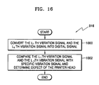
- FIG. 16 is a flowchart of an embodiment for explaining operation 916 shown in FIG. 15.
- the L 1 th vibration signal and the L 2 th vibration signal are converted into digital signals (operation 1000).
- the L 1 th vibration signal converted into a digital signal is compared with a specific vibration signal that is a digital signal
- the L 2 th vibration signal converted into a digital signal is compared with the specific vibration signal that is a digital signal, and defects in the printer head are determined.
- the defect detection device and the method of detecting defects in the printer head according to the present invention make it possible to easily determine the quality of the printer head at a low cost.
Landscapes
- Ink Jet (AREA)
- Particle Formation And Scattering Control In Inkjet Printers (AREA)
Abstract
Description
- The present invention relates to a piezoelectric type inkjet printer head, and more particularly, to a defect detection device for detecting defects such as a crack or adhesion failure, etc. existing in a printer head and a method of detecting defect thereof.
- In general, an inkjet printer is a device for printing an image of a predetermined color by ejecting droplets of ink for printing in a desirable position on a print sheet. There are two types of ink ejection in the inkjet printer. One is a bubble jet type of an electro-thermal transducer which generates bubbles in ink by using a heat source and ejects ink by the force of generated bubbles. The other is a piezoelectric type of an electro-mechanical transducer which ejects ink by means of a volume change of ink due to transformation of a piezoelectric body.
- FIG. 1 is a diagram illustrating an embodiment of a conventional piezoelectric type of an inkjet printer head. FIG. 2 is a diagram illustrating in detail a
portion 10 of the inkjet printer head shown in FIG. 1. As shown in FIG. 2, a piezoelectric type of an inkjet print head compriseactuators 20, anupper plate 30,ink chambers 40, amiddle plate 50, and alower plate 60. Theactuators 20 are provided on theupper plate 30. It have the structure in which a piezoelectric thin plates and electrodes are stacked to apply a voltage to the piezoelectric thin plates. Theactuators 20 perform a function of transform theupper plate 30. Theupper plate 30 is deformed by theactuators 20 and changes volumes of theink chambers 40. Theink chambers 40 are filled with ink to be ejected. It generates a pressure change to eject or inject because their volume is changed by driving theactuators 20. Passages (not shown) for ejecting ink are provided in themiddle plate 50. Nozzles (not shown) are provided in thelower plate 60. - A conventional piezoelectric type of an inkjet printer head having such structure is operated as follows.
- Volumes of the
ink chambers 40 decreases when theupper plate 30 is deformed by driving theactuators 20. Ink inside theink chambers 40 is ejected to the outside through nozzles of thelower plate 60 by a pressure change due to decreased volumes of theink chambers 40. Thereafter, the volumes of theink chambers 40 increases when theupper plate 30 return to an original shape by driving theactuators 20 and ink is again injected into theink chambers 40 by a pressure change due to increased volumes of theink chambers 40. - A conventional piezoelectric type of an inkjet printer head has a high likelihood of a crack taking place at
contact portions 70 of theupper plate 30 and theactuator 20. Theupper plate 30 is relatively thin due to the existence of theink chambers 40 in thecontact portions 70 of theupper plate 30 and theactuator 20. Therefore, there is a high likelihood that a crack taking place at thecontact portions 70 of theactuator 20 and theupper plate 30 compared to other portions. - Further, in a conventional piezoelectric type of an inkjet printer head, when adhesion between the
upper plate 30 and themiddle plate 50 is not properly made, as in shown in FIG. 2, anaperture 80 occurs at adhesion portions between theupper plate 30 and themiddle plate 50. Ifsuch aperture 80 occurs, ink stored in theink chambers 40 permeate theaperture 80. Therefore, it is impossible to correctly eject ink, depending on a pressure change in theink chambers 40. - According to an aspect of the present invention, there is provided a defect detection device of a printer head comprising: first to Nth (N is a positive integer) actuators providing a driving force for ejecting ink into ink chambers; a vibration signal generator generating vibration signals for vibrating the first to Nth actuators; a first switch receiving the generated vibration signals and outputting the vibration signals to the Kth (K is any integer ranging from 1 to N) actuator among the first to Nth actuators; a second switch receiving vibration signals of one or more among the first to Nth actuators vibrating concurrently with the vibration of the Kth actuator and outputting the Lth vibration signal that corresponds to a vibration signal of the Lth actuator (L is any integer ranging from 1 to N) adjacent to the Kth actuator among the received vibration signals; and a defect detector comparing the Lth vibration signal output from the second switch with a specific vibration signal of the Lth actuator when there is no defect in a printer head and detecting defects in the printer head.
- According to another aspect of the present invention, there is provided a defect detection device of a printer head comprising: first to Nth (N is a positive integer) actuators providing a driving force for ejecting ink to ink chambers; a vibration signal generator generating vibration signals for vibrating the first to Nth actuators; a switch receiving the generated vibration signals and outputting the vibration signals to the Kth (K is any integer ranging from 1 to N) actuator among the first to Nth actuators; and a defect detector receiving the Kth vibration signal of the Kth actuator that is made to vibrate by the vibration signals, comparing the received Kth vibration signal with the specific vibration signal of the Kth actuator when there is no defect in the printer head, and detecting defects of the printer head.
- According to a further aspect of the present invention, there is provided a method of detecting defects in a printer head comprising: generating vibration signals for vibrating first to Nth (N is one or more positive integer) actuators; receiving the generated vibration signals and outputting the vibration signals to the Kth (K is any integer ranging from 1 to N) actuator of the first to Nth actuators; receiving vibration signals of one or more of the first to Nth actuators vibrating concurrently with the vibration of the Kth actuator and outputting the Lth vibration signal that corresponds to a vibration signal of the Lth (L is any integer ranging from 1 to N) actuator adjacent to the Kth actuator, among the received vibration signals; and comparing the Lth vibration signal with the specific vibration signal of the Lth actuator when there is no defect in the printer head and detecting defects of the printer head.
- According to an even further aspect of the present invention, there is provided a method of detecting defects in a printer head comprising: generating vibration signals for vibrating first to Nth (N is one or more positive integer) actuators; receiving the generated vibration signals and outputting the vibration signals to the Kth (K is any integer ranging from 1 to N) actuator of the first to Nth actuators; and receiving the Kth vibration signal of the Kth actuator that is made to vibrate the vibration signals, comparing the received Kth vibration signal with the specific vibration signal of the Kth actuator when there is no defect in the printer head, and detecting defects of the printer head.
- According to a still further aspect of the present invention, there is provided a method of detecting defects in a printer head comprising: generating vibration signals for vibrating first to Nth (N is one or more positive integer) actuators; receiving the generated vibration signals and outputting the vibration signals to the Kth (K is any integer ranging from 1 to N) actuator of the first to Nth actuators; receiving vibration signals of one or more of the first to Nth actuators vibrating concurrently with the vibration of the Kth actuator and outputting the L1th vibration signal that corresponds to a vibration signal of the Lth (L is any integer ranging from 1 to N) actuator adjacent to the Kth actuator, among the received vibration signals; generating the vibration signals again; receiving the generated vibration signals and outputting the vibration signals to the Mth (M is any integer ranging from 1 to N) actuator adjacent to the Lth actuator of the first to Nth actuators; receiving vibration signals of one or more of the first to Nth actuators vibrating concurrently with the vibration of the Mth actuator and outputting the L2th vibration signal that corresponds to another vibration signal of the Lth actuator, among the received vibration signals; and comparing the L1th vibration signal with the specific vibration signal of the Lth actuator when there is no defect in the printer head, comparing the L2th vibration signal with the specific vibration signal, and detecting defects of the printer head.
- The present invention thus provides a defect detection device for detecting defects such as a crack or adhesion failure, etc. existing in the printer head.
- The present invention further provides a method of detecting defects in the printer head such as a crack or adhesion failure, etc. existing in the printer head.
- The above and other features and advantages of the present invention will become more apparent by describing in detail exemplary embodiments thereof with reference to the attached drawings in which:
- FIG. 1 is a diagram illustrating an embodiment of an inkjet printer head in a conventional piezoelectric method;
- FIG. 2 is a diagram illustrating in detail a part of the inkjet printer head shown in FIG. 1;
- FIG. 3 is a block diagram of an embodiment for explaining a defect detection device of a printer head according to the present invention;
- FIG. 4 is a diagram illustrating an embodiment of specific vibration signal detected from an actuator of a printer head having no defect and vibration signal detected from an actuator of a printer head having defects;
- FIG. 5 is a block diagram of an embodiment for explaining a defect detector shown in FIG. 3;
- FIG. 6 is a diagram illustrating another embodiment of specific vibration signal detected from an actuator of a printer head having no defect and vibration signal detected from an actuator of a printer head having defects;
- FIG. 7 is a block diagram of another embodiment for explaining a defect detection device of a printer head according to the present invention;
- FIG. 8 is a diagram illustrating physical characteristics of an actuator with an equivalent circuit;
- FIG. 9 is a block diagram of an embodiment for explaining a defect detector shown in FIG. 7;
- FIG. 10 is a diagram illustrating specific vibration signal detected from an actuator of a printer head having no defect and vibration signal detected from an actuator of a printer head having defects;
- FIG. 11 is a flowchart of an embodiment for explaining a method of detecting defects in the printer head according to the present invention;
- FIG. 12 is a flowchart of an embodiment for explaining
operation 508 shown in FIG. 11; - FIG. 13 is a flowchart of another embodiment for explaining a method of detecting defects in the printer head according to the present invention;
- FIG. 14 is a flowchart of an embodiment for explaining
operation 706 shown in FIG. 13; - FIG. 15 is a flowchart of another embodiment for explaining a method of detecting defects in the printer head according to the present invention; and
- FIG. 16 is a flowchart of an embodiment for explaining
operation 916 shown in FIG. 15. - The present invention will now be described more fully with reference to the accompanying drawings, in which exemplary embodiments of the present invention are shown.
- FIG. 3 is a block diagram of an embodiment for explaining a defect detection device of a printer head according to the present invention, where the defect detection device comprises a
vibration signal generator 100, afirst switch 110, first toNth actuators 120, asecond switch 130, aamplifier 140, and adefect detector 150. - The first to Nth (N is one or more positive integer)
actuators 120 provide a driving force for ejecting ink to ink chambers. The first toNth actuators 120 are situated in an upper part of the printer head and change volumes of the ink chambers (not shown). The first toNth actuators 120 allow ink to eject to the outside through nozzles from the ink chambers by changing volumes of the ink chambers. - The
vibration signal generator 100 generates vibration signals for vibrating the first toNth actuators 120 and outputs the generated vibration signals to thefirst switch 110. Thevibration signal generator 100 can generate waveforms of various kinds of vibration signals. Specifically, it generates sinusoidal waveforms in the present invention. The first toNth actuators 120 are vibrated by vibration signals. - The
first switch 110 receives the generated vibration signals and outputs vibration signals to the Kth (K is any integer ranging from 1 to N) actuator among the first toNth actuators 120. Thefirst switch 110 outputs vibration signals to the Kth actuator among the first toNth actuators 120 in order to check whether a crack or an aperture occurs around the Kth actuator,. - The Kth actuator is vibrated by the received vibration signals.
- The
second switch 130 receives vibration signals of one or more among the first to Nth actuators vibrating concurrently with vibrating of the Kth actuator and outputs the Lth vibration signal that corresponds to a vibration signal of the Lth (L is any integer ranging from 1 to N) actuator adjacent to the Kth actuator among the received vibration signals to theamplifier 140. Specifically, a vibration signal means a change of a maximum voltage depending on a frequency change measured from a vibrating actuator. When the actuator is vibrated, a voltage is generated by physical characteristics of the actuator. A maximum voltage change depending on a frequency change of vibration signals for such a generated voltage can be detected. Thesecond switch 130 receives such s maximum voltage change as vibration signals. - Actuators around the Kth actuator are also vibrated when the Kth actuator is vibrated by vibration signals generated from the
vibration signal generator 100. Thesecond switch 130 outputs the Lth vibration signal by vibration of the Lth actuator adjacent directly to the Kth actuator among the actuators around the Kth actuator, to theamplifier 140. - The
amplifier 140 amplifies the Lth vibration signal output from thesecond switch 130 and output the amplified Lth vibration signal to thedefect detector 150. - The
defect detector 150 compares the Lth vibration signal amplified from theamplifier 140 with a specific vibration signal of the Lth actuator when there is no defect in the printer head and detects defects in the printer head. The specific vibration signal means a maximum voltage change depending on a frequency change measured from the first toNth actuators 120 when defects such as a crack or adhesion failure and so on does not occur in the printer head having the first toNth actuators 120. Vibration signals corresponding to a maximum voltage change depending on a frequency change shows the same shape in all of the first toNth actuators 120 of the printer head having no defect. That is, vibration signals of the first toNth actuators 120 of the printer head having no defect show that frequency, that is, resonance frequency is the same at the level of the highest value of maximum voltage change. - FIG. 4 is a diagram illustrating an embodiment of a specific vibration signal detected from the actuator of the printer head having no defect and a vibration signal detected from the actuator of the printer head having defect.
Graph ① shown in FIG. 4 shows the specific vibration signal detected from the actuator of the printer head having no defect and graph ② shown in FIG. 4 shows the vibration signal detected from the actuator of the printer head having defect. When there is no defect in the printer head, the vibration signal detected from the actuator have thesame resonance frequency 690 kHz as on thegraph ① shown in FIG. 4. However, when there are defects in the printer head, vibration signals detected from the actuator haveresonance frequency 730 kHz different from theresonance frequency 690 kHz of thegraph ① shown in FIG. 4 as on the graph ② shown in FIG. 4. - The reason that the resonance frequency is different is that the vibration of the Kth actuator is not properly transmitted to the Lth actuator due to defects such as a crack or adhesion failure, etc. between the Kth actuator and the Lth actuator.
- FIG. 5 is a block diagram of an embodiment for explaining a
defect detector 150 shown in FIG. 3, where thedefect detector 150 comprises an analog-digital converter 200 and adefect determination unit 220. - The analog-
digital converter 200 converts the Lth vibration signal into a digital signal and outputs the converted signals to thedefect determination unit 220. - The
defect determination unit 220 compares the Lth vibration signal converted into a digital signal with the specific vibration signal that is a digital signal and determine if there are defects in the printer head. - The
defect determination unit 220 determines if the printer head has defects depending on whether frequency having the largest value among maximum voltage change corresponds to frequency having the largest value among maximum voltage change of specific vibration signal when the Lth vibration signal means a change in frequency of a maximum voltage generated by the vibration of the Lth actuator. - FIG. 6 is a diagram illustrating another embodiment of a specific vibration signal detected from an actuator of a printer head having no defect and a vibration signal detected from an actuator of a printer head having defect.
Graph ① shown in FIG. 6 shows the specific vibration signal detected from the actuator of the printer head having no defect and graph ② shown in FIG. 6 shows the vibration signal detected from the actuator of the printer head having defects such as adhesion failure. Graph ③ shown in FIG. 6 shows vibration signal detected from the actuator of the printer head having defect such as a crack. When there is no defect in printer head, vibration signals detected from the actuator have thesame resonance frequency 700 kHz as ongraph ① shown in FIG. 6. However, when there are defects in printer head due to occurrence of an aperture arising from adhesion failure, vibration signals detected from the actuatorshow resonance frequency 1100 kHz different from theresonance frequency 700 kHz ofgraph ① of FIG. 6 as on graph ② shown in FIG. 6. Further, when there are defects in the printer head such as a crack, vibration signals detected from the actuator do not show a shape of vibration signal ongraph ① shown in FIG. 6 as on graph ③ shown in FIG. 6. Therefore, thedefect determination unit 220 compares whether resonance frequency of the Lth vibration signal generated by the vibration of the Lth actuator corresponds to resonance frequency of the specific vibration signal of the Lth actuator that is generated when the printer head has no defect or whether both of the vibration signals are the same and then determine if the printer head has defects. - Below, another embodiment of a defect detection device of the printer head according to the present invention will be described with reference to the accompanying drawings.
- FIG. 7 is a block diagram of another embodiment for explaining a defect detection device of a printer head according to the present invention, where the defect detection device comprises a
vibration signal generator 300, aswitch 310, first toNth actuators 320, anamplifier 330, and adefect detector 340. - The first to Nth (N is one or more positive integer)
actuators 320 provide a driving force for ejecting ink to the ink chambers (not shown). The first toNth actuators 320 change volumes of ink chambers and allow ink to eject to the outside through nozzles from the ink chambers. - The
vibration signal generator 300 generates vibration signals for vibrating the first toNth actuators 320 and output the generated vibration signals to theswitch 310. Thevibration signal generator 300 can generate waveforms of various kinds of vibration signals. Specifically, in the present invention, it generates sinusoidal waveforms. The first toNth actuators 320 are vibrated by vibration signals. - The
switch 310 receives generated vibration signals and outputs vibration signals to the Kth (K is any integer ranging from 1 to N) actuator among the first to Nth actuators. Theswitch 310 outputs vibration signals to the Kth actuator among the first toNth actuators 320 in order to check whether a crack or an aperture taking place around the Kth actuator. - The Kth actuator is vibrated by received vibration signals and output the Kth vibration signal by vibrating the Kth actuator.
- The
amplifier 330 amplifies the Kth vibration signal output from the Kth actuator and output the amplified Kth vibration signal to thedefect detector 340. - The
defect detector 340 compare the Kth vibration signal of the Kth actuator that is made to vibrate by vibration signals with a specific vibration signal of the Kth actuator when there is no defect in the printer head and detect defects in the printer head. A specific vibration signal means an admittance change depending on a frequency change that is measured from the first toNth actuators 320 when defects such as a crack or adhesion failure and so on does not occur in the printer head having the first toNth actuators 320. - FIG. 8 is a diagram illustrating physical characteristics of an actuator with an equivalent circuit. Admittance for circuit shown in FIG. 8 is given by the following
Expression 1.
- Where Y means admittance and Z means impedance.
- An admittance change depending on a frequency change measured from the first or
Nth actuators 120 of the printer head having no defect shows the same shape. That is, vibration signals of the first toNth actuators 320 of the printer head having no defect show that frequency, that is, resonance frequency at the level of the largest value of the admittance change is the same. - FIG. 9 is a block diagram of an embodiment for explaining a
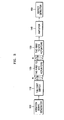
defect detector 340 shown in FIG. 7, where thedefect detector 340 comprises an analog-digital converter 400 and adefect determination unit 420. - The analog-
digital converter 400 converts the Kth vibration signal into a digital signal and outputs the converted signals to thedefect determination unit 420. - The
defect determination unit 420 compares the Kth vibration signal converted into a digital signal with the specific vibration signal that is a digital signal and determine if the printer head has defects. - The
defect determination unit 420 determines if the printer head has defects depending on whether frequency having the largest value of the admittance change corresponds to frequency having the largest value of the admittance change of the specific vibration signal in a case where the Kth vibration signal reflects the changes due to frequency of admittance generated by the vibration of the Kth actuator. - FIG. 10 is a diagram illustrating a specific vibration signal detected from an actuator of a printer head having no defect and a vibration signal detected from an actuator of a printer head having defects.
Graph ① shown in FIG. 10 shows the specific vibration signal detected from the actuator of the printer head having no defect, and graph ② shown in FIG. 10 shows that vibration signal detected from the actuator of the printer head having defects. When there is no defect in the printer head, vibration signals detected from the actuator have the same resonance frequency 677 kHz as ongraph ① shown in FIG. 10. However, when there are defects in the printer head, vibration signals detected from the actuator are different from those of FIG. 10 as on graph ② shown in FIG. 10. The reason that vibration signals are different is that vibration signals of the Kth actuator is not properly detected due to defects such as a crack or adhesion failure, etc. around the Kth actuator. - Therefore, the
defect determination unit 420 checks whether resonance frequency of the Kth vibration signal generated by the vibration of the Kth actuator correspond to resonance frequency of a specific vibration signal of the Kth actuator that is generated when the printer head has no defector or whether both of vibration signals are the same and then determine if the printer head has defects. - Below, a method of detecting defect in the printer head according to the present invention will be described with reference to the accompanying drawings.
- FIG. 11 is a flowchart of an embodiment for explaining a method of detecting defect in the printer head according to the present invention.
- First, vibration signals for vibrating the first to Nth (N is one or more positive integer) actuators are generated (operation 500). Waveforms of various kinds of vibration signals can be generated, and specifically, in the present invention, sinusoidal waveforms are generated.
- After
operation 500, the generated vibration signals are received and output to the Kth (K is any integer ranging from 1 to N) actuator of the first to Nth actuators (operation 502). The generated vibration signals are output to the Kth actuator among the first toNth actuators 120 in order to check whether a crack or an aperture occurs around the Kth actuator. - The Kth actuator is vibrated by the received vibration signals.
- After
operation 502, vibration signals of one or more among the first to Nth actuators vibrating concurrently with the vibration of the Kth actuator are received and the Lth vibration signal that corresponds to a vibration signal of the Lth (L is any integer ranging from 1 to N) actuator adjacent to the Kth actuator, among the received vibration signals is output (operation 504). Specifically, a vibration signal means a maximum voltage change reflecting a frequency change measured from the vibrating actuators. When the actuators are vibrated, a voltage occurs due to physical characteristics of the actuators. Therefore, a maximum voltage change by a frequency change corresponding to frequency change of vibration signals in respect of such generated voltage can be detected. - After
operation 504, the Lth vibration signal is amplified (operation 506). - After
operation 506, the Lth vibration signal is compared with a specific vibration signal of the Lth actuator when there is no defect in the printer head and then defects in the printer head are detected (operation 508). A specific vibration signal means a maximum voltage change depending on a frequency change measured from the first toNth actuators 120 when defects such as a crack or an aperture due to adhesion failure and so on does not occur in the printer head having the first toNth actuators 120. A vibration signal corresponding to a maximum voltage change depending on the frequency change shows the same shape in all of the first or theNth actuators 120 of the printer head having no defect. That is, vibration signals of the first to theNth actuators 120 of the printer head having no defect show that frequency, that is, resonance frequency is the same at the level of the largest value of maximum voltage change. - FIG. 12 is a flowchart of an embodiment for explaining
operation 508 shown in FIG. 11. - The Lth vibration signal is converted into a digital signal (operation 600).
- After
operation 600, the Lth vibration signal converted into a digital signal is compared with specific vibration signal that is a digital signal and defects in the printer head are determined (operation 602). - Defects in the printer head are determined depending on whether frequency having the largest value of maximum voltage change corresponds to frequency having the largest value of maximum voltage change of specific vibration signal when the Lth vibration signal means a frequency change of maximum voltage generated by the vibration of the Lth actuator. As shown in FIG. 6, it is compared whether resonance frequency of the Lth vibration signal generated by the vibration of the Lth actuator corresponds to resonance frequency of a specific vibration signal of the Lth actuator that is generated when there is no defect in the printer head or whether both of vibration signals are the same and then defects in the printer head is determined.
- Below, another embodiment of a method of detecting defect in the printer head according to the present invention will be described with reference to the accompanying drawings.
- FIG. 13 is a flowchart of another embodiment for explaining a method of detecting defect in the printer head according to the present invention.
- First, vibration signals for vibrating the first to Nth (N is one or more positive integer) actuators is generated (operation 700). Specifically, in the present invention, sinusoidal waveforms are generated.
- After
operation 700, the generated vibration signals are received and vibration signals are output to the Kth (K is any integer ranging from 1 to N) actuator among the first to Nth actuators (operation 702). - The Kth actuator is vibrated by the received vibration signals.
- After
operation 702, the Kth vibration signal is amplified (operation 704). - After
operation 704, the Kth vibration signal of the Kth actuator that is made to vibrate by vibration signal is received, the received Kth vibration signal is compared with a specific vibration signal of the Kth actuator when there is no defect in the printer head, and defects in the printer head are detected (operation 706). - A specific vibration signal means an admittance change depending on a frequency change measured from the first to
Nth actuators 120 when defects such as a crack or an aperture due to adhesion failure and so on does not occur in the printer head having the first toNth actuators 120. An admittance change depending on a frequency change measured from the first toNth actuators 120 of the printer head having no defect shows the same shape. That is, vibration signals of the first toNth actuators 120 of the printer head having no defect show that frequency, that is, resonance frequency is the same at the level of the highest value of an admittance change. - FIG. 14 is a flowchart of an embodiment for explaining
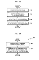
operation 706 shown in FIG. 13. - The Kth vibration signal is converted into a digital signal (operation 800).
- After
operation 800, the Kth vibration signal converted into a digital signal is compared with specific vibration signal that is a digital signal and then defects in the printer head are determined (operation 802). - Defects in the printer head are determined depending on whether frequency having the largest value of an admittance change corresponds to frequency having the largest value of the admittance change of a specific vibration signal when the Kth vibration signal means a change in frequency of admittance generated by the vibration of the Kth actuator.
- As shown in FIG. 10, it is compared whether resonance frequency of the Kth vibration signal generated by the vibration of the Kth actuator corresponds to resonance frequency of a specific vibration signal of the Kth actuator when there is no defect in the printer head or whether both vibration signals are the same and defects in the printer head are determined.
- Below, another embodiment of a method of detecting defects in the printer head according to the present invention will be described with reference to the accompanying drawings.
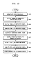
- FIG. 15 is a flowchart of another embodiment for explaining a method of detecting defects in the printer head according to the present invention.
- First, vibration signals for vibrating the first to Nth (N is one or more positive integer) actuators are generated (operation 900). Specifically, sinusoidal waveforms are generated.
- After
operation 900, the generated vibration signals are received and vibration signals are output to the Kth (K is any integer ranging from 1 to N) actuator of the first to Nth actuators (operation 902). - The Kth actuator is vibrated by the received vibration signal.
- After
operation 902, vibration signals of one or more of the first to Nth actuators vibrating concurrently with the vibration of the Kth actuator are received and the L1th vibration signal that corresponds to a vibration signal of the Lth (L is any integer ranging from 1 to N) actuator adjacent to the Kth actuator among the received vibration signals is output (operation 904). - After
operation 904, the L1th vibration signal is amplified (operation 906). - After
operation 906, vibration signals is generated again (operation 908). - After
operation 908, the generated vibration signals are received and vibration signals to the Mth (M is any integer ranging from 1 to N) actuator adjacent to the Lth actuator among the first to Nth actuators are output (operation 910). - After
operation 910, vibration signals of one or more among the first to Nth actuators vibrating concurrently with the vibration of the Mth actuator are received and the L2th vibration signal that is another vibration signal of the Lth actuator among the received vibration signals is output (operation 912). - After
operation 912, the L2th vibration signal is amplified (operation 914). - After
operation 914, the L1th vibration signal is compared with a specific vibration signal of the Lth actuator when there is no defect in the printer head, the L2th vibration signal is compared with the specific vibration signal, and then defects in the printer head are detected (operation 916). - FIG. 16 is a flowchart of an embodiment for explaining
operation 916 shown in FIG. 15. - The L1th vibration signal and the L2th vibration signal are converted into digital signals (operation 1000).
- After
operation 1000, the L1th vibration signal converted into a digital signal is compared with a specific vibration signal that is a digital signal, the L2th vibration signal converted into a digital signal is compared with the specific vibration signal that is a digital signal, and defects in the printer head are determined. - Specifically, defect of the printer head is determined depending on whether a first frequency having the largest of maximum voltage changes of the L1th vibration signal and a second frequency having the largest of maximum voltage changes of the L2th vibration signal correspond to frequency having the largest of maximum voltage changes of a specific vibration signal when the L1th vibration signal and the L2th vibration signal, respectively mean a change in frequency of maximum voltage generated by the vibration of the Lth actuator.
- A specific vibration signal means a maximum voltage change depending on a frequency change respectively measured from the first to
Nth actuators 120 when defects such as a crack or an aperture due to adhesion failure and so on does not occur in the printer head having the first toNth actuators 120. Vibration signals that is a maximum voltage change depending on a frequency change shows the same shape in all of the first toNth actuators 120 of the printer head having no defect. That is, vibration signals of the first toNth actuators 120 of the printer head having no defect show that frequency, that is, resonance frequency is the same at the level of the highest value of maximum voltage change. - Therefore, it is comprehensively taken into account whether the first frequency having the largest of maximum voltage changes of the L1th vibration signal and the second frequency having the largest of maximum voltage changes of the L2th vibration signal correspond to frequency having the largest of maximum voltage changes of a specific vibration signal or whether the L1th vibration signal and the L2th vibration signal correspond to a specific vibration signal of the Lth actuator and then defects in the printer head is determined.
- As described above, a defect detection device and a method of detecting defects in the printer head according to the present invention make it possible to detect defects such as a crack or adhesion failure in the printer head, with simple elements.
- Therefore, the defect detection device and the method of detecting defects in the printer head according to the present invention make it possible to easily determine the quality of the printer head at a low cost.
- While the present invention has been particularly shown and described with reference to exemplary embodiments thereof, it will be understood by those of ordinary skill in the art that various changes in form and details may be made therein without departing from the scope of the present invention as defined by the following claims.
Claims (26)
- A defect detection device of a printer head comprising:first to Nth, where N is a positive integer, actuators for providing a driving force for ejecting ink to ink chambers;a vibration signal generator for generating vibration signals for vibrating the first to Nth actuators;a first switch for receiving the generated vibration signals and outputting the vibration signals to a Kth, where K is any integer ranging from 1 to N, actuator among the first to Nth actuators;a second switch for receiving vibration signals of one or more among the first to Nth actuators vibrating concurrently with the vibration of the Kth actuator and outputting an Lth, where L is any integer ranging from 1 to N, vibration signal that corresponds to a vibration signal of an Lth actuator adjacent to the Kth actuator among the received vibration signals; anda defect detector for comparing the Lth vibration signal output from the second switch with a specific vibration signal of the Lth actuator when there is no defect in a printer head and detecting defects in the printer head.
- The defect detection device of a printer head according to claim 1, wherein the vibration signal generator is arranged to generate sinusoidal waveforms.
- The defect detection device of a printer head according to claim 1 or 2, further comprising an amplifier for amplifying the Lth vibration signal output from the second switch and outputting the amplified Lth vibration signal to the defect detector.
- The defect detection device of a printer head according to any preceding claim, wherein the defect detector comprises an analog-digital converter for converting the Lth vibration signal output from the second switch into a digital signal and a defect determination unit for comparing the Lth vibration signal converted into a digital signal with the specific vibration signal that is a digital signal and determining if the printer head has defects.
- The defect detection device of a printer head according to claim 4, wherein the defect determination unit is arranged to determine if the printer head has defects depending on whether frequency having the largest of the maximum voltage changes corresponds to frequency having the largest of the largest voltage changes of the specific vibration signal when the Lth vibration signal means a frequency change of a maximum voltage generated by the vibration of the Lth actuator.
- A defect detection device of a printer head comprising:first to Nth, where N is a positive integer, actuators for providing a driving force for ejecting ink to ink chambers;a vibration signal generator for generating vibration signals for vibrating the first to Nth actuators;a switch for receiving the generated vibration signals and outputting the vibration signals to a Kth, where K is any integer ranging from 1 to N, actuator among the first to Nth actuators; anda defect detector for receiving the Kth vibration signal of the Kth actuator that is made to vibrate by the vibration signals, comparing the received Kth vibration signal with a specific vibration signal of the Kth actuator when there is no defect in the printer head, and detecting defects in the printer head.
- The defect detection device of a printer head according to claim 6, wherein the vibration signal generator is arranged to generate sinusoidal waveforms.
- The defect detection device of a printer head according to claim 6 or 7, further comprising an amplifier for amplifying the Kth vibration signal and outputting the amplified Kth vibration signal to the defect detector.
- The defect detection device of a printer head according to any preceding claim, wherein the defect detector comprises an analog-digital converter for converting the Kth vibration signal into a digital signal and a defect determination unit for comparing the Kth vibration signal converted into a digital signal with the specific vibration signal that is a digital signal and determining defects in the printer head.
- The defect detection device of a printer head according to claim 9, wherein the defect determination unit is arranged to determine if the printer head has defects depending on whether frequency having the largest of the admittance change correspond to frequency having the largest of the largest admittance change of the specific vibration signal when the Kth vibration signal reflects frequency of an admittance generated by the vibration of the Kth actuator.
- A method of detecting defects in a printer head comprising:generating vibration signals for vibrating first to Nth, where N is a positive integer, actuators;receiving the generated vibration signals and outputting the vibration signals to a Kth, where K is any integer ranging from 1 to N, actuator among the first to Nth actuators;receiving vibration signals of one or more of the first to Nth actuators vibrating concurrently with the vibration of the Kth actuator and outputting an Lth, where L is any integer ranging from 1 to N, vibration signal that corresponds to a vibration signal of an Lth actuator adjacent to the Kth actuator among the received vibration signals; andcomparing the Lth vibration signal with the specific vibration signal of the Lth actuator when there is no defect in the printer head and detecting defects in the printer head.
- The method of detecting defects in a printer head according to claim 11, wherein the step of generating vibration signals comprises generating sinusoidal waveforms.
- The method of detecting defects in a printer head according to claim 11 or 12, further comprising, after the step of receiving vibration signals, a step of amplifying the Lth vibration signal and a step of proceeding to the step of comparing the Lth vibration signal.
- The method of detecting defects in a printer head according to any of claims 11 to 13, wherein the step of comparing the Lth vibration signal comprises:converting the Lth vibration signal into a digital signal; andcomparing the Lth vibration signal converted into a digital signal with the specific vibration signal that is a digital signal and determining defect of the printer head.
- The method of detecting defects in a printer head according to claim 14, wherein in the step of comparing the Lth vibration signal, defects in the printer head is determined depending on whether frequency having the largest of maximum voltage changes corresponds to frequency having the largest of maximum voltage changes of a specific vibration signal when the Lth vibration signal means a frequency change of a maximum voltage generated by the vibration of the Lth actuator.
- A method of detecting defects in a printer head comprising:generating vibration signals for vibrating first to Nth, where N is one or more positive integer, actuators;receiving the generated vibration signals and outputting the vibration signals to a Kth, where K is any integer ranging from 1 to N, actuator among the first to Nth actuators; andreceiving a Kth vibration signal of the Kth actuator that is made to vibrate by the vibration signals, comparing the received Kth vibration signal with a specific vibration signal of the Kth actuator when there is no defect in the printer head, and detecting defects in the printer head.
- The method of detecting defects in a printer head according to claim 16, wherein the step of generating vibration signals comprises generating sinusoidal waveforms.
- The method of detecting defects in a printer head according to claim 16 or 17, further comprising, after the step of receiving the generated vibration signals, a step of amplifying the Kth vibration signal and a step of proceeding to the receiving the Kth vibration signal.
- The method of detecting defects in a printer head according to any of claim 16 to 18, wherein the step of receiving the Kth vibration signal comprises:converting the Kth vibration signal into a digital signal; andcomparing the Kth vibration signal converted into a digital signal with the specific vibration signal that is a digital signal and determining if the printer head has defects.
- The method of detecting defect of a printer head according to claim 19, wherein in the step of comparing the Kth vibration signal, defects in the printer head are determined depending on whether frequency having the largest of an admittance change corresponds to frequency having the largest of an admittance change of a specific vibration signal when the Kth vibration signal means a frequency change of admittance generated by the vibration of the Kth actuator.
- A method of detecting defects in a printer head comprising:generating vibration signals for vibrating first to Nth, where N is a positive integer, actuators;receiving the generated vibration signals and outputting the vibration signals to a Kth, where K is any integer ranging from 1 to N, actuator among the first to Nth actuators;receiving vibration signals of one or more of the first to Nth actuators vibrating concurrently with the vibration of the Kth actuator and outputting an L1th, where L is any integer ranging from 1 to N, vibration signal that corresponds to a vibration signal of an Lth actuator adjacent to the Kth actuator among the received vibration signals;generating the vibration signal again;receiving the generated vibration signal and outputting the vibration signal to an Mth, where M is any integer ranging from 1 to N, actuator adjacent to the Lth actuator among the first to Nth actuators;receiving vibration signals of one or more of the first to Nth actuators vibrating concurrently with the vibration of the Mth actuator and outputting an L2th vibration signal that is another vibration signal of the Lth actuator among the received vibration signals; andcomparing the L1th vibration signal with a specific vibration signal of the Lth actuator when there is no defect in the printer head, comparing the L2th vibration signal with the specific vibration signal, and detecting defects in the printer head.
- The method of detecting defects in a printer head according to claim 21, wherein the step of generating vibration signals comprises generating sinusoidal waveforms.
- The method of detecting defects in a printer head according to claim 21 or 22, further comprising, after the step of receiving vibration signals:a step of amplifying the L1th vibration signal and a step of proceeding to the step of generating the vibration signal again; anda step of amplifying the L2th vibration signal after the receiving vibration signals and a step of proceeding to the step of comparing the L1th vibration signal.
- The method of detecting defect of a printer head according to any of claims 21 to 23, wherein the step of comparing the L1th vibration signal comprises:converting the L1th vibration signal and the L2th vibration signal into digital signals; andcomparing the L1th vibration signal converted into a digital signal with the specific vibration signal that is a digital signal, comparing the L2th vibration signal converted into a digital signal with the specific vibration signal that is a digital signal, and determining if the printer head has defects.
- The method of detection defect of a printer head according to claim 24, wherein in the step of comparing the L1th vibration signal, defects in the printer head are determined depending on whether a first frequency having the largest of maximum voltage changes of the L1th vibration signal and a second frequency having the largest of maximum voltage change of the L2th vibration signal corresponds to frequency having the largest of maximum voltage changes of a specific vibration signal when the L1th vibration signal and the L2th vibration signal, respectively means frequency change of a maximum voltage generated by the vibration of the Lth actuator.
- A defect detection device for a printer head, the device comprising:a plurality of actuators arranged to provide a driving force for ejecting ink to ink chambers;a vibration signal generator arranged to generate a first vibration signal for vibrating one of the actuators; anda defect detector for detecting a defect in the printer head, the detector being arranged to receive a second vibration signal generated by a vibrating one of the actuators, and to compare the second vibration signal with a specific vibration signal generated by the actuators when there is no defect in the printer head.
Applications Claiming Priority (1)
| Application Number | Priority Date | Filing Date | Title |
|---|---|---|---|
| KR1020040106519A KR100647301B1 (en) | 2004-12-15 | 2004-12-15 | Device and method for detecting defect of print head |
Publications (3)
| Publication Number | Publication Date |
|---|---|
| EP1671799A2 true EP1671799A2 (en) | 2006-06-21 |
| EP1671799A3 EP1671799A3 (en) | 2008-10-15 |
| EP1671799B1 EP1671799B1 (en) | 2012-01-18 |
Family
ID=35998599
Family Applications (1)
| Application Number | Title | Priority Date | Filing Date |
|---|---|---|---|
| EP05257654A Expired - Lifetime EP1671799B1 (en) | 2004-12-15 | 2005-12-14 | Defect detection device of a printer head and associated method |
Country Status (4)
| Country | Link |
|---|---|
| US (1) | US7571975B2 (en) |
| EP (1) | EP1671799B1 (en) |
| JP (1) | JP4727406B2 (en) |
| KR (1) | KR100647301B1 (en) |
Families Citing this family (6)
| Publication number | Priority date | Publication date | Assignee | Title |
|---|---|---|---|---|
| US7744184B2 (en) * | 2007-01-23 | 2010-06-29 | Marvell World Trade Ltd. | Mechanical dithering of printing mechanisms |
| US8888226B1 (en) | 2013-06-25 | 2014-11-18 | Hewlett-Packard Development Company, L.P. | Crack detection circuits for printheads |
| ES2892176T3 (en) * | 2015-01-30 | 2022-02-02 | Hewlett Packard Development Co | Crack detection for printheads that have multiple printhead dies |
| CN113396066B (en) | 2019-02-06 | 2022-12-09 | 惠普发展公司,有限责任合伙企业 | Die for a printhead and method of forming crack detector traces on a die |
| US12115790B2 (en) | 2019-05-15 | 2024-10-15 | Hewlett-Packard Development Company, L.P. | Integrated circuits including strain gauge sensors |
| JP7363213B2 (en) * | 2019-08-30 | 2023-10-18 | セイコーエプソン株式会社 | Liquid injection device and method of controlling the liquid injection device |
Family Cites Families (9)
| Publication number | Priority date | Publication date | Assignee | Title |
|---|---|---|---|---|
| EP0825423A1 (en) * | 1996-07-24 | 1998-02-25 | Peter Hildebrandt | Device for measuring and/or monitoring the level of a liquid |
| JPH10217466A (en) * | 1997-02-12 | 1998-08-18 | Ricoh Co Ltd | Inkjet head |
| JP3541866B2 (en) * | 1997-08-21 | 2004-07-14 | 日立プリンティングソリューションズ株式会社 | Method for diagnosing adhesion failure of inkjet head |
| US6375299B1 (en) * | 1998-11-02 | 2002-04-23 | Encad, Inc. | Faulty ink ejector detection in an ink jet printer |
| NL1012811C2 (en) * | 1999-08-12 | 2001-02-13 | Ocu Technologies B V | Method to increase the reliability of an inkjet printer and an inkjet printer suitable for applying this method. |
| WO2002004215A1 (en) * | 2000-07-07 | 2002-01-17 | Seiko Epson Corporation | Liquid container, ink-jet recording apparatus, device and method for controlling the apparatus, liquid consumption sensing device and method |
| JP2003291357A (en) * | 2002-04-02 | 2003-10-14 | Matsushita Electric Ind Co Ltd | An inkjet head adjustment method and manufacturing method, and an inkjet recording apparatus. |
| JP2004009501A (en) * | 2002-06-06 | 2004-01-15 | Hitachi Printing Solutions Ltd | Inkjet printer |
| CN1286645C (en) * | 2003-02-28 | 2006-11-29 | 精工爱普生株式会社 | Liquid droplet discharge device and liquid droplet discharge head discharge abnormality detection and judgment method |
-
2004
- 2004-12-15 KR KR1020040106519A patent/KR100647301B1/en not_active Expired - Fee Related
-
2005
- 2005-12-08 JP JP2005355340A patent/JP4727406B2/en not_active Expired - Fee Related
- 2005-12-14 EP EP05257654A patent/EP1671799B1/en not_active Expired - Lifetime
- 2005-12-14 US US11/302,400 patent/US7571975B2/en not_active Expired - Fee Related
Also Published As
| Publication number | Publication date |
|---|---|
| US20060125870A1 (en) | 2006-06-15 |
| US7571975B2 (en) | 2009-08-11 |
| EP1671799A3 (en) | 2008-10-15 |
| JP2006168359A (en) | 2006-06-29 |
| KR100647301B1 (en) | 2006-11-23 |
| KR20060067671A (en) | 2006-06-20 |
| JP4727406B2 (en) | 2011-07-20 |
| EP1671799B1 (en) | 2012-01-18 |
Similar Documents
| Publication | Publication Date | Title |
|---|---|---|
| US6682162B2 (en) | Printing apparatus with measuring circuit for diagnosis of condition of each electromechanical transducer | |
| JP5978744B2 (en) | Liquid ejection device, inspection method, and program | |
| JP4114638B2 (en) | Droplet discharge device and discharge abnormality detection method thereof | |
| US10189246B2 (en) | Jetting device with filter status detection | |
| EP2955026A1 (en) | Liquid droplet ejection device, liquid droplet ejection method and inkjet recording apparatus | |
| JP7198114B2 (en) | LIQUID JET HEAD AND LIQUID JET RECORDING APPARATUS | |
| KR20120093619A (en) | Error detecting apparatus of inkjet printer head and error detecting method thereof | |
| CN106004047A (en) | Liquid discharge apparatus and control method thereof | |
| JP2018167466A (en) | COMMUNICATION DEVICE AND RECORDING DEVICE HAVING THE SAME | |
| JP6613840B2 (en) | Inspection method of liquid discharge head and liquid discharge apparatus | |
| JP3213431B2 (en) | Ink jet recording apparatus and ink remaining amount detecting method | |
| EP1671799B1 (en) | Defect detection device of a printer head and associated method | |
| US11247453B2 (en) | Liquid ejecting head and liquid-ejecting recording apparatus | |
| JP6759730B2 (en) | Liquid discharge device, drive waveform control method | |
| EP3670188B1 (en) | A method for detecting nozzle failures in an inkjet print head | |
| JP2006088577A (en) | Inspection device of inkjet head | |
| JP4561229B2 (en) | Inkjet recording apparatus and inkjet recording method | |
| JPH08336986A (en) | Ink ejection monitoring device | |
| EP1688261B1 (en) | A method of preventing air bubbles in an inkjet printer and an ink jet printer which has been modified for this method to be applied | |
| JP2020082456A (en) | Liquid discharge device | |
| US20070268324A1 (en) | Method and apparatus for calculating natural frequency of an ink-jet head | |
| US20260116067A1 (en) | Printing apparatus, printing method and non-transitory computer-readable recording medium therefor | |
| US10449760B2 (en) | Method for cancelling electric crosstalk in a printhead | |
| JP7119511B2 (en) | Device for ejecting liquid and method for detecting abnormality in device for ejecting liquid | |
| JP2011178152A (en) | Inkjet recorder |
Legal Events
| Date | Code | Title | Description |
|---|---|---|---|
| PUAI | Public reference made under article 153(3) epc to a published international application that has entered the european phase |
Free format text: ORIGINAL CODE: 0009012 |
|
| AK | Designated contracting states |
Kind code of ref document: A2 Designated state(s): AT BE BG CH CY CZ DE DK EE ES FI FR GB GR HU IE IS IT LI LT LU LV MC NL PL PT RO SE SI SK TR |
|
| AX | Request for extension of the european patent |
Extension state: AL BA HR MK YU |
|
| PUAL | Search report despatched |
Free format text: ORIGINAL CODE: 0009013 |
|
| AK | Designated contracting states |
Kind code of ref document: A3 Designated state(s): AT BE BG CH CY CZ DE DK EE ES FI FR GB GR HU IE IS IT LI LT LU LV MC NL PL PT RO SE SI SK TR |
|
| AX | Request for extension of the european patent |
Extension state: AL BA HR MK YU |
|
| 17P | Request for examination filed |
Effective date: 20090415 |
|
| 17Q | First examination report despatched |
Effective date: 20090515 |
|
| AKX | Designation fees paid |
Designated state(s): DE FR GB |
|
| RAP1 | Party data changed (applicant data changed or rights of an application transferred) |
Owner name: SAMSUNG ELECTRO-MECHANICS CO., LTD. |
|
| GRAP | Despatch of communication of intention to grant a patent |
Free format text: ORIGINAL CODE: EPIDOSNIGR1 |
|
| GRAS | Grant fee paid |
Free format text: ORIGINAL CODE: EPIDOSNIGR3 |
|
| GRAA | (expected) grant |
Free format text: ORIGINAL CODE: 0009210 |
|
| AK | Designated contracting states |
Kind code of ref document: B1 Designated state(s): DE FR GB |
|
| REG | Reference to a national code |
Ref country code: GB Ref legal event code: FG4D |
|
| REG | Reference to a national code |
Ref country code: DE Ref legal event code: R096 Ref document number: 602005032252 Country of ref document: DE Effective date: 20120315 |
|
| PLBE | No opposition filed within time limit |
Free format text: ORIGINAL CODE: 0009261 |
|
| STAA | Information on the status of an ep patent application or granted ep patent |
Free format text: STATUS: NO OPPOSITION FILED WITHIN TIME LIMIT |
|
| 26N | No opposition filed |
Effective date: 20121019 |
|
| REG | Reference to a national code |
Ref country code: DE Ref legal event code: R097 Ref document number: 602005032252 Country of ref document: DE Effective date: 20121019 |
|
| REG | Reference to a national code |
Ref country code: FR Ref legal event code: PLFP Year of fee payment: 11 |
|
| PGFP | Annual fee paid to national office [announced via postgrant information from national office to epo] |
Ref country code: GB Payment date: 20151023 Year of fee payment: 11 Ref country code: DE Payment date: 20151019 Year of fee payment: 11 |
|
| PGFP | Annual fee paid to national office [announced via postgrant information from national office to epo] |
Ref country code: FR Payment date: 20151026 Year of fee payment: 11 |
|
| REG | Reference to a national code |
Ref country code: DE Ref legal event code: R119 Ref document number: 602005032252 Country of ref document: DE |
|
| GBPC | Gb: european patent ceased through non-payment of renewal fee |
Effective date: 20161214 |
|
| REG | Reference to a national code |
Ref country code: FR Ref legal event code: ST Effective date: 20170831 |
|
| PG25 | Lapsed in a contracting state [announced via postgrant information from national office to epo] |
Ref country code: FR Free format text: LAPSE BECAUSE OF NON-PAYMENT OF DUE FEES Effective date: 20170102 |
|
| PG25 | Lapsed in a contracting state [announced via postgrant information from national office to epo] |
Ref country code: GB Free format text: LAPSE BECAUSE OF NON-PAYMENT OF DUE FEES Effective date: 20161214 Ref country code: DE Free format text: LAPSE BECAUSE OF NON-PAYMENT OF DUE FEES Effective date: 20170701 |