EP1671406B1 - Systemes et procedes faisant intervenir un projectile electrifie - Google Patents
Systemes et procedes faisant intervenir un projectile electrifie Download PDFInfo
- Publication number
- EP1671406B1 EP1671406B1 EP04821628A EP04821628A EP1671406B1 EP 1671406 B1 EP1671406 B1 EP 1671406B1 EP 04821628 A EP04821628 A EP 04821628A EP 04821628 A EP04821628 A EP 04821628A EP 1671406 B1 EP1671406 B1 EP 1671406B1
- Authority
- EP
- European Patent Office
- Prior art keywords
- electrode
- target
- projectile
- impact
- away
- Prior art date
- Legal status (The legal status is an assumption and is not a legal conclusion. Google has not performed a legal analysis and makes no representation as to the accuracy of the status listed.)
- Not-in-force
Links
- 238000000034 method Methods 0.000 title claims description 29
- 230000003100 immobilizing effect Effects 0.000 claims abstract description 12
- 239000003380 propellant Substances 0.000 claims description 14
- 230000004044 response Effects 0.000 claims description 8
- 230000000452 restraining effect Effects 0.000 claims description 5
- 230000000694 effects Effects 0.000 claims description 4
- 238000004891 communication Methods 0.000 claims description 3
- 230000001747 exhibiting effect Effects 0.000 claims 1
- 241001465754 Metazoa Species 0.000 description 14
- 239000012190 activator Substances 0.000 description 9
- 210000001519 tissue Anatomy 0.000 description 8
- 230000000638 stimulation Effects 0.000 description 7
- IJGRMHOSHXDMSA-UHFFFAOYSA-N Atomic nitrogen Chemical compound N#N IJGRMHOSHXDMSA-UHFFFAOYSA-N 0.000 description 6
- 239000007789 gas Substances 0.000 description 6
- 238000000926 separation method Methods 0.000 description 6
- 238000005516 engineering process Methods 0.000 description 5
- 210000002027 skeletal muscle Anatomy 0.000 description 5
- 210000004027 cell Anatomy 0.000 description 4
- 230000008859 change Effects 0.000 description 4
- 230000007246 mechanism Effects 0.000 description 4
- RYGMFSIKBFXOCR-UHFFFAOYSA-N Copper Chemical compound [Cu] RYGMFSIKBFXOCR-UHFFFAOYSA-N 0.000 description 3
- 239000004727 Noryl Substances 0.000 description 3
- 229920001207 Noryl Polymers 0.000 description 3
- 229910000831 Steel Inorganic materials 0.000 description 3
- 229920000122 acrylonitrile butadiene styrene Polymers 0.000 description 3
- 230000009471 action Effects 0.000 description 3
- 238000006243 chemical reaction Methods 0.000 description 3
- 229910052802 copper Inorganic materials 0.000 description 3
- 239000010949 copper Substances 0.000 description 3
- 230000005484 gravity Effects 0.000 description 3
- 239000003721 gunpowder Substances 0.000 description 3
- 230000003387 muscular Effects 0.000 description 3
- 230000035515 penetration Effects 0.000 description 3
- 229920003023 plastic Polymers 0.000 description 3
- 239000004033 plastic Substances 0.000 description 3
- 229920000642 polymer Polymers 0.000 description 3
- 230000002829 reductive effect Effects 0.000 description 3
- 230000006641 stabilisation Effects 0.000 description 3
- 238000011105 stabilization Methods 0.000 description 3
- 239000010959 steel Substances 0.000 description 3
- 238000012360 testing method Methods 0.000 description 3
- 238000013519 translation Methods 0.000 description 3
- CURLTUGMZLYLDI-UHFFFAOYSA-N Carbon dioxide Chemical compound O=C=O CURLTUGMZLYLDI-UHFFFAOYSA-N 0.000 description 2
- 230000004913 activation Effects 0.000 description 2
- 238000013459 approach Methods 0.000 description 2
- 238000003491 array Methods 0.000 description 2
- 239000003990 capacitor Substances 0.000 description 2
- 230000007123 defense Effects 0.000 description 2
- 239000013013 elastic material Substances 0.000 description 2
- 239000002360 explosive Substances 0.000 description 2
- 230000006870 function Effects 0.000 description 2
- 239000000463 material Substances 0.000 description 2
- 238000012544 monitoring process Methods 0.000 description 2
- 230000004118 muscle contraction Effects 0.000 description 2
- 230000004220 muscle function Effects 0.000 description 2
- 210000005036 nerve Anatomy 0.000 description 2
- 229910052757 nitrogen Inorganic materials 0.000 description 2
- 230000037361 pathway Effects 0.000 description 2
- 230000000717 retained effect Effects 0.000 description 2
- 229910001220 stainless steel Inorganic materials 0.000 description 2
- 239000010935 stainless steel Substances 0.000 description 2
- 241000282887 Suidae Species 0.000 description 1
- 230000001133 acceleration Effects 0.000 description 1
- 230000003213 activating effect Effects 0.000 description 1
- 229910002092 carbon dioxide Inorganic materials 0.000 description 1
- 239000001569 carbon dioxide Substances 0.000 description 1
- 230000006835 compression Effects 0.000 description 1
- 238000007906 compression Methods 0.000 description 1
- 239000004020 conductor Substances 0.000 description 1
- 230000008878 coupling Effects 0.000 description 1
- 238000010168 coupling process Methods 0.000 description 1
- 238000005859 coupling reaction Methods 0.000 description 1
- 230000002498 deadly effect Effects 0.000 description 1
- 230000007423 decrease Effects 0.000 description 1
- 230000001419 dependent effect Effects 0.000 description 1
- 238000005474 detonation Methods 0.000 description 1
- 238000010586 diagram Methods 0.000 description 1
- 229910001873 dinitrogen Inorganic materials 0.000 description 1
- 229920001971 elastomer Polymers 0.000 description 1
- 239000004744 fabric Substances 0.000 description 1
- 229920001821 foam rubber Polymers 0.000 description 1
- 239000007943 implant Substances 0.000 description 1
- 230000006872 improvement Effects 0.000 description 1
- 230000002452 interceptive effect Effects 0.000 description 1
- 231100000518 lethal Toxicity 0.000 description 1
- 230000001665 lethal effect Effects 0.000 description 1
- 230000000670 limiting effect Effects 0.000 description 1
- 230000007257 malfunction Effects 0.000 description 1
- 238000004519 manufacturing process Methods 0.000 description 1
- 238000012986 modification Methods 0.000 description 1
- 230000004048 modification Effects 0.000 description 1
- 210000003205 muscle Anatomy 0.000 description 1
- 210000004126 nerve fiber Anatomy 0.000 description 1
- 210000000653 nervous system Anatomy 0.000 description 1
- 210000002569 neuron Anatomy 0.000 description 1
- JCXJVPUVTGWSNB-UHFFFAOYSA-N nitrogen dioxide Inorganic materials O=[N]=O JCXJVPUVTGWSNB-UHFFFAOYSA-N 0.000 description 1
- 231100001160 nonlethal Toxicity 0.000 description 1
- 238000005381 potential energy Methods 0.000 description 1
- 239000000843 powder Substances 0.000 description 1
- 230000029058 respiratory gaseous exchange Effects 0.000 description 1
- 230000035939 shock Effects 0.000 description 1
- 210000002460 smooth muscle Anatomy 0.000 description 1
- 210000000689 upper leg Anatomy 0.000 description 1
- 230000002747 voluntary effect Effects 0.000 description 1
Images


Classifications
-
- F—MECHANICAL ENGINEERING; LIGHTING; HEATING; WEAPONS; BLASTING
- F42—AMMUNITION; BLASTING
- F42B—EXPLOSIVE CHARGES, e.g. FOR BLASTING, FIREWORKS, AMMUNITION
- F42B5/00—Cartridge ammunition, e.g. separately-loaded propellant charges
- F42B5/02—Cartridges, i.e. cases with charge and missile
- F42B5/24—Cartridges, i.e. cases with charge and missile for cleaning; for cooling; for lubricating ; for wear reducing
-
- F—MECHANICAL ENGINEERING; LIGHTING; HEATING; WEAPONS; BLASTING
- F41—WEAPONS
- F41H—ARMOUR; ARMOURED TURRETS; ARMOURED OR ARMED VEHICLES; MEANS OF ATTACK OR DEFENCE, e.g. CAMOUFLAGE, IN GENERAL
- F41H13/00—Means of attack or defence not otherwise provided for
- F41H13/0012—Electrical discharge weapons, e.g. for stunning
- F41H13/0031—Electrical discharge weapons, e.g. for stunning for remote electrical discharge by means of a wireless projectile
-
- F—MECHANICAL ENGINEERING; LIGHTING; HEATING; WEAPONS; BLASTING
- F42—AMMUNITION; BLASTING
- F42B—EXPLOSIVE CHARGES, e.g. FOR BLASTING, FIREWORKS, AMMUNITION
- F42B12/00—Projectiles, missiles or mines characterised by the warhead, the intended effect, or the material
-
- F—MECHANICAL ENGINEERING; LIGHTING; HEATING; WEAPONS; BLASTING
- F42—AMMUNITION; BLASTING
- F42B—EXPLOSIVE CHARGES, e.g. FOR BLASTING, FIREWORKS, AMMUNITION
- F42B12/00—Projectiles, missiles or mines characterised by the warhead, the intended effect, or the material
- F42B12/02—Projectiles, missiles or mines characterised by the warhead, the intended effect, or the material characterised by the warhead or the intended effect
- F42B12/36—Projectiles, missiles or mines characterised by the warhead, the intended effect, or the material characterised by the warhead or the intended effect for dispensing materials; for producing chemical or physical reaction; for signalling ; for transmitting information
-
- F—MECHANICAL ENGINEERING; LIGHTING; HEATING; WEAPONS; BLASTING
- F42—AMMUNITION; BLASTING
- F42B—EXPLOSIVE CHARGES, e.g. FOR BLASTING, FIREWORKS, AMMUNITION
- F42B8/00—Practice or training ammunition
-
- H—ELECTRICITY
- H01—ELECTRIC ELEMENTS
- H01T—SPARK GAPS; OVERVOLTAGE ARRESTERS USING SPARK GAPS; SPARKING PLUGS; CORONA DEVICES; GENERATING IONS TO BE INTRODUCED INTO NON-ENCLOSED GASES
- H01T23/00—Apparatus for generating ions to be introduced into non-enclosed gases, e.g. into the atmosphere
-
- H—ELECTRICITY
- H05—ELECTRIC TECHNIQUES NOT OTHERWISE PROVIDED FOR
- H05C—ELECTRIC CIRCUITS OR APPARATUS SPECIALLY DESIGNED FOR USE IN EQUIPMENT FOR KILLING, STUNNING, OR GUIDING LIVING BEINGS
- H05C1/00—Circuits or apparatus for generating electric shock effects
- H05C1/04—Circuits or apparatus for generating electric shock effects providing pulse voltages
- H05C1/06—Circuits or apparatus for generating electric shock effects providing pulse voltages operating only when touched
Definitions
- Embodiments of the present invention generally relate to systems and methods using an electrified projectile for reducing mobility in a person or animal.
- a conducted energy weapon typically fires two projectiles from a handheld device to a range of about 15 feet to deliver a stimulus signal to the target.
- the projectiles remain tethered to a power supply in the handheld device by two fine, insulated wires. Tethered projectiles are also called darts.
- a stimulus signal comprising a series of relatively high voltage pulses are delivered through the wires and into the target, causing pain in the target.
- a high impedance gap e.g., air or clothing
- the stimulus signal conventionally includes a relatively high voltage (e.g., about 50,000 volts) to ionize a pathway across such a gap of up to 2 inches. Consequently, the stimulus signal may be conducted through the target's tissue without penetration of the projectile into the tissue. Effectiveness of a stimulus signal of the type described by Cover is limited. For example, tests showed that most human targets who were given a physical motor task to perform during or after being struck with the projectiles and subjected to a relatively high voltage (e.g., fight against the person armed with the weapon) could accomplish the task.
- a relatively high voltage e.g., fight against the person armed with the weapon
- stun guns omit the projectiles and deliver essentially the same stimulus signal to a target when the target is in close proximity to the weapon. These weapons have limited application because close proximity typically decreases the safety of the person armed with the weapon.
- Another conventional conducted energy weapon uses compressed gas to propel the projectile as described for example in U.S. Patent 5,078,117 to Cover .
- This propulsion system uses a relatively small primer that is detonated by an electric charge in the weapon. The detonation forces a cylinder of compressed gas such as nitrogen onto a puncturing device to release an amount of compressed nitrogen that propels the projectile out of the weapon.
- EMD Electro-Muscular Disruption
- a weapon of this type may include 8 AA size 1.5 volt batteries, a large capacity capacitor, and transformers to generate a 26-watt EMD output to a tethered projectile (e.g., a dart).
- a tethered projectile e.g., a dart
- a two pulse waveform of the type described in U.S. Patent Application 10/447,447 to Magne Nerheim filed February 11, 2003 provides a relatively high voltage, low amperage pulse (to form an arc through a gap as discussed above) followed by a relatively lower voltage, higher amperage pulse (to stimulate the target). Effects on skeletal muscles may be achieved with 80% less power than EMD waveforms, discussed above.
- a consistent electrode separation regardless of the distance from the handheld device to the target is provided in a system as described in U.S. Patent Number 6,575,073 to McNulty .
- a larger projectile carrying a first electrode includes a range sensor.
- the larger projectile fires a smaller projectile carrying the second electrode.
- Higher cost and lower reliability result.
- a range sensing system could malfunction by having a narrow field of view, for example, where the device could impact the target at such an oblique angle that the range sensor never effectively senses the target until it is too close to effectively deploy the second electrode.
- the range sensor might detect an object next to its trajectory and prematurely fire the second electrode, causing the second electrode to miss the target.
- an apparatus for immobilizing a target includes electrodes deployed after contact is made between the apparatus and the target. Spacing of deployed electrodes may be more accurate and/or more repeatable for more effective delivery of an immobilizing stimulus signal.
- a system for immobilizing a target includes a launch device and a projectile.
- the projectile is not tethered to the launch device.
- the projectile deploys an electrode after the projectile contacts the target.
- a distance between electrodes is less dependent on range from the launch device to the target. Consequently, targets at various ranges receive more uniform stimulation.
- a larger number of applications for energy weapons may be met with projectiles, methods, and systems of the present invention due to various aspects including lower cost, lower complexity, higher reliability, greater range and accuracy, and improved effectiveness in various combinations according to the implementation.
- a method for immobilizing a target includes in any order: (a) providing a first electrode, a second electrode, a signal generator, and an electrode deployment apparatus that deploys the second electrode; (b) restraining movement of the second electrode with respect to the first electrode; (c) removing restraint of the second electrode with respect to the first electrode after the first electrode makes contact with the target, so that the second electrode initially moves away from the target to make contact with the target a distance away from where the first electrode made contact with the target; and (d) providing a stimulus signal via the signal generator, the first electrode, and the second electrode.
- a device for immobilizing a target includes: first and second portions.
- the first portion includes a first electrode for contact with a target.
- the second portion includes a second electrode for contact with the target and a tether that maintains electrical communication between the first portion and the second portion.
- the device further includes a signal generator that provides a stimulus signal via the first electrode and the second electrode to immobilize the target; and coupling that couples the first portion to the second portion to transport the immobilization device as a unit, and that, after the first portion makes contact with the target, releases the second portion from the first portion, so that the second portion moves away from the target, to deploy the second electrode a distance away from the first electrode.
- a system delivers a stimulus signal to an animal (e.g., a human) to immobilize the animal.
- Immobilization is suitably temporary, for example, to remove the animal from danger or to thwart actions by the animal such as for applying more permanent restraints on mobility.
- Electrodes may come into contact with the animal by the animal's own action (e.g., motion of the animal toward an electrode), by propelling the electrode toward the animal (e.g., electrodes being part of an electrified projectile), by deployment mechanisms, and/or by gravity.
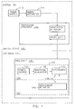
- system 100 of FIGs. 1-9 includes launch device 102 and cartridge 104.
- Launch device 104 includes power supply 112, aiming apparatus 114, and propulsion apparatus 116.
- Propulsion apparatus 116 includes propulsion activator 118 and propellant 120.
- propellant 120 is part of cartridge 104.
- launch device 104 Any conventional materials and technology may be employed in the manufacture and operation of launch device 104.
- power supply 112 may include one or more rechargeable batteries
- aiming apparatus 114 may include a laser gun sight
- propulsion activator 118 may include a mechanical trigger similar in some respects to the trigger of a hand gun
- propellant 120 may include compressed nitrogen gas.
- cartridge 104 is mounted on or in launch device 104, manual operation by the user causes a projectile bearing electrodes to be propelled away from launch device 104 and toward a target (e.g., an animal such as a human), and after the electrodes become electrically coupled to the target, a stimulus signal is delivered through a portion of the tissue of the target.
- launch device is handheld and operable in a manner similar to a conventional hand gun.
- Cartridge 104 includes projectile 132 having power source 134, waveform generator 136, and electrode deployment apparatus 138.
- Electrode deployment apparatus 138 includes deployment activator 140 and one or more electrodes 142.
- Power source 134 may include any conventional battery selected for relatively high energy capacity to volume ratio.
- Waveform generator 136 receives power from power source 134 and generates a conventional stimulus signal using conventional circuitry.
- the stimulus signal is delivered into a circuit that is completed by a path through the target via electrodes.
- Power source 134, waveform generator 136, electrodes 142 cooperate to form a stimulus signal delivery circuit that may further include one or more additional electrodes not deployed by deployment activator 142 (e.g., placed by impact of projectile 132).
- Projectile 132 may include a body having compartments or other structures for mounting power source 134, a circuit assembly for waveform generator 136, and electrode deployment apparatus 138.
- the body may be formed in a conventional shape for ballistics (e.g., a wetted aerodynamic form).
- An electrode deployment apparatus includes any mechanism that moves electrodes from a stowed configuration to a deployed configuration.
- a stowed configuration provides aerodynamic stability for accurate travel of the projectile.
- a deployed configuration completes a stimulus signal delivery circuit directly via impaling the tissue or indirectly via an arc into the tissue.
- a separation of about 17.8 cm (7 inches) has been found to be more effective than a separation of about 3.8 cm (1.5 inches); and, longer separations may also be suitable such as an electrode in the thigh and another in the hand. When the electrodes are further apart, the stimulus signal apparently passes through more tissue, creating more effective stimulation.
- deployment of electrodes is activated after contact is made by projectile 132 and the target.
- Contact may be determined by a change in orientation of the deployment activator; a change in position of the deployment activator with respect to the projectile body; a change in direction, velocity, or acceleration of the deployment activator; and/or a change in conductivity between electrodes (e.g., 142 or electrodes placed by impact of projectile 132 with the target).
- a deployment activator 140 that detects impact by mechanical characteristics and deploys electrodes by the release or redirection of mechanical energy is preferred for low cost projectiles.
- Electrodes may be facilitated by behavior of the target.
- one or more closely spaced electrodes at the front of the projectile may attach to a target to excite a painful reaction in the target.
- One or more electrodes may be exposed and suitably directed (e.g., away from the target). Exposure may be either during flight or after impact. Pain in the target may be caused by the barb of the electrode stuck into the target's flesh or, if there are two closely spaced electrodes, delivery of a stimulus signal between the closely spaced electrodes. While these electrodes may be too close together for suitable immobilization, the stimulus signal may create sufficient pain and disorientation.
- a typical response behavior to pain is to grab at the perceived cause of pain with the hands (or mouth, in the case of an animal) in an attempt to remove the electrodes.
- This so called "hand trap” approach uses this typical response behavior to implant the one or more exposed electrodes into the hand (or mouth) of the target. By grabbing at the projectile, the one or more exposed electrodes impale the target's hand (or mouth).
- the exposed electrodes in the hand (or mouth) of the target are generally well spaced apart from other electrodes so that stimulation between an other electrode and an exposed electrode may allow suitable immobilization.
- launch device 102, cartridge 104, and projectile 132 are omitted; and power source 134, waveform generator 136, and electrode deployment apparatus 138 are formed as an immobilization device 150 adapted for other conventional forms of placement on or in the vicinity of the target.
- deployment apparatus 138 is omitted and electrodes 142 are placed by target behavior and/or gravity.
- Immobilization device 150 may be packaged using conventional technology for personal security (e.g., planting in a human target's clothing or in an animals hide for future activation), facility security (e.g., providing time for surveillance cameras, equipment shutdown, or emergency response), or military purposes (e.g., land mine).
- Projectile 132 may be lethal or non-lethal. In alternate implementations, projectile 132 includes any conventional technology for administering deadly force.
- Immobilization as discussed herein includes any restraint of voluntary motion by the target.
- immobilization may include causing pain or interfering with normal muscle function. Immobilization need not include all motion or all muscles of the target. Preferably, involuntary muscle functions (e.g., for circulation and respiration) are not disturbed.
- involuntary muscle functions e.g., for circulation and respiration
- loss of function of one or more skeletal muscles accomplishes suitable immobilization.
- suitable intensity of pain is caused to upset the target's ability to complete a motor task, thereby incapacitating and disabling the target.
- launch device 102 may include or substitute conventionally available weapons (e.g., firearms, grenade launchers, vehicle mounted artillery).
- Projectile 132 may be delivered via an explosive charge 120 (e.g., gunpowder, black powder). Projectile 132 may alternatively be propelled via a discharge of compressed gas (e.g., nitrogen or carbon dioxide) and/or a rapid release of pressure (e.g., spring force, or force created by a chemical reaction such as a reaction of the type used in automobile air-bag deployment).
- compressed gas e.g., nitrogen or carbon dioxide
- pressure e.g., spring force, or force created by a chemical reaction such as a reaction of the type used in automobile air-bag deployment.
- Projectile 132 may be tethered to launch device 102 and suitable circuitry in launch device 102 (not shown) using any conventional technology for purposes of providing substitute or auxiliary power to power source 134; triggering, retriggering, or controlling waveform generator 136; activating, reactivating, or controlling deployment; and/or receiving signals at launch device 102 provided from electrodes 142 in cooperation with instrumentation in projectile 132 (not shown).
- Projectiles 132 for use in system 100 may be of one or more of several implementations.
- the deployment activators and electrodes discussed below may be combined in any manner to produce a projectile suitable for one or more purposes of system 100 discussed above.
- the likelihood of success is increased for placing two electrodes at a sufficient distance apart from each other for immobilization.
- a projectile deploys an electrode from the rear of the projectile after impact of the projectile and the target.
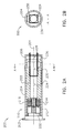
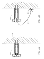
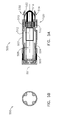
- a projectile 200 of FIGs. 2-4 has four configurations: (1) a stowed configuration (FIG. 2A), where fins and electrodes are in storage locations and orientations; (2) an in flight configuration (FIG. 2C); (3) an impact configuration after contact with the target (FIG. 4A); and (4) an electrode deployed configuration (FIG. 4B).
- Projectile 200 includes plug 202 attached (e.g., close fitted, formed, crimped, or sealed) to body 204. Forward force against plug 202 propels projectile 200 forward.
- Body 204 includes casing 206, electrode pod 210, translating element 222, battery 224, and circuit assembly 230.
- Plug 202 may include propellant 120 (e.g., 3 to 4 grains of gunpowder for a 30 gram projectile).
- propellant 120 in launch device 102 or projectile 132 includes a 40mm grenade shell.
- Projectile 200 may include a mechanical shock absorbing tip (not shown) such as foam rubber or the like.
- plug 202 or launch device 102 includes a self-contained pressurized gas charge that propels projectile 200 when the pressurized gas is released. As discussed below, propellant is omitted from plug 202 and is contained in launch device 102.
- Casing 206 provides an aerodynamic housing for components of projectile 200 and cooperates with translating element 222. Casing may support one or more fins 262 for improving its flight characteristics. An alternate implementation omits fins 262 for reduced cost.
- casing 206 is made of a polymer such as NORYL® or ABS plastic and is shaped and/or dimensioned in a suitable fashion to be delivered by the desired launch device. Fins 262 may also be made of plastic and may include copper or steel springs and/or pins for causing movement toward or retaining the deployed position. Fins may provide drag for stabilization of the flight.
- Translating element 222 slides within casing 206 to force plug 202 to separate from casing 206 and to fly away from body 204 on impact of projectile 200 with the target.
- Translating element 222 on impact may be carried toward the front end of projectile 200; and may bounce back toward the rear end of projectile 200. Either translation may release plug 202, preferably the rearward translation.
- electrode pod 210 is activated for deploying electrode 212.
- Electrode pod 210 includes electrode 212, tether 214 (e.g., spooled, balled, or packed insulated wire), and spring 216.
- Tether 214 electrically connects electrode 212 for cooperation in a stimulus signal delivery circuit as discussed above.
- tether 214 extends from storage in pod 210 to a length (e.g., about 12.7 to 45.7 cm (5 to 18 inches)) that assures suitable electrode spacing between deployable electrode(s) 212 and electrode(s) 236.
- Tether may include elastic material to improve the force of impact between electrode 212 and the target.
- Spring 216 is compressed into pod 210 and in mechanical communication with plug 202 on assembly of projectile 200. When plug 202 is separated from casing 206, spring 216 urges electrode 212 and tether 214 to deploy out of casing 206 to impact the target at a point at a distance from electrodes 236.
- Battery 224 provides power source 134 for circuit assembly 230.
- battery 224 is replaced with a capacitor having a charge maintained by power supply 112 in launch device 102 or by a power supply (not shown) in cartridge 104.
- Battery 224 may include one or more conventional cells.
- battery 224 is a conventional 1.5 volt (nominal) cell in a AAAA standard sized package.
- Battery 224 may be fixed to case 206 or to translating element 222 in any conventional manner. The mass of battery 224 when fixed to translating element 222 adds to the inertia of translating element 222 for more efficient separating of plug 202 from casing 206.
- Circuit assembly 230 may be a flexible circuit assembly wrapped about battery 224. Circuit assembly 230 implements waveform generator 136 and supports electrodes 236. Circuit assembly 230 is connected to battery 224 in any conventional manner. Electrodes 236 may be constructed of stainless steel and include barbs for being retained in the target after contact with the target. Movement of translating element 222 in a forward direction after impact may urge electrodes 236 forward to assure burying electrodes 236 into the target.
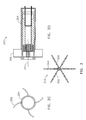
- Electrodes 212 may be formed of stainless steel in any conventional manner.
- electrode 212 of FIG. 3 includes 6 spikes on 3 mutually orthogonal axes. Spikes have sharp tips for penetration of fabric and tissue and rearward facing barbs to deter removal from the target.
- Projectile 200 maintains its stowed configuration while in cartridge 104. At a suitable distance from launch device 102, fins 262 move away from casing 206 to put projectile 200 in the in flight configuration. Translating element 222 is forced rearward during flight. Impact with the target (FIG. 4A) causes projectile 200 to conform to the impact configuration wherein electrodes 236 are deployed into the target and translating element 222 bounces rearward to dislodge plug 202. After plug 202 separates from casing 206, electrode 212 swings and/or bounces erratically on tether 214. After electrode 212 contacts the target, projectile 200 is in its fully deployed configuration (FIG. 4B) and delivery of the stimulus signal may begin.
- a projectile attaches at least one electrode by force of impact of the projectile against the target and attaches at least a second electrode by releasing the second electrode accompanied by a substantial portion of the mass of the entire projectile.
- projectile 500 of FIGs. 5-6 has four configurations: (1) a stowed configuration (FIGs. 5A-5B), where fins and electrodes are in storage locations and orientations; (2) an in flight configuration (FIGs. 5C and 5D); (3) an impact configuration after contact with the target (FIG. 6A); and (4) an electrode deployed configuration (FIG. 6B).
- Projectile 500 includes casing 502, four rear electrodes 504, four fins 506, battery 508, rear facing electrode 510, circuit assembly 512, front electrodes 514, electrode tether 516, cap release 518, and cap 522.
- Casing 502 provides an aerodynamic housing for components of projectile 500. Casing 502 may support one or more fins 506 for improving its flight characteristics. An alternate implementation omits fins 506 for reduced cost.
- casing 502 is made of a polymer such as NORYL® or ABS plastic and is shaped and/or dimensioned in a suitable fashion to be delivered by the desired launch device. Fins 506 may also be made of plastic and may include copper or steel springs and/or pins for causing movement toward or retaining the deployed position. Fins may provide drag for stabilization of the flight.
- Rear electrodes 504 are positioned away from casing 502 in flight by spring force.
- Battery 508 provides power source 134 for circuit assembly 512.
- Battery 508 may include one or more conventional cells.
- battery 508 is a conventional 1.5 volt (nominal) cell in a AAAA standard sized package.
- Battery 508 may be fixed to casing 502 in any conventional manner. The mass of battery 508 adds to the inertia of casing 502 for more effective impact of rear electrodes with the target.
- Front electrode assembly 530 includes rear facing electrode 510, front electrodes 514, and break-away tabs 520. Front electrode assembly 530 is fixed to casing 502 when projectile 500 is mounted in cartridge 104; and, is released after impact of projectile 500 with the target. In one implementation, break-away tabs 520 fix assembly 530 to casing 502. Rear facing electrode 510 is intended to impale a target's hand as the target reaches toward front electrode assembly 530 for instance intending to remove front electrodes 514 from contact with the target.
- Circuit assembly 512 performs functions analogous to circuit assembly 230 discussed above.
- Electrode tether 516 electrically connects front electrodes 514 and rear facing electrode 510 for cooperation in a stimulus signal delivery circuit as discussed above.
- Two or more conductors in tether 516 supply a stimulus signal from waveform generator 136 of circuit assembly 512 to: (a) front electrodes and/or to (b) rear facing electrode 510.
- tether 516 extends from storage in casing 502 to a length (e.g., about 12.7 to 45.7 cm (5 to 18 inches)) that assures suitable electrode spacing between deployable rear electrodes 504 and front electrodes 514.
- Tether 516 may include elastic material to improve the force of impact between rear electrodes 504 and the target.
- a cap release is a deformable (e.g., rubber) element that when crushed on impact imparts a separating force between a front electrode assembly and the remainder of a projectile.
- cap release 518 compresses along axis 501 to release casing 502 from front electrode assembly 530.
- inertia of casing 502 and/or battery 508 work against cap release 518 and/or cap 522 to fracture break-away tabs 520.
- Cap release 518 and/or cap 522 may store compression energy later released into casing 502 to urge casing 502 away from front electrode assembly 530, deploying tether 516 out of casing 502.
- At least one rear electrode 504 then makes contact with the target at a point at a distance from front electrodes 514.
- An alternate implementation of projectile 500 includes a translating ring.
- the translating ring slides inside casing 502 and along axis 501 to force deployment of rear electrodes 504 that remain stowed until after impact.
- Such a translating ring may urge front electrodes into the target.
- the tethered object (212 or 502) may fall by gravity and/or move away from the target by rebound energy. As the object reaches the end of the tether, it may fall back toward the target, much like a pendulum.
- An elastic tether may further enhance the approach of the object to the target.
- An elastic tether stores energy as it stretches, returning this energy into the object as it contracts, accelerating the object toward the target, and increasing the likelihood of an effective penetration of clothing and/or skin of the target. A distance between the front electrode(s) and the rear electrode(s) of 12 to 24 inches is preferred.
- a secondary propellant or mechanism propels the tethered object erratically until impact with the target.
- the secondary propellant or mechanism may include a small rocket motor.
- a projectile includes one or more deployable electrode arms each having one or more barbs.
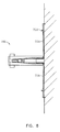
- projectile 700 of FIGs. 7-8 has four configurations: (1) a stowed configuration (FIGs. 7B and 7C), where fins and electrodes are in storage locations and orientations; (2) an in flight configuration (FIGs. 7A and 7C); (3) an impact configuration after contact with the target (analogous to FIG. 4A); and (4) an electrode deployed configuration (FIG. 8).
- Projectile 700 includes casing 702, four front electrodes 704, four fins 706, battery 708, circuit assembly 712, and release 710.
- Casing 702 provides an aerodynamic housing for components of projectile 700. Casing 702 may support one or more fins 706 for improving its flight characteristics. An alternate implementation omits fins 706 for reduced cost.
- casing 702 is made of a polymer such as NORYL® or ABS plastic and is shaped and/or dimensioned in a suitable fashion to be delivered by the desired launch device. Fins 706 may also be made of plastic and may include copper or steel springs and/or pins for causing movement toward or retaining the deployed position. Fins may provide drag for stabilization of the flight.
- Battery 708 and circuit assembly 712 operate in a manner analogous to battery 508 and circuit assembly 512 discussed above.
- release 710 After impact of projectile 700 and the target, release 710 releases a tab (not shown) on each electrode 704.
- release 710 includes a containment ring (not shown) that slides forward at the sudden deceleration of projectile 700. Translation of this ring releases each tab to permit each electrode to follow an arc away from axis 701 to a deployed position at or in front of the point of contact between projectile 700 and the target (depending on the shape of the surface around that point).
- Each electrode 704 may be urged along the arc by a torsion spring in each hinge 713. Electrodes 704 may be stowed in slots 726 formed in casing 702 along a length of projectile 700. When stowed, each torsion spring is compressed. The potential energy of the compressed torsion spring provides a propellant by which the electrodes 704 are forced out of slots 726 and into the target.
- Release 710 may include a hook 722 on each electrode and a slotted cylinder 724 that translates along axis 701 inside casing 702. Electrodes are retained when each hook 722 is in frictional contact with the slotted cylinder. Slotted cylinder 724 is forced rearward by the inertia of a projectile discharge from launch device 102 assuring frictional contact with hooks 722. After impact with the target, slotted cylinder 724 slides forward and releases each hook 722, deploying electrodes 704 as discussed above.
- projectile 700 In an alternate implementation of projectile 700, two of the four electrodes 704 are omitted. In a further alternate implementation, more than four electrodes are implemented symmetrically about axis 701. In addition, front electrodes of the type described above with reference to 236 and 514 are included in alternate projectiles having fixed mounting or springloaded mounting in the front of the projectile.
- a rear facing electrode may be added to any of projectiles 200, 700, and alternates of each discussed above.
- Deployment may use the forward momentum of the projectile to propel electrodes into contact with the target.
- a primary projectile carries several secondary projectiles.
- the forward momentum of the secondary projectiles after impact with the target may cause the secondary projectiles to deploy into the target.
- Secondary projectiles may be positioned in the rear portion of the primary projectile and housed in bores at an angle, (e.g., 45 degrees) to the axis of projectile flight.
- the configuration of the bores and the forward momentum vector forces each secondary projectile to deploy at the angle of the bore toward the target.
- Electrodes deployed in any manner from the secondary projectiles contact the target away from the one or more front electrodes of the primary projectile.
- Each secondary projectile or electrode may be tethered by a conductive wire to the primary or secondary projectile for delivering a stimulus signal.
- a propellant may also be used to propel the secondary projectiles or electrodes from within their respective bores.
- the primary projectile may include a pressurized gas or explosive charge which is activated after impact with the target. The propellant ejects each secondary projectile from its stowed location into the target.
- a method for increasing the effective spread between electrodes in contact with the target includes deploying multiple electrodes in one or more clusters or arrays. Multiple electrodes may have closer spacing to the point of projectile impact while still delivering the electrical charge to a greater surface area.
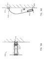
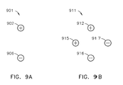
- muscular contractions were measured from two different configurations 901 and 911 as shown in FIGs. 9A and 9B.
- configuration 901 electrodes 902 and 906 were spaced four inches apart. Electrode 902 was connected to the positive terminal of a stimulation power supply. Electrode 906 was connected to the negative terminal of the power supply. In configuration 911, four electrodes were used. Electrode 912 was four inches from electrode 916; and electrode 915 was 10.2 cm (four inches) from electrode 917.
- Electrodes 912, 917, 916, and 915 formed a square centered about point 914. Points 904 and 914 may approximate the point of impact of a projectile. In other deployments the point of impact of the projectile is not material. Test results indicated configuration 911 was about 5% less effective (generated about 5% less muscle contraction) than configuration 901. It is believed that the lower effectiveness was the result of lower charge densities. While the greater number of electrodes delivered the charge to a greater total surface area, the total charge at each electrode was roughly cut in half, lowering the charge densities at the electrodes, and lowering the charge densities in the various current pathways through the body. This lower charge density resulted in fewer neurons being stimulated, and a lesser muscular response.
- a method for applying a stimulus signal to a plurality of electrodes includes, in any order: (a) selecting a pair of electrodes; (b) applying the stimulus signal to the selected pair; (c) monitoring the charge delivered into the target; (d) if the delivered charge is less than a limit, conclude that at least one of the selected electrodes is not sufficiently coupled to the target to form a stimulus signal delivery circuit; and (e) repeating the selecting, applying, and monitoring until a predetermined total charge is delivered.
- a microprocessor performing such a method may identify suitable electrodes in less than a millisecond such that the time to select the electrodes is not perceived by the target.
- after impact is understood to mean any instant of time after initial physical contact between a projectile and a target.
- the actions to be accomplished after impact are accomplished so soon after impact as to be perceived by the target as occurring simultaneously with impact.
Landscapes
- Engineering & Computer Science (AREA)
- General Engineering & Computer Science (AREA)
- Chemical & Material Sciences (AREA)
- Combustion & Propulsion (AREA)
- Remote Sensing (AREA)
- Life Sciences & Earth Sciences (AREA)
- Insects & Arthropods (AREA)
- Radar, Positioning & Navigation (AREA)
- Catching Or Destruction (AREA)
- Toys (AREA)
- Photoreceptors In Electrophotography (AREA)
- Aiming, Guidance, Guns With A Light Source, Armor, Camouflage, And Targets (AREA)
- Elimination Of Static Electricity (AREA)
- Magnetic Resonance Imaging Apparatus (AREA)
- Discharge Of Articles From Conveyors (AREA)
Claims (38)
- Dispositif (150) pour immobiliser une cible, le dispositif comprenant :une première électrode (236, 504) ;une deuxième électrode (212, 514) ;des moyens pour déployer la deuxième électrode depuis la première électrode, comprenant :(1) des moyens pour restreindre le déplacement de la deuxième électrode par rapport à la première électrode ; et(2) des moyens pour enlever la restriction de la deuxième électrode par rapport à la première électrode après que la première électrode entre en contact avec la cible, de sorte que la deuxième électrode s'éloigne initialement de la cible pour entrer en contact avec la cible à une distance de l'emplacement où la première électrode est entrée en contact avec la cible ; etdes moyens pour générer un signal de stimulus dans un circuit (136, 512) comprenant la première électrode et la deuxième électrode.
- Dispositif de la revendication 1, comprenant :une première portion comprenant la première électrode ; etune seconde portion comprenant la deuxième électrode et une longe (214, 516) qui maintient la communication électrique entre la première portion et la seconde portion.
- Dispositif de la revendication 2 dans lequel les moyens de restriction relient la première portion à la seconde portion pour transporter le dispositif d'immobilisation (150) en tant qu'unité.
- Dispositif de la revendication 2 dans lequel les moyens d'enlèvement comprennent un boîtier et un élément de translation qui se déplace par rapport au boîtier en réponse au choc du dispositif et de la cible pour libérer la seconde portion de la première portion.
- Dispositif de la revendication 2 dans lequel les moyens d'enlèvement comprennent une fixation qui est détachée en réponse au choc du dispositif et de la cible pour libérer la seconde portion de la première portion.
- Dispositif de la revendication 5 dans lequel la fixation comprend une patte de rupture (520).
- Dispositif de la revendication 2 dans lequel les moyens d'enlèvement comprennent un verrouillage qui est libéré en réponse au choc du dispositif et de la cible pour libérer la seconde portion de la première portion.
- Dispositif de la revendication 2 dans lequel la longe (214, 516) présente une élasticité pour effectuer un choc énergique de la deuxième électrode et de la cible.
- Dispositif de la revendication 2 dans lequel la seconde portion comprend en outre au moins une portion des moyens de génération d'un signal de stimulus.
- Dispositif de la revendication 9 dans lequel la masse totale de la seconde portion dépasse la masse totale de la première portion.
- Dispositif de la revendication 9 dans lequel la portion des moyens pour générer un signal de stimulus comprend une source d'alimentation (134).
- Dispositif de la revendication 2 dans lequel les moyens d'enlèvement utilisent l'énergie de choc du dispositif et de la cible pour libérer la seconde portion de la première portion.
- Dispositif de la revendication 2 dans lequel les moyens d'enlèvement redirige le moment de choc du dispositif et de la cible en mouvement de la seconde portion depuis la première portion.
- Dispositif de la revendication 2 dans lequel la première portion comprend en outre une troisième électrode pour entrer en contact avec la cible en conséquence du mouvement de la cible.
- Dispositif de la revendication 1 dans lequel les moyens de déploiement comprennent en outre un propulseur (120) qui propulse la deuxième électrode depuis la première électrode.
- Dispositif de la revendication 15 dans lequel le propulseur (120) propulse la deuxième électrode initialement dans une direction opposée à la cible.
- Dispositif de la revendication 1 dans lequel la deuxième électrode comprend un premier ardillon dirigé dans une première direction, un deuxième ardillon dirigé dans une deuxième direction, et un troisième ardillon dirigé dans une troisième direction.
- Dispositif de la revendication 17 dans lequel la première direction, la deuxième direction, et la troisième direction, sont mutuellement orthogonales.
- Projectile (132) comprenant le dispositif d'immobilisation de la revendication 1.
- Cartouche (104) comprenant le projectile de la revendication 19.
- Système (100) pour immobiliser une cible comprenant un projectile selon la revendication 19 ; et des moyens pour propulser le projectile vers une cible.
- Procédé pour immobiliser une cible utilisant un dispositif selon la revendication 1, ledit dispositif comprenant une première électrode, une deuxième électrode, un générateur de signal, et un appareil de déploiement d'électrode qui déploie la deuxième électrode, le procédé comprenant les étapes consistant à :restreindre le déplacement de la deuxième électrode par rapport à la première électrode ;enlever la restriction de la deuxième électrode par rapport à la première électrode après que la première électrode entre en contact avec la cible, de sorte que la deuxième électrode se déplace initialement depuis la cible pour entrer en contact avec la cible à une distance de l'emplacement où la première électrode est entrée en contact avec la cible ; etgénérer un signal de stimulus par l'intermédiaire du générateur de signal, la première électrode, et la deuxième électrode.
- Procédé de la revendication 22 dans lequel :le dispositif comprend en outre un boîtier et un bouchon qui dans une première position restreint le déplacement de la deuxième électrode dans le boîtier par rapport à la première électrode ; etl'enlèvement comprend la poussée du bouchon depuis la première position.
- Procédé de la revendication 23 dans lequel la production de l'appareil de déploiement comprend la production d'un élément de translation qui effectue une translation par rapport au boîtier pour repousser le bouchon depuis la première position.
- Procédé de la revendication 22 dans lequel la libération comprend le détachement d'une fixation.
- Procédé de la revendication 25 dans lequel le détachement de la fixation comprend le détachement d'une patte de rupture.
- Procédé de la revendication 22 dans lequel :la production du dispositif comprend en outre une étape consistant à produire un boîtier et un élément de translation qui effectue une translation par rapport au boîtier ; etl'enlèvement comprend une étape consistant à effectuer une translation effectuée par l'élément de translation.
- Procédé de la revendication 27 dans lequel la translation libère un verrouillage pour enlever la restriction.
- Procédé de la revendication 22 dans lequel l'enlèvement comprend la propulsion de la deuxième électrode depuis la première électrode.
- Procédé de la revendication 29 dans lequel la propulsion propulse la deuxième électrode initialement dans une direction opposée à la cible.
- Procédé de la revendication 22 dans lequel la production du dispositif comprend en outre la production d'une longe qui raccorde mécaniquement la deuxième électrode et la première électrode, la longe présentant une élasticité pour effectuer un choc énergique de la deuxième électrode et de la cible.
- Procédé de la revendication 22 dans lequel la deuxième électrode comprend un premier ardillon dirigé dans une première direction, un deuxième ardillon dirigé dans une deuxième direction, et un troisième ardillon dirigé dans une troisième direction.
- Procédé de la revendication 32 dans lequel la première direction, la deuxième direction, et la troisième direction, sont mutuellement orthogonales.
- Procédé de la revendication 22 dans lequel :la restriction du déplacement de la deuxième électrode par rapport à la première électrode restreint en outre le déplacement du générateur de signal par rapport à la première électrode ; etl'enlèvement de restriction permet à la deuxième électrode et au moins une portion du générateur de signal de se déplacer par rapport à la première électrode.
- Procédé de la revendication 34 dans lequel la masse de la deuxième électrode et la portion du générateur de signal dépassent la moitié de la masse totale du dispositif.
- Procédé de la revendication 34 dans lequel la portion du générateur de signal comprend une source d'alimentation.
- Procédé de la revendication 22 dans lequel l'enlèvement utilise l'énergie de choc du dispositif et de la cible.
- Procédé de la revendication 22 dans lequel l'enlèvement comprend la redirection du moment de choc du dispositif et de la cible en mouvement de la deuxième électrode.
Applications Claiming Priority (3)
| Application Number | Priority Date | Filing Date | Title |
|---|---|---|---|
| US50957703P | 2003-10-07 | 2003-10-07 | |
| US10/714,572 US7042696B2 (en) | 2003-10-07 | 2003-11-13 | Systems and methods using an electrified projectile |
| PCT/US2004/032981 WO2005084173A2 (fr) | 2003-10-07 | 2004-10-07 | Systemes et procedes faisant intervenir un projectile electrifie |
Publications (3)
| Publication Number | Publication Date |
|---|---|
| EP1671406A2 EP1671406A2 (fr) | 2006-06-21 |
| EP1671406A4 EP1671406A4 (fr) | 2007-01-03 |
| EP1671406B1 true EP1671406B1 (fr) | 2007-10-03 |
Family
ID=34396589
Family Applications (1)
| Application Number | Title | Priority Date | Filing Date |
|---|---|---|---|
| EP04821628A Not-in-force EP1671406B1 (fr) | 2003-10-07 | 2004-10-07 | Systemes et procedes faisant intervenir un projectile electrifie |
Country Status (9)
| Country | Link |
|---|---|
| US (1) | US7042696B2 (fr) |
| EP (1) | EP1671406B1 (fr) |
| JP (2) | JP4073466B2 (fr) |
| KR (2) | KR100843528B1 (fr) |
| AT (1) | ATE375024T1 (fr) |
| AU (1) | AU2004317013B2 (fr) |
| DE (1) | DE602004009330T2 (fr) |
| IL (1) | IL174777A (fr) |
| WO (1) | WO2005084173A2 (fr) |
Cited By (2)
| Publication number | Priority date | Publication date | Assignee | Title |
|---|---|---|---|---|
| RU2607701C2 (ru) * | 2012-09-24 | 2017-01-10 | Юрий Олегович Ладягин | Патрон ДЭШО и метательный заряд |
| WO2022047073A1 (fr) * | 2020-08-28 | 2022-03-03 | Axon Enterprise, Inc. | Pare-chocs extensible pour une électrode |
Families Citing this family (57)
| Publication number | Priority date | Publication date | Assignee | Title |
|---|---|---|---|---|
| US7736237B2 (en) | 2002-03-01 | 2010-06-15 | Aegis Industries, Inc. | Electromuscular incapacitation device and methods |
| US7042696B2 (en) * | 2003-10-07 | 2006-05-09 | Taser International, Inc. | Systems and methods using an electrified projectile |
| EP2328388B1 (fr) * | 2003-10-07 | 2014-04-23 | Taser International Inc. | Systèmes et procédés d'immobilisation |
| US7602597B2 (en) * | 2003-10-07 | 2009-10-13 | Taser International, Inc. | Systems and methods for immobilization using charge delivery |
| US7409912B2 (en) * | 2004-07-14 | 2008-08-12 | Taser International, Inc. | Systems and methods having a power supply in place of a round of ammunition |
| US7111559B1 (en) * | 2004-07-15 | 2006-09-26 | Maclachlan Edward K | Mobile electrical device for disabling a moving vehicle |
| WO2006135403A2 (fr) * | 2004-08-30 | 2006-12-21 | Zuoliang Chen | Projectile pour arme paralysant a distance |
| IL165489A0 (en) * | 2004-12-01 | 2006-01-15 | Odf Optronics Ltd | Smart arrow |
| US7421951B2 (en) * | 2004-12-01 | 2008-09-09 | Drexel University | Piezoelectric stun projectile |
| US20060254108A1 (en) * | 2005-04-20 | 2006-11-16 | Park Yong S | Electrical discharge immobilization weapon projectile having multiple deployed contacts |
| US8342098B2 (en) * | 2005-07-12 | 2013-01-01 | Security Devices International Inc. | Non-lethal wireless stun projectile system for immobilizing a target by neuromuscular disruption |
| US20080007887A1 (en) * | 2006-06-09 | 2008-01-10 | Massachusetts Institute Of Technology | Electrodes, devices, and methods for electro-incapacitation |
| US7905180B2 (en) | 2006-06-13 | 2011-03-15 | Zuoliang Chen | Long range electrified projectile immobilization system |
| US7984676B1 (en) | 2007-06-29 | 2011-07-26 | Taser International, Inc. | Systems and methods for a rear anchored projectile |
| US7856929B2 (en) | 2007-06-29 | 2010-12-28 | Taser International, Inc. | Systems and methods for deploying an electrode using torsion |
| JP5187936B2 (ja) * | 2007-09-20 | 2013-04-24 | 株式会社Ihiエアロスペース | 弾体 |
| US20090251311A1 (en) | 2008-04-06 | 2009-10-08 | Smith Patrick W | Systems And Methods For Cooperative Stimulus Control |
| US8261666B2 (en) * | 2008-10-26 | 2012-09-11 | Rakesh Garg | Charging holder for a non-lethal projectile |
| US7952850B1 (en) | 2008-12-30 | 2011-05-31 | Taser International, Inc. | Systems and methods for an electronic demotivator having a recovery switch |
| US8231474B2 (en) * | 2009-04-30 | 2012-07-31 | Aegis Industries, Inc. | Multi-stimulus personal defense device |
| TWI416061B (zh) * | 2009-07-23 | 2013-11-21 | Taser International Inc | 具有電流散佈電極之電子武器系統 |
| US8441771B2 (en) | 2009-07-23 | 2013-05-14 | Taser International, Inc. | Electronic weaponry with current spreading electrode |
| US8403672B2 (en) | 2009-10-21 | 2013-03-26 | Tim Odorisio | Training target for an electronically controlled weapon |
| US20110102964A1 (en) * | 2009-11-03 | 2011-05-05 | Ken Bass | Cartridge holder for an electroshock weapon |
| US9080840B2 (en) | 2010-06-30 | 2015-07-14 | Taser International, Inc. | Electronic weaponry with canister for electrode launch |
| US8587918B2 (en) * | 2010-07-23 | 2013-11-19 | Taser International, Inc. | Systems and methods for electrodes for insulative electronic weaponry |
| US9435619B1 (en) * | 2012-11-19 | 2016-09-06 | Yong S. Park | Propulsion assembly for a dart-based electrical discharge weapon |
| US9618303B2 (en) * | 2014-09-29 | 2017-04-11 | Conceived Innovations | Electro control hazing device (ECHD) |
| US10082361B2 (en) | 2015-03-15 | 2018-09-25 | Forsythe & Storms Technologies LLC | Portable wireless electrical weapon |
| JP2016214143A (ja) * | 2015-05-20 | 2016-12-22 | 毅 難波 | 有害獣電撃捕獲器 |
| USD815242S1 (en) | 2015-12-10 | 2018-04-10 | Aegis Industries, Inc. | Baton |
| US10036615B2 (en) * | 2016-03-25 | 2018-07-31 | Wrap Technologies, Inc. | Entangling projectile deployment system |
| US10107599B2 (en) * | 2016-03-25 | 2018-10-23 | Wrap Technologies, Inc. | Entangling projectiles and systems for their use |
| US9816789B1 (en) | 2016-08-31 | 2017-11-14 | Elwha Llc | Trajectory-controlled electro-shock projectiles |
| US9903691B1 (en) | 2016-08-31 | 2018-02-27 | Elwha Llc | Electro-shock projectile launcher |
| US10634461B2 (en) | 2017-06-24 | 2020-04-28 | Wrap Technologies, Inc. | Entangling projectiles and systems for their use |
| USD822785S1 (en) | 2017-09-29 | 2018-07-10 | Wrap Technologies, Inc. | Projectile casing |
| USD820940S1 (en) | 2017-09-29 | 2018-06-19 | Wrap Technologies, Inc. | Projectile launcher |
| WO2019079288A1 (fr) | 2017-10-18 | 2019-04-25 | Wrap Technologies, Inc. | Systèmes et procédés de génération de faisceaux de ciblage |
| AU2018385236B2 (en) | 2017-12-14 | 2021-12-09 | Axon Enterprise, Inc. | Systems and methods for an electrode for a conducted electrical weapon |
| AU2018410908B2 (en) * | 2018-03-01 | 2021-11-11 | Axon Enterprise, Inc. | Systems and methods for detecting a distance between a conducted electrical weapon and a target |
| US10852114B2 (en) | 2018-07-03 | 2020-12-01 | Wrap Technologies, Inc. | Adhesive-carrying entangling projectiles and systems for their use |
| US11371810B2 (en) | 2018-07-03 | 2022-06-28 | Wrap Technologies, Inc. | Seal-carrying entangling projectiles and systems for their use |
| EP3847412A4 (fr) * | 2018-09-07 | 2022-06-15 | NL Enterprises, LLC | Structure et lanceur de projectile non létal |
| US10890419B2 (en) | 2018-09-11 | 2021-01-12 | Wrap Technologies, Inc. | Systems and methods for non-lethal, near-range detainment of subjects |
| US11835320B2 (en) | 2018-09-11 | 2023-12-05 | Wrap Technologies, Inc. | Systems and methods for non-lethal, near-range detainment of subjects |
| US11920902B2 (en) | 2018-11-09 | 2024-03-05 | Convey Technology, Inc. | Pressure and heat conducted energy device and method |
| US10948269B2 (en) | 2018-12-04 | 2021-03-16 | Wrap Technologies Inc. | Perimeter security system with non-lethal detainment response |
| US20240019231A1 (en) * | 2019-02-25 | 2024-01-18 | The Secretary Of State For Defence | Device and method for mine disposal |
| US11280591B2 (en) * | 2019-09-03 | 2022-03-22 | Harkind Dynamics, LLC | Intelligent munition |
| FR3105395A1 (fr) * | 2019-12-24 | 2021-06-25 | Jean Angelidis | Projectile de neutralisation de cible par impulsion électrique, à deux parties séparables lors d’un tir et intégrant chacune un dard, les deux dards étant reliés entre eux par un fil électriquement conducteur alimenté par au moins un moyen de génération de haute tension logé dans l’une des parties. |
| FR3105393A1 (fr) * | 2019-12-24 | 2021-06-25 | Jean Angelidis | Projectile de neutralisation d’une cible par impulsion électrique, comprenant un corps avec deux dards en saillie et logeant au moins un moyen de génération de haute tension, destiné à appliquer une impulsion électrique HT à la cible à neutraliser. |
| US11156432B1 (en) | 2020-08-31 | 2021-10-26 | Wrap Techologies, Inc. | Protective coverings and related methods for entangling projectiles |
| US11761737B2 (en) | 2021-02-18 | 2023-09-19 | Wrap Technologies, Inc. | Projectile launching systems with anchors having dissimilar flight characteristics |
| US11555673B2 (en) | 2021-02-18 | 2023-01-17 | Wrap Technologies, Inc. | Projectile launching systems with anchors having dissimilar flight characteristics |
| US11852439B2 (en) | 2021-11-24 | 2023-12-26 | Wrap Technologies, Inc. | Systems and methods for generating optical beam arrays |
| US11510403B1 (en) * | 2021-12-14 | 2022-11-29 | GrillThink! LLC | Insect zapper gun with electrified projectile |
Family Cites Families (26)
| Publication number | Priority date | Publication date | Assignee | Title |
|---|---|---|---|---|
| CA981742A (en) * | 1970-05-14 | 1976-01-13 | John H. Cover (Jr.) | Weapon for immobilization and capture |
| US4253132A (en) | 1977-12-29 | 1981-02-24 | Cover John H | Power supply for weapon for immobilization and capture |
| US4982645A (en) * | 1990-01-23 | 1991-01-08 | Abboud Joseph G | Irritant ejecting stun gun |
| US5193048A (en) | 1990-04-27 | 1993-03-09 | Kaufman Dennis R | Stun gun with low battery indicator and shutoff timer |
| US5304211A (en) * | 1991-11-25 | 1994-04-19 | Behavior Research Institute | Apparatus for administering electrical aversive stimulus and associated method |
| US5457597A (en) | 1993-08-12 | 1995-10-10 | Rothschild; Zane | Electrical shocking apparatus |
| US5473501A (en) | 1994-03-30 | 1995-12-05 | Claypool; James P. | Long range electrical stun gun |
| US5654867A (en) | 1994-09-09 | 1997-08-05 | Barnet Resnick | Immobilization weapon |
| US5750918A (en) | 1995-10-17 | 1998-05-12 | Foster-Miller, Inc. | Ballistically deployed restraining net |
| US5898125A (en) | 1995-10-17 | 1999-04-27 | Foster-Miller, Inc. | Ballistically deployed restraining net |
| US5698815A (en) | 1995-12-15 | 1997-12-16 | Ragner; Gary Dean | Stun bullets |
| US5786546A (en) | 1996-08-29 | 1998-07-28 | Simson; Anton K. | Stungun cartridge |
| US5962806A (en) | 1996-11-12 | 1999-10-05 | Jaycor | Non-lethal projectile for delivering an electric shock to a living target |
| US5855426A (en) | 1997-03-21 | 1999-01-05 | Burns; Robert Lee | Combination flashlight-pyrotechnic signalling device launcher |
| US5831199A (en) | 1997-05-29 | 1998-11-03 | James McNulty, Jr. | Weapon for immobilization and capture |
| US5936183A (en) | 1997-12-16 | 1999-08-10 | Barnet Resnick | Non-lethal area denial device |
| US5841622A (en) | 1998-02-04 | 1998-11-24 | Mcnulty, Jr.; James F. | Remotely activated electrical discharge restraint device using biceps' flexion of the leg to restrain |
| US6053088A (en) | 1998-07-06 | 2000-04-25 | Mcnulty, Jr.; James F. | Apparatus for use with non-lethal, electrical discharge weapons |
| US6636412B2 (en) | 1999-09-17 | 2003-10-21 | Taser International, Inc. | Hand-held stun gun for incapacitating a human target |
| US6575073B2 (en) | 2000-05-12 | 2003-06-10 | Mcnulty, Jr. James F. | Method and apparatus for implementing a two projectile electrical discharge weapon |
| US6381894B1 (en) | 2000-08-29 | 2002-05-07 | The United States Of America As Represented By The Secretary Of The Navy | Bola launcher |
| US6543364B2 (en) | 2001-02-15 | 2003-04-08 | Scientific Applications & Research Associates | Less lethal multi-sensory distraction grenade |
| US6553913B1 (en) | 2001-04-03 | 2003-04-29 | The United States Of America As Represented By The Secretary Of The Navy | Projectile and weapon system providing variable lethality |
| AT411935B (de) | 2001-09-19 | 2004-07-26 | Oregon Ets Patentverwertung | Geschosshaube |
| US6679180B2 (en) * | 2001-11-21 | 2004-01-20 | Southwest Research Institute | Tetherless neuromuscular disrupter gun with liquid-based capacitor projectile |
| US7042696B2 (en) * | 2003-10-07 | 2006-05-09 | Taser International, Inc. | Systems and methods using an electrified projectile |
-
2003
- 2003-11-13 US US10/714,572 patent/US7042696B2/en not_active Expired - Lifetime
-
2004
- 2004-10-07 AT AT04821628T patent/ATE375024T1/de not_active IP Right Cessation
- 2004-10-07 WO PCT/US2004/032981 patent/WO2005084173A2/fr active IP Right Grant
- 2004-10-07 EP EP04821628A patent/EP1671406B1/fr not_active Not-in-force
- 2004-10-07 DE DE602004009330T patent/DE602004009330T2/de active Active
- 2004-10-07 KR KR1020067006773A patent/KR100843528B1/ko active IP Right Grant
- 2004-10-07 JP JP2006534303A patent/JP4073466B2/ja not_active Expired - Fee Related
- 2004-10-07 AU AU2004317013A patent/AU2004317013B2/en not_active Ceased
- 2004-10-07 KR KR1020077018526A patent/KR100859307B1/ko not_active IP Right Cessation
-
2006
- 2006-04-04 IL IL174777A patent/IL174777A/en active IP Right Grant
-
2007
- 2007-06-14 JP JP2007157292A patent/JP4681580B2/ja not_active Expired - Fee Related
Cited By (3)
| Publication number | Priority date | Publication date | Assignee | Title |
|---|---|---|---|---|
| RU2607701C2 (ru) * | 2012-09-24 | 2017-01-10 | Юрий Олегович Ладягин | Патрон ДЭШО и метательный заряд |
| WO2022047073A1 (fr) * | 2020-08-28 | 2022-03-03 | Axon Enterprise, Inc. | Pare-chocs extensible pour une électrode |
| US11566874B2 (en) | 2020-08-28 | 2023-01-31 | Axon Enterprise, Inc. | Expandable bumper for an electrode |
Also Published As
| Publication number | Publication date |
|---|---|
| EP1671406A2 (fr) | 2006-06-21 |
| KR20070091372A (ko) | 2007-09-10 |
| WO2005084173A2 (fr) | 2005-09-15 |
| AU2004317013B2 (en) | 2008-04-03 |
| AU2004317013A1 (en) | 2005-09-15 |
| ATE375024T1 (de) | 2007-10-15 |
| US20050073796A1 (en) | 2005-04-07 |
| JP2007292455A (ja) | 2007-11-08 |
| KR100843528B1 (ko) | 2008-07-03 |
| EP1671406A4 (fr) | 2007-01-03 |
| KR20060085666A (ko) | 2006-07-27 |
| US20050152087A2 (en) | 2005-07-14 |
| KR100859307B1 (ko) | 2008-09-19 |
| JP4681580B2 (ja) | 2011-05-11 |
| IL174777A (en) | 2010-11-30 |
| US7042696B2 (en) | 2006-05-09 |
| DE602004009330D1 (de) | 2007-11-15 |
| JP2007507687A (ja) | 2007-03-29 |
| JP4073466B2 (ja) | 2008-04-09 |
| DE602004009330T2 (de) | 2008-07-10 |
| WO2005084173A3 (fr) | 2005-11-17 |
| IL174777A0 (en) | 2006-08-20 |
Similar Documents
| Publication | Publication Date | Title |
|---|---|---|
| EP1671406B1 (fr) | Systemes et procedes faisant intervenir un projectile electrifie | |
| US7327549B2 (en) | Systems and methods for target impact | |
| US5698815A (en) | Stun bullets | |
| US20070019358A1 (en) | Immobilization weapon | |
| US7602597B2 (en) | Systems and methods for immobilization using charge delivery | |
| US20060187610A1 (en) | Electrical immobilization weapon | |
| US7057872B2 (en) | Systems and methods for immobilization using selected electrodes | |
| US7280340B2 (en) | Systems and methods for immobilization | |
| US7701692B2 (en) | Systems and methods for projectile status reporting | |
| CN100588059C (zh) | 使用带电射弹的系统和方法 | |
| EP1718134B1 (fr) | Systèmes et procédés d'immobilisation à l'aide d'électrodes sélectionnées |
Legal Events
| Date | Code | Title | Description |
|---|---|---|---|
| PUAI | Public reference made under article 153(3) epc to a published international application that has entered the european phase |
Free format text: ORIGINAL CODE: 0009012 |
|
| 17P | Request for examination filed |
Effective date: 20060331 |
|
| AK | Designated contracting states |
Kind code of ref document: A2 Designated state(s): AT BE BG CH CY CZ DE DK EE ES FI FR GB GR HU IE IT LI LU MC NL PL PT RO SE SI SK TR |
|
| RIN1 | Information on inventor provided before grant (corrected) |
Inventor name: NERHEIM, MAGNE, H. Inventor name: SMITH, PATRICK, W. |
|
| A4 | Supplementary search report drawn up and despatched |
Effective date: 20061205 |
|
| RIC1 | Information provided on ipc code assigned before grant |
Ipc: F41H 13/00 20060101ALI20061129BHEP Ipc: F42B 12/20 20060101ALI20061129BHEP Ipc: F42B 12/36 20060101ALI20061129BHEP Ipc: F42B 12/58 20060101ALI20061129BHEP Ipc: F42B 10/00 20060101ALI20061129BHEP Ipc: H01T 23/00 20060101AFI20060410BHEP Ipc: F42B 12/00 20060101ALI20061129BHEP Ipc: F42B 8/00 20060101ALI20061129BHEP Ipc: F42B 12/68 20060101ALI20061129BHEP Ipc: F42B 5/24 20060101ALI20061129BHEP Ipc: H05C 1/06 20060101ALI20061129BHEP |
|
| DAX | Request for extension of the european patent (deleted) | ||
| GRAP | Despatch of communication of intention to grant a patent |
Free format text: ORIGINAL CODE: EPIDOSNIGR1 |
|
| GRAS | Grant fee paid |
Free format text: ORIGINAL CODE: EPIDOSNIGR3 |
|
| GRAA | (expected) grant |
Free format text: ORIGINAL CODE: 0009210 |
|
| AK | Designated contracting states |
Kind code of ref document: B1 Designated state(s): AT BE BG CH CY CZ DE DK EE ES FI FR GB GR HU IE IT LI LU MC NL PL PT RO SE SI SK TR |
|
| REG | Reference to a national code |
Ref country code: GB Ref legal event code: FG4D |
|
| RIN1 | Information on inventor provided before grant (corrected) |
Inventor name: SMITH, PATRICK, W. Inventor name: NERHEIM, MAGNE, H. |
|
| REG | Reference to a national code |
Ref country code: CH Ref legal event code: EP |
|
| REG | Reference to a national code |
Ref country code: IE Ref legal event code: FG4D |
|
| REF | Corresponds to: |
Ref document number: 602004009330 Country of ref document: DE Date of ref document: 20071115 Kind code of ref document: P |
|
| NLV1 | Nl: lapsed or annulled due to failure to fulfill the requirements of art. 29p and 29m of the patents act | ||
| REG | Reference to a national code |
Ref country code: CH Ref legal event code: PL |
|
| PG25 | Lapsed in a contracting state [announced via postgrant information from national office to epo] |
Ref country code: CH Free format text: LAPSE BECAUSE OF FAILURE TO SUBMIT A TRANSLATION OF THE DESCRIPTION OR TO PAY THE FEE WITHIN THE PRESCRIBED TIME-LIMIT Effective date: 20071003 Ref country code: SE Free format text: LAPSE BECAUSE OF FAILURE TO SUBMIT A TRANSLATION OF THE DESCRIPTION OR TO PAY THE FEE WITHIN THE PRESCRIBED TIME-LIMIT Effective date: 20080103 Ref country code: ES Free format text: LAPSE BECAUSE OF FAILURE TO SUBMIT A TRANSLATION OF THE DESCRIPTION OR TO PAY THE FEE WITHIN THE PRESCRIBED TIME-LIMIT Effective date: 20080114 Ref country code: LI Free format text: LAPSE BECAUSE OF FAILURE TO SUBMIT A TRANSLATION OF THE DESCRIPTION OR TO PAY THE FEE WITHIN THE PRESCRIBED TIME-LIMIT Effective date: 20071003 Ref country code: NL Free format text: LAPSE BECAUSE OF FAILURE TO SUBMIT A TRANSLATION OF THE DESCRIPTION OR TO PAY THE FEE WITHIN THE PRESCRIBED TIME-LIMIT Effective date: 20071003 |
|
| PG25 | Lapsed in a contracting state [announced via postgrant information from national office to epo] |
Ref country code: PT Free format text: LAPSE BECAUSE OF FAILURE TO SUBMIT A TRANSLATION OF THE DESCRIPTION OR TO PAY THE FEE WITHIN THE PRESCRIBED TIME-LIMIT Effective date: 20080303 Ref country code: BG Free format text: LAPSE BECAUSE OF FAILURE TO SUBMIT A TRANSLATION OF THE DESCRIPTION OR TO PAY THE FEE WITHIN THE PRESCRIBED TIME-LIMIT Effective date: 20080103 Ref country code: MC Free format text: LAPSE BECAUSE OF NON-PAYMENT OF DUE FEES Effective date: 20071031 Ref country code: PL Free format text: LAPSE BECAUSE OF FAILURE TO SUBMIT A TRANSLATION OF THE DESCRIPTION OR TO PAY THE FEE WITHIN THE PRESCRIBED TIME-LIMIT Effective date: 20071003 |
|
| ET | Fr: translation filed | ||
| PG25 | Lapsed in a contracting state [announced via postgrant information from national office to epo] |
Ref country code: AT Free format text: LAPSE BECAUSE OF FAILURE TO SUBMIT A TRANSLATION OF THE DESCRIPTION OR TO PAY THE FEE WITHIN THE PRESCRIBED TIME-LIMIT Effective date: 20071003 |
|
| PG25 | Lapsed in a contracting state [announced via postgrant information from national office to epo] |
Ref country code: DK Free format text: LAPSE BECAUSE OF FAILURE TO SUBMIT A TRANSLATION OF THE DESCRIPTION OR TO PAY THE FEE WITHIN THE PRESCRIBED TIME-LIMIT Effective date: 20071003 Ref country code: CZ Free format text: LAPSE BECAUSE OF FAILURE TO SUBMIT A TRANSLATION OF THE DESCRIPTION OR TO PAY THE FEE WITHIN THE PRESCRIBED TIME-LIMIT Effective date: 20071003 |
|
| PLBE | No opposition filed within time limit |
Free format text: ORIGINAL CODE: 0009261 |
|
| STAA | Information on the status of an ep patent application or granted ep patent |
Free format text: STATUS: NO OPPOSITION FILED WITHIN TIME LIMIT |
|
| PG25 | Lapsed in a contracting state [announced via postgrant information from national office to epo] |
Ref country code: SK Free format text: LAPSE BECAUSE OF FAILURE TO SUBMIT A TRANSLATION OF THE DESCRIPTION OR TO PAY THE FEE WITHIN THE PRESCRIBED TIME-LIMIT Effective date: 20071003 Ref country code: RO Free format text: LAPSE BECAUSE OF FAILURE TO SUBMIT A TRANSLATION OF THE DESCRIPTION OR TO PAY THE FEE WITHIN THE PRESCRIBED TIME-LIMIT Effective date: 20071003 Ref country code: BE Free format text: LAPSE BECAUSE OF FAILURE TO SUBMIT A TRANSLATION OF THE DESCRIPTION OR TO PAY THE FEE WITHIN THE PRESCRIBED TIME-LIMIT Effective date: 20071003 |
|
| 26N | No opposition filed |
Effective date: 20080704 |
|
| PG25 | Lapsed in a contracting state [announced via postgrant information from national office to epo] |
Ref country code: IE Free format text: LAPSE BECAUSE OF NON-PAYMENT OF DUE FEES Effective date: 20071008 |
|
| PG25 | Lapsed in a contracting state [announced via postgrant information from national office to epo] |
Ref country code: GR Free format text: LAPSE BECAUSE OF FAILURE TO SUBMIT A TRANSLATION OF THE DESCRIPTION OR TO PAY THE FEE WITHIN THE PRESCRIBED TIME-LIMIT Effective date: 20080104 Ref country code: EE Free format text: LAPSE BECAUSE OF FAILURE TO SUBMIT A TRANSLATION OF THE DESCRIPTION OR TO PAY THE FEE WITHIN THE PRESCRIBED TIME-LIMIT Effective date: 20071003 |
|
| PG25 | Lapsed in a contracting state [announced via postgrant information from national office to epo] |
Ref country code: FI Free format text: LAPSE BECAUSE OF FAILURE TO SUBMIT A TRANSLATION OF THE DESCRIPTION OR TO PAY THE FEE WITHIN THE PRESCRIBED TIME-LIMIT Effective date: 20071003 |
|
| PG25 | Lapsed in a contracting state [announced via postgrant information from national office to epo] |
Ref country code: SI Free format text: LAPSE BECAUSE OF FAILURE TO SUBMIT A TRANSLATION OF THE DESCRIPTION OR TO PAY THE FEE WITHIN THE PRESCRIBED TIME-LIMIT Effective date: 20071003 |
|
| PG25 | Lapsed in a contracting state [announced via postgrant information from national office to epo] |
Ref country code: CY Free format text: LAPSE BECAUSE OF FAILURE TO SUBMIT A TRANSLATION OF THE DESCRIPTION OR TO PAY THE FEE WITHIN THE PRESCRIBED TIME-LIMIT Effective date: 20071003 |
|
| PG25 | Lapsed in a contracting state [announced via postgrant information from national office to epo] |
Ref country code: LU Free format text: LAPSE BECAUSE OF NON-PAYMENT OF DUE FEES Effective date: 20071007 |
|
| PG25 | Lapsed in a contracting state [announced via postgrant information from national office to epo] |
Ref country code: HU Free format text: LAPSE BECAUSE OF FAILURE TO SUBMIT A TRANSLATION OF THE DESCRIPTION OR TO PAY THE FEE WITHIN THE PRESCRIBED TIME-LIMIT Effective date: 20080404 Ref country code: TR Free format text: LAPSE BECAUSE OF FAILURE TO SUBMIT A TRANSLATION OF THE DESCRIPTION OR TO PAY THE FEE WITHIN THE PRESCRIBED TIME-LIMIT Effective date: 20071003 |
|
| PG25 | Lapsed in a contracting state [announced via postgrant information from national office to epo] |
Ref country code: IT Free format text: LAPSE BECAUSE OF NON-PAYMENT OF DUE FEES Effective date: 20071031 |
|
| REG | Reference to a national code |
Ref country code: FR Ref legal event code: PLFP Year of fee payment: 12 |
|
| REG | Reference to a national code |
Ref country code: FR Ref legal event code: PLFP Year of fee payment: 13 |
|
| REG | Reference to a national code |
Ref country code: FR Ref legal event code: PLFP Year of fee payment: 14 |
|
| REG | Reference to a national code |
Ref country code: FR Ref legal event code: PLFP Year of fee payment: 15 |
|
| PGFP | Annual fee paid to national office [announced via postgrant information from national office to epo] |
Ref country code: GB Payment date: 20211027 Year of fee payment: 18 Ref country code: DE Payment date: 20211027 Year of fee payment: 18 |
|
| PGFP | Annual fee paid to national office [announced via postgrant information from national office to epo] |
Ref country code: FR Payment date: 20211025 Year of fee payment: 18 |
|
| REG | Reference to a national code |
Ref country code: DE Ref legal event code: R119 Ref document number: 602004009330 Country of ref document: DE |
|
| GBPC | Gb: european patent ceased through non-payment of renewal fee |
Effective date: 20221007 |
|
| PG25 | Lapsed in a contracting state [announced via postgrant information from national office to epo] |
Ref country code: FR Free format text: LAPSE BECAUSE OF NON-PAYMENT OF DUE FEES Effective date: 20221031 Ref country code: DE Free format text: LAPSE BECAUSE OF NON-PAYMENT OF DUE FEES Effective date: 20230503 |
|
| PG25 | Lapsed in a contracting state [announced via postgrant information from national office to epo] |
Ref country code: GB Free format text: LAPSE BECAUSE OF NON-PAYMENT OF DUE FEES Effective date: 20221007 |