EP1670202B1 - Verfahren und Vorrichtung zur Spektrumverwaltung für Kommunikationskanäle mit Übersprechen - Google Patents
Verfahren und Vorrichtung zur Spektrumverwaltung für Kommunikationskanäle mit Übersprechen Download PDFInfo
- Publication number
- EP1670202B1 EP1670202B1 EP04292930A EP04292930A EP1670202B1 EP 1670202 B1 EP1670202 B1 EP 1670202B1 EP 04292930 A EP04292930 A EP 04292930A EP 04292930 A EP04292930 A EP 04292930A EP 1670202 B1 EP1670202 B1 EP 1670202B1
- Authority
- EP
- European Patent Office
- Prior art keywords
- ref
- communication channel
- victim
- channel
- tone
- Prior art date
- Legal status (The legal status is an assumption and is not a legal conclusion. Google has not performed a legal analysis and makes no representation as to the accuracy of the status listed.)
- Not-in-force
Links
Images


Classifications
-
- H—ELECTRICITY
- H04—ELECTRIC COMMUNICATION TECHNIQUE
- H04L—TRANSMISSION OF DIGITAL INFORMATION, e.g. TELEGRAPHIC COMMUNICATION
- H04L5/00—Arrangements affording multiple use of the transmission path
- H04L5/003—Arrangements for allocating sub-channels of the transmission path
- H04L5/0058—Allocation criteria
- H04L5/0064—Rate requirement of the data, e.g. scalable bandwidth, data priority
-
- H—ELECTRICITY
- H04—ELECTRIC COMMUNICATION TECHNIQUE
- H04B—TRANSMISSION
- H04B3/00—Line transmission systems
- H04B3/02—Details
- H04B3/32—Reducing cross-talk, e.g. by compensating
-
- H—ELECTRICITY
- H04—ELECTRIC COMMUNICATION TECHNIQUE
- H04L—TRANSMISSION OF DIGITAL INFORMATION, e.g. TELEGRAPHIC COMMUNICATION
- H04L5/00—Arrangements affording multiple use of the transmission path
- H04L5/003—Arrangements for allocating sub-channels of the transmission path
- H04L5/0044—Arrangements for allocating sub-channels of the transmission path allocation of payload
- H04L5/0046—Determination of how many bits are transmitted on different sub-channels
-
- H—ELECTRICITY
- H04—ELECTRIC COMMUNICATION TECHNIQUE
- H04L—TRANSMISSION OF DIGITAL INFORMATION, e.g. TELEGRAPHIC COMMUNICATION
- H04L5/00—Arrangements affording multiple use of the transmission path
- H04L5/003—Arrangements for allocating sub-channels of the transmission path
- H04L5/0058—Allocation criteria
- H04L5/006—Quality of the received signal, e.g. BER, SNR, water filling
-
- H—ELECTRICITY
- H04—ELECTRIC COMMUNICATION TECHNIQUE
- H04L—TRANSMISSION OF DIGITAL INFORMATION, e.g. TELEGRAPHIC COMMUNICATION
- H04L5/00—Arrangements affording multiple use of the transmission path
- H04L5/0001—Arrangements for dividing the transmission path
- H04L5/0003—Two-dimensional division
- H04L5/0005—Time-frequency
- H04L5/0007—Time-frequency the frequencies being orthogonal, e.g. OFDM(A), DMT
Definitions
- the present invention relates to a method for determining at least one operational transmit power S n k over a communication channel coupled to a disturbance causing transceiver, for at least one tone, said communication channel degrading one or more victim communication channels by cross-talk interferences.
- the selection of at least one reference victim communication channel for representing at least one reference for all victim communication channels which are degraded by cross-talk interferences from said communication channel is completed with the maximization of the data rate over said at least one reference victim communication channel under the constraint that the data rate over said communication channel achieves a target rate without exceeding an overall power constraint.
- This method therefore constitutes a different solution to the one proposed in the prior art since now the data rate of the at least one reference victim channel is maximized taking into account some constraints with respect to the data rate and the power over the individual communication channels coupled to the disturbance causing transceivers. It will be shown that this optimization problem not only will result in a maximum data rate over the at least one reference victim channel, but that at the same time also a near-optimal power spectrum on the individual communication channels coupled to the disturbance causing transceivers itself is obtained.
- the communication channel coupled to a disturbance causing transceiver is part of a plurality of communication channels associated to a plurality of disturbance causing transceivers and that the at least one reference victim channel is used in common for all communication channels of this plurality, a near-optimum solution for all these communication channels can be obtained, as was also the aim for the optimum method.
- a further characteristic feature of the present invention is set out in claim 2.
- Still another characteristic feature of the present invention is set out in claim 3.
- This equation allows to maximize the data rate of the at least one reference victim channel under the constraint that the data rate over the communication channel coupled to a disturber transceiver achieves its target rate without exceeding a power constraint.
- This equation can be solved in closed form since the partial derivation of this function to the individual power spectral density S k n , leads to a cubic polynomial with 3 roots for which closed form expressions exist. Each root has to be filled in in the overall cost function to select the optimal one. The value (of the three possible solutions) that maximizes the overall cost function will result in the optimal solution for that tone and that user.
- a further characteristic feature of the present invention is set out in claim 4.
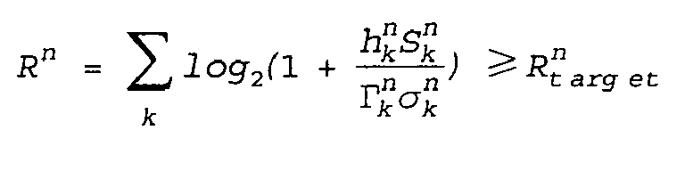
- the optimization of the above referred to function for all tones k allows to calculate the total data rate over a communication channel n in accordance with the formula as set out in claim 5 .
- This total data rate can in a next step be compared with the target rate, resulting in a possible adaptation of a first optimization variable.
- This update can easily be realized, for instance by means of standard bisection or gradient descent algorithms.
- the total power over the communication channel n can be obtained by summing the individual powers for each individual tone, as is set out in claim 6, which will subsequently be compared with the overall power budget for this channel. Again this comparison allows to update now a second optimization variable, which is also easily done by means of standard bisection or gradient descent algorithms.
- Claim 7 further describes that the method is an iterative method, i.e. several attempts are to be performed for selecting values of the two optimization variables and for solving the corresponding equation, until final convergence is obtained.
- Claim 8 further specifies that the equation is to be solved for each disturber line in the binder and that this is to be repeated until convergence. Typically two to three iterations over all the users are sufficient to achieve convergence.
- Claim 9 further specifies that the maximisation of the data rate over said at least one reference victim channel taking into account the two constraints as set out in claim 1, is performed taking into account an additional power spectrum constraint.
- S k , max n When such a power spectrum constraint S k , max n is applied, the 3 aforementioned roots together with the value of the spectrum constraint have to be filled in in the overall cost function, being the function as set out in claim 3.
- the value (of now four possible solutions) that maximizes the overall cost function will result in the optimal solution for that tone and that user.
- the invention relates as well to an apparatus for performing the described method and which is described in claims 10 to 18.
- Cross-talk is known to severely limit the transmission capabilities of communication channels. With the mass deployment of broadband communication channels via DSL lines or wireless interfaces, the influence of cross-talk on the transmission quality via these broadband channels even becomes more pronounced. While cross-talk can be avoided by applying expensive shielding techniques, another approach for diminishing its influence on the quality of the transmission is by applying spectrum management techniques. These techniques aim to calculate an optimum power allocation per line, taking into account all possible interferences and noise.
- a traditional approach to spectrum management consists of using spectral masks for each user, resulting in a flat power spectrum for each communication channel.
- this is typically -40dBm/Hz.
- the use of a flat PSD does not exploit the fact that cross-talk coupling varies significantly with frequency.
- it is a static approach, based upon worst case channel and cross-talk models to guarantee broad deployment. The result is an overly conservative design which leads to poor performance in terms of service reach and achievable data rate.
- Dynamic spectrum management techniques have been developed to overcome these problems related to the static spectrum management techniques. Among these dynamic spectrum management techniques iterative waterfilling and optimal spectrum management were discussed in the literature as well.
- the optimum spectrum management algorithm requires knowledge of all cross-talk channels and background noises for the channels to be optimized such as these belonging to one binder in DSL applications. This requires a multiple input, multiple output channel identification procedure which does not exist in currently deployed DSL. Due to the high level of co-ordination required between transceivers and the associated hardware changes that this would necessitate, MIMO channel identification may not be implemented for several years. This again limits the applicability of the optimum spectrum management algorithm.
- the method according to the present invention aims to provide a near-optimum solution, which is yet computationally solvable.
- the present technique is called autonomous spectrum balancing and will be explained now into more detail in conjunction with the figures.
- a key step used in the method is the provision of at least one reference victim channel for representing at least one reference victim for all victim communication channels which are degraded by cross-talk interferences from the channel for which the optimal power allocation is to be calculated.
- the victim communication channels consist of DSL lines coupled to transceivers denoted Victim 1 and Victim 2, both located in a central office CO.
- the disturbance generating transceivers are denoted Disturber 1 to Disturber n and are respectively coupled to the channels for which the power allocation is to be calculated, denoted L 1 to L n .
- the disturbance generating transceivers are located in a remote terminal, which are often coupled via an optical fiber, denoted OF, to this central office CO.
- OF optical fiber
- this configuration does not mean to be restrictive and the method is as well applicable for other configurations, i.e. disturbers in the central office and victims remotely deployed, or both disturbers and victims located at the same side.
- the victims correspond to the transceivers for which the performance is severely limited by interference from a particular disturber.
- one or more representative victims are either selected or determined and as such finally provided , in the form of at least one reference victim communication channel, denoted L ref in Fig. 1 .
- L ref the reference victim communication channel
- the reference victim transceiver, denoted "Ref victim” may be one of the existing victim transceivers or a fictitious one as depicted in Fig. 1 .
- several reference channels can be selected.
- the communication channel for which the power allocation is to be determined is denoted L n in Fig 1
- the power, per frequency bin or tone, which is to be determined for this channel is denoted s k n .
- h k ref the associated channel characteristic
- ⁇ k ref the associated reference background noise
- the cross talk x k ref , n between this channel L n and the reference victim channel L ref is to be provided , for this tone k.
- This cross talk is schematically depicted in Fig. 1 by the thin bowed arrow between communication channel L n and the reference victim L ref .
- the cross talk to be provided for the method can for instance be based on empirical cross-talk models and on an assumed distance between the reference victim transceiver and the transceiver n for which the power allocation is to be determined.
- the distance between the disturber transceiver and a base station can for instance be compared with the distance between the reference transceiver and the base station, upon which comparison such a cross-talk determination and provisioning may result.
- This cross talk may be the worst case cross talk, or be a realistic assumption of the present cross talk between the reference victim and the disturber channel.
- ⁇ k ref representing the SNR gap for the at least one reference victim channel to achieve a predefined bit error rate
- ⁇ k n representing the SNR gap for channel n to achieve a predefined bit error rate
- the SNR gap is a function of the predefined bit error rate and the line code, which is e.g. quadrature amplitude modulation in DSL.
- the gap indicates the efficiency of the transmission method compared to the best possible performance of the communication channel.
- An optimum line code with a gap equal to one achieves the maximum throughput of a channel, the so-called channel capacity.
- the gap is typically in the range of 10 dB to 15 dB.
- J s k n log 2 ⁇ 1 + h k ref ⁇ s k ref ⁇ k ref ⁇ x k ref , n ⁇ s k n + ⁇ k ref + w n ⁇ log 2 ⁇ 1 + h k n + s k n ⁇ k n ⁇ ⁇ k n ⁇ ⁇ n ⁇ s k n
- the first term is a representation of the number of bits allocated to tone k for the at least one reference victim channel based on the Shannon-Hartley theorem, taking into account the transmission efficiency throughput
- the second term is related to the number of bits allocated to tone k for the disturber
- the third term is related to a constraint on the overall power that the disturber is allowed to transmit.
- the second term in equation (1) is in accordance with the Shannon-Hartley theorem taking into account the transmission efficiency ⁇ k n , but multiplied by a certain weight W n constituting a first optimization variable.
- the third term in equation (1) represents the power allocated to tone k, multiplied with a second weight or optimization variable ⁇ n .
- Optimizing the function J s k n therefore breaks down to maximizing the data rate R ref over the reference victim channel under two constraints : a first one related to the target data rate over the disturber channel itself and a second one relating to the power over this disturber channel.
- the first optimization variable w n is adapted such that, whenever R n is smaller than its target value, w n is increased, while whenever R n is larger than the target data rate, w n is decreased.
- This update of W n can easily be done by means of e.g. steepest descent or standard bisection algorithms.
- the second optimization variable ⁇ n is to be updated via the second constraint that the total overall power for the RT line n, denoted as P n has to be smaller than a maximum value denoted (P n max ), which corresponds to the overall power budget allocatable to that channel.
- P n max a maximum value denoted (P n max )
- ⁇ n is such that, whenever P n is smaller than the overall power budget, ⁇ n is decreased, while whenever P n is larger than the overall power budget, ⁇ n is increased. Again this update can easily be done by means of standard bisection or gradient descent algorithms.
- the second optimization variable may be updated before the first variable.
- This third constraint relates to a power spectrum constraint S n k ⁇ S n k,max for the disturber line under consideration, and it guarantees that, in case a solution for maximizing the function J s k n is found for which the cost is lower than the solution found in case s k , max n would be filled in into equation (1), the latter s k , max n is used as the solution.
- Fig. 2 The complete sequence of steps to be followed in case of one reference victim channel is selected, is depicted in Fig. 2 . It is to be remarked that therein a variant of the method is shown wherein first the first optimization variable is adapted, being followed by the adaptation of the second. As already set out in a previous paragraph, this sequence may as well be reversed.
- Fig. 2 also shows the third constraint related to the additional power spectrum constraint (S n k,max ), as an option.
- each RT line n only needs to have knowledge of its own measured channel, its own measured background noise, the settings of the common reference line and its cross talk coupling model to the reference line, which is typically based on the common CO-RT distance. Therefore, this technique is, unlike optimal spectrum management , autonomous. Due to the closed form solution of equation (1), the method is computationally less complex than the exhaustive search procedure required by the optimal spectrum management technique. Since for DSL embodiments, the protection of a worst case reference victim also protects all other DSL-victims in the same binder, the power allocation results in near-optimal performance.
- the techniques have application for wireless transmission and for DSL, more in particular CO deployed ADSL, RT deployed ADSL and RT deployed VDSL/ADSL+ when legacy ADSL systems must be protected.
- the techniques may give significant gains over traditional static spectrum management where RT deployed VDSL is prohibited from transmitting in the ADSL band.
- the result is a simple, autonomous spectrum balancing method applicable to CO and RT deployed DSL.
- the scheme is dynamic in nature, highly flexible and gives significant gains over both static spectrum management and iterative waterfilling: according to Fig. 3 with 1 Mbps service on the CO ADSL, RT ADSL achieves 3.2 Mbps with Iterative Waterfilling and 7.3 Mbps with optimal spectrum balancing and with the proposed scheme.
- FIG. 4 An apparatus A adapted to perform the described method is depicted in Fig. 4 . It contains a means S for provision the necessary starting data such as L ref , L ⁇ 1 Vietnamese ⁇ Ln .. ⁇ ⁇ k ref , ⁇ k n , S k ref h k n h k ref ⁇ ⁇ k n ⁇ ⁇ k ref x k ref , n , R n taraet , P n max , S k max which can be directly received via an interface, denoted IF1 and incorporated in S, from an operator or from other devices such as from a central network controller via a similar interface. In case all data are provided, e.g.
- S merely serves as an interface to a calculating means C.
- S is further adapted to calculate from higher level network topology information such as the location of all transceivers and channels and/or the distance between them, the noise and cross talk models applied etc, which are received from a central network controller or an operator via IF1, specific sets of victims and associated data.
- startdata are provided by S to a calculating means C which will subsequently perform the calculation of the power spectral densities for the disturber channels.
- a memory M is placed in between S and C, but memory may as well be incorporated within the calculating means C or within S itself.
- the calculating means C is then adapted to determine the power to be allocated to each of the disturber transceivers, in accordance with the method which was explained in the previous paragraphs. C will provide these power spectral density results s k n via a second interface IF2 again to the network, for instance to the different transceivers themselves, or to a central network management device which will subsequently provide the results to the individual transceivers.
- Such an apparatus A may therefore be part of a central office transceiver, implemented as part of the software running on the processor chips, or as standalone software on a server. However the apparatus may also be part of a transceiver at the customer premises, either implemented in hardware or software. Alternatively the apparatus A may also be part of a stand-alone device adapted to communicate, with the operator or a central network management device on one hand and with the different transceivers on the other hand. Again also here implementations both in hardware and software are possible.
Claims (18)
- Verfahren zum Bestimmen mindestens einer Betriebssendeleistung Sn k über einen Kommunikationskanal Ln, der mit einem Störung verursachenden Transceiver n für mindestens einen Ton k gekoppelt ist, wobei der Kommunikationskanal Ln Teil einer Vielzahl von Kommunikationskanälen L1, ..., Ln ist, die mit einer Vielzahl von Störung verursachenden Transceivern 1, ..., n gekoppelt sind,
dadurch gekennzeichnet, daß das Verfahren die Schritte umfaßt:- Bereitstellen mindestens eines Referenzopferkommunikationskanals Lref zum Darstellen mindestens eines Referenzopfers für alle Opferkommunikationskanäle, die durch Nebensprechstörungen vom Kommunikationskanal Ln beeinträchtigt werden,- Maximieren der Datenrate Rref über mindestens einen Referenzopferkommunikationskanal Lref unter der Einschränkung, daß die Datenrate über den Kommunikationskanal Ln eine Zielrate Rn target erreicht, ohne daß die Gesamtleistung Pn auf dem Kommunikationskanal Ln eine Leistungsbeschränkung Pn max übersteigt, die dem Gesamtleistungbudget entspricht, das dem Kommunikationskanal Ln zuteilbar ist,und in welchem mindestens ein Referenzopferkommunikationskanal Lref gemeinsam für alle Kommunikationskanäle der Vielzahl verwendet wird. - Verfahren nach Anspruch 1, in welchem die Vielzahl der Kommunikationskanäle den in einem gemeinsamen Verbinder (B) gebündelten Leitern entspricht.
- Verfahren nach Anspruch 1, in welchem der Schritt des Maximierens der Datenrate Rref über mindestens einen Referenzopferkommunikationskanal Lref die Einschränkungen berücksichtigt, die durch Maximieren der folgenden Funktion


 wn - erste Optimierungsvariable für die Leitung nλn - zweite Optimierungsvariable für die Leitung n

- Verfahren nach Anspruch 3, in welchem der Schritt des Optimierens der Gleichung bezüglich der Leistungsspektraldichte

- Verfahren nach Anspruch 4, in welchem nach den Optimierungsschritten das Aktualisieren der ersten Optimierungsvariable wn folgt, so daß die Einschränkung, daß die Datenrate Rn über dem Kommunikationskanal Ln eine Zielrate

- Verfahren nach Anspruch 4, in welchem nach den Optimierungsschritten das Aktualisieren der zweiten Optimierungsvariablen λn folgt, so daß die Gesamtleistung Pn auf dem Kommunikationskanal Ln mit der Leistungseinschränkung Pn max durch folgende Gleichung übereinstimmt:

- Verfahren nach jedem der vorhergehenden Ansprüche 4 bis 6, in welchem die Schritte, wie in den Ansprüchen 4 bis 6 dargelegt, wiederholt werden, bis Übereinstimmung erhalten wird.
- Verfahren nach jedem der Ansprüche 1 bis 7, in welchem die Schritte, wie in den Ansprüchen 3 bis 7 dargelegt, über alle Kommunikationskanäle der Vielzahl L1, ..., Ln iteriert werden, bis Übereinstimmung erhalten wird.
- Verfahren nach jedem der vorhergehenden Ansprüche 1 bis 8, in welchem die Datenrate Rref über mindestens einen Referenzopferkommunikationskanal Lref unter Berücksichtigung einer zusätzlichen Leistungsspektrumseinschränkung Sn k,max maximiert wird.
- Vorrichtung (A) zum Bestimmen mindestens einer Betriebssendeleistung Sn k über einen Kommunikationskanal Ln, der mit einem Störung verursachenden Transceiver n für mindestens einen Ton k gekoppelt ist, wobei der Kommunikationskanal Ln Teil einer Vielzahl von Kommunikationskanälen L1, ..., Ln ist, die mit einer Vielzahl von Störung verursachenden Transceivern 1, ..., n gekoppelt sind, wobei die Vorrichtung gekennzeichnet ist durch
Mittel (S) zum Bereitstellen mindestens eines Referenzopferkommunikationskanals Lref zum Darstellen mindestens eines Referenzopfers für alle Opferkommunikationskanäle, die durch Nebensprechstörungen vom Kommunikationskanal Ln beeinträchtigt werden, und in welcher mindestens ein Referenzopferkommunikationskanal Lref gemeinsam für alle Kommunikationskanäle der Vielzahl verwendet wird, wobei mindestens ein Referenzopferkommunikationskanal an Berechnungsmittel (C) zum Maximieren der Datenrate Rref über mindestens einen Referenzopferkommunikationskanal Lref unter der Einschränkung bereitgestellt wird, daß die Datenrate über den Kommunikationskanal Ln eine Zielrate Rn target erreicht, ohne daß die Gesamtleistung Pn auf dem Kommunikationskanal Ln eine Leistungsbeschränkung Pn max übersteigt, die dem Gesamtleistungsbudget entspricht, das dem Kommunikationskanal Ln zuteilbar ist. - Vorrichtung nach Anspruch 10, in welcher die Vielzahl der Kommunikationskanäle den in einem gemeinsamen Verbinder (B) gebündelten Leitern entspricht.
- Vorrichtung (A) nach Anspruch 10, in welcher die Berechnungsmittel (C) außerdem angepaßt sind, um die Datenrate des mindestens einen Referenzopferkommunikationskanals Lref unter Berücksichtigung der Einschränkungen durch Maximieren der folgenden Funktion


 wn - erste Optimierungsvariable für die Leitung nλ n - zweite Optimierungsvariable für die Leitung n

- Vorrichtung (A) nach Anspruch 12, in welcher die Berechnungsmittel (C) außerdem angepaßt sind, um die Gleichung für alle Töne zu optimieren.
- Vorrichtung (A) nach Anspruch 13, in welcher die Berechnungsmittel (C) außerdem angepaßt sind, um die erste Optimierungsvariable wn zu aktualisieren, so daß die Einschränkung, daß die Datenrate Rn über dem Kommunikationskanal Ln eine Zielrate


- Vorrichtung (A) nach Anspruch 13, in welcher die Berechnungsmittel (C) außerdem angepaßt sind, um die zweite Optimierungsvariable λn zu aktualisieren, so daß die Gesamtleistung Pn auf dem Kommunikationskanal Ln mit der Leistungseinschränkung Pn max durch folgende Gleichung übereinstimmt:

- Vorrichtung (A) nach jedem der vorhergehenden Ansprüche 13 bis 15, in welcher die Berechnungsmittel (C) außerdem angepaßt sind, um die Optimierungen und Aktualisierungen zu wiederholen, bis die Übereinstimmung erhalten wird.
- Vorrichtung (A) nach jedem der vorhergehenden Ansprüche 10 bis 16, in welcher die Berechnungsmittel (C) außerdem angepaßt sind, um die Optimierungen und Aktualisierungen durchzuführen, wie in den Ansprüchen 12 bis 16 dargelegt ist, iterativ für alle Kommunikationskanäle der Vielzahl L1, ..., Ln, bis Übereinstimmung erhalten wird.
- Vorrichtung nach jedem der vorhergehenden Ansprüche 10 bis 17, in welcher die Berechnungsmittel (C) außerdem angepaßt sind, um die Datenrate Rref über mindestens einen Referenzopferkommunikationskanal Lref unter Berücksichtigung einer zusätzlichen Leistungsspektrumseinschränkung Sn k,max zu maximieren.
Priority Applications (5)
| Application Number | Priority Date | Filing Date | Title |
|---|---|---|---|
| EP04292930A EP1670202B1 (de) | 2004-12-08 | 2004-12-08 | Verfahren und Vorrichtung zur Spektrumverwaltung für Kommunikationskanäle mit Übersprechen |
| AT04292930T ATE403321T1 (de) | 2004-12-08 | 2004-12-08 | Verfahren und vorrichtung zur spektrumverwaltung für kommunikationskanäle mit übersprechen |
| DE602004015483T DE602004015483D1 (de) | 2004-12-08 | 2004-12-08 | Verfahren und Vorrichtung zur Spektrumverwaltung für Kommunikationskanäle mit Übersprechen |
| US11/295,614 US7782748B2 (en) | 2004-12-08 | 2005-12-07 | Power spectrum control method for communication channels limited by disturbers and apparatus for performing such a method |
| CN2005101302866A CN1801675B (zh) | 2004-12-08 | 2005-12-08 | 用于受干扰器限制的通信信道的功率谱控制方法及装置 |
Applications Claiming Priority (1)
| Application Number | Priority Date | Filing Date | Title |
|---|---|---|---|
| EP04292930A EP1670202B1 (de) | 2004-12-08 | 2004-12-08 | Verfahren und Vorrichtung zur Spektrumverwaltung für Kommunikationskanäle mit Übersprechen |
Publications (2)
| Publication Number | Publication Date |
|---|---|
| EP1670202A1 EP1670202A1 (de) | 2006-06-14 |
| EP1670202B1 true EP1670202B1 (de) | 2008-07-30 |
Family
ID=34931589
Family Applications (1)
| Application Number | Title | Priority Date | Filing Date |
|---|---|---|---|
| EP04292930A Not-in-force EP1670202B1 (de) | 2004-12-08 | 2004-12-08 | Verfahren und Vorrichtung zur Spektrumverwaltung für Kommunikationskanäle mit Übersprechen |
Country Status (5)
| Country | Link |
|---|---|
| US (1) | US7782748B2 (de) |
| EP (1) | EP1670202B1 (de) |
| CN (1) | CN1801675B (de) |
| AT (1) | ATE403321T1 (de) |
| DE (1) | DE602004015483D1 (de) |
Families Citing this family (12)
| Publication number | Priority date | Publication date | Assignee | Title |
|---|---|---|---|---|
| EP1876784A1 (de) * | 2006-07-05 | 2008-01-09 | Ftw. Forschungszentrum Telekommunikation Wien Betriebs GmbH | Verfahren zum Optimieren der Bitratenkapazität von Teilnehmeranschlussen |
| US8295151B2 (en) | 2007-03-23 | 2012-10-23 | Telefonaktiebolaget Lm Ericsson (Publ) | Method central unit, and modem in a digital subscriber line network |
| US7843990B2 (en) * | 2007-04-09 | 2010-11-30 | Alcatel-Lucent Usa Inc. | Determining a channel matrix by measuring interference |
| US7646778B2 (en) * | 2007-04-27 | 2010-01-12 | Cisco Technology, Inc. | Support of C-tagged service interface in an IEEE 802.1ah bridge |
| US8830812B2 (en) | 2007-08-31 | 2014-09-09 | Alcatel Lucent | Optimizing precoder settings using average SINR reports for groups of tones |
| US7830978B2 (en) * | 2007-08-31 | 2010-11-09 | Alcatel Lucent | Determining channel matrices by correlated transmissions to different channels |
| BRPI0823226A2 (pt) * | 2008-11-27 | 2015-07-07 | Ericsson Telefon Ab L M | Metodo e sistema para gerenciar recursos de transmissao em um sistema de comunicacao digital |
| US8665932B2 (en) | 2009-01-30 | 2014-03-04 | Futurewei Technologies, Inc. | Low complexity technique for digital subscriber line (DSL) power control |
| US8811600B2 (en) | 2009-03-31 | 2014-08-19 | Futurewei Technologies, Inc. | Optimizing the transmit power spectrum density (PSD) of a remotely deployed line to ensure spectral compatibility |
| WO2012126415A2 (zh) * | 2012-05-04 | 2012-09-27 | 华为技术有限公司 | 一种信号发送方法、通信设备及系统 |
| EP3694112B1 (de) * | 2014-03-11 | 2022-09-14 | Intel Germany GmbH & Co. KG | Kommunikationsgeräte , systeme und verfahren |
| CN108988980A (zh) * | 2017-05-31 | 2018-12-11 | 深圳世纪天成通讯设备开发有限公司 | 一种频率时隙发射管理方法及系统 |
Family Cites Families (19)
| Publication number | Priority date | Publication date | Assignee | Title |
|---|---|---|---|---|
| DE4032067A1 (de) * | 1990-10-10 | 1992-04-16 | Standard Elektrik Lorenz Ag | Leitungseinrichtung zur kompensation von nebensprechen |
| US6647058B1 (en) * | 1997-06-23 | 2003-11-11 | Paradyne Corporation | Performance customization system and process for optimizing XDSL performance |
| US6144696A (en) * | 1997-12-31 | 2000-11-07 | At&T Corp. | Spread spectrum bit allocation algorithm |
| SE9900788L (sv) * | 1998-11-21 | 2000-05-22 | Telia Ab | Förbättringar av, eller med avseende på, VDSL- transmissionssystem |
| US6978015B1 (en) * | 1999-11-11 | 2005-12-20 | Tokyo Electron Limited | Method and apparatus for cooperative diagnosis of impairments and mitigation of disturbers in communication systems |
| US20070047733A1 (en) * | 1999-12-15 | 2007-03-01 | Gordon Bremer | System and Method for Premises End Crosstalk Compensation |
| US6393052B2 (en) * | 2000-02-17 | 2002-05-21 | At&T Corporation | Method and apparatus for minimizing near end cross talk due to discrete multi-tone transmission in cable binders |
| US7158563B2 (en) * | 2001-06-01 | 2007-01-02 | The Board Of Trustees Of The Leland Stanford Junior University | Dynamic digital communication system control |
| CA2454239A1 (en) * | 2001-07-31 | 2003-02-13 | Telcordia Technologies, Inc. | Improved crosstalk identification for spectrum management in broadband telecommunications systems |
| ATE413736T1 (de) * | 2001-10-03 | 2008-11-15 | Alcatel Lucent | Verfahren und vorrichtung zum messen des übersprechens in einem xdsl-netz |
| US7164764B2 (en) * | 2002-11-07 | 2007-01-16 | Solarflare Communications, Inc. | Method and apparatus for precode crosstalk mitigation |
| DE60316544T2 (de) | 2003-06-25 | 2008-07-03 | Alcatel Lucent | Leistungssteuerungsverfahren für ein fernbedienbaren Kommunikationsdienst |
| US7315592B2 (en) * | 2003-09-08 | 2008-01-01 | Aktino, Inc. | Common mode noise cancellation |
| US7302379B2 (en) * | 2003-12-07 | 2007-11-27 | Adaptive Spectrum And Signal Alignment, Inc. | DSL system estimation and parameter recommendation |
| US7274734B2 (en) * | 2004-02-20 | 2007-09-25 | Aktino, Inc. | Iterative waterfiling with explicit bandwidth constraints |
| US7187766B2 (en) * | 2004-02-20 | 2007-03-06 | Adc Incorporated | Methods and systems for compensating for alien crosstalk between connectors |
| US7593458B2 (en) * | 2004-05-18 | 2009-09-22 | Adaptive Spectrum And Signal Alignment, Inc. | FEXT determination system |
| US20050259692A1 (en) * | 2004-05-19 | 2005-11-24 | Zerbe Jared L | Crosstalk minimization in serial link systems |
| US20060029148A1 (en) * | 2004-08-06 | 2006-02-09 | Tsatsanis Michail K | Method and apparatus for training using variable transmit signal power levels |
-
2004
- 2004-12-08 AT AT04292930T patent/ATE403321T1/de not_active IP Right Cessation
- 2004-12-08 DE DE602004015483T patent/DE602004015483D1/de active Active
- 2004-12-08 EP EP04292930A patent/EP1670202B1/de not_active Not-in-force
-
2005
- 2005-12-07 US US11/295,614 patent/US7782748B2/en not_active Expired - Fee Related
- 2005-12-08 CN CN2005101302866A patent/CN1801675B/zh not_active Expired - Fee Related
Also Published As
| Publication number | Publication date |
|---|---|
| CN1801675B (zh) | 2012-04-11 |
| ATE403321T1 (de) | 2008-08-15 |
| CN1801675A (zh) | 2006-07-12 |
| US7782748B2 (en) | 2010-08-24 |
| DE602004015483D1 (de) | 2008-09-11 |
| US20060153178A1 (en) | 2006-07-13 |
| EP1670202A1 (de) | 2006-06-14 |
Similar Documents
| Publication | Publication Date | Title |
|---|---|---|
| US7782748B2 (en) | Power spectrum control method for communication channels limited by disturbers and apparatus for performing such a method | |
| US10938427B2 (en) | Dynamic digital communication system control | |
| Papandriopoulos et al. | Low-complexity distributed algorithms for spectrum balancing in multi-user DSL networks | |
| EP1492261B1 (de) | Leistungssteuerungsverfahren für ein fernbedienbaren Kommunikationsdienst | |
| Tan et al. | Spectrum management in multiuser cognitive wireless networks: Optimality and algorithm | |
| JP5744746B2 (ja) | マルチキャリアシステムにおける電力割振りのための方法および装置 | |
| US9425858B2 (en) | UPBO for vectored DSL | |
| US20070274404A1 (en) | Method for distributed spectrum management of digital communications systems | |
| US8009574B2 (en) | Power level settings for transmission lines | |
| Guenach et al. | Power optimization in vectored and non-vectored G. fast transmission | |
| Wolkerstorfer et al. | Dynamic spectrum management for energy-efficient transmission in DSL | |
| Tsiaflakis et al. | An efficient search algorithm for the Lagrange multipliers of optimal spectrum balancing in multi-user xDSL systems | |
| Chan et al. | Joint multiuser detection and optimal spectrum balancing for digital subscriber lines | |
| Chowdhery et al. | Dynamic spectrum management for upstream mixtures of vectored & non-vectored DSL | |
| Whiting et al. | DSL crosstalk coefficient acquisition using SNR feedback | |
| Lindqvist et al. | Impact of crosstalk channel estimation on the DSM performance for DSL networks | |
| Sharma et al. | Reducing near–far problem in a vdsl network with modified iwf algorithm by using fixed spectral mask yielding improved data rate of near end user | |
| Monteiro et al. | An algorithm for improved stability of DSL networks using spectrum balancing | |
| Cendrillon et al. | Method and apparatus for spectrum management for communication channels with crosstalk | |
| Forouzan et al. | Price of Fairness in Digital Subscriber Line Systems Using Dynamic Spectrum Management | |
| Sharma et al. | Reducing Near–Far Problem in a VDSL Network with Modified IWF Algorithm by Using Adaptive Spectral Mask Yielding Improved Data Rate of Near End Users | |
| Sharma et al. | A novel technique to reduce Near-Far problem in multi-user VDSL network | |
| Vangorp et al. | Downstream power backoff in CO/RT-deployed xDSL networks | |
| Klügel et al. | Iterative waterfilling and multi-channel standard interference | |
| Verdyck et al. | Unequal error protection in rate adaptive spectrum management for digital subscriber line systems |
Legal Events
| Date | Code | Title | Description |
|---|---|---|---|
| PUAI | Public reference made under article 153(3) epc to a published international application that has entered the european phase |
Free format text: ORIGINAL CODE: 0009012 |
|
| AK | Designated contracting states |
Kind code of ref document: A1 Designated state(s): AT BE BG CH CY CZ DE DK EE ES FI FR GB GR HU IE IS IT LI LT LU MC NL PL PT RO SE SI SK TR |
|
| AX | Request for extension of the european patent |
Extension state: AL BA HR LV MK YU |
|
| 17P | Request for examination filed |
Effective date: 20061214 |
|
| AKX | Designation fees paid |
Designated state(s): AT BE BG CH CY CZ DE DK EE ES FI FR GB GR HU IE IS IT LI LT LU MC NL PL PT RO SE SI SK TR |
|
| RAP1 | Party data changed (applicant data changed or rights of an application transferred) |
Owner name: ALCATEL LUCENT |
|
| 17Q | First examination report despatched |
Effective date: 20070412 |
|
| GRAP | Despatch of communication of intention to grant a patent |
Free format text: ORIGINAL CODE: EPIDOSNIGR1 |
|
| GRAS | Grant fee paid |
Free format text: ORIGINAL CODE: EPIDOSNIGR3 |
|
| GRAA | (expected) grant |
Free format text: ORIGINAL CODE: 0009210 |
|
| AK | Designated contracting states |
Kind code of ref document: B1 Designated state(s): AT BE BG CH CY CZ DE DK EE ES FI FR GB GR HU IE IS IT LI LT LU MC NL PL PT RO SE SI SK TR |
|
| REG | Reference to a national code |
Ref country code: GB Ref legal event code: FG4D |
|
| REG | Reference to a national code |
Ref country code: CH Ref legal event code: EP |
|
| REF | Corresponds to: |
Ref document number: 602004015483 Country of ref document: DE Date of ref document: 20080911 Kind code of ref document: P |
|
| REG | Reference to a national code |
Ref country code: IE Ref legal event code: FG4D |
|
| PG25 | Lapsed in a contracting state [announced via postgrant information from national office to epo] |
Ref country code: LT Free format text: LAPSE BECAUSE OF FAILURE TO SUBMIT A TRANSLATION OF THE DESCRIPTION OR TO PAY THE FEE WITHIN THE PRESCRIBED TIME-LIMIT Effective date: 20080730 Ref country code: IS Free format text: LAPSE BECAUSE OF FAILURE TO SUBMIT A TRANSLATION OF THE DESCRIPTION OR TO PAY THE FEE WITHIN THE PRESCRIBED TIME-LIMIT Effective date: 20081130 Ref country code: ES Free format text: LAPSE BECAUSE OF FAILURE TO SUBMIT A TRANSLATION OF THE DESCRIPTION OR TO PAY THE FEE WITHIN THE PRESCRIBED TIME-LIMIT Effective date: 20081110 Ref country code: NL Free format text: LAPSE BECAUSE OF FAILURE TO SUBMIT A TRANSLATION OF THE DESCRIPTION OR TO PAY THE FEE WITHIN THE PRESCRIBED TIME-LIMIT Effective date: 20080730 |
|
| PG25 | Lapsed in a contracting state [announced via postgrant information from national office to epo] |
Ref country code: FI Free format text: LAPSE BECAUSE OF FAILURE TO SUBMIT A TRANSLATION OF THE DESCRIPTION OR TO PAY THE FEE WITHIN THE PRESCRIBED TIME-LIMIT Effective date: 20080730 Ref country code: SI Free format text: LAPSE BECAUSE OF FAILURE TO SUBMIT A TRANSLATION OF THE DESCRIPTION OR TO PAY THE FEE WITHIN THE PRESCRIBED TIME-LIMIT Effective date: 20080730 Ref country code: AT Free format text: LAPSE BECAUSE OF FAILURE TO SUBMIT A TRANSLATION OF THE DESCRIPTION OR TO PAY THE FEE WITHIN THE PRESCRIBED TIME-LIMIT Effective date: 20080730 Ref country code: BG Free format text: LAPSE BECAUSE OF FAILURE TO SUBMIT A TRANSLATION OF THE DESCRIPTION OR TO PAY THE FEE WITHIN THE PRESCRIBED TIME-LIMIT Effective date: 20081030 |
|
| PG25 | Lapsed in a contracting state [announced via postgrant information from national office to epo] |
Ref country code: BE Free format text: LAPSE BECAUSE OF FAILURE TO SUBMIT A TRANSLATION OF THE DESCRIPTION OR TO PAY THE FEE WITHIN THE PRESCRIBED TIME-LIMIT Effective date: 20080730 |
|
| PG25 | Lapsed in a contracting state [announced via postgrant information from national office to epo] |
Ref country code: EE Free format text: LAPSE BECAUSE OF FAILURE TO SUBMIT A TRANSLATION OF THE DESCRIPTION OR TO PAY THE FEE WITHIN THE PRESCRIBED TIME-LIMIT Effective date: 20080730 Ref country code: DK Free format text: LAPSE BECAUSE OF FAILURE TO SUBMIT A TRANSLATION OF THE DESCRIPTION OR TO PAY THE FEE WITHIN THE PRESCRIBED TIME-LIMIT Effective date: 20080730 |
|
| PG25 | Lapsed in a contracting state [announced via postgrant information from national office to epo] |
Ref country code: SK Free format text: LAPSE BECAUSE OF FAILURE TO SUBMIT A TRANSLATION OF THE DESCRIPTION OR TO PAY THE FEE WITHIN THE PRESCRIBED TIME-LIMIT Effective date: 20080730 Ref country code: RO Free format text: LAPSE BECAUSE OF FAILURE TO SUBMIT A TRANSLATION OF THE DESCRIPTION OR TO PAY THE FEE WITHIN THE PRESCRIBED TIME-LIMIT Effective date: 20080730 Ref country code: CZ Free format text: LAPSE BECAUSE OF FAILURE TO SUBMIT A TRANSLATION OF THE DESCRIPTION OR TO PAY THE FEE WITHIN THE PRESCRIBED TIME-LIMIT Effective date: 20080730 |
|
| PLBE | No opposition filed within time limit |
Free format text: ORIGINAL CODE: 0009261 |
|
| STAA | Information on the status of an ep patent application or granted ep patent |
Free format text: STATUS: NO OPPOSITION FILED WITHIN TIME LIMIT |
|
| 26N | No opposition filed |
Effective date: 20090506 |
|
| PG25 | Lapsed in a contracting state [announced via postgrant information from national office to epo] |
Ref country code: MC Free format text: LAPSE BECAUSE OF NON-PAYMENT OF DUE FEES Effective date: 20081231 |
|
| REG | Reference to a national code |
Ref country code: CH Ref legal event code: PL |
|
| PG25 | Lapsed in a contracting state [announced via postgrant information from national office to epo] |
Ref country code: IT Free format text: LAPSE BECAUSE OF FAILURE TO SUBMIT A TRANSLATION OF THE DESCRIPTION OR TO PAY THE FEE WITHIN THE PRESCRIBED TIME-LIMIT Effective date: 20080730 |
|
| REG | Reference to a national code |
Ref country code: IE Ref legal event code: MM4A |
|
| PG25 | Lapsed in a contracting state [announced via postgrant information from national office to epo] |
Ref country code: CH Free format text: LAPSE BECAUSE OF NON-PAYMENT OF DUE FEES Effective date: 20081231 Ref country code: LI Free format text: LAPSE BECAUSE OF NON-PAYMENT OF DUE FEES Effective date: 20081231 Ref country code: IE Free format text: LAPSE BECAUSE OF NON-PAYMENT OF DUE FEES Effective date: 20081208 |
|
| PG25 | Lapsed in a contracting state [announced via postgrant information from national office to epo] |
Ref country code: SE Free format text: LAPSE BECAUSE OF FAILURE TO SUBMIT A TRANSLATION OF THE DESCRIPTION OR TO PAY THE FEE WITHIN THE PRESCRIBED TIME-LIMIT Effective date: 20081030 |
|
| PG25 | Lapsed in a contracting state [announced via postgrant information from national office to epo] |
Ref country code: PL Free format text: LAPSE BECAUSE OF FAILURE TO SUBMIT A TRANSLATION OF THE DESCRIPTION OR TO PAY THE FEE WITHIN THE PRESCRIBED TIME-LIMIT Effective date: 20080730 |
|
| PG25 | Lapsed in a contracting state [announced via postgrant information from national office to epo] |
Ref country code: CY Free format text: LAPSE BECAUSE OF FAILURE TO SUBMIT A TRANSLATION OF THE DESCRIPTION OR TO PAY THE FEE WITHIN THE PRESCRIBED TIME-LIMIT Effective date: 20080730 Ref country code: HU Free format text: LAPSE BECAUSE OF FAILURE TO SUBMIT A TRANSLATION OF THE DESCRIPTION OR TO PAY THE FEE WITHIN THE PRESCRIBED TIME-LIMIT Effective date: 20090131 Ref country code: LU Free format text: LAPSE BECAUSE OF NON-PAYMENT OF DUE FEES Effective date: 20081208 |
|
| PG25 | Lapsed in a contracting state [announced via postgrant information from national office to epo] |
Ref country code: TR Free format text: LAPSE BECAUSE OF FAILURE TO SUBMIT A TRANSLATION OF THE DESCRIPTION OR TO PAY THE FEE WITHIN THE PRESCRIBED TIME-LIMIT Effective date: 20080730 |
|
| PG25 | Lapsed in a contracting state [announced via postgrant information from national office to epo] |
Ref country code: GR Free format text: LAPSE BECAUSE OF FAILURE TO SUBMIT A TRANSLATION OF THE DESCRIPTION OR TO PAY THE FEE WITHIN THE PRESCRIBED TIME-LIMIT Effective date: 20081031 |
|
| PG25 | Lapsed in a contracting state [announced via postgrant information from national office to epo] |
Ref country code: PT Free format text: LAPSE BECAUSE OF FAILURE TO SUBMIT A TRANSLATION OF THE DESCRIPTION OR TO PAY THE FEE WITHIN THE PRESCRIBED TIME-LIMIT Effective date: 20080730 |
|
| REG | Reference to a national code |
Ref country code: FR Ref legal event code: GC Effective date: 20131018 |
|
| REG | Reference to a national code |
Ref country code: FR Ref legal event code: CA Effective date: 20150521 |
|
| REG | Reference to a national code |
Ref country code: FR Ref legal event code: CA Effective date: 20150521 |
|
| REG | Reference to a national code |
Ref country code: FR Ref legal event code: PLFP Year of fee payment: 12 |
|
| REG | Reference to a national code |
Ref country code: FR Ref legal event code: PLFP Year of fee payment: 13 |
|
| PGFP | Annual fee paid to national office [announced via postgrant information from national office to epo] |
Ref country code: FR Payment date: 20161222 Year of fee payment: 13 |
|
| PGFP | Annual fee paid to national office [announced via postgrant information from national office to epo] |
Ref country code: DE Payment date: 20171211 Year of fee payment: 14 |
|
| PGFP | Annual fee paid to national office [announced via postgrant information from national office to epo] |
Ref country code: GB Payment date: 20171221 Year of fee payment: 14 |
|
| REG | Reference to a national code |
Ref country code: FR Ref legal event code: ST Effective date: 20180831 |
|
| PG25 | Lapsed in a contracting state [announced via postgrant information from national office to epo] |
Ref country code: FR Free format text: LAPSE BECAUSE OF NON-PAYMENT OF DUE FEES Effective date: 20180102 |
|
| REG | Reference to a national code |
Ref country code: GB Ref legal event code: 732E Free format text: REGISTERED BETWEEN 20190429 AND 20190502 |
|
| REG | Reference to a national code |
Ref country code: DE Ref legal event code: R082 Ref document number: 602004015483 Country of ref document: DE Representative=s name: MENZIETTI WETZEL, DE Ref country code: DE Ref legal event code: R081 Ref document number: 602004015483 Country of ref document: DE Owner name: PROVENANCE ASSET GROUP LLC, PITTSFORD, US Free format text: FORMER OWNER: ALCATEL LUCENT, PARIS, FR |
|
| REG | Reference to a national code |
Ref country code: DE Ref legal event code: R119 Ref document number: 602004015483 Country of ref document: DE |
|
| GBPC | Gb: european patent ceased through non-payment of renewal fee |
Effective date: 20181208 |
|
| PG25 | Lapsed in a contracting state [announced via postgrant information from national office to epo] |
Ref country code: DE Free format text: LAPSE BECAUSE OF NON-PAYMENT OF DUE FEES Effective date: 20190702 |
|
| PG25 | Lapsed in a contracting state [announced via postgrant information from national office to epo] |
Ref country code: GB Free format text: LAPSE BECAUSE OF NON-PAYMENT OF DUE FEES Effective date: 20181208 |