EP1670092A1 - Variable power distributor, error detection method thereof, and set value correction method - Google Patents
Variable power distributor, error detection method thereof, and set value correction method Download PDFInfo
- Publication number
- EP1670092A1 EP1670092A1 EP04723747A EP04723747A EP1670092A1 EP 1670092 A1 EP1670092 A1 EP 1670092A1 EP 04723747 A EP04723747 A EP 04723747A EP 04723747 A EP04723747 A EP 04723747A EP 1670092 A1 EP1670092 A1 EP 1670092A1
- Authority
- EP
- European Patent Office
- Prior art keywords
- transmission lines
- variable
- phase
- power distributor
- error
- Prior art date
- Legal status (The legal status is an assumption and is not a legal conclusion. Google has not performed a legal analysis and makes no representation as to the accuracy of the status listed.)
- Withdrawn
Links
Images






Classifications
-
- H—ELECTRICITY
- H01—ELECTRIC ELEMENTS
- H01P—WAVEGUIDES; RESONATORS, LINES, OR OTHER DEVICES OF THE WAVEGUIDE TYPE
- H01P5/00—Coupling devices of the waveguide type
- H01P5/12—Coupling devices having more than two ports
-
- H—ELECTRICITY
- H01—ELECTRIC ELEMENTS
- H01P—WAVEGUIDES; RESONATORS, LINES, OR OTHER DEVICES OF THE WAVEGUIDE TYPE
- H01P5/00—Coupling devices of the waveguide type
- H01P5/04—Coupling devices of the waveguide type with variable factor of coupling
Landscapes
- Transmitters (AREA)
- Amplifiers (AREA)
Abstract
Description
- The present invention relates to a variable power distributor, an error detection method thereof, and a set value correction method, and is particularly suitable for an application to a variable power distributor used for a polarization control antenna for microwave transmission and reception.
- There are conventional variable power distributors described in, for example, JP 2522201 B and JP 3367735 B. Fig. 13 is a diagram created with reference to those documents and shows a structure of a variable power distributor used for a transmission system. The variable power distributor shown in Fig. 13 includes a
first transmission line 1 and asecond transmission line 2 as a set of transmission lines. A 90-degree hybrid circuit 3 is provided on an output side of the set of the transmission lines and a 90-degree hybrid circuit 4 is provided on an input side thereof. The 90-degree hybrid circuit 4 in which one of input ends thereof is terminated is a two-way distributor (phases at two output ends are shifted to each other by 90 degrees). A normal two-way distributor may be provided instead of the 90-degree hybrid circuit 4. - A first variable phase shifter 5a, a first variable resistance attenuator 6a, and a power amplifier 7a are provided on the
first transmission line 1 between the 90-degree hybrid circuit 4 and the 90-degree hybrid circuit 3. Similarly, a second variable phase shifter 5b, a second variable resistance attenuator 6b, and a power amplifier 7b are provided on thesecond transmission line 2 between the 90-degree hybrid circuit 4 and the 90-degree hybrid circuit 3. - Next, the operation of the variable power distributor having the above-mentioned structure will be described. An input signal is divided into two to be distributed to two systems of the
first transmission line 1 and thesecond transmission line 2 through the 90-degree hybrid circuit 4 in which the other of the input ends thereof is terminated. An amplitude and a phase of the input signal on each of the transmission lines are subjected to variable control through the variable phase shifter 5a (5b) and the variable resistance attenuator 6a (6b). Power of the signals is amplified by the power amplifier 7a (7b). The signal is distributed through the 90-degree hybrid circuit 3. In general, ends of the 90-degree hybrid circuit 3 are connected to a polarization control antenna, so that the polarization can be arbitrarily set. - In such a variable power distributor, generally, each of components such as the 90-
degree hybrid circuits - Note that the variable phase shifters 5a and 5b and the variable resistance attenuators 6a and 6b can arbitrarily change the amplitude and the phase, so the error is not taken into account hereafter.
- In the conventional variable power distributor, the components are separately checked to estimate an error in a preliminary step toward building the variable power distributor. Therefore, estimation measurement requires a time multiplied by the number of components, so that an estimation time becomes very long. After the variable power distributor is built, the error in each of the components cannot be estimated, with the result that it is impossible to estimate an error due to an interference between the components which is caused by building the variable power distributor.
- As described above, in the case of the conventional variable power distributor, it is difficult to detect the error in each of the components after the variable power distributor is built. Therefore, the components are separately checked to estimate an error before building, which leads to a problem in that the estimation measurement requires the time multiplied by the number of components and thus the estimation time becomes very long. In addition, amplitude and phase set values cannot be corrected after building.
- The present invention has been made to solve the above-mentioned problems. An object of the present invention is to obtain a variable power distributor capable of calculating an amplitude ratio and a phase difference as errors between transmission lines of two systems after the variable power distributor is built and correcting the amplitude and phase set values based on the errors, an error detection method thereof, and a set value correction method.
- A variable power distributor according to the present invention includes: a set of transmission lines which are first and second transmission lines; a two-way distributor provided on an input side of the set of the transmission lines; a 90-degree hybrid circuit provided on an output side of the set of the transmission lines; and a variable phase shifter, a variable resistance attenuator, and a power amplifier which are provided on each of the set of transmission lines between the two-way distributor and the 90-degree hybrid circuit to control an amplitude and a phase of an input signal and amplify power of the input signal, and is characterized by including: a monitoring mechanism for monitoring output signals from the 90-degree hybrid circuit; and error detection means for detecting an error present in each component between the first and second transmission lines based on a monitoring output from the monitoring mechanism.
- Another variable power distributor according to the present invention includes: a set of transmission lines which are first and second transmission lines; a 90-degree hybrid circuit provided on each of input and output sides of the set of the transmission lines; and a variable phase shifter and a variable resistance attenuator which are provided on each of the set of transmission lines between the 90-degree hybrid circuit provided on the input side and the 90-degree hybrid circuit provided on the output side to control an amplitude and a phase of an input signal, and is characterized by including: a monitoring mechanism for monitoring output signals from the 90-degree hybrid circuit provided on the output side; and error detection means for detecting an error present in each component between the first and second transmission lines based on a monitoring output from the monitoring mechanism.
- Further, the variable power distributor according to the present invention is characterized in that the error detection means obtains, from the monitoring mechanism, output signals on the first and second transmission lines when a phase of the variable phase shifter provided on the first transmission line is rotated and output signals on the first and second transmission lines when a phase of the variable phase shifter provided on the second transmission line is rotated and detects the error present in each component between the first and second transmission lines using a rotating element electric field vector method.
- Further, the variable power distributor according to the present invention is characterized in that the error detection means obtains, from the monitoring mechanism, output signals on the first and second transmission lines when a phase of the variable phase shifter provided on the first transmission line is rotated and output signals on the first and second transmission lines when a phase of the variable phase shifter provided on the second transmission line is rotated, and detects the error present in each component between the first and second transmission lines using an improved rotating element electric field vector method.
- Further, the variable power distributor according to the present invention is characterized by further including control means for controlling the amplitude and the phase by correcting set values for the variable phase shifters and the variable resistance attenuators based on a detection result obtained by the error detection means.
- Further, the variable power distributor according to the present invention is characterized in that the control means calculates an amplitude ratio and a phase difference between the first and second transmission lines based on the detection result obtained by the error detection means to correct the set values for the variable phase shifters and the variable resistance attenuators.
- Further, according to the present invention, an error detection method for a variable power distributor is characterized by including: detecting output signals from the first and second transmission lines when a phase of the variable phase shifter provided on the first transmission line is rotated; detecting output signals from the first and second transmission lines when a phase of the variable phase shifter provided on the second transmission line is rotated; and detecting the error present in each component based on the output signals using a rotating element electric field vector method.
- Further, according to another aspect of the present invention, an error detection method for a variable power distributor includes: a set of transmission lines which are first and second transmission lines; a two-way distributing circuit provided on an input side of the set of the transmission lines; a 90-degree hybrid circuit provided on an output side of the set of the transmission lines; and a variable phase shifter, a variable resistance attenuator, and a power amplifier which are provided on each of the set of transmission lines between the two-way distributor and the 90-degree hybrid circuit to control an amplitude and a phase of an input signal and amplify power of the input signal and detects an error present in each component between the first and second transmission lines, and is characterized by including: detecting output signals from the first and second transmission lines when a phase of the variable phase shifter provided on the first transmission line is rotated; detecting output signals from the first and second transmission lines when a phase of the variable phase shifter provided on the second transmission line is rotated; and detecting the error present in each component from the output signals using a rotating element electric field vector method.
- Further, according to further another aspect of the present invention, an error detection method for a variable power distributor includes: a set of transmission lines which are first and second transmission lines; a 90-degree hybrid circuit provided on each of input and output sides of the set of the transmission lines; and a variable phase shifter and a variable resistance attenuator which are provided on each of the set of transmission lines between the 90-degree hybrid circuit provided on the input side and the 90-degree hybrid circuit provided on the output side to control an amplitude and a phase of an input signal and detects an error present in each component between the first and second transmission lines, and is characterized by including: detecting output signals from the first and second transmission lines when a phase of the variable phase shifter provided on the first transmission line is rotated; detecting output signals from the first and second transmission lines when a phase of the variable phase shifter provided on the second transmission line is rotated; and detecting the error present in each component based on the output signals using an improved rotating element electric field vector method.
- Further, a set value correction method for the variable power distributor according to the present invention is characterized by including: obtaining an amplitude ratio and a phase difference between the first and second transmission lines based on a detection result of the error detected by the error detection method for the variable power distributor; and correcting set values for the variable phase shifters and the variable resistance attenuators.
-
- Fig. 1 is a block diagram showing a structure of a variable power distributor according to
Embodiment 1 of the present invention; - Fig. 2 is an explanatory diagram showing a model of the variable power distributor shown in Fig. 1 which is made in view of an error included in each component;
- Fig. 3 is an explanatory view expressing output signals on first and
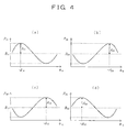
second transmission lines - Fig. 4 is an explanatory graph showing a procedure for detecting an error of each component using a REV method;
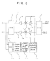
- Fig. 5 is a block diagram showing a structure of a variable power distributor according to
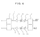
Embodiment 2 of the present invention; - Fig. 6 is a block diagram showing a structure of a variable power distributor used for a transmission system, according to
Embodiment 3 of the present invention; - Fig. 7 is an explanatory diagram showing a model of the variable power distributor shown in Fig. 6 which is made in view of an error included in each component;
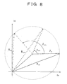
- Fig. 8 is an explanatory diagram showing a procedure for detecting an error of each component using an improved REV method;
- Fig. 9 is a block diagram showing a structure of a variable power distributor according to
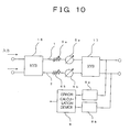
Embodiment 4 of the present invention; - Fig. 10 is a block diagram showing a structure of a variable power distributor used for a receiving system, according to Embodiment 5 of the present invention;
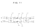
- Fig. 11 is an explanatory diagram showing a model of the variable power distributor shown in Fig. 10 which is made in view of an error included in each component;
- Fig. 12 is a block diagram showing a structure of a variable power distributor according to
Embodiment 6 of the present invention; and - Fig. 13 is a block diagram showing a structure of a variable power distributor of a conventional example.
- Fig. 1 is a block diagram showing a structure of a variable power distributor according to
Embodiment 1 of the present invention. As in the conventional example shown in Fig. 13, the variable power distributor shown in Fig. 1 includes a set of transmission lines which are afirst transmission line 1 and asecond transmission line 2, a 90-degree hybrid circuit 3 provided on an output side of the set of the transmission lines, and a 90-degree hybrid circuit 4 provided on an input side thereof. A first variable phase shifter 5a, a first variable resistance attenuator 6a, and a power amplifier 7a are provided on thefirst transmission line 1 between the 90-degree hybrid circuit 4 and the 90-degree hybrid circuit 3. A second variable phase shifter 5b, a second variable resistance attenuator 6b, and a power amplifier 7b are provided on thesecond transmission line 2 between the 90-degree hybrid circuit 4 and the 90-degree hybrid circuit 3. Note that the 90-degree hybrid circuit 4 in which one of input ends thereof is terminated is a two-way distributor (phases at two output ends are shifted to each other by 90 degrees). A normal two-way distributor may be provided instead of the 90-degree hybrid circuit 4. - The variable power distributor according to
Embodiment 1 further includes a first output signal monitoring mechanism 8a provided on a line branched from thefirst transmission line 1, a second output signal monitoring mechanism 8b provided on a line branched from thesecond transmission line 2, and anerror calculation device 9 serving as an error detection means for detecting an error ratio between the first andsecond transmission lines - Next, the operation of the variable power distributor according to
Embodiment 1 will be described. An input signal is divided into two to be distributed to two systems of thefirst transmission line 1 and thesecond transmission line 2 through the 90-degree hybrid circuit 4 the other input end of which is terminated. An amplitude and a phase of the input signal on each of the transmission lines are subjected to variable control through the variable phase shifter 5a (5b) and the variable resistance attenuator 6a (6b). Power of the signals is amplified by the power amplifier 7a (7b). The signals are distributed through the 90-degree hybrid circuit 3. - Output signals from the 90-
degree hybrid circuit 3 are inputted to the first output signal monitoring mechanism 8a and the second output signal monitoring mechanism 8b through the lines branched from thefirst transmission line 1 and thesecond transmission line 2. An amplitude and a phase of each of the output signals from the variable power distributor are monitored by the monitoring mechanisms. - A model of the variable power distributor shown in Fig. 1 which is made in view of an error included in each component is shown in Fig. 2. In Fig. 2, assume that the input signal is E0, the output signal on the
first transmission line 1 is E1, the output signal on thesecond transmission line 2 is E2, error amplitude values of the 90-degree hybrid circuit 3 with respect to the first andsecond transmission lines 1 and 2 (including an error between the systems, of the 90-degree hybrid circuit 3) are α2+ and α2-, respectively, error phase values of the 90-degree hybrid circuit 3 with respect to the first andsecond transmission lines 1 and 2 (including an error between the systems, of the 90-degree hybrid circuit 3) are δ2+ and δ2-, respectively, error amplitude values on an input side of the 90-degree hybrid circuit 3 with respect to the first andsecond transmission lines degree hybrid circuit 3 with respect to the first andsecond transmission lines 
- As shown in Fig. 3, the expression (1) expresses the output signals using a resultant electric field vector of two elements. Therefore, a rotating element electric field vector (REV) method described in a technical paper, "Element Amplitude and Phase Measuring Method of Phased Array Antenna -Rotating Element Electric Field Vector Method-" (Trans. IECE '82/5, Vol. J65-B, No. 5, pp. 555 to 560) can be applied to detect each component error.
- A procedure for detecting each component error using the REV method will be described below with reference to Fig. 4.
- (1) First, the phase of the first phase shifter 5a is rotated 360° and an output signal (power value P11) from the variable power distributor at the phase set value ϕR0 is recorded in the first output signal monitoring mechanism 8a (STEP 1). At this time, the second phase shifter 5b is not rotated. Then, the trajectory of the output signal P11 which is close to a cosine curve as shown in Fig. 4(a) is obtained.
- (2) Next, the phase of the first phase shifter 5a is rotated 360° and an output signal (power value P21) from the variable power distributor at the phase set value ϕR0 is recorded in the first output signal monitoring mechanism 8b (STEP 2). At this time, the second phase shifter 5b is not rotated. Then, the trajectory of the output signal P21 which is close to a cosine curve as shown in Fig. 4(b) is obtained.
- (3) Also, the phase of the second phase shifter 5b is rotated 360° and an output signal (power value P12) from the variable power distributor at the phase set value ϕL0 is recorded in the first output signal monitoring mechanism 8a (STEP 3). At this time, the first phase shifter 5a is not rotated. Then, the trajectory of the output signal P12 which is close to a cosine curve as shown in Fig. 4(c) is obtained.
- (4) Further, the phase of the second phase shifter 5b is rotated 360° and an output signal (power value P22) from the variable power distributor at the phase set value ϕL0 is recorded in the second output signal monitoring mechanism 8b (STEP 4). At this time, the first phase shifter 5a is not rotated. Then, the trajectory of the output signal P22 which is close to a cosine curve as shown in Fig. 4(d) is obtained.
- Note that the subscripts of the symbols used in this specification indicate the following relationships. For example, a first numeral "1" of a subscript "11" of the power value P11 corresponds to the output of the first output signal monitoring mechanism 8a and a second numeral "1" thereof corresponds to the case where the phase of the first variable phase shifter 5a is rotated. Similarly, a subscript "21" corresponds to the output of the second output signal monitoring mechanism 8b in the case where the phase of the first variable phase shifter 5a is rotated. A subscript "12" corresponds to the output of the first output signal monitoring mechanism 8a in the case where the phase of the second variable phase shifter 5b is rotated. A subscript "22" corresponds to the output of the second output signal monitoring mechanism 8b in the case where the phase of the second variable phase shifter 5b is rotated.
- Although the output signals obtained in the above-mentioned four STEPs are actually discrete values corresponding to the number of bits of the variable phase shifters 5a and 5b, an optimally fit cosine curve is obtained using a least squares approximation or the like (Fig. 4). The monitoring outputs are sent to the
error calculation device 9. - The
error calculation device 9 calculates a relative amplitude k and a relative phase X from values read from the cosine curve shown in Fig. 4 based on the following procedure. Here, an example in the case where the output signal data from thefirst transmission line 1 is used (Fig. 4(a) and Fig. 4(c)) will be described. - In Fig. 4(a), assume that a ratio between a minimal value and a maximal value of power is r11 2, a phase set value of the first phase shifter 5a at the time of a maximal value A11 is -Δ11, and an intermediate value between the minimal value and the maximal value of power is B11. Then, r11 can be expressed by the expression (2).

- Here, fundamentally, A11 ≤ B11. Note that A11 > B11 may be held by an error caused by least squares approximation, a measurement system error, or the like. In this case, approximate calculation is performed under a condition of A11 = B11. A sign of r11 becomes positive in the case where a variation in phase of the output signal obtained by the first output signal monitoring mechanism 8a is equal to or smaller than 180° when the phase of the variable phase shifter 5a is rotated. The sign of r11 becomes negative in the case where the variation is larger than 180°. Therefore, a solution expressed by the expression (3) is obtained from the expression (2).

where
Here, E10 and ϕ10 indicate an amplitude and a phase of an initial resultant electric field vector observed in the output signal on thefirst transmission line 1, respectively (see Fig. 3). - Similarly, in a cosine curve of the output signal obtained when the phase of the variable phase shifter 5b is rotated (Fig. 4(c)), assume that a ratio between a minimal value and a maximal value of power is r12 and a phase set value at the time of the maximal value is -Δ12. Then, when a relative amplitude k12 and a relative phase X12 are to be obtained using those values with reference to the above-mentioned procedure, the relative amplitude and the relative phase are expressed by the expression (5). Note that the sign of r12 becomes reverse to that of r11.

- The output signal on the
second transmission line 2 is processed in the same procedure as that described above to obtain relative amplitudes k (k21 and k22) and a relative phases X (X21 and X22) which are expressed by the expression (6).
- Here, E20 and ϕ20 indicate an amplitude and a phase of an initial resultant electric field vector observed in the output signal on the
second transmission line 2, respectively. - As a result, the phases of the variable phase shifters 5a and 5b are rotated, the parameters related to errors (amplitudes and phases) of the variable power distributor are obtained from the expressions (3), (5), and (6) based on the principal of the REV method. An amplitude error ratio of the 90-
degree hybrid circuit 3 of the variable power distributor between the first andsecond transmission lines degree hybrid circuit 3 between the first andsecond transmission lines 

- Such calculation processing is executed for error detection by the
calculation processing device 9. - As is apparent from the above description, according to
Embodiment 1, the output signals on the first andsecond transmission lines error calculation device 9 and subjected to calculation processing using the REV method. Therefore, it is possible to detect an error (relative value between the first transmission line and the second transmission line) of each of the components of the variable power distributor. According to the error detection, the error in each of the components can be estimated after the variable power distributor is built. Therefore, it is possible to significantly shorten an estimation measurement time and reduce a cost. - Fig. 5 is a block diagram showing a structure of a variable power distributor according to
Embodiment 2 of the present invention. In addition to the same structure as that inEmbodiment 1 as shown in Fig. 1, the variable power distributor according toEmbodiment 2 as shown in Fig. 5 further includes a correctionvalue calculation device 10 for calculating amplitude correction values and phase correction values for the variable resistance attenuators 6a and 6b and the variable phase shifters 5a and 5b based on outputs of theerror calculation device 9 and an amplitude and phase control device 11 for controlling the amplitude correction values and the phase correction values for the variable resistance attenuators 6a and 6b and the variable phase shifters 5a and 5b based on an output of the correctionvalue calculation device 10. - Next, the operation of the variable power distributor according to
Embodiment 2 will be described. According toEmbodiment 1 described above, it is possible to detect the error (relative value between the first transmission line and the second transmission line) of each of the components of the variable power distributor. InEmbodiment 2, amplitude set values and phase set values of the variable power distributor are corrected based on the errors to control amplitudes and phases. Error values obtained by theerror calculation device 9 are sent to the correctionvalue calculation device 10. In the correctionvalue calculation device 10, the expressions (7) and (8) expressing the errors are substituted by the following expressions.

- When the correction values to be obtained are expressed as ratios between the
first transmission line 1 and thesecond transmission line 2, the following expressions are obtained.

- When the expression (1) is modified using the expressions (9) to (12), a ratio therebetween is expressed by the following expression.

- Here, when the left side of the above-mentioned expression is subjected to polar display and then the expression is rearranged, the following expression is obtained.

- Therefore, an amplitude ratio A and a phase difference ψ as the correction values of the variable power distributor between the two transmission lines are expressed by the following expressions.


where
- The amplitude ratio A is obtained by the substitution of the expression (16) into the expression (15). Similarly, the phase difference ψ is obtained by the substitution of the expression (17) into the expression (16).
- As is apparent from the above description, according to
Embodiment 2, the values for correcting the amplitude and phase set values in which the errors in the variable power distributor are taken into consideration can be derived based on the error (relative value between the first transmission line and the second transmission line) of each of the components of the variable power distributor. - The correction values are sent to the amplitude and phase correction value control device 11. Therefore, the control can be made so as to correct the set values for the variable resistance attenuators 6a and 6b and the variable phase shifters 5a and 5b.
- As shown in Fig. 5, derivation and control systems of the amplitude and phase correction values are wired so as to give feedback to the system of the variable power distributor, thereby making it possible to make automatic feedback control to the operation of the systems.
- Fig. 6 is a block diagram showing a structure of a variable power distributor used in a transmission system according to
Embodiment 3 of the present invention. As in the conventional example shown in Fig. 13, the variable power distributor used in a transmission system shown in Fig. 6 includes a set of transmission lines which are afirst transmission line 1 and asecond transmission line 2, a 90-degree hybrid circuit 3 provided on an output side of the set of the transmission lines, and a two-way distributor 13 provided on an input side thereof. A first variable phase shifter 5a, a first variable resistance attenuator 6a, and a power amplifier 7a are provided on thefirst transmission line 1 between the two-way distributor 13 and the 90-degree hybrid circuit 3. A second variable phase shifter 5b, a second variable resistance attenuator 6b, and a power amplifier 7b are provided on thesecond transmission line 2 between the 90-degree hybrid circuit 4 and the 90-degree hybrid circuit 3. Note that the 90-degree hybrid circuit in which one of input ends thereof is terminated is a two-way distributing circuit (phases at two output ends are shifted to each other by 90 degrees), and may be provided instead of the two-way distributor 13. - The variable power distributor according to
Embodiment 3 further includes a first output signal monitoring mechanism 8a provided on a line branched from thefirst transmission line 1, a second output signal monitoring mechanism 8b provided on a line branched from thesecond transmission line 2, and anerror calculation device 9 serving as an error detection means for detecting an error ratio between the first andsecond transmission lines - Next, the operation of the variable power distributor according to
Embodiment 3 will be described. An input signal is branched to two systems of thefirst transmission line 1 and thesecond transmission line 2 through the two-way distributor 13. An amplitude and a phase of the input signal on each of the transmission lines are subjected to variable control through the variable phase shifter 5a (5b) and the variable resistance attenuator 6a (6b). Power of the signals is amplified by the power amplifier 7a (7b). The signals are distributed through the 90-degree hybrid circuit 3. - Output signals from the 90-
degree hybrid circuit 3 are inputted to the first output signal monitoring mechanism 8a and the second output signal monitoring mechanism 8b through the lines branched from thefirst transmission line 1 and thesecond transmission line 2. An amplitude and a phase of each of the output signals from the variable power distributor are monitored by the monitoring mechanisms. - Here, a model of the variable power distributor shown in Fig. 6 which is made in view of an error included in each component is shown in Fig. 7. In Fig. 7, assume that the input signal is E0, the output signal on the
first transmission line 1 is E1, the output signal on thesecond transmission line 2 is E2, an error electric field value on an output side (output-terminal-E1-and-E2 side) relative to the 90-degree hybrid circuit 3 with respect to the first andsecond transmission lines degree hybrid circuit 3 with respect to the first andsecond transmission lines way distributor 13 side) relative to the 90-degree hybrid circuit 3 with respect to the first andsecond transmission lines - Next, an improved rotating element electric field vector (REV) method described in a technical paper, "Method of Measuring Array Element Electric Field and Phase Shifter Error Using Amplitude and Phase of Resultant Electric Field of Phased Array Antenna -Improved Rotating Element Electric Field Vector Method-" (Trans. IEICE '02/9, Vol. J85-B, No. 9, pp. 1558 to 1565) is applied to detect each component error.
- A procedure for detecting each component error using the improved REV method will be described below.
- (1) First, the phase of the first phase shifter 5a is rotated 360° and an output signal (power value E1Rm) from the variable power distributor at the phase set value ΔRm is recorded in the first output signal monitoring mechanism 8a. At this time, the second phase shifter 5b is not rotated. Fig. 8 is a vector diagram showing the transition of the power value E1Rm at this time.
- (2) Next, the phase of the first phase shifter 5a is rotated 360° and an output signal (power value E2Rm) from the variable power distributor at the phase set value ΔRm is recorded in the second output signal monitoring mechanism 8b. At this time, the second phase shifter 5b is not rotated.
- (3) Also, the phase of the second phase shifter 5b is rotated 360° and an output signal (power value E1Lm) from the variable power distributor at the phase set value ΔLm is recorded in the first output signal monitoring mechanism 8a. At this time, the first phase shifter 5a is not rotated.
- (4) Further, the phase of the first phase shifter 5b is rotated 360° and an output signal (power value E2Lm) from the variable power distributor at the phase set value ΔLm is recorded in the second output signal monitoring mechanism 8b. At this time, the first phase shifter 5a is not rotated.
- An electric field value of each system in the case where the phase of the variable phase shifter is rotated is expressed by the expression (18) based on the output signals obtained in the above-mentioned four steps. Note that reference symbol M denotes the number of phase shifters to be set.

- In order words, the electric field value of each system in the case where the phase of the variable phase shifter is rotated, which is expressed by the expression (18) is changed according to the phase set value. Therefore, four electric field values J1Rm, J2Rm, J1Lm, and J2Lm are obtained by the above-mentioned steps.
- Here, J1Rm indicates the electric field value on the
first transmission line 1 in the case where the phase of the first phase shifter 5a is rotated 360° and an output signal (electric field value E1Rm) from the variable power distributor at a phase set value ΔRm is recorded in the first output signal monitoring mechanism 8a. - Also, J2Rm indicates the electric field value on the
first transmission line 1 in the case where the phase of the first phase shifter 5a is rotated 360° and an output signal (electric field value E2Rm) from the variable power distributor at a phase set value ΔRm is recorded in the second output signal monitoring mechanism 8b. - Also, J1Lm indicates the electric field value on the
second transmission line 2 in the case where the phase of the second phase shifter 5b is rotated 360° and an output signal (electric field value E1Lm) from the variable power distributor at a phase set value ΔRm is recorded in the first output signal monitoring mechanism 8a. - Further, J2Lm indicates the electric field value on the
second transmission line 2 in the case where the phase of the second phase shifter 5b is rotated 360° and an output signal (electric field value E2Lm) from the variable power distributor at a phase set value ΔRm is recorded in the second output signal monitoring mechanism 8b. - When the electric field value J2Lm is used as a reference, the error
electric field value 10 on the output side (output-terminal-J1-and-J2 side) relative to the 90-degree hybrid circuit 3 with respect to the first andsecond transmission lines degree hybrid circuit 3 with respect to the first andsecond transmission lines way distributor 13 side) relative to the 90-degree hybrid circuit 3 with respect to the first andsecond transmission lines 


- Such calculation processing is executed for error detection by the
error calculation device 9. - As is apparent from the above description, according to
Embodiment 3, the output signals on the first andsecond transmission lines error calculation device 9 and subjected to calculation processing using the improved REV method. Therefore, it is possible to detect an error (relative value between the first transmission line and the second transmission line) of each of the components of the variable power distributor. According to the error detection, the error in each of the components can be estimated after the variable power distributor is built. Therefore, it is possible to significantly shorten an estimation measurement time and reduce a cost. - Fig. 9 is a block diagram showing a structure of a variable power distributor according to
Embodiment 4 of the present invention. In addition to the same structure as that inEmbodiment 4 as shown in Fig. 9, the variable power distributor according toEmbodiment 3 as shown in Fig. 6 further includes a correctionvalue calculation device 10 for calculating amplitude correction values and phase correction values for the variable resistance attenuators 6a and 6b and the variable phase shifters 5a and 5b based on outputs of theerror calculation device 9 and an amplitude and phase control device 11 for controlling the amplitude correction values and the phase correction values for the variable resistance attenuators 6a and 6b and the variable phase shifters 5a and 5b based on an output of the correctionvalue calculation device 10. - Next, the operation of the variable power distributor according to
Embodiment 4 will be described. According toEmbodiment 3 described above, the error (relative value between the first transmission line and the second transmission line) of each of the components of the variable power distributor is detected. InEmbodiment 4, amplitude set values and phase set values of the variable power distributor are corrected based on the errors to control amplitudes and phases. The values for correcting the amplitude and phase set values in which the errors in the variable power distributor are taken into calculation are calculated by the correctionvalue calculation device 10 based on the error (relative value between the first transmission line and the second transmission line) of each of the components of the variable power distributor. The correction values are sent to the amplitude and phase correction value control device 11. Therefore, the control can be made so as to correct the set values for the variable resistance attenuators 6a and 6b and the variable phase shifters 5a and 5b. Note that the correctionvalue calculation device 10 calculates the correction values so as to cancel the errors obtained by theerror calculation device 9. - As shown in Fig. 9, derivation and control systems of the amplitude and phase correction values are wired so as to give feedback to the system of the variable power distributor, so that automatic feedback control can be made to the operation of the systems.
- Fig. 10 is a block diagram showing a structure of a variable power distributor used in a reception system according to
Embodiment 5 of the present invention. As in the conventional example shown in Fig. 13, the variable power distributor shown in Fig. 10 according toEmbodiment 5 includes a set of transmission lines which are afirst transmission line 1 and asecond transmission line 2, a 90-degree hybrid circuit 17 provided on an output side of the set of the transmission lines, and a 90-degree hybrid circuit 16 provided on an input side thereof. A first variable phase shifter 5a and a first variable resistance attenuator 6a are provided on thefirst transmission line 1 between the 90-degree hybrid circuit 16 and the 90-degree hybrid circuit 17. A second variable phase shifter 5b and a second variable resistance attenuator 6b are provided on thesecond transmission line 2 between the 90-degree hybrid circuit 16 and the 90-degree hybrid circuit 17. - The variable power distributor according to
Embodiment 5 further includes a first output signal monitoring mechanism 8a provided on a line branched from thefirst transmission line 1, a second output signal monitoring mechanism 8b provided on a line branched from thesecond transmission line 2, and anerror calculation device 9 serving as an error detection means for detecting an error ratio between the first andsecond transmission lines - Next, the operation of the variable power distributor according to
Embodiment 5 will be described. An input signal is branched to two systems of thefirst transmission line 1 and thesecond transmission line 2 through the 90-degree hybrid circuit 16. An amplitude and a phase of the input signal on each of the transmission lines are subjected to variable control through the variable phase shifter 5a (5b) and the variable resistance attenuator 6a (6b), and the signal is distributed through the 90-degree hybrid circuit 17. - Output signals from the 90-
degree hybrid circuit 17 are inputted to the first output signal monitoring mechanism 8a and the second output signal monitoring mechanism 8b through the lines branched from thefirst transmission line 1 and thesecond transmission line 2. An amplitude and a phase of each of the output signals from the variable power distributor are monitored by the monitoring mechanisms. - Here, a model of the variable power distributor shown in Fig. 10 which is made in view of an error included in each component is shown in Fig. 11. In Fig. 11, assume that an input signal on the first transmission line 1 is E01, an input signal on the second transmission line 2 is E02, the output signal on the first transmission line 1 is E1, the output signal on the second transmission line 2 is E2, an error electric field value on an input side (input terminal E01 and E02 side) relative to the 90-degree hybrid circuit 16 with respect to the first and second transmission lines 1 and 2 is δ1, an error electric field value of the 90-degree hybrid circuit 16 with respect to the first and second transmission lines 1 and 2 is δh1, an error electric field value on the first transmission line 1 between the 90-degree hybrid circuit 16 and the 90-degree hybrid circuit 17 with respect to the first and second transmission lines 1 and 2 is CR, and an error electric field value on the second transmission line 2 therebetween is CL. In addition, assume that an error electric field value of the 90-degree hybrid circuit 16 with respect to the first and second transmission lines 1 and 2 is δh2 and an error electric field value on an output side (output-terminal-E1-and-E2 side) relative to the 90-degree hybrid circuit 17 with respect to the first and second transmission lines 1 and 2 is δ3.
- Next, a procedure for detecting each component error using the improved REV method will be described below.
- (1) First, when input from the input terminal E01, the phase of the first phase shifter 5a is rotated 360° and an output signal (power value E1Rm-01) from the variable power distributor at the phase set value ΔRm is recorded in the first output signal monitoring mechanism 8a. At this time, the second phase shifter 5b is not rotated.
- (2) Next, when input from the input terminal E01, the phase of the first phase shifter 5a is rotated 360° and an output signal (power value E2Rm-01) from the variable power distributor at the phase set value ΔRm is recorded in the first output signal monitoring mechanism 8b. At this time, the second phase shifter 5b is not rotated.
- (3) Also, when input from the input terminal E01, the phase of the second phase shifter 5b is rotated 360° and an output signal (power value E1Lm-01) from the variable power distributor at the phase set value ΔLm is recorded in the first output signal monitoring mechanism 8a. At this time, the first phase shifter 5a is not rotated.
- (4) Further, when input from the input terminal E01, the phase of the first phase shifter 5b is rotated 360° and an output signal (power value E2Lm-01) from the variable power distributor at the phase set value ΔLm is recorded in the second output signal monitoring mechanism 8b. At this time, the first phase shifter 5a is not rotated.
- (5) Then, when input from the input terminal E02, the phase of the first phase shifter 5a is rotated 360° and an output signal (power value E1Rm-02) from the variable power distributor at the phase set value ΔRm is recorded in the first output signal monitoring mechanism 8a. At this time, the second phase shifter 5b is not rotated.
- (6) Next, when input from the input terminal E02, the phase of the first phase shifter 5a is rotated 360° and an output signal (power value E2Rm-02) from the variable power distributor at the phase set value ΔRm is recorded in the second output signal monitoring mechanism 8b. At this time, the second phase shifter 5b is not rotated.
- (7) Also, when input from the input terminal E02, the phase of the first phase shifter 5b is rotated 360° and an output signal (power value E1Lm-02) from the variable power distributor at the phase set value ΔLm is recorded in the first output signal monitoring mechanism 8a. At this time, the first phase shifter 5a is not rotated.
- (8) Further, when input from the input terminal E02, the phase of the first phase shifter 5b is rotated 360° and an output signal (power value E2Lm-02) from the variable power distributor at the phase set value ΔLm is recorded in the second output signal monitoring mechanism 8b. At this time, the first phase shifter 5a is not rotated.
- An electric field value of each system in the case where the phase of the variable phase shifter is rotated is expressed by the expression (18) based on the output signals obtained in the above-mentioned eight steps.
- In order words, the electric field value of each system in the case where the phase of the variable phase shifter is rotated, which is expressed by the expression (18) is changed according to the phase set value. Therefore, eight electric field values C'1Rm, C'2Rm, C'1Lm, C'2Lm, C"1Rm, C"2Rm, C"1Lm, and C"2Lm are obtained by the above-mentioned steps.
- Here, C'1Rm indicates the electric field value on the
first transmission line 1 in the case where the phase of the first phase shifter 5a is rotated 360° and an output signal (electric field value E1Rm-01) from the variable power distributor at a phase set value ΔRm is recorded in the first output signal monitoring mechanism 8a when an input signal is inputted from the input terminal E01. - Also, C'2Rm indicates the electric field value on the
first transmission line 1 in the case where the phase of the first phase shifter 5a is rotated 360° and an output signal (electric field value E2Rm-01) from the variable power distributor at a phase set value ΔRm is recorded in the second output signal monitoring mechanism 8b when an input signal is inputted from the input terminal E01. - Also, C'1Lm indicates the electric field value on the
second transmission line 2 in the case where the phase of the second phase shifter 5b is rotated 360° and an output signal (electric field value E1Lm-01) from the variable power distributor at a phase set value ΔLm is recorded in the first output signal monitoring mechanism 8a when an input signal is inputted from the input terminal E01. - Also, C'2Lm indicates the electric field value on the
second transmission line 2 in the case where the phase of the second phase shifter 5b is rotated 360° and an output signal (electric field value E2Lm-01) from the variable power distributor at a phase set value ΔLm is recorded in the second output signal monitoring mechanism 8b when an input signal is inputted from the input terminal E01. - Also, C"1Rm indicates the electric field value on the
first transmission line 1 in the case where the phase of the first phase shifter 5a is rotated 360° and an output signal (electric field value E1Rm-02) from the variable power distributor at a phase set value ΔRm is recorded in the first output signal monitoring mechanism 8a when an input signal is inputted from the input terminal E02. - Also, C"2Rm indicates the electric field value on the
first transmission line 1 in the case where the phase of the first phase shifter 5a is rotated 360° and an output signal (electric field value E2Rm-02) from the variable power distributor at a phase set value ΔRm is recorded in the second output signal monitoring mechanism 8b when an input signal is inputted from the input terminal E02. - Also, C"1Lm indicates the electric field value on the
second transmission line 2 in the case where the phase of the second phase shifter 5b is rotated 360° and an output signal (electric field value E1Lm-02) from the variable power distributor at a phase set value ΔLm is recorded in the first output signal monitoring mechanism 8a when an input signal is inputted from the input terminal E02. - Further, C"2Lm indicates the electric field value on the
second transmission line 2 in the case where the phase of the second phase shifter 5b is rotated 360° and an output signal (electric field value E2Lm-02) from the variable power distributor at a phase set value ΔLm is recorded in the second output signal monitoring mechanism 8b when an input signal is inputted from the input terminal E02. - Here, the error electric field value δ1 on the input side (input terminal E01 and E02 side) relative to the 90-degree hybrid circuit 16 with respect to the first and
second transmission lines second transmission lines first transmission line 1 between the 90-degree hybrid circuit 16 and the 90-degree hybrid circuit 17 with respect to the first andsecond transmission lines second transmission line 2 therebetween, the error electric field value δh2 of the 90-degree hybrid circuit 16 with respect to the first andsecond transmission lines degree hybrid circuit 17 with respect to the first andsecond transmission lines 


- Such calculation processing is executed for error detection by the
calculation processing device 9. - As is apparent from the above description, according to
Embodiment 5, the output signals on the first andsecond transmission lines error calculation device 9 and subjected to calculation processing using the improved REV method. Therefore, it is possible to detect an error (relative value between the first transmission line and the second transmission line) in each of the components of the variable power distributor. According to the error detection, the error in each of the components can be estimated after the variable power distributor is built. Therefore, it is possible to significantly shorten an estimation measurement time and reduce a cost. - Fig. 12 is a block diagram showing a structure of a variable power distributor according to
Embodiment 6 of the present invention. As inEmbodiment 4 shown in Fig. 9, in addition to the same structure as that inEmbodiment 5 as shown in Fig. 10, the variable power distributor according toEmbodiment 6 as shown in Fig. 12 further includes the correctionvalue calculation device 10 for calculating amplitude correction values and phase correction values for the variable resistance attenuators 6a and 6b and the variable phase shifters 5a and 5b based on outputs of theerror calculation device 9 and the amplitude and phase control device 11 for controlling the amplitude correction values and the phase correction values for the variable resistance attenuators 6a and 6b and the variable phase shifters 5a and 5b based on an output of the correctionvalue calculation device 10. - That is, the values for correcting the amplitude and phase set values in which the errors in the variable power distributor are taken into calculation are calculated by the correction
value calculation device 10 based on the detected error (relative value between the first transmission line and the second transmission line) in each of the components of the variable power distributor. The correction values are sent to the amplitude and phase control device 11. Therefore, the control can be made so as to correct the set values for the variable resistance attenuators 6a and 6b and the variable phase shifters 5a and 5b. Note that the correction value calculation device calculates the correction values so as to cancel the errors obtained by theerror calculation device 9. - As in
Embodiment 4, the derivation and control systems of the amplitude and phase correction values are wired so as to give feedback to the system of the variable power distributor, thereby making it possible to perform automatic feedback control on the operation of the systems. - As described above, according to the present invention, it is possible to obtain a variable power distributor in which an amplitude ratio and a phase difference as errors between transmission lines of two systems can be calculated after the variable power distributor is built and the amplitude and phase set values are corrected based on the errors, an error detection method thereof, and a set value correction method.
Claims (17)
- A variable power distributor, which includes:a set of transmission lines which are first and second transmission lines;a two-way distributor provided on an input side of the set of the transmission lines;a 90-degree hybrid circuit provided on an output side of the set of the transmission lines; anda variable phase shifter, a variable resistance attenuator, and a power amplifier which are provided on each of the set of transmission lines between the two-way distributor and the 90-degree hybrid circuit to control an amplitude and a phase of an input signal and amplify power of the input signal, the variable power distributor being characterized by comprising:a monitoring mechanism for monitoring output signals from the 90-degree hybrid circuit; anderror detection means for detecting an error present in each component between the first and second transmission lines based on a monitoring output from the monitoring mechanism.
- The variable power distributor according to claim 1, characterized in that
the error detection means obtains, from the monitoring mechanism, output signals on the first and second transmission lines when a phase of the variable phase shifter provided on the first transmission line is rotated and output signals on the first and second transmission lines when a phase of the variable phase shifter provided on the second transmission line is rotated, and detects the error present in each component between the first and second transmission lines using a rotating element electric field vector method. - The variable power distributor according to claim 2, characterized by further comprising
control means for controlling the amplitude and the phase by correcting set values for the variable phase shifters and the variable resistance attenuators based on a detection result obtained by the error detection means. - The variable power distributor according to claim 3, characterized in that
the control means calculates an amplitude ratio and a phase difference between the first and second transmission lines based on the detection result obtained by the error detection means to correct the set values for the variable phase shifters and the variable resistance attenuators. - An error detection method for a variable power distributor that includes: a set of transmission lines which are first and second transmission lines; a two-way distributor provided on an input side of the set of the transmission lines; a 90-degree hybrid circuit provided on an output side of the set of the transmission lines; and a variable phase shifter, a variable resistance attenuator, and a power amplifier which are provided on each of the set of transmission lines between the two-way distributor and the 90-degree hybrid circuit to control an amplitude and a phase of an input signal and amplify power of the input signal and detects an error present in each component between the first and second transmission lines, the error detection method being characterized by comprising:detecting output signals from the first and second transmission lines when a phase of the variable phase shifter provided on the first transmission line is rotated;detecting output signals based on the first and second transmission lines when a phase of the variable phase shifter provided on the second transmission line is rotated; anddetecting the error present in each component based on the output signals using a rotating element electric field vector method.
- A set value correction method for the variable power distributor, characterized by comprising:obtaining an amplitude ratio and a phase difference between the first and second transmission lines based on a detection result of the error detected by the error detection method for the variable power distributor according to claim 5; and correcting set values for the variable phase shifters and the variable resistance attenuators.
- The variable power distributor according to claim 1, characterized in that
the error detection means obtains, from the monitoring mechanism, output signals on the first and second transmission lines when a phase of the variable phase shifter provided on the first transmission line is rotated and output signals on the first and second transmission lines when a phase of the variable phase shifter provided on the second transmission line is rotated, and detects the error present in each component between the first and second transmission lines using an improved rotating element electric field vector method. - The variable power distributor according to claim 7, characterized by further comprising
control means for controlling the amplitude and the phase by correcting set values for the variable phase shifters and the variable resistance attenuators based on a detection result obtained by the error detection means. - The variable power distributor according to claim 8, characterized in that
the control means calculates an amplitude ratio and a phase difference between the first and second transmission lines based on the detection result obtained by the error detection means to correct the set values for the variable phase shifters and the variable resistance attenuators. - An error detection method for a variable power distributor that includes: a set of transmission lines which are first and second transmission lines; a two-way distributing circuit provided on an input side of the set of the transmission lines; a 90-degree hybrid circuit provided on an output side of the set of the transmission lines; and a variable phase shifter, a variable resistance attenuator, and a power amplifier which are provided on each of the set of transmission lines between the two-way distributor and the 90-degree hybrid circuit to control an amplitude and a phase of an input signal and amplify power of the input signal and detects an error present in each component between the first and second transmission lines, the error detection method being characterized by comprising:detecting output signals from the first and second transmission lines when a phase of the variable phase shifter provided on the first transmission line is rotated;detecting output signals from the first and second transmission lines when a phase of the variable phase shifter provided on the second transmission line is rotated; anddetecting the error present in each component from the output signals using a rotating element electric field vector method.
- A set value correction method for the variable power distributor, characterized by comprising:obtaining an amplitude ratio and a phase difference between the first and second transmission lines based on a detection result of the error detected by the error detection method for the variable power distributor according to claim 10; andcorrecting set values for the variable phase shifters and the variable resistance attenuators.
- A variable power distributor including:a set of transmission lines which are first and second transmission lines;a 90-degree hybrid circuit provided on each of input and output sides of the set of the transmission lines; anda variable phase shifter and a variable resistance attenuator which are provided on each of the set of transmission lines between the 90-degree hybrid circuit provided on the input side and the 90-degree hybrid circuit provided on the output side to control an amplitude and a phase of an input signal, the variable power distributor being characterized by comprising:a monitoring mechanism for monitoring output signals from the 90-degree hybrid circuit; anderror detection means for detecting an error present in each component between the first and second transmission lines based on a monitoring output from the monitoring mechanism.
- The variable power distributor according to claim 12, characterized in that
the error detection means obtains, from the monitoring mechanism, output signals on the first and second transmission lines when a phase of the variable phase shifter provided on the first transmission line is rotated and output signals on the first and second transmission lines when a phase of the variable phase shifter provided on the second transmission line is rotated and
detects the error present in each component between the first and second transmission lines using an improved rotating element electric field vector method. - The variable power distributor according to claim 13, characterized by further comprising
control means for controlling the amplitude and the phase by correcting set values for the variable phase shifters and the variable resistance attenuators based on a detection result obtained by the error detection means. - The variable power distributor according to claim 14, characterized in that
the control means calculates an amplitude ratio and a phase difference between the first and second transmission lines based on the detection result obtained by the error detection means to correct the set values for the variable phase shifters and the variable resistance attenuators. - An error detection method for a variable power distributor that includes: a set of transmission lines which are first and second transmission lines; a 90-degree hybrid circuit provided on each of input and output sides of the set of the transmission lines; and a variable phase shifter and a variable resistance attenuator which are provided on each of the set of transmission lines between the 90-degree hybrid circuit provided on the input side and the 90-degree hybrid circuit provided on the output side to control an amplitude and a phase of an input signal and detects an error present in each component between the first and second transmission lines, the error detection method being characterized by comprising:detecting output signals from the first and second transmission lines when a phase of the variable phase shifter provided on the first transmission line is rotated;detecting output signals from the first and second transmission lines when a phase of the variable phase shifter provided on the second transmission line is rotated; anddetecting the error present in each component based on the output signals using an improved rotating element electric field vector method.
- A set value correction method for a variable power distributor, characterized by comprising:obtaining an amplitude ratio and a phase difference between the first and second transmission lines based on a detection result of an error detected by the error detection method for a variable power distributor according to claim 16; andcorrecting set values for the variable phase shifters and the variable resistance attenuators.
Applications Claiming Priority (2)
| Application Number | Priority Date | Filing Date | Title |
|---|---|---|---|
| PCT/JP2003/012543 WO2005034350A1 (en) | 2003-09-30 | 2003-09-30 | Variable power distributor, its error detecting method and set value correcting method |
| PCT/JP2004/004270 WO2005034281A1 (en) | 2003-09-30 | 2004-03-26 | Variable power distributor, error detection method thereof, and set value correction method |
Publications (2)
| Publication Number | Publication Date |
|---|---|
| EP1670092A1 true EP1670092A1 (en) | 2006-06-14 |
| EP1670092A4 EP1670092A4 (en) | 2007-05-16 |
Family
ID=34401440
Family Applications (1)
| Application Number | Title | Priority Date | Filing Date |
|---|---|---|---|
| EP04723747A Withdrawn EP1670092A4 (en) | 2003-09-30 | 2004-03-26 | VARIABLE POWER DISTRIBUTOR AND ITS ERROR DETECTION METHOD, AND VALUE CORRECTION METHOD |
Country Status (4)
| Country | Link |
|---|---|
| US (1) | US7587652B2 (en) |
| EP (1) | EP1670092A4 (en) |
| JP (1) | JP4166787B2 (en) |
| WO (2) | WO2005034350A1 (en) |
Cited By (2)
| Publication number | Priority date | Publication date | Assignee | Title |
|---|---|---|---|---|
| EP2985838A1 (en) * | 2014-08-15 | 2016-02-17 | Honeywell International Inc. | Systems and methods for high power microwave combining and switching |
| CN108702140A (en) * | 2016-02-17 | 2018-10-23 | 三菱电机株式会社 | Multiphase filter and filter circuit |
Families Citing this family (7)
| Publication number | Priority date | Publication date | Assignee | Title |
|---|---|---|---|---|
| JP4782090B2 (en) * | 2007-09-27 | 2011-09-28 | 日本電信電話株式会社 | Wireless transmitter and wireless transmission method |
| US8059761B2 (en) * | 2008-07-10 | 2011-11-15 | Xilinx, Inc. | Detecting in-phase and quadrature-phase amplitudes of MIMO communications |
| US8213880B2 (en) * | 2008-10-15 | 2012-07-03 | Rockstar Bidco, LP | Minimum feedback radio architecture with digitally configurable adaptive linearization |
| US8843088B2 (en) | 2008-10-15 | 2014-09-23 | Apple Inc. | Minimum feedback radio architecture with digitally configurable adaptive linearization |
| JP5828069B2 (en) | 2011-07-27 | 2015-12-02 | パナソニックIpマネジメント株式会社 | Power distribution circuit |
| EP4205238A1 (en) * | 2020-10-07 | 2023-07-05 | Huawei Technologies Co., Ltd. | Antenna device with collaborative radiators for parameter control |
| DE102023211011A1 (en) | 2023-11-07 | 2025-05-08 | Robert Bosch Gesellschaft mit beschränkter Haftung | Phase shifter device and method for shifting a phase of a signal |
Family Cites Families (20)
| Publication number | Priority date | Publication date | Assignee | Title |
|---|---|---|---|---|
| JPS59153333A (en) * | 1983-02-21 | 1984-09-01 | Nippon Telegr & Teleph Corp <Ntt> | Phase and frequency variable oscillator |
| JPH0630404B2 (en) * | 1986-05-14 | 1994-04-20 | 三菱電機株式会社 | Antenna measuring device |
| IT1223301B (en) * | 1987-09-11 | 1990-09-19 | Eniricerche Spa | IMMUNOLOGICALLY ACTIVE SEQUENTIAL POLYPEPTIDES |
| JPH01117464A (en) | 1987-10-30 | 1989-05-10 | Iiguretsuku Syst:Kk | Communication controller |
| JPH0793546B2 (en) * | 1988-09-26 | 1995-10-09 | 日本電信電話株式会社 | Amplifier |
| JPH03165603A (en) * | 1989-11-24 | 1991-07-17 | Nec Corp | Amplitude phase control circuit for high frequency signal |
| JPH0595201A (en) * | 1991-07-03 | 1993-04-16 | Nippon Telegr & Teleph Corp <Ntt> | Complex conjugate signal generator |
| JPH0537263A (en) * | 1991-07-30 | 1993-02-12 | Fujitsu Ltd | Constant amplitude wave synthesis amplifier |
| JP3367735B2 (en) * | 1994-02-16 | 2003-01-20 | 三菱電機株式会社 | RF device for measuring distortion characteristics and method for measuring distortion characteristics |
| JP2522201B2 (en) * | 1994-06-24 | 1996-08-07 | 日本電気株式会社 | Phase control circuit for power synthesis |
| JP2760304B2 (en) * | 1995-02-07 | 1998-05-28 | 日本電気株式会社 | Power amplifier |
| US6016304A (en) * | 1996-08-07 | 2000-01-18 | Raytheon Company | RF phase and/or amplitude control device |
| JPH1117464A (en) * | 1997-06-26 | 1999-01-22 | Hitachi Denshi Ltd | Phase shifter |
| JPH1168443A (en) * | 1997-08-11 | 1999-03-09 | Mitsubishi Electric Corp | Digital beamforming antenna device |
| US5940448A (en) * | 1997-09-03 | 1999-08-17 | National Semiconductor Corporation | Universal serial bus receiver having input signal skew compensation |
| US6006111A (en) * | 1997-10-08 | 1999-12-21 | Nortel Networks Corporation | Self-balancing matrix amplifier |
| JP3096734B2 (en) * | 1998-09-04 | 2000-10-10 | 郵政省通信総合研究所長 | Transmit array antenna calibration method |
| JP2001007656A (en) * | 1999-06-18 | 2001-01-12 | Japan Radio Co Ltd | Distortion compensation method and circuit |
| EP1113637B1 (en) * | 1999-12-28 | 2006-04-05 | NTT DoCoMo, Inc. | Circuit for the compression of the dynamic range of a signal |
| US6980831B2 (en) * | 2000-12-08 | 2005-12-27 | Matsushita Electric Industrial Co., Ltd. | Radio communication base state system including optical advanced base station |
-
2003
- 2003-09-30 WO PCT/JP2003/012543 patent/WO2005034350A1/en not_active Ceased
-
2004
- 2004-03-26 US US10/567,925 patent/US7587652B2/en not_active Expired - Lifetime
- 2004-03-26 JP JP2005514347A patent/JP4166787B2/en not_active Expired - Fee Related
- 2004-03-26 EP EP04723747A patent/EP1670092A4/en not_active Withdrawn
- 2004-03-26 WO PCT/JP2004/004270 patent/WO2005034281A1/en not_active Ceased
Cited By (4)
| Publication number | Priority date | Publication date | Assignee | Title |
|---|---|---|---|---|
| EP2985838A1 (en) * | 2014-08-15 | 2016-02-17 | Honeywell International Inc. | Systems and methods for high power microwave combining and switching |
| US9831549B2 (en) | 2014-08-15 | 2017-11-28 | Honeywell International Inc. | Systems and methods for high power microwave combining and switching |
| CN108702140A (en) * | 2016-02-17 | 2018-10-23 | 三菱电机株式会社 | Multiphase filter and filter circuit |
| CN108702140B (en) * | 2016-02-17 | 2021-07-16 | 三菱电机株式会社 | Polyphase Filters and Filter Circuits |
Also Published As
| Publication number | Publication date |
|---|---|
| US7587652B2 (en) | 2009-09-08 |
| WO2005034350A1 (en) | 2005-04-14 |
| JPWO2005034281A1 (en) | 2006-12-14 |
| US20060234869A1 (en) | 2006-10-19 |
| JP4166787B2 (en) | 2008-10-15 |
| EP1670092A4 (en) | 2007-05-16 |
| WO2005034281A1 (en) | 2005-04-14 |
Similar Documents
| Publication | Publication Date | Title |
|---|---|---|
| CN102426300B (en) | Calibration system of amplitude and phase errors of satellite-borne wave beam formation reception channels and method thereof | |
| US8797213B2 (en) | Methods and systems for estimating angle of arrival | |
| JP3007344B2 (en) | Phased array calibration with quadrature sequence | |
| US6624784B1 (en) | Adaptive array antenna | |
| US7587652B2 (en) | Variable power distributor, error detection method thereof, and set value correction method | |
| JP4794613B2 (en) | Signal wave arrival angle measurement device | |
| EP2647084B1 (en) | Method, antenna array, computer program and computer program product for obtaining at least one calibration parameter | |
| US10243640B2 (en) | Phased array transmission device and carrier leak correction method | |
| CN101661103B (en) | Digital signal processor | |
| CN102426350B (en) | Method for determining amplitude phase errors of direction-finding channels of space-borne array antenna | |
| EP3657201A1 (en) | Phase rotator calibration of a multichannel radar transmitter | |
| JP4232640B2 (en) | Direction detector | |
| JP3710409B2 (en) | Receiving array antenna calibration device | |
| KR20010076760A (en) | A Method and Apparatus for Multi-channel Calibration | |
| EP3796041B1 (en) | Distance measuring apparatus and distance measuring system | |
| JP7712555B2 (en) | Wireless communication device, wireless communication system, calibration method, and calibration program | |
| US20210033695A1 (en) | Displacement measurement device | |
| JP2001116834A (en) | Radar equipment | |
| CN102075302A (en) | Error estimation method and device for vector sensor array | |
| JPS6113415B2 (en) | ||
| EP1901514A1 (en) | Modulation quality testing device | |
| JP7721843B2 (en) | Array antenna device and calibration/monitoring program | |
| EP2348779B1 (en) | Bearing determination using signals transformed into frequency domain | |
| CN108370256A (en) | A microwave transmitter and method for signal adjustment | |
| CN111913160A (en) | A kind of correction coefficient acquisition method and array receiving system |
Legal Events
| Date | Code | Title | Description |
|---|---|---|---|
| PUAI | Public reference made under article 153(3) epc to a published international application that has entered the european phase |
Free format text: ORIGINAL CODE: 0009012 |
|
| 17P | Request for examination filed |
Effective date: 20060214 |
|
| AK | Designated contracting states |
Kind code of ref document: A1 Designated state(s): DE FR IT |
|
| RIN1 | Information on inventor provided before grant (corrected) |
Inventor name: MIYASHITA, HIROAKI,C/O MITSUBISHI DENKI K.K. Inventor name: TAKEMURA, NOBUYASU,C/O MITSUBISHI DENKI K.K. Inventor name: IMAI, YOSHIHIKO,C/O MITSUBISHI DENKI K.K. Inventor name: NISHIZAWA, KAZUSHI,C/O MITSUBISHI DENKI K.K. Inventor name: NAITOU, IZURU,C/O MITSUBISHI DENKI K.K. Inventor name: KONISHI, YOSHIHIKO,C/O MITSUBISHI DENKI K.K. |
|
| DAX | Request for extension of the european patent (deleted) | ||
| RBV | Designated contracting states (corrected) |
Designated state(s): DE FR IT |
|
| A4 | Supplementary search report drawn up and despatched |
Effective date: 20070416 |
|
| 17Q | First examination report despatched |
Effective date: 20080829 |
|
| GRAP | Despatch of communication of intention to grant a patent |
Free format text: ORIGINAL CODE: EPIDOSNIGR1 |
|
| STAA | Information on the status of an ep patent application or granted ep patent |
Free format text: STATUS: THE APPLICATION IS DEEMED TO BE WITHDRAWN |
|
| 18D | Application deemed to be withdrawn |
Effective date: 20130723 |