EP1670028A2 - Method and apparatus for automatically correcting a charged-particle beam and method of controlling an aberration corrector for a charged-particle beam - Google Patents
Method and apparatus for automatically correcting a charged-particle beam and method of controlling an aberration corrector for a charged-particle beam Download PDFInfo
- Publication number
- EP1670028A2 EP1670028A2 EP05257415A EP05257415A EP1670028A2 EP 1670028 A2 EP1670028 A2 EP 1670028A2 EP 05257415 A EP05257415 A EP 05257415A EP 05257415 A EP05257415 A EP 05257415A EP 1670028 A2 EP1670028 A2 EP 1670028A2
- Authority
- EP
- European Patent Office
- Prior art keywords
- charged
- pole
- particle beam
- aberration corrector
- pole elements
- Prior art date
- Legal status (The legal status is an assumption and is not a legal conclusion. Google has not performed a legal analysis and makes no representation as to the accuracy of the status listed.)
- Granted
Links
- 230000004075 alteration Effects 0.000 title claims abstract description 156
- 239000002245 particle Substances 0.000 title claims abstract description 83
- 238000000034 method Methods 0.000 title claims abstract description 36
- 238000004364 calculation method Methods 0.000 claims abstract description 4
- 230000005405 multipole Effects 0.000 claims description 264
- 239000000523 sample Substances 0.000 claims description 51
- 238000012937 correction Methods 0.000 claims description 36
- 238000001878 scanning electron micrograph Methods 0.000 claims description 23
- 230000003287 optical effect Effects 0.000 claims description 12
- 238000011002 quantification Methods 0.000 claims description 10
- 230000005484 gravity Effects 0.000 claims description 6
- 230000001678 irradiating effect Effects 0.000 claims description 4
- 239000013074 reference sample Substances 0.000 claims description 4
- 239000012798 spherical particle Substances 0.000 claims description 4
- PCHJSUWPFVWCPO-UHFFFAOYSA-N gold Chemical compound [Au] PCHJSUWPFVWCPO-UHFFFAOYSA-N 0.000 claims description 3
- 239000010931 gold Substances 0.000 claims description 3
- 229910052737 gold Inorganic materials 0.000 claims description 3
- 239000011347 resin Substances 0.000 claims description 3
- 229920005989 resin Polymers 0.000 claims description 3
- 238000012546 transfer Methods 0.000 claims description 3
- 238000012545 processing Methods 0.000 claims description 2
- 238000000605 extraction Methods 0.000 abstract 1
- 238000010894 electron beam technology Methods 0.000 description 42
- 238000010586 diagram Methods 0.000 description 12
- 230000007423 decrease Effects 0.000 description 2
- 238000003384 imaging method Methods 0.000 description 2
- 238000007796 conventional method Methods 0.000 description 1
- 238000005315 distribution function Methods 0.000 description 1
- 239000000284 extract Substances 0.000 description 1
- 238000012544 monitoring process Methods 0.000 description 1
- 238000011160 research Methods 0.000 description 1
- 230000001131 transforming effect Effects 0.000 description 1
Images






Classifications
-
- H—ELECTRICITY
- H01—ELECTRIC ELEMENTS
- H01J—ELECTRIC DISCHARGE TUBES OR DISCHARGE LAMPS
- H01J37/00—Discharge tubes with provision for introducing objects or material to be exposed to the discharge, e.g. for the purpose of examination or processing thereof
- H01J37/02—Details
- H01J37/04—Arrangements of electrodes and associated parts for generating or controlling the discharge, e.g. electron-optical arrangement or ion-optical arrangement
- H01J37/153—Electron-optical or ion-optical arrangements for the correction of image defects, e.g. stigmators
-
- H—ELECTRICITY
- H01—ELECTRIC ELEMENTS
- H01J—ELECTRIC DISCHARGE TUBES OR DISCHARGE LAMPS
- H01J37/00—Discharge tubes with provision for introducing objects or material to be exposed to the discharge, e.g. for the purpose of examination or processing thereof
- H01J37/26—Electron or ion microscopes; Electron or ion diffraction tubes
- H01J37/28—Electron or ion microscopes; Electron or ion diffraction tubes with scanning beams
-
- H—ELECTRICITY
- H01—ELECTRIC ELEMENTS
- H01J—ELECTRIC DISCHARGE TUBES OR DISCHARGE LAMPS
- H01J2237/00—Discharge tubes exposing object to beam, e.g. for analysis treatment, etching, imaging
- H01J2237/15—Means for deflecting or directing discharge
- H01J2237/1501—Beam alignment means or procedures
Definitions
- the present invention relates to a method and apparatus for automatically correcting aberration in a charged-particle beam and also to a method of controlling an aberration corrector for a charged-particle beam.
- a scanning electron microscope is an example of a surface imaging apparatus using charged particles.
- the surface imaging apparatus is described, taking a scanning electron microscope as an example.
- Fig. 7 is a diagram showing an example of structure of the prior art apparatus.
- Fig. 7 shows a scanning electron microscope equipped with an aberration corrector.
- the microscope has an emitter 1 emitting an electron beam 2. Trajectory of the beam 2 incident on the aberration corrector 6 is controlled by a lens 3 acting on the beam 2.
- the beam 2 transmitted through the corrector 6 is focused onto the surface of a sample 5 by an objective lens 4. At this time, the aberration corrector 6 corrects the aberration of the total lens system.
- the sample surface is scanned with the electronbeam2.
- Secondary electrons 7 are emitted from the sample surface in synchronism with the scanning and are detected by a secondary electron detector 8.
- Information about the sample surface based on the detected secondary electrons 7 is displayed as a visible image on a CRT 12 in synchronism with the scan signal.
- the efficiency of the secondary electron detector 8 which detects secondary electrons 7 is low. Therefore, noise is removed by an image accumulator 9.
- the image from which the noise has been removed in this way is displayed on the CRT 12.
- An aberration corrector equipped with multi-pole elements is known as an example of such aberration corrector 6 (see, for example, non-patent reference 1).
- Fig. 8 is a diagram showing the configuration of an aberration corrector and the trajectory of an electron beam passing through the corrector.
- the aberration corrector indicated by numeral 6
- the aberration corrector has four stages of multi-pole elements, which are shown respectively as first multi-pole elements 6a, second multi-pole elements 6b, third multi-pole elements 6c, and fourth multi-pole elements 6d.
- each stage of multi-pole elements has eight or more pole elements.
- the electron beam 2 incident on the aberration corrector 6 undergoes a focusing action and a diverging action simultaneously by the lens action of the first multi-pole elements 6a.
- the electron beam 2 that has undergone the diverging action is in an X trajectory 6e and that the beam 2 that has undergone the focusing action is in a Y trajectory 6f.
- the lens strength of the first multi-pole elements 6a is so adjusted that the Y trajectory 6f passes through the center of a lens field produced by the second multi-pole elements 6b and is focused in the Y-direction.
- the lens strength of the second multi-pole elements 6b is so adjusted that the X trajectory 6e passes through the center of a lens field produced by the third multi-pole elements 6c and is focused in the X-direction.
- the Y trajectory 6f passes through the center of the lens field produced by the second multi-pole elements 6b and is focused in the Y-direction and so only the X trajectory 6e undergoes the lens action of the second multi-pole elements 6b.
- the trajectory 6e passes through the center of the lens field produced by the third multi-pole elements 6c and is focused in the X-direction. Therefore, only the Y trajectory 6f undergoes the lens action of the third multi-pole elements 6c. In this way, the requirement is that the Y trajectory 6f of the electron beam 2 is focused on and passes through the center of the lens field produced by the second multi-pole elements 6b and the X trajectory 6e of the beam 2 is focused on and passes through the center of the lens field produced by the third multi-pole elements 6c.
- the conventional method is to adjust the lens field strength electrically produced by the stages of multi-pole elements 6a-6d to the appropriate electron beam pass. Consequently, substantial hindrance is prevented even if there are mechanical positional deviations among the stages of multi-pole elements 6a-6d.
- the lens fields produced by the stages of multi-pole elements 6a-6d contain di-pole and quadru-pole fields.
- the quadru-pole field produced by the multi-pole elements located behind the multi-pole elements to be adjusted is made to wobble (i.e., vary, oscillate or fluctuate).
- the di-pole field produced by the multi-pole elements to be adjusted is adjusted such that the image taken during the wobbling does not move. In this way, the trajectory of the electron beam is aligned.
- the Y trajectory 6f of the beam 2 is focused on and passes through the center of the lens field produced by the second multi-pole element 6b and the X trajectory 6e of the beam 2 is focused on and passes through the center of the lens field produced by the third multi-pole element 6c.
- the quadru-pole fields produced by the stages of multi-pole elements 6a-6d need to be adjusted.
- the di-pole field produced by the multi-pole elements located next to the multi-pole elements to be adjusted is made to wobble (i.e., vary, oscillate or fluctuate).
- the quadru-pole field produced by the multi-pole elements to be adjusted are adjusted such that the image obtained during the wobbling of the di-pole field does not shift. In this way, the trajectory of the electron beam pass is aligned.
- the procedure of adjustment of the di-pole field produced by the aforementioned multi-pole elements is linked to the procedure of adjustment of the quadru-pole fields produced by the other multi-pole elements such that the electron beam trajectory adjusted by one of these two kinds of fields is affected by adjustment of the other kind of field. Therefore, the operator has spent a long time in adjusting the lens field (multi-pole field) of each multi-pole element while checking the motion and quality of the image during wobbling, relying on his experience and intuition.
- Non-patent reference 1 Aberration correction in a lowvoltage SEMbymulti-pole corrector ( Nuclear Instrument and Methods in Physics Research, A 363 (1995), 316-325)
- the operator empirically aligns the trajectory of the electron beam such that the beam is focused and passes through the center of the corresponding stages of multi-pole elements within the aberration corrector.
- the present invention has been made. It would be desirable to provide a method and apparatus for automatically correcting the trajectory of a charged-particle beam without a normal operator manually adjusting an aberration corrector. It would also be desirable to provide a method of controlling an aberration corrector for a charged-particle beam.
- a method of automatically correcting a charged-particle beam in accordance with the invention comprises the steps of: irradiating a sample with the charged-particle beam via an aberration corrector and an objective lens, the aberration corrector having multi-pole elements; obtaining information about a cross section of the charged-particle beam based on plural images of a surface of the irradiated sample; calculating an amount of axial deviation of the optical axis of the charged-particle beam relative to the center of a multi-pole field in the aberration corrector based on the obtained information about the cross section of the beam; automatically applying feedback to the aberration corrector or to the objective lens according to the calculated amount of axial deviation.
- An apparatus for automatically correcting a charged-particle beam in accordance with the present invention comprises: cross-sectional information-obtaining means for obtaining information about a cross section of the charged-particle beam based on plural images of a surface of a sample irradiated with the beam via an aberration corrector and via an objective lens, the corrector being equipped with multi-pole elements; calculation means for calculating an amount of axial deviation of the optical axis of the beam relative to the center of a multi-pole field in the aberration corrector based on the obtained information about the cross section of the beam; and feedback means for automatically applying feedback to the aberration corrector or to the objective lens according to the calculated amount of axial deviation.
- Another apparatus for automatically correcting a charged-particle beam in accordance with the present invention comprises: an aberration corrector for correcting aberration in the beam, the corrector being equipped with multi-pole elements; an aberration correction controller for controlling the strength of a multi-pole field produced by the aberration corrector; an objective lens; a control unit for supplying a control signal to the aberration correction controller or to the objective lens; a cross-sectional information-obtaining device for obtaining a SEM image in synchronism with operation of the control unit to obtain information about a cross section of the beam; an axial deviation quantification device for obtaining a quantified amount of the axial deviation of the optical axis of the beam from the obtained information about the cross section of the beam; a decision unit for making a decision from the quantified amount of axial deviation as to whether an automated correction is completed or not; and a feedback device for producing an amount of feedback to the aberration correction controller or to the objective lens from the quantified amount of axial deviation.
- the corrector is made up of plural stages of multi-pole elements.
- the control unit controls the whole aberration corrector as a single lens. During the control operation, the ratio of the strengths of the lenses of the stages of multi-pole elements is kept constant.
- the invention provides another method of controlling an aberration corrector for a charged-particle beam, the corrector being made up of plural stages of multi-pole elements.
- a control unit controls the whole aberration corrector as a single lens.
- the ratio of the strengths of the lenses of the stages of multi-pole elements and the objective lens is kept constant.
- the method of automatically correcting a charged-particle beam in accordance with the present invention makes it possible for the operator to automatically correct the beam without relying on manual operations.
- the apparatus for automatically correcting a charged-particle beam in accordance with the present invention similarly permits automated correction of the beam without relying on operator's manual operations.
- the whole aberration corrector can be controlled as a single lens with one control signal by maintaining the ratio of the strengths of the lenses formed by the stages of multi-pole elements constant. Axial deviation can be corrected well by simplifying the control system.
- the whole aberration corrector can be controlled as a single lens with one control signal by maintaining the ratio of the strengths of the stages of multi-pole lenses and objective lens constant. Axial deviation can be corrected well by simplifying the control system.
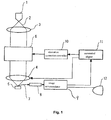
- Fig. 1 shows the configuration of an apparatus according to one embodiment of the present invention. Like components are indicated by like reference numerals in both Figs. 1 and 7.
- an emitter 1 emits an electron beam (or, a charged-particle beam) 2.
- a lens 3 acts on the beam 2.
- An aberration corrector 6 performs various corrections on the electron beam 2 undergoing a lens action from the lens 3.
- An objective lens 4 focuses the beam 2 onto a sample 5. Secondary electrons 7 are released from the sample 5.
- a secondary electron detector 8 detects the secondary electrons 7.
- An image accumulator 9 accumulates images to obtain a secondary electron image in which noise has been reduced.
- An aberration correction controller 10 supplies control signals to the aberration corrector 6 to correct aberrations.
- An automated aligner 11 supplies an automated alignment control signal to the aberration correction controller 10 or to the objective lens 4.
- a computer is used as the automated aligner 11.
- a CRT (display device) 12 is connected with the image accumulator 9 to display various information.
- a particle having a circular cross-sectional contour such as a spherical particle can be used as the sample 5.
- the controllability of the automated aligner 11 is improved if a spherical particle of gold or resin is used. The operation of the apparatus constructed in this way is described below.
- the electron beam 2 is emitted from the emitter 1.
- the lens 3 controls the electron beam 2 incident on the aberration corrector 6.
- the beam 2 transmitted through the corrector 6 is focused onto the surface of the sample 5 by the lens action of the objective lens 4.
- the beam 2 is scanned across the surface of the sample.
- Secondary electrons 7 emitted from the surface of the sample 5 in synchronism with the scanning are detected by the secondary electron detector 8.
- the secondary electrons are displayed as a SEM image on the CRT 12 in synchronism with the scan signal. Since the effective signals of the secondary electrons detected by the secondary electron detector 8 are normally low, noise in the signals is removed by the image accumulator 9.
- the aberration correction controller 10 controls the lens strength (focusing strength) of the aberration corrector 6.
- the automated aligner 11 obtains a SEM image from the image accumulator 9 and calculates a lens strength for correcting axial deviation of the aberration corrector 6.
- the aligner also calculates a lens strength of the multi-pole stages of the aberration corrector 6 for correcting the trajectory of the beam 2 in the aberration corrector 6 into a desired trajectory by means of the aberration corrector 6. After the calculations, the aligner 11 gives instructions to the aberration correction controller 10.
- the structure and operation of the aberration corrector 6 are described in detail in the above-cited non-patent reference 1.
- the structure and operation of the automated aligner 11 according to a preferred embodiment of the present invention are hereinafter described in detail by referring to Fig. 2.
- Fig. 2 shows an example of configuration of the automated aligner 11.
- This aligner 11 has an alignment controller 11a producing a control signal ⁇ Vn for alignment control.
- a beam profile extractor 11b that is a device for obtaining information about a cross section of the beam receives the output from the alignment controller 11, receives the SEM image 20, and obtains information about the cross sectionof the beam.
- the beamprofile extractor 11b outputs information about the beam profile 13 that is one kind of information about the beam cross section.
- An axial deviation quantification device 11c receives the beam profile 13 and quantifies the axial deviation of the optical axis of the electron beam 2 relative to the center of the multi-pole field in the aberration corrector 6.
- a decision unit 11e receives the output value from the axial deviation quantification device 11c and makes a decision as to whether feedback control is provided.
- a feedback unit 11d receives the output from the decision unit 11e and outputs a feedback control signal Vn. The operation of the apparatus constructed in this way in accordance with the present invention is next described.
- the automated aligner 11 gives instructions to the aberration correction controller 10 to vary the strengths of plural di-pole fields produced by multi-pole elements constituting the aberration corrector 6 to check the amount of axial deviation of the aberration corrector 6. Furthermore, the aligner 11 gives instructions to the aberration correction controller 10 to vary the strengths of lenses produced by plural multi-pole elements constituting the aberration corrector 6 for checking whether the electron beam 2 is in a given trajectory inside the corrector 6.
- the beam profile extractor 11b gains a SEM image when there is no change in the lens strengths and a SEM image when there is any change in the lens strengths in synchronism with the control signal ⁇ Vn from the alignment controller 11a for giving an instruction to vary the lens strengths, and calculates the beam profile (cross-sectional shape of the beam).
- a method of extracting the beam profile from the two SEM images is described in detail in WO 01/56057 AL. The method is described briefly herein.
- g1 be a SEM image produced when the strength of a lens is varied.
- g0 be a SEM image produced when the strength of the lens is not varied.
- s be the transfer function of the sample surface.
- p1 be the beam profile when the lens strength is varied.
- p0 be the beam profile when the lens strength is not varied.
- Eqs. (3) and (4), showing below, are obtained by Fourier-transforming of Eqs. (1) and (2).
- G 1 S ⁇ P 1
- G 0 S ⁇ P 0 where • indicates a product in a Fourier space.
- Capital letters indicate results of Fourier transforms.
- Eq. (5) showing below, is obtained by eliminating S from Eqs. (3) and (4).
- G 1 ( P 1 ⁇ G 0 / P 0 )
- the beam profile g0 produced when there is no change in the beam strength is a function showing a Gaussian distribution. Since G0 is also a Gaussian distribution function, beam profile 13 (g1) can be calculated. As shown in Fig. 2, the axial deviation quantification device 11c quantifies the present amount of the axial deviation from the obtained beam prof ile 13 (g1). A method of the quantification is illustrated in Fig. 3. The center of the field of view (FOV) is taken at the origin O. Let G be the center of gravity of the beam profile 13 which shows the distribution of electron densities (distribution of particle densities) in the beam cross section. A vector OG is projected onto the X- and Y-axes.
- Gx[ mode ] be the deviation in the X-direction.
- Gy [ mode ] be the deviation in the Y-direction.
- the geometric center of the outer periphery (contour) of the profile 13 can be used.
- Gx[ mode ] and Gy[ mode ] be functions of mode, which means discrimination of instructions from the alignment controller 11a.
- the feedback unit 11d calculates the amount of feedback Vn[ mode ] from the quantified amount of axial deviation Gx[mode] and Gy[mode] using the Eqs. (7-1) and (7-2).
- the aberration correction controller 10 orobjective lens 4 is informed of this amount of feedback Vn[ mode ].
- amount of feedback Vn indicates that it is a function of mode. Normally, the amount of feedback Vn has directionality.
- Vnx and Vny be the amounts of feedback in the X- and Y-directions, respectively.
- Vnx [ mode ] ⁇ [ mode ] ⁇ Gx [ mode ]
- Vny [ mode ] ⁇ [ mode ] ⁇ Gy [ mode ] where ⁇ [ mode ] and ⁇ [ mode ] are similarly functions of mode.
- automated alignment can be made using an aberration corrector by using the center of gravity or geometric center as the position of the beam profile of the electron beam (charged-particle beam).
- the decision unit 11e compares the amounts of axial deviations Gx[ mode ] and Gy [ mode ] discriminated using mode with their respective given threshold values. If the decision is that Gx and Gy are smaller than their threshold values, i.e., if the decision is that the axial deviation has been corrected, the correction is ended. If the decision is that the axial deviation has not been corrected sufficiently, the decision unit 11e instructs the alignment controller 11a to repeat these operations. As one method of control, if the following relations are satisfied by a threshold value ⁇ [mode] set for each mode, the control is judged to be ended.
- axial deviation can be corrected well by making axial deviation corrections on Gx and Gy independently. Furthermore, according to the invention, automated alignment may be repeated until the quantified amount of axial deviation falls below a given threshold value. Consequently, the amount of axial deviation can be reduced sufficiently. In this case, it is possible to make an automatic decision as to whether the trajectory of the electron beam has been corrected well by comparing the quantified amount of axial deviation with a given threshold value.
- FIG. 8 A diagram of the aberration corrector 6 composed of four stages of multi-pole elements and the trajectory of the electron beam 2 passing through the corrector 6 are shown in Fig. 8.
- the four stages of multi-pole elements are shown to comprise first multi-pole elements 6a, second multi-pole elements 6b, third multi-pole elements 6c, and fourth multi-pole elements 6d.
- each stage of multi-pole elements has 8 or more multi-pole elements.
- each stage of multi-pole elements consists of 12 multi-pole elements.
- the beam 2 undergoes a focusing action and a dispersing action simultaneously from the first multi-pole elements.
- the electron beam 2 that has undergone the dispersing action is in X trajectory 6e and that the electron beam 2 that has undergone the focusing action is in Y trajectory 6f.
- the lens strength of the first multi-pole elements 6a is so adjusted that the Y trajectory 6f passes through the center of the multi-pole field (lens field) produced by the second multi-pole elements 6b and becomes focused.
- the lens strength of the multi-pole elements 6b is so adjusted that the X trajectory 6e passes through the center of the multi-pole field (lens field) produced by the third multi-pole elements 6c and becomes focused.
- the Y trajectory 6f passes through the center of the multi-pole field produced by the second multi-pole elements 6b and thus is not affected by the multi-pole field produced by the second multi-pole elements 6b. Only the X trajectory 6e undergoes the lens action.
- the X trajectory 6e passes through the center of the multi-pole field (lens field) produced by the multi-pole element 6c and becomes focused. Therefore, the X-trajectory is not affected. Only the Y trajectory 6f undergoes the lens action. In this way, the Y trajectory 6f of the electron beam 2 must pass through the center of the multi-pole field produced by the multi-pole elements 6b and becomes focused. The X trajectory 6e must pass through the center of the multi-pole field produced by the multi-pole elements 6c and be focused.
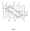
- Fig. 4 illustrates a case where the electron beam has been shifted out of its trajectory by varying the lens strength of the first stage of multi-pole elements.
- the electron beam 2 passes through the center of the multi-pole field produced by the second multi-pole elements 6b and passes through the center of the multi-pole field produced by the third multi-pole elements 6c.
- the X trajectory 6e is not focused into the center of the multi-pole field produced by the third multi-pole elements 6c.
- the Y trajectory 6f is not focused into the center of the multi-pole field produced by the second multi-pole fields 6b.
- the tilt and position of the electron beam 2 passed through the aberration corrector 6 vary. It follows that the obtained image blurs. Furthermore, the obtained image moves when the lens strength of each stage of multi-pole elements is varied unless the beam 2 passes through the centers of the multi-pole fields produced by the stages of multi-pole fields. In the technique disclosed in the above-cited non-patent reference 1, the beam 2 is controlled by the quadru-pole field contained in the multi-pole fields produced by the stages of multi-pole fields.
- the center of the quadru-pole field in the multi-pole fields produced by the first stage of multi-pole elements 6a can be found by (A) wobbling (i.e., varying, oscillating or fluctuating) the quadru-pole field contained in the multi-pole fields produced by the first stage of multi-pole elements 6a, (B) controlling the beam 2 with a deflector (not shown) on the side of the electron source of the aberration corrector 6, and (C) searching for a point at which the image does not move.
- the center of the quadru-pole field produced by the second stage of multi-pole elements 6b can be found by (A) wobbling (i.e. , varying, oscillating or fluctuating) the quadru-pole field produced by the second stage of multi-pole elements 6b, (B) controlling the electron beam 2 by the di-pole field (equivalent to deflection by a deflector) produced by the first stage of multi-pole elements 6a, and (C) searching for a point at which the image does not move.
- the center of the quadru-pole field produced by the third stage of multi-pole elements 6c and the center of the quadru-pole field produced by the fourth stage of multi-pole elements 6d can be searched for.
- the center of the lens field produced by the objective lens 4 can be searched for by wobbling (i.e., varying, oscillating or fluctuating) the strength of the objective lens 4 and using the di-pcle field produced by the fourth stage of multi-pole elements 6d.
- these operations are performed by the automated aligner 11.
- an instruction is given to the aberration correction controller 10 such that the alignment controller 11a varies the strength of the quadru-pole field produced by the second stage of multi-pole elements 6b in a corresponding manner to ⁇ Vn in the automated aligner 11 shown in Fig. 2.
- the aberration correction controller 10 controls the aberration corrector 6 to achieve the contents of the instruction.
- the corrector 6 varies the multi-pole field produced by the second stage of multi-pole elements 6b in a corresponding manner to ⁇ Vn. As a result, the SEM image shifts.
- the beam profile extractor 11b receives the shifted SEM image, as well as the SEM image produced when the lens strength was not varied.
- the extractor 11b calculates the beam profile 13.
- the axial deviation quantification device 11c quantifies the amount of axial deviation.
- the feedback unit 11d calculates the amount of feedback provided by the first stage of multi-pole elements 6a to the di-pole field and gives an instruction to the aberration corrector 6 or to the objective lens 4.
- the decision unit 11e gives an instruction to the alignment controller 11a to repeat the correction operations until the quantified amount of axial deviation satisfies Eq. (8).
- the X trajectory must be focused into the center of the multi-pole field produced by the third stage of multi-pole elements 6c.
- the Y trajectory must be focused into the center of the multi-pole field produced by the second stage of multi-pole elements 6b.
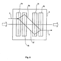
- the trajectory of the electron beam is shown in the X-Z plane and the Y-Z plane in Figs. 9a and 9b.
- the X trajectory is shown in Fig. 9a.
- the Y trajectory is shown in Fig. 9b.
- the Y trajectory 6f is kept focused into the center of the multi-pole field produced by the second multi-pole elements 6b by adjusting the strengths of the lens fields produced by the stages of multi-pole fields or lens field produced by the objective lens such that the SEM image does not move even if the strength of the di-pole field produced by the second stage of multi-pole elements 6b is varied in a corresponding manner to ⁇ Vn.
- the SEM image can be fixed by adjusting the quadru-pole field produced by the first stage of multi-pole elements 6a in this way.
- a multi-pole field produced by multi-pole elements exerts a focusing action and a diverging action on the electronbeam 2 simultaneously, affecting the X and Y axes. Therefore, the multi-pole fields produced by all the stages of multi-pole elements or the lens field produced by the objective lens must be adjusted finally.
- the same theory applies to the case where the X trajectory 6e is focused into the center of the multi-pole field produced by the third multi-pole elements 6c. That is, the strengths of the multi-pole fields produced by the stages of multi-pole elements or the strength of the lens field produced by the objective lens is adjusted such that the SEM image does not shift if the di-pole field produced by the third stage of multi-pole elements 6c is varied.
- these operations are performed by the automated aligner 11.
- an instruction is given to the aberration correction controller 10 such that the alignment controller 11a varies the strength of the di-pole field in the Y-direction produced by the second stage of multi-pole elements 6b in a corresponding manner to ⁇ Vn in the automated aligner 11 shown in Fig. 2.
- the aberration correction controller 10 controls the aberration corrector 6 to achieve the contents of the instruction.
- the aberration corrector 6 varies the strength of the di-pole field in the Y-direction produced by the second stage of multi-pole elements 6b in a corresponding manner to ⁇ Vn.
- the beam profile extractor 11b receives the shifted SEM image, as well as a SEM image produced when the strength was not varied.
- the extractor 11b extracts the beam profile 13.
- the axial deviation quantification device 11c quantifies the amount of axial deviation.
- the feedback unit 11d calculates the amount of feedback to the multi-pole fields produced by the stages of multi-pole elements or to the lens field produced by the objective lens.
- the feedback unit then gives an instruction to the aberration correction controller 10 or to the objective lens.
- the decision unit 11e gives an instruction to the alignment controller 11a such that it repeats the correction operations until the quantified amount of axial deviation satisfies Eq. (8).
- an image of a surface of a sample can be obtained under the condition where a lens strength has been varied. Furthermore, the amount of axial deviation of the apparatus can be found by using one or two extracted beam profiles (i.e., information about the beam cross section) of a charged-particle beam and multiplying the difference between the position of the center of gravity and the origin by a certain constant. Moreover, the amount of axial deviation of the apparatus can be found by using one or two extracted beam profiles of the charged-particle beam and multiplying the difference between the position of the center and the origin by a certain constant. Further, according to the invention, automated alignment can be performed using an aberration corrector by obtaining an amount of axial deviation, multiplying the amount of axial deviation by a certain constant, and applying feedback to the aberration corrector or objective lens according to the calculated product.
- one or two extracted beam profiles i.e., information about the beam cross section
- the amount of axial deviation of the apparatus can be found by using one or two extracted beam profiles of the charged-particle beam and multiplying the difference
- the automated aligner 11 performs plural alignments, which are discriminated using the value of mode, for example, as described below.
- the focal point of the Y trajectory can be moved near the center of the multi-pole field produced by the second stage of multi-pole elements 6b while the X trajectory is kept focused in the center of the multi-pole field produced by the third stage of multi-pole elements 6c, by fixing the ratio of the applied lens strengths of the quadru-pole fields produced by the first, second, and third stages of multi-pole fields at Ay:By:Cy.
- Ay ⁇ Vny is applied to the quadru-pole field produced by the first stage of multi-pole elements 6a.
- ⁇ Vny is applied to the quadru-pole field produced by the second stage of multi-pole elements 6b.
- Cy ⁇ Vny is applied to the quadru-pole field produced by the third stage of multi-pole elements 6c.
- the lens strength ratio is 4:-1:-1, for example. However, the invention is not limited to this ratio.
- the lens strength ratio of the quadru-pole field produced by the first stage of multi-pole elements 6a is experimentally set toAy
- the lens strengths of the quadru-pole field produced by the second stage of multi-pole elements 6b and the quadru-pole field produced by the third stage of multi-pole elements 6c may be set to By and Cy, respectively, such that the image is again focused.
- the focal point of the X trajectory can be moved near the center of the multi-pole field produced by the third stage of multi-pole elements 6c while maintaining the Y trajectory in focus at the center of the multi-pole field produced by the second stage of multi-pole elements 6b, by fixing the applied lens strength ratio of the quadru-pole fields produced by the second, third, and fourth stages of multi-pole elements to Bx:Cx:Dx.
- Bx ⁇ Vnx, Cx ⁇ Vnx, and Dx ⁇ Vnx are applied respectively to the quadru-pole fields produced by the second, third, and fourth stages of multi-pole elements 6b, 6c, and 6d, respectively.
- the lens strength ratio is -1:-1:4, for example, although the invention is not limited to this.
- the lens strengths of the quadru-pole field produced by the fourth stage of multi-pole elements 6d may be set to Bx and Cx, respectively, such that the image is again focused.
- Another method of focusing the X trajectory into the center of a multi-pole field produced by the third stage of multi-pole elements 6c is as follows.
- the focal point of the X trajectory can be moved near the center of the multi-pole field produced by the third stage of multi-pole elements 6d while maintaining the Y trajectory in focus in the center of the multi-pole field produced by the second stage of multi-pole elements 6b by fixing the lens strength ratios of the quadru-pole fields produced by the second and third stages of multi-pole elements at Bx:Cx.
- the image is out of focus at the sample position.
- a correction can be made by adjusting the strength of the lens field produced by the objective lens 4 in order to make the image come into focus again.
- the strength of the quadru-pole field produced by the second stage of multi-pole elements 6b, the strength of the quadru-pole field produced by the third stage of quadru-pole field, and the strength of the applied lens field produced by the objective lens are fixed at Bx:Cx:Ox and feedback is provided to them.
- Bx ⁇ Vnx, Cx ⁇ Vnx, and Ox ⁇ Vnx are applied respectively to the quadru-pole field produced by the second stage of quadru-pole multi-pole elements 6b, the quadru-pole field produced by the third stage of multi-pole elements 6c, and the lens field produced by the objective lens.
- the lens strength ratio is -1:1:Ox, for example, though the invention is not limited to this ratio.
- the lens strengths of the quadru-pole field produced by the second stage of multi-pole elements 6b and the quadru-pole field produced by the third stage of multi-pole elements 6c may be set to Bx and Cx, respectively, such that the image is again focused.
- automated alignment can be performed using an aberration corrector by using two, three, or five sample surface images. Furthermore, automated alignment can be performed with an aberration corrector using an image obtained under the condition where the lens strength of the aberration corrector is shifted by a given amount as well as an image obtained under the present value. Furthermore, automated alignment can be performed with an aberration corrector using an image obtained under the condition where a lens strength of the aberration corrector has been shifted in the X- and Y-directions by given amounts as well as an image obtained under the present value. In addition, automated alignment can be performed with an aberration corrector consisting of four stages of multi-pole elements.
- automated alignment can be performed with an aberration corrector consisting of four stages of multi-pole elements each of which has four or more poles.
- each of the multi-pole elements constituting the aberration corrector has 12 poles.
- Automated alignment can also be performed with an aberration corrector consisting of four stages of multi-pole elements each of which is a di-pole element, quadru-pole element, hexa-pole element, or octu-pole element.
- a normal operator can perform automated corrections of alignment of an aberration corrector unconsciously of the corrector.
- the present amount of axial deviation may be quantified and so the apparatus can assist the operator by displaying the state of operation of the automated aligner 11 (e.g., the histories of the beam profile 13 and the amount of axial deviation of the apparatus on the graphical user interface (GUI) 15 on the CRT 12 as shown in Fig. 6).
- the FOV of the beam profile is indicated by 14.
- Gx in the figure shows that the amount of axial deviation decreases gradually with increasing the number of trials.
- Gy indicates that the amount of axial deviation increases after a lapse of a certain time and then decreases.
- the method of automatically correcting a charged-particle beam in accordance with the present invention comprises the steps of: irradiating a sample with the charged-particle beam via an aberration corrector and an objective lens, the aberration corrector having multi-pole elements; obtaining information about a cross section of the charged-particle beam based on plural images of a surface of the irradiated sample; calculating an amount of axial deviation of the optical axis of the beam relative to the center of a multi-pole field in the aberration corrector based on the obtained information about the cross section of the beam; and automatically applying feedback to the aberration corrector or to the objective lens according to the calculated amount of axial deviation.
- the apparatus for automatically correcting a charged-particle beam in accordance with the present invention comprises: an aberration corrector having multi-pole elements; means for obtaining information about a cross section of the charged-particle beam based on plural images of a surface of a sample irradiated with the beam via the aberration corrector and an objective lens; means for calculating an amount of axial deviation of the optical axis of the beam relative to the center of a multi-pole field in the aberration corrector based on the obtained information about the cross section of the beam; and feedback means for automatically applying feedback to the aberration corrector or to the objective lens according to the calculated amount of axial deviation.
- the number of used images of a surface of a sample may be any one of two, three, and five.
- a first one of the images can be obtained when the lens strength of the aberration corrector is set to a first value, and a second one of the images can be obtained when the lens strength is set to a second value shifted from the first value by a given amount.
- a first one of the images can be obtained when the lens strength of an aberration corrector is set to a first value
- a second one of the images can be obtained when the lens strength is set to a second value shifted from the first value by a first given amount in an X-direction
- a third one of the images can be obtained when the lens strength is set to a third value shifted from the first value by a second given amount in a Y-direction.
- a first one of the images can be obtained when the lens strength of the aberration corrector is set to a first value
- a second one of the images can be obtained when the lens strength is set to a second value shifted from the first value by a first positive given amount in an X-direction
- a third one of the images can be obtained when the lens strength is set to a third value shifted from the first value by a second negative given amount in the X-direction
- a fourth one of the images can be obtained when the lens strength is set to a fourth value shifted from the first value by a third positive given amount in a Y-direction
- a fifth one of the images can be obtained when the lens strength is set to a fifth value shifted from the first value by a fourth negative given amount in the Y-direction.
- the aberration corrector can be equipped with four stages of multi-pole elements.
- each stage of the four stages of multi-pole elements constituting the aberration corrector can be equipped with four or more multi-pole elements.
- the aberration corrector can be equipped with four stages of multi-pole elements.
- Suite of di-pole field produced by the stages of multi-pole elements in the aberration corrector, quadru-pole field produced by the stages of multi-pole elements, hexa-pole field produced by the stages of multi-pole elements, octu-pole field produced by the stages of multi-pole elements, and lens field produced by the objective lens can be shifted in strengths.
- An image of the surface of the sample can also be obtained simultaneously with variation of the strength of any one of the fields.
- the amount of axial deviation can be calculated by multiplying the difference between the center of gravity of the distribution of particle densities contained in the obtained information about one or two cross sections and the position of the origin contained in the information about the cross sections by a constant value.
- the amount of axial deviation can be calculated by multiplying the difference between the center position of the cross-sectional contour of the beam contained in the obtained information about one or two cross sections and the position of the origin contained in the information about the cross sections by a constant value.
- feedback may be applied to the aberration corrector or to the objective lens in proportion to the obtained amount of axial deviation.
- the aberration corrector can be equipped with four stages of multi-pole elements. Feedback can be applied to any one of di-pole field produced by the stages of multi-pole elements in the aberration corrector, quadru-pole field produced by the stages of multi-pole elements, and lens field produced by the objective lens.
- a decision as to whether the optical axis of the charged-particle beam has been corrected so as to enter a given range can be automatically made by comparing the amount of axial deviation with a threshold value.
- the processing for automated correction can be repeated until the amount of axial deviation falls below the threshold value.
- the sample can be a reference sample.
- the sample can be made movable between a first position in a sample chamber where the sample is irradiated with the beam and a second position where the sample is on standby for transfer to the first position.
- the sample can be a particle having a circular cross-sectional contour.
- the sample can be a spherical particle made of gold or resin.
- the axial deviation can be corrected in X- and Y-directions independently.
- the obtained information about the cross section of the charged-particle beam and the calculated amount of axial deviation can be displayed.
- Another apparatus for automatically correcting a charged-particle beam in accordance with the present invention comprises: an aberration corrector equipped with multi-pole elements and acting to correct aberration in the charged-particle beam; an aberration correction controller for controlling the strength of a multi-pole field produced by the aberration corrector; an objective lens; a control unit for supplying a control signal to the aberration correction controller or to the objective lens; cross-sectional information-obtaining device for obtaining a SEM image in synchronism with operation of the control unit and obtaining information about a cross section of the charged-particle beam; an axial deviation quantification device for quantifying the amount of the axial deviation of the optical axis of the beam from the obtained information about the cross section of the beam; a decision unit for making a decision from the quantified amount of axial deviation as to whether automated correction is made; and a feedback device for outputting an amount of feedback to the aberration correction controller or to the objective lens from the quantified amount of axial deviation.
- the aberration corrector is made up of plural stages of multi-pole elements.
- a control unit controls the whole aberration corrector as a single lens. During this control, the lens strength ratio of the stages of multi-pole lenses is kept constant.
- the aberration corrector is made up of plural stages of multi-pole elements.
- a control unit controls the whole aberration corrector as a single lens. During this control, the lens strength ratio of the stages of multi-pole lenses and objective lens is kept constant.
- Feedback may be applied by the control unit either to a lens formed in such a way that the lens strength ratio of the stages of multi-pole elements in the aberration corrector is kept constant or to a lens formed in such a way that the lens strength ratio of the stages of multi-pole elements and objective lens is kept constant.
Landscapes
- Chemical & Material Sciences (AREA)
- Analytical Chemistry (AREA)
- Electron Sources, Ion Sources (AREA)
Abstract

Description
- The present invention relates to a method and apparatus for automatically correcting aberration in a charged-particle beam and also to a method of controlling an aberration corrector for a charged-particle beam.
- A scanning electron microscope (SEM) is an example of a surface imaging apparatus using charged particles. The surface imaging apparatus is described, taking a scanning electron microscope as an example. Fig. 7 is a diagram showing an example of structure of the prior art apparatus. Fig. 7 shows a scanning electron microscope equipped with an aberration corrector. The microscope has an emitter 1 emitting an
electron beam 2. Trajectory of thebeam 2 incident on theaberration corrector 6 is controlled by alens 3 acting on thebeam 2. Thebeam 2 transmitted through thecorrector 6 is focused onto the surface of asample 5 by anobjective lens 4. At this time, theaberration corrector 6 corrects the aberration of the total lens system. - The sample surface is scanned with the electronbeam2.
Secondary electrons 7 are emitted from the sample surface in synchronism with the scanning and are detected by asecondary electron detector 8. Information about the sample surface based on the detectedsecondary electrons 7 is displayed as a visible image on aCRT 12 in synchronism with the scan signal. Normally, the efficiency of thesecondary electron detector 8 which detectssecondary electrons 7 is low. Therefore, noise is removed by animage accumulator 9. The image from which the noise has been removed in this way is displayed on theCRT 12. An aberration corrector equipped with multi-pole elements is known as an example of such aberration corrector 6 (see, for example, non-patent reference 1). - The technique disclosed in non-patent reference 1 is described below as an example. Fig. 8 is a diagram showing the configuration of an aberration corrector and the trajectory of an electron beam passing through the corrector. In Fig. 8, the aberration corrector, indicated by
numeral 6, has four stages of multi-pole elements, which are shown respectively as firstmulti-pole elements 6a, secondmulti-pole elements 6b, thirdmulti-pole elements 6c, and fourthmulti-pole elements 6d. Normally, each stage of multi-pole elements has eight or more pole elements. Theelectron beam 2 incident on theaberration corrector 6 undergoes a focusing action and a diverging action simultaneously by the lens action of the firstmulti-pole elements 6a. As shown, it is assumed that theelectron beam 2 that has undergone the diverging action is in anX trajectory 6e and that thebeam 2 that has undergone the focusing action is in aY trajectory 6f. - The lens strength of the first
multi-pole elements 6a is so adjusted that theY trajectory 6f passes through the center of a lens field produced by the secondmulti-pole elements 6b and is focused in the Y-direction. The lens strength of the secondmulti-pole elements 6b is so adjusted that theX trajectory 6e passes through the center of a lens field produced by the thirdmulti-pole elements 6c and is focused in the X-direction. At this time, in the secondmulti-pole elements 6b, theY trajectory 6f passes through the center of the lens field produced by the secondmulti-pole elements 6b and is focused in the Y-direction and so only theX trajectory 6e undergoes the lens action of the secondmulti-pole elements 6b. Similarly, in the thirdmulti-pole elements 6c, thetrajectory 6e passes through the center of the lens field produced by the thirdmulti-pole elements 6c and is focused in the X-direction. Therefore, only theY trajectory 6f undergoes the lens action of the thirdmulti-pole elements 6c. In this way, the requirement is that theY trajectory 6f of theelectron beam 2 is focused on and passes through the center of the lens field produced by the secondmulti-pole elements 6b and theX trajectory 6e of thebeam 2 is focused on and passes through the center of the lens field produced by the thirdmulti-pole elements 6c. - In the prior art, these corrections (alignments) of the trajectories of the electron beam have been made by adjusting the lens strengths of the plural stages of
multi-pole elements 6a-6d while viewing the amount of movement of the image produced when the lens strengths of the stages ofmulti-pole elements 6a-6d are wobbled (i.e., varied, oscillated or fluctuated). - Inparticular, there are mechanical deviations among the center axes of the various stages of
multi-pole elements 6a-6d. It is difficult to correct these mechanical deviations of the center axes among the stages ofmulti-pole elements 6a-6d by adjusting the mechanical positions of the stages ofmulti-pole elements 6a-6d. Accordingly, the conventional method is to adjust the lens field strength electrically produced by the stages ofmulti-pole elements 6a-6d to the appropriate electron beam pass. Consequently, substantial hindrance is prevented even if there are mechanical positional deviations among the stages ofmulti-pole elements 6a-6d. - The lens fields produced by the stages of
multi-pole elements 6a-6d contain di-pole and quadru-pole fields. When the di-pole field produced by the multi-pole elements to be adjusted is adjusted, the quadru-pole field produced by the multi-pole elements located behind the multi-pole elements to be adjusted is made to wobble (i.e., vary, oscillate or fluctuate). The di-pole field produced by the multi-pole elements to be adjusted is adjusted such that the image taken during the wobbling does not move. In this way, the trajectory of the electron beam is aligned. - As described previously, it is necessary that the
Y trajectory 6f of thebeam 2 is focused on and passes through the center of the lens field produced by the secondmulti-pole element 6b and theX trajectory 6e of thebeam 2 is focused on and passes through the center of the lens field produced by the thirdmulti-pole element 6c. To achieve this requirement, the quadru-pole fields produced by the stages ofmulti-pole elements 6a-6d need to be adjusted. During this adjustment, the di-pole field produced by the multi-pole elements located next to the multi-pole elements to be adjusted is made to wobble (i.e., vary, oscillate or fluctuate). The quadru-pole field produced by the multi-pole elements to be adjusted are adjusted such that the image obtained during the wobbling of the di-pole field does not shift. In this way, the trajectory of the electron beam pass is aligned. - The procedure of adjustment of the di-pole field produced by the aforementioned multi-pole elements is linked to the procedure of adjustment of the quadru-pole fields produced by the other multi-pole elements such that the electron beam trajectory adjusted by one of these two kinds of fields is affected by adjustment of the other kind of field. Therefore, the operator has spent a long time in adjusting the lens field (multi-pole field) of each multi-pole element while checking the motion and quality of the image during wobbling, relying on his experience and intuition.
- [Non-patent reference 1] Aberration correction in a lowvoltage SEMbymulti-pole corrector (Nuclear Instrument and Methods in Physics Research, A 363 (1995), 316-325)
- As described previously, in the aberration corrector composed of multiple stages of multi-pole elements, there are deviations among the mechanical center axes of the stages of multi-pole elements. By adjusting the multi-pole fields (di-pole and quadru-pole fields) produced by the stages of multi-pole elements by the aforementioned method (i.e., given multi-pole field produced by the multi-pole elements located behind the multi-pole elements to be adjusted is made to wobble (i.e., vary, oscillate or fluctuate)), the operator empirically aligns the trajectory of the electron beam such that the beam is focused and passes through the center of the corresponding stages of multi-pole elements within the aberration corrector.
- To achieve this, the operator manually adjusts and corrects the lens strengths of the stages of multi-pole elements. These procedural operations are complexly linked. There is the problem that the operator spends a lot of time in making the manual adjustment according to the movement and quality of the image while relying on his experience and intuition.
- In view of the foregoing problem, the present invention has been made. It would be desirable to provide a method and apparatus for automatically correcting the trajectory of a charged-particle beam without a normal operator manually adjusting an aberration corrector. It would also be desirable to provide a method of controlling an aberration corrector for a charged-particle beam.
- A method of automatically correcting a charged-particle beam in accordance with the invention comprises the steps of: irradiating a sample with the charged-particle beam via an aberration corrector and an objective lens, the aberration corrector having multi-pole elements; obtaining information about a cross section of the charged-particle beam based on plural images of a surface of the irradiated sample; calculating an amount of axial deviation of the optical axis of the charged-particle beam relative to the center of a multi-pole field in the aberration corrector based on the obtained information about the cross section of the beam; automatically applying feedback to the aberration corrector or to the objective lens according to the calculated amount of axial deviation.
- An apparatus for automatically correcting a charged-particle beam in accordance with the present invention comprises: cross-sectional information-obtaining means for obtaining information about a cross section of the charged-particle beam based on plural images of a surface of a sample irradiated with the beam via an aberration corrector and via an objective lens, the corrector being equipped with multi-pole elements; calculation means for calculating an amount of axial deviation of the optical axis of the beam relative to the center of a multi-pole field in the aberration corrector based on the obtained information about the cross section of the beam; and feedback means for automatically applying feedback to the aberration corrector or to the objective lens according to the calculated amount of axial deviation.
- Another apparatus for automatically correcting a charged-particle beam in accordance with the present invention comprises: an aberration corrector for correcting aberration in the beam, the corrector being equipped with multi-pole elements; an aberration correction controller for controlling the strength of a multi-pole field produced by the aberration corrector; an objective lens; a control unit for supplying a control signal to the aberration correction controller or to the objective lens; a cross-sectional information-obtaining device for obtaining a SEM image in synchronism with operation of the control unit to obtain information about a cross section of the beam; an axial deviation quantification device for obtaining a quantified amount of the axial deviation of the optical axis of the beam from the obtained information about the cross section of the beam; a decision unit for making a decision from the quantified amount of axial deviation as to whether an automated correction is completed or not; and a feedback device for producing an amount of feedback to the aberration correction controller or to the objective lens from the quantified amount of axial deviation.
- In the method of controlling the aberration corrector for the charged-particle beam, the corrector is made up of plural stages of multi-pole elements. The control unit controls the whole aberration corrector as a single lens. During the control operation, the ratio of the strengths of the lenses of the stages of multi-pole elements is kept constant.
- Furthermore, the invention provides another method of controlling an aberration corrector for a charged-particle beam, the corrector being made up of plural stages of multi-pole elements. In this method, a control unit controls the whole aberration corrector as a single lens. During the control operation, the ratio of the strengths of the lenses of the stages of multi-pole elements and the objective lens is kept constant.
- The method of automatically correcting a charged-particle beam in accordance with the present invention makes it possible for the operator to automatically correct the beam without relying on manual operations.
- The apparatus for automatically correcting a charged-particle beam in accordance with the present invention similarly permits automated correction of the beam without relying on operator's manual operations.
- According to the method of controlling an aberration corrector for a charged-particle beam in accordance with the present invention, the whole aberration corrector can be controlled as a single lens with one control signal by maintaining the ratio of the strengths of the lenses formed by the stages of multi-pole elements constant. Axial deviation can be corrected well by simplifying the control system.
- In addition, according to the other method of controlling an aberration corrector for a charged-particle beam in accordance with the present invention, the whole aberration corrector can be controlled as a single lens with one control signal by maintaining the ratio of the strengths of the stages of multi-pole lenses and objective lens constant. Axial deviation can be corrected well by simplifying the control system.
- Other preferred features of the invention will appear in the course of the description thereof, which follows.
-
- Fig. 1 is a diagram showing an apparatus according to one embodiment of the present invention;
- Fig. 2 is a diagram illustrating an example of configuration of an automated aligner;
- Fig. 3 is a diagram illustrating a method of quantification;
- Fig. 4 is a diagram illustrating a case in which an electron beam has shifted out of its appropriate trajectory;
- Fig. 5 is a diagram illustrating an trajectory of an electron beam;
- Fig. 6 is a diagram illustrating the manner in which a display is provided by a method according to one embodiment of the invention;
- Fig. 7 is a diagram showing an example of configuration of the prior art apparatus;
- Fig. 8 is a diagram showing the configuration of an aberration corrector and the trajectory of an electron beam passing through the corrector; and
- Fig. 9 is a diagram in which the trajectory of an electron beam is drawn on the X-Z and Y-Z planes.
- The preferred embodiments of the present invention are hereinafter described in detail with reference to the accompanying drawings.
- Fig. 1 shows the configuration of an apparatus according to one embodiment of the present invention. Like components are indicated by like reference numerals in both Figs. 1 and 7. In Fig. 1, an emitter 1 emits an electron beam (or, a charged-particle beam) 2. A
lens 3 acts on thebeam 2. Anaberration corrector 6 performs various corrections on theelectron beam 2 undergoing a lens action from thelens 3. Anobjective lens 4 focuses thebeam 2 onto asample 5.Secondary electrons 7 are released from thesample 5. Asecondary electron detector 8 detects thesecondary electrons 7. - An
image accumulator 9 accumulates images to obtain a secondary electron image in which noise has been reduced. Anaberration correction controller 10 supplies control signals to theaberration corrector 6 to correct aberrations. Anautomated aligner 11 supplies an automated alignment control signal to theaberration correction controller 10 or to theobjective lens 4. As an example, a computer is used as theautomated aligner 11. A CRT (display device) 12 is connected with theimage accumulator 9 to display various information. - In the present invention, a particle having a circular cross-sectional contour such as a spherical particle can be used as the
sample 5. In particular, the controllability of the automatedaligner 11 is improved if a spherical particle of gold or resin is used. The operation of the apparatus constructed in this way is described below. - The
electron beam 2 is emitted from the emitter 1. Thelens 3 controls theelectron beam 2 incident on theaberration corrector 6. Thebeam 2 transmitted through thecorrector 6 is focused onto the surface of thesample 5 by the lens action of theobjective lens 4. Thebeam 2 is scanned across the surface of the sample.Secondary electrons 7 emitted from the surface of thesample 5 in synchronism with the scanning are detected by thesecondary electron detector 8. Thus, the secondary electrons are displayed as a SEM image on theCRT 12 in synchronism with the scan signal. Since the effective signals of the secondary electrons detected by thesecondary electron detector 8 are normally low, noise in the signals is removed by theimage accumulator 9. - The
aberration correction controller 10 controls the lens strength (focusing strength) of theaberration corrector 6. Theautomated aligner 11 obtains a SEM image from theimage accumulator 9 and calculates a lens strength for correcting axial deviation of theaberration corrector 6. The aligner also calculates a lens strength of the multi-pole stages of theaberration corrector 6 for correcting the trajectory of thebeam 2 in theaberration corrector 6 into a desired trajectory by means of theaberration corrector 6. After the calculations, thealigner 11 gives instructions to theaberration correction controller 10. The structure and operation of theaberration corrector 6 are described in detail in the above-cited non-patent reference 1. The structure and operation of the automatedaligner 11 according to a preferred embodiment of the present invention are hereinafter described in detail by referring to Fig. 2. - Fig. 2 shows an example of configuration of the automated
aligner 11. Thisaligner 11 has analignment controller 11a producing a control signal ΔVn for alignment control. Abeam profile extractor 11b that is a device for obtaining information about a cross section of the beam receives the output from thealignment controller 11, receives theSEM image 20, and obtains information about the cross sectionof the beam. Thebeamprofile extractor 11b outputs information about thebeam profile 13 that is one kind of information about the beam cross section. An axialdeviation quantification device 11c receives thebeam profile 13 and quantifies the axial deviation of the optical axis of theelectron beam 2 relative to the center of the multi-pole field in theaberration corrector 6. Adecision unit 11e receives the output value from the axialdeviation quantification device 11c and makes a decision as to whether feedback control is provided. Afeedback unit 11d receives the output from thedecision unit 11e and outputs a feedback control signal Vn. The operation of the apparatus constructed in this way in accordance with the present invention is next described. - The
automated aligner 11 gives instructions to theaberration correction controller 10 to vary the strengths of plural di-pole fields produced by multi-pole elements constituting theaberration corrector 6 to check the amount of axial deviation of theaberration corrector 6. Furthermore, thealigner 11 gives instructions to theaberration correction controller 10 to vary the strengths of lenses produced by plural multi-pole elements constituting theaberration corrector 6 for checking whether theelectron beam 2 is in a given trajectory inside thecorrector 6. Thebeam profile extractor 11b gains a SEM image when there is no change in the lens strengths and a SEM image when there is any change in the lens strengths in synchronism with the control signal ΔVn from thealignment controller 11a for giving an instruction to vary the lens strengths, and calculates the beam profile (cross-sectional shape of the beam). A method of extracting the beam profile from the two SEM images is described in detail in WO 01/56057 AL. The method is described briefly herein. - Let g1 be a SEM image produced when the strength of a lens is varied. Let g0 be a SEM image produced when the strength of the lens is not varied. Let s be the transfer function of the sample surface. Let p1 be the beam profile when the lens strength is varied. Let p0 be the beam profile when the lens strength is not varied. The SEM images g1 and g0 are expressed respectively by


- Here, we set P1/P0 = P10. Inversely Fourier transforming Eq. (5) into a real space results in:

- As an example, it is assumed that the beam profile g0 produced when there is no change in the beam strength is a function showing a Gaussian distribution. Since G0 is also a Gaussian distribution function, beam profile 13 (g1) can be calculated. As shown in Fig. 2, the axial
deviation quantification device 11c quantifies the present amount of the axial deviation from the obtained beam prof ile 13 (g1). A method of the quantification is illustrated in Fig. 3. The center of the field of view (FOV) is taken at the origin O. Let G be the center of gravity of thebeam profile 13 which shows the distribution of electron densities (distribution of particle densities) in the beam cross section. A vector OG is projected onto the X- and Y-axes. Let Gx[mode] be the deviation in the X-direction. Let Gy [mode] be the deviation in the Y-direction. Instead of the center of gravity, the geometric center of the outer periphery (contour) of theprofile 13 can be used. - It is now assumed that Gx[mode] and Gy[mode] be functions of mode, which means discrimination of instructions from the
alignment controller 11a. For example, "mode = 1" means that the quadru-pole field produced by the first multi-pole elements of theaberration corrector 6 has been varied. Thefeedback unit 11d calculates the amount of feedback Vn[mode] from the quantified amount of axial deviation Gx[mode] and Gy[mode] using the Eqs. (7-1) and (7-2). Theaberration correction controller 10orobjective lens 4 is informed of this amount of feedback Vn[mode]. Similarly, amount of feedback Vn indicates that it is a function of mode. Normally, the amount of feedback Vn has directionality. Let Vnx and Vny be the amounts of feedback in the X- and Y-directions, respectively.

- In this way, according to the present invention, automated alignment can be made using an aberration corrector by using the center of gravity or geometric center as the position of the beam profile of the electron beam (charged-particle beam).
- The
decision unit 11e compares the amounts of axial deviations Gx[mode] and Gy [mode] discriminated using mode with their respective given threshold values. If the decision is that Gx and Gy are smaller than their threshold values, i.e., if the decision is that the axial deviation has been corrected, the correction is ended. If the decision is that the axial deviation has not been corrected sufficiently, thedecision unit 11e instructs thealignment controller 11a to repeat these operations. As one method of control, if the following relations are satisfied by a threshold value γ [mode] set for each mode, the control is judged to be ended.
- According to the present invention, axial deviation can be corrected well by making axial deviation corrections on Gx and Gy independently. Furthermore, according to the invention, automated alignment may be repeated until the quantified amount of axial deviation falls below a given threshold value. Consequently, the amount of axial deviation can be reduced sufficiently. In this case, it is possible to make an automatic decision as to whether the trajectory of the electron beam has been corrected well by comparing the quantified amount of axial deviation with a given threshold value.
- A diagram of the
aberration corrector 6 composed of four stages of multi-pole elements and the trajectory of theelectron beam 2 passing through thecorrector 6 are shown in Fig. 8. The four stages of multi-pole elements are shown to comprise firstmulti-pole elements 6a, secondmulti-pole elements 6b, thirdmulti-pole elements 6c, and fourthmulti-pole elements 6d. Normally, each stage of multi-pole elements has 8 or more multi-pole elements. In the present embodiment, each stage of multi-pole elements consists of 12 multi-pole elements. According to the above-cited non-patent reference 1, thebeam 2 undergoes a focusing action and a dispersing action simultaneously from the first multi-pole elements. - Referring to Fig. 8, it is assumed that the
electron beam 2 that has undergone the dispersing action is inX trajectory 6e and that theelectron beam 2 that has undergone the focusing action is inY trajectory 6f. The lens strength of the firstmulti-pole elements 6a is so adjusted that theY trajectory 6f passes through the center of the multi-pole field (lens field) produced by the secondmulti-pole elements 6b and becomes focused. The lens strength of themulti-pole elements 6b is so adjusted that theX trajectory 6e passes through the center of the multi-pole field (lens field) produced by the thirdmulti-pole elements 6c and becomes focused. At this time, in the second multi-pole elements, theY trajectory 6f passes through the center of the multi-pole field produced by the secondmulti-pole elements 6b and thus is not affected by the multi-pole field produced by the secondmulti-pole elements 6b. Only theX trajectory 6e undergoes the lens action. - Similarly, in the third multi-pole elements, the
X trajectory 6e passes through the center of the multi-pole field (lens field) produced by themulti-pole element 6c and becomes focused. Therefore, the X-trajectory is not affected. Only theY trajectory 6f undergoes the lens action. In this way, theY trajectory 6f of theelectron beam 2 must pass through the center of the multi-pole field produced by themulti-pole elements 6b and becomes focused. TheX trajectory 6e must pass through the center of the multi-pole field produced by themulti-pole elements 6c and be focused. Fig. 4 illustrates a case where the electron beam has been shifted out of its trajectory by varying the lens strength of the first stage of multi-pole elements. Theelectron beam 2 passes through the center of the multi-pole field produced by the secondmulti-pole elements 6b and passes through the center of the multi-pole field produced by the thirdmulti-pole elements 6c. However, theX trajectory 6e is not focused into the center of the multi-pole field produced by the thirdmulti-pole elements 6c. TheY trajectory 6f is not focused into the center of the multi-pole field produced by the secondmulti-pole fields 6b. - In this case, the tilt and position of the
electron beam 2 passed through theaberration corrector 6 vary. It follows that the obtained image blurs. Furthermore, the obtained image moves when the lens strength of each stage of multi-pole elements is varied unless thebeam 2 passes through the centers of the multi-pole fields produced by the stages of multi-pole fields. In the technique disclosed in the above-cited non-patent reference 1, thebeam 2 is controlled by the quadru-pole field contained in the multi-pole fields produced by the stages of multi-pole fields. When thebeam 2 does not pass through the center of the quadru-pole field produced by the multi-pole elements, the center of the quadru-pole field in the multi-pole fields produced by the first stage ofmulti-pole elements 6a can be found by (A) wobbling (i.e., varying, oscillating or fluctuating) the quadru-pole field contained in the multi-pole fields produced by the first stage ofmulti-pole elements 6a, (B) controlling thebeam 2 with a deflector (not shown) on the side of the electron source of theaberration corrector 6, and (C) searching for a point at which the image does not move. - The center of the quadru-pole field produced by the second stage of
multi-pole elements 6b can be found by (A) wobbling (i.e. , varying, oscillating or fluctuating) the quadru-pole field produced by the second stage ofmulti-pole elements 6b, (B) controlling theelectron beam 2 by the di-pole field (equivalent to deflection by a deflector) produced by the first stage ofmulti-pole elements 6a, and (C) searching for a point at which the image does not move. Similarly, the center of the quadru-pole field produced by the third stage ofmulti-pole elements 6c and the center of the quadru-pole field produced by the fourth stage ofmulti-pole elements 6d can be searched for. In addition, in order that theelectron beam 2 passed through theaberration corrector 6 passes through the center of the lens field produced by theobjective lens 4, the center of the lens field produced by theobjective lens 4 can be searched for by wobbling (i.e., varying, oscillating or fluctuating) the strength of theobjective lens 4 and using the di-pcle field produced by the fourth stage ofmulti-pole elements 6d. In the present invention, these operations are performed by the automatedaligner 11. For example, where the beam is passed through the center of the quadru-pole field produced by the second stage ofmulti-pole elements 6b, an instruction is given to theaberration correction controller 10 such that thealignment controller 11a varies the strength of the quadru-pole field produced by the second stage ofmulti-pole elements 6b in a corresponding manner to ΔVn in theautomated aligner 11 shown in Fig. 2. - The
aberration correction controller 10 controls theaberration corrector 6 to achieve the contents of the instruction. Thecorrector 6 varies the multi-pole field produced by the second stage ofmulti-pole elements 6b in a corresponding manner to ΔVn. As a result, the SEM image shifts. Thebeam profile extractor 11b receives the shifted SEM image, as well as the SEM image produced when the lens strength was not varied. Theextractor 11b calculates thebeam profile 13. The axialdeviation quantification device 11c quantifies the amount of axial deviation. Thefeedback unit 11d calculates the amount of feedback provided by the first stage ofmulti-pole elements 6a to the di-pole field and gives an instruction to theaberration corrector 6 or to theobjective lens 4. Thedecision unit 11e gives an instruction to thealignment controller 11a to repeat the correction operations until the quantified amount of axial deviation satisfies Eq. (8). - Additionally, the X trajectory must be focused into the center of the multi-pole field produced by the third stage of
multi-pole elements 6c. Also, the Y trajectory must be focused into the center of the multi-pole field produced by the second stage ofmulti-pole elements 6b. The trajectory of the electron beam is shown in the X-Z plane and the Y-Z plane in Figs. 9a and 9b. The X trajectory is shown in Fig. 9a. The Y trajectory is shown in Fig. 9b. A decision is made as to whether theY trajectory 6f is focused into the center of the multi-pole field produced by the second stage ofmulti-pole elements 6b depending on whether theelectron beam 2 is focused into the center of the di-pole field in the Y-direction in the multi-pole field produced by themulti-pole elements 6b. That is, when the strength of the di-pole field in the Y-direction produced by the second stage ofmulti-pole elements 6b is varied in a corresponding manner to ΔVn, if theY trajectory 6f is focused into the center of the di-pole fieldproducedby the secondmulti-pole elements 6b as shown in Fig. 5, theelectron beam 2 passed through theaberration corrector 6 is brought to a focus at one point on the surface of thesample 5 by theobjective lens 4 provided that the di-pole field varies in strength. Consequently, the obtained SEM image does not move. - However, if the
Y trajectory 6f is not focused into the center of the di-pole field produced by the secondmulti-pole elements 6b, anobject point 18 shown in Fig. 5 will move when the strength of the multi-pole field produced by the second stage ofmulti-pole elements 6b is varied in a corresponding manner to ΔVn. As a result, the SEM image will shift. That is, theY trajectory 6f is kept focused into the center of the multi-pole field produced by the secondmulti-pole elements 6b by adjusting the strengths of the lens fields produced by the stages of multi-pole fields or lens field produced by the objective lens such that the SEM image does not move even if the strength of the di-pole field produced by the second stage ofmulti-pole elements 6b is varied in a corresponding manner to ΔVn. - The SEM image can be fixed by adjusting the quadru-pole field produced by the first stage of
multi-pole elements 6a in this way. However, as shown in Fig. 4, a multi-pole field produced by multi-pole elements exerts a focusing action and a diverging action on theelectronbeam 2 simultaneously, affecting the X and Y axes. Therefore, the multi-pole fields produced by all the stages of multi-pole elements or the lens field produced by the objective lens must be adjusted finally. - The same theory applies to the case where the
X trajectory 6e is focused into the center of the multi-pole field produced by the thirdmulti-pole elements 6c. That is, the strengths of the multi-pole fields produced by the stages of multi-pole elements or the strength of the lens field produced by the objective lens is adjusted such that the SEM image does not shift if the di-pole field produced by the third stage ofmulti-pole elements 6c is varied. - In a preferred embodiment of the present invention, these operations are performed by the automated
aligner 11. As an example, when theY trajectory 6f is not focused on the center of the multi-pole field produced by the secondmulti-pole elements 6b, an instruction is given to theaberration correction controller 10 such that thealignment controller 11a varies the strength of the di-pole field in the Y-direction produced by the second stage ofmulti-pole elements 6b in a corresponding manner to ΔVn in theautomated aligner 11 shown in Fig. 2. Theaberration correction controller 10 controls theaberration corrector 6 to achieve the contents of the instruction. Theaberration corrector 6 varies the strength of the di-pole field in the Y-direction produced by the second stage ofmulti-pole elements 6b in a corresponding manner to ΔVn. As a result, the SEM image is shifted. Thebeam profile extractor 11b receives the shifted SEM image, as well as a SEM image produced when the strength was not varied. Theextractor 11b extracts thebeam profile 13. The axialdeviation quantification device 11c quantifies the amount of axial deviation. Thefeedback unit 11d calculates the amount of feedback to the multi-pole fields produced by the stages of multi-pole elements or to the lens field produced by the objective lens. The feedback unit then gives an instruction to theaberration correction controller 10 or to the objective lens. Thedecision unit 11e gives an instruction to thealignment controller 11a such that it repeats the correction operations until the quantified amount of axial deviation satisfies Eq. (8). - According to the present invention, an image of a surface of a sample can be obtained under the condition where a lens strength has been varied. Furthermore, the amount of axial deviation of the apparatus can be found by using one or two extracted beam profiles (i.e., information about the beam cross section) of a charged-particle beam and multiplying the difference between the position of the center of gravity and the origin by a certain constant. Moreover, the amount of axial deviation of the apparatus can be found by using one or two extracted beam profiles of the charged-particle beam and multiplying the difference between the position of the center and the origin by a certain constant. Further, according to the invention, automated alignment can be performed using an aberration corrector by obtaining an amount of axial deviation, multiplying the amount of axial deviation by a certain constant, and applying feedback to the aberration corrector or objective lens according to the calculated product.
- In this way, the
automated aligner 11 according to the preferred embodiment of the present invention performs plural alignments, which are discriminated using the value of mode, for example, as described below. - mode = 1: The electron beam is passed through the center of a multi-pole field produced by the first stage of multi-pole elements.
- mode = 2: The electron beam is passed through the center of a multi-pole field produced by the second stage of multi-pole elements.
- mode = 3: The electron beam is passed through the center of a multi-pole field produced by the third stage of multi-pole elements.
- mode = 4: The electron beam is passed through the center of a multi-pole field produced by the fourth stage of multi-pole elements.
- mode = 5: The electron beam is passed through the center of a lens field produced by the objective lens.
- mode = 6: The Y trajectory is focused into the center of a multi-pole field produced by the second stage of multi-pole elements.
- mode = 7: The X trajectory is focused into the center of a multi-pole field produced by the third stage of multi-pole elements.
- The
alignment controller 11a is monitoring the alignment conditions made with mode = 1 to 7. The sequence of operations is repeated until all the conditions are satisfied. Alignment operations may be performed in numerical order of the value of mode, although this is not essential. - The electron beam is passed through the center of each multi-pole field produced by the multi-pole elements. It is now assumed that mode assumes values from 1 to 5. Where mode = 1, amounts of feedback Vnx[mode = 1] and Vny[mode = 1] calculated using Eqs. (7-1) and (7-2) are applied respectively to X and Y deflectors (not shown) located at the side of the emitter 1 on the
aberration corrector 6. - Where mode = 2, amounts of feedback Vnx [mode = 2] and Vny [mode = 2] calculated using Eqs. (7-1) and (7-2) are applied respectively to X- and Y-direction di-pole fields produced by the first stage of
multi-pole elements 6a in theaberration corrector 6. - Where mode = 3, amounts of feedback Vnx [mode = 3] and Vny [mode = 3] calculated using Eqs. (7-1) and (7-2) are applied respectively to X- and Y-direction di-pole fields produced by the second stage of
multi-pole elements 6b in theaberration corrector 6. - Where mode = 4, amounts of feedback Vnx [mode = 4] and Vny [mode = 4] calculated using Eqs. (7-1) and (7-2) are applied respectively to X- and Y-direction di-pole fields produced by the third stage of
multi-pole elements 6c in theaberration corrector 6. - Where mode = 5, amounts of feedback Vnx [mode = 5] and Vny [mode = 5] calculated using Eqs. (7-1) and (7-2) are applied respectively to X- and Y-direction di-pole fields produced by the fourth stage of
multi-pole elements 6d in theaberration corrector 6. - The focal point of the Y trajectory can be moved near the center of the multi-pole field produced by the second stage of
multi-pole elements 6b while the X trajectory is kept focused in the center of the multi-pole field produced by the third stage ofmulti-pole elements 6c, by fixing the ratio of the applied lens strengths of the quadru-pole fields produced by the first, second, and third stages of multi-pole fields at Ay:By:Cy. In order to fulfill the condition that the Y trajectory is focused into the center of a multi-pole field produced by the second stage ofmulti-pole elements 6b, the amount of feedback Vny[mode = 6] calculated using Eq. (7-2) is applied to the quadru-pole fields produced by the first, second, andthirdstagesofmulti-poleelements according to the applied lens strength ratio Ay:By:Cy. - In particular, Ay · Vny is applied to the quadru-pole field produced by the first stage of
multi-pole elements 6a. By · Vny is applied to the quadru-pole field produced by the second stage ofmulti-pole elements 6b. Cy · Vny is applied to the quadru-pole field produced by the third stage ofmulti-pole elements 6c. - The lens strength ratio is 4:-1:-1, for example. However, the invention is not limited to this ratio. When the lens strength ratio of the quadru-pole field produced by the first stage of
multi-pole elements 6a is experimentally set toAy, the lens strengths of the quadru-pole field produced by the second stage ofmulti-pole elements 6b and the quadru-pole field produced by the third stage ofmulti-pole elements 6c may be set to By and Cy, respectively, such that the image is again focused. - Similarly, the focal point of the X trajectory can be moved near the center of the multi-pole field produced by the third stage of
multi-pole elements 6c while maintaining the Y trajectory in focus at the center of the multi-pole field produced by the second stage ofmulti-pole elements 6b, by fixing the applied lens strength ratio of the quadru-pole fields produced by the second, third, and fourth stages of multi-pole elements to Bx:Cx:Dx. In order to fulfill the X trajectory is focused into the center of the multi-pole field produced by the third stage ofmulti-pole elements 6c, the amount of feedback Vnx[mode = 7] calculated using Eq. (7-1) is applied to the quadru-pole fields produced by the second, third, and fourth stages of multi-pole elements according to the applied lens strength ratio Bx:Cx:Dx. - That is, Bx·Vnx, Cx·Vnx, and Dx·Vnx are applied respectively to the quadru-pole fields produced by the second, third, and fourth stages of
multi-pole elements - The lens strength ratio is -1:-1:4, for example, although the invention is not limited to this. When the lens strength ratio of the quadru-pole field produced by the fourth stage of
multi-pole elements 6d is experimentally set to Dx, the lens strengths of the quadru-pole field produced by the second stage ofmulti-pole elements 6b and the quadru-pole field produced by the third stage ofmulti-pole elements 6c may be set to Bx and Cx, respectively, such that the image is again focused. - Another method of focusing the X trajectory into the center of a multi-pole field produced by the third stage of
multi-pole elements 6c is as follows. The focal point of the X trajectory can be moved near the center of the multi-pole field produced by the third stage ofmulti-pole elements 6d while maintaining the Y trajectory in focus in the center of the multi-pole field produced by the second stage ofmulti-pole elements 6b by fixing the lens strength ratios of the quadru-pole fields produced by the second and third stages of multi-pole elements at Bx:Cx. Amount of feedback Vnx[mode=7] calculated using Eq. (7-1) is applied to the quadru-pole fields produced by the second and third stages of multi-pole elements according to the applied lens strength ratio Bx:Cx. At this time, the image is out of focus at the sample position. However, a correction can be made by adjusting the strength of the lens field produced by theobjective lens 4 in order to make the image come into focus again. Accordingly, as an overall operation, the strength of the quadru-pole field produced by the second stage ofmulti-pole elements 6b, the strength of the quadru-pole field produced by the third stage of quadru-pole field, and the strength of the applied lens field produced by the objective lens are fixed at Bx:Cx:Ox and feedback is provided to them. - That is, Bx·Vnx, Cx·Vnx, and Ox·Vnx are applied respectively to the quadru-pole field produced by the second stage of quadru-pole
multi-pole elements 6b, the quadru-pole field produced by the third stage ofmulti-pole elements 6c, and the lens field produced by the objective lens. - The lens strength ratio is -1:1:Ox, for example, though the invention is not limited to this ratio. When the lens strength ratio of the lens field produced by the objective lens is experimentally set to Ox, the lens strengths of the quadru-pole field produced by the second stage of
multi-pole elements 6b and the quadru-pole field produced by the third stage ofmulti-pole elements 6c may be set to Bx and Cx, respectively, such that the image is again focused. - According to the present invention, automated alignment can be performed using an aberration corrector by using two, three, or five sample surface images. Furthermore, automated alignment can be performed with an aberration corrector using an image obtained under the condition where the lens strength of the aberration corrector is shifted by a given amount as well as an image obtained under the present value. Furthermore, automated alignment can be performed with an aberration corrector using an image obtained under the condition where a lens strength of the aberration corrector has been shifted in the X- and Y-directions by given amounts as well as an image obtained under the present value. In addition, automated alignment can be performed with an aberration corrector consisting of four stages of multi-pole elements. Further, automated alignment can be performed with an aberration corrector consisting of four stages of multi-pole elements each of which has four or more poles. Especially, in the above-described embodiments, each of the multi-pole elements constituting the aberration corrector has 12 poles. Automated alignment can also be performed with an aberration corrector consisting of four stages of multi-pole elements each of which is a di-pole element, quadru-pole element, hexa-pole element, or octu-pole element.
- As described so far, according to the present invention, a normal operator can perform automated corrections of alignment of an aberration corrector unconsciously of the corrector.
- Furthermore, according to the present invention, the present amount of axial deviation may be quantified and so the apparatus can assist the operator by displaying the state of operation of the automated aligner 11 (e.g., the histories of the
beam profile 13 and the amount of axial deviation of the apparatus on the graphical user interface (GUI) 15 on theCRT 12 as shown in Fig. 6). The FOV of the beam profile is indicated by 14. Gx in the figure shows that the amount of axial deviation decreases gradually with increasing the number of trials. Gy indicates that the amount of axial deviation increases after a lapse of a certain time and then decreases. - As described so far, the method of automatically correcting a charged-particle beam in accordance with the present invention comprises the steps of: irradiating a sample with the charged-particle beam via an aberration corrector and an objective lens, the aberration corrector having multi-pole elements; obtaining information about a cross section of the charged-particle beam based on plural images of a surface of the irradiated sample; calculating an amount of axial deviation of the optical axis of the beam relative to the center of a multi-pole field in the aberration corrector based on the obtained information about the cross section of the beam; and automatically applying feedback to the aberration corrector or to the objective lens according to the calculated amount of axial deviation.
- The apparatus for automatically correcting a charged-particle beam in accordance with the present invention comprises: an aberration corrector having multi-pole elements; means for obtaining information about a cross section of the charged-particle beam based on plural images of a surface of a sample irradiated with the beam via the aberration corrector and an objective lens; means for calculating an amount of axial deviation of the optical axis of the beam relative to the center of a multi-pole field in the aberration corrector based on the obtained information about the cross section of the beam; and feedback means for automatically applying feedback to the aberration corrector or to the objective lens according to the calculated amount of axial deviation.
- The number of used images of a surface of a sample may be any one of two, three, and five.
- Where the number of images of the surface of the sample is two, a first one of the images can be obtained when the lens strength of the aberration corrector is set to a first value, and a second one of the images can be obtained when the lens strength is set to a second value shifted from the first value by a given amount.
- Where the number of images of the surface of the sample is three, a first one of the images can be obtained when the lens strength of an aberration corrector is set to a first value, a second one of the images can be obtained when the lens strength is set to a second value shifted from the first value by a first given amount in an X-direction, and a third one of the images can be obtained when the lens strength is set to a third value shifted from the first value by a second given amount in a Y-direction.
- Where the number of images of the surface of the sample is five, a first one of the images can be obtained when the lens strength of the aberration corrector is set to a first value, a second one of the images can be obtained when the lens strength is set to a second value shifted from the first value by a first positive given amount in an X-direction, a third one of the images can be obtained when the lens strength is set to a third value shifted from the first value by a second negative given amount in the X-direction, a fourth one of the images can be obtained when the lens strength is set to a fourth value shifted from the first value by a third positive given amount in a Y-direction, and a fifth one of the images can be obtained when the lens strength is set to a fifth value shifted from the first value by a fourth negative given amount in the Y-direction.
- The aberration corrector can be equipped with four stages of multi-pole elements.
- At this time, each stage of the four stages of multi-pole elements constituting the aberration corrector can be equipped with four or more multi-pole elements.
- Furthermore, the aberration corrector can be equipped with four stages of multi-pole elements. Anyone of di-pole field produced by the stages of multi-pole elements in the aberration corrector, quadru-pole field produced by the stages of multi-pole elements, hexa-pole field produced by the stages of multi-pole elements, octu-pole field produced by the stages of multi-pole elements, and lens field produced by the objective lens can be shifted in strengths.
- An image of the surface of the sample can also be obtained simultaneously with variation of the strength of any one of the fields.
- Furthermore, information about one or two cross sections of a charged-particle beam can be obtained. The amount of axial deviation can be calculated by multiplying the difference between the center of gravity of the distribution of particle densities contained in the obtained information about one or two cross sections and the position of the origin contained in the information about the cross sections by a constant value.
- Additionally, information about one or two cross sections of a charged-particle beam can be obtained. The amount of axial deviation can be calculated by multiplying the difference between the center position of the cross-sectional contour of the beam contained in the obtained information about one or two cross sections and the position of the origin contained in the information about the cross sections by a constant value.
- At this time, feedback may be applied to the aberration corrector or to the objective lens in proportion to the obtained amount of axial deviation.
- Further, the aberration corrector can be equipped with four stages of multi-pole elements. Feedback can be applied to any one of di-pole field produced by the stages of multi-pole elements in the aberration corrector, quadru-pole field produced by the stages of multi-pole elements, and lens field produced by the objective lens.
- Yet further, a decision as to whether the optical axis of the charged-particle beam has been corrected so as to enter a given range can be automatically made by comparing the amount of axial deviation with a threshold value.
- At this time, the processing for automated correction can be repeated until the amount of axial deviation falls below the threshold value.
- Yet additionally, the sample can be a reference sample. The sample can be made movable between a first position in a sample chamber where the sample is irradiated with the beam and a second position where the sample is on standby for transfer to the first position.
- The sample can be a particle having a circular cross-sectional contour.
- The sample can be a spherical particle made of gold or resin.
- The axial deviation can be corrected in X- and Y-directions independently.
- The obtained information about the cross section of the charged-particle beam and the calculated amount of axial deviation can be displayed.
- Another apparatus for automatically correcting a charged-particle beam in accordance with the present invention comprises: an aberration corrector equipped with multi-pole elements and acting to correct aberration in the charged-particle beam; an aberration correction controller for controlling the strength of a multi-pole field produced by the aberration corrector; an objective lens; a control unit for supplying a control signal to the aberration correction controller or to the objective lens; cross-sectional information-obtaining device for obtaining a SEM image in synchronism with operation of the control unit and obtaining information about a cross section of the charged-particle beam; an axial deviation quantification device for quantifying the amount of the axial deviation of the optical axis of the beam from the obtained information about the cross section of the beam; a decision unit for making a decision from the quantified amount of axial deviation as to whether automated correction is made; and a feedback device for outputting an amount of feedback to the aberration correction controller or to the objective lens from the quantified amount of axial deviation.
- In a method of controlling an aberration corrector for a charged-particle beam in accordance with the present invention, the aberration corrector is made up of plural stages of multi-pole elements. A control unit controls the whole aberration corrector as a single lens. During this control, the lens strength ratio of the stages of multi-pole lenses is kept constant.
- In another method of controlling an aberration corrector for a charged-particle beam in accordance with the present invention, the aberration corrector is made up of plural stages of multi-pole elements. A control unit controls the whole aberration corrector as a single lens. During this control, the lens strength ratio of the stages of multi-pole lenses and objective lens is kept constant.
- Feedback may be applied by the control unit either to a lens formed in such a way that the lens strength ratio of the stages of multi-pole elements in the aberration corrector is kept constant or to a lens formed in such a way that the lens strength ratio of the stages of multi-pole elements and objective lens is kept constant.
Claims (25)
- A method of automatically correcting a charged-particle beam, comprising the steps of:irradiating a sample with the charged-particle beam via an aberration corrector and an obj ective lens, the aberration corrector having multi-pole elements;obtaining information about a cross section of the charged-particle beam based on plural images of a surface of the irradiated sample;calculating an amount of axial deviation of the optical axis of the charged-particle beam relative to the center of a multi-pole field in the aberration corrector based on the obtained information about the cross section of the beam; andautomatically applying feedback to the aberration corrector or to the objective lens according to the calculated amount of axial deviation.
- An apparatus for automatically correcting a charged-particle beam, comprising:an aberration corrector equipped with multi-pole elements;irradiation means for irradiating a sample with the charged-particle beam via the aberration corrector and an objective lens;cross-sectional information-obtaining means for obtaining information about a cross section of the charged-particle beam based on plural images of a surface of the irradiated sample;calculation means for calculating an amount of axial deviation of the optical axis of the charged-particle beam relative to the center of a multi-pole field in the aberration corrector, based on the obtained information about the cross section of the beam; andfeedback means for automatically applying feedback to the aberration corrector or to the objective lens according to the calculated amount of axial deviation.
- An apparatus for automatically correcting a charged-particle beam as set forth in claim 2, wherein the number of used images of the surface of the sample is any one of two, three, and five.
- An apparatus for automatically correcting a charged-particle beam as set forth in claim 3, wherein the number of the used images of the surface of the sample is two, and wherein a first one of the images is obtained when the focusing strength of the aberration corrector is set to a first value and a second one of the images is obtained when the focusing strength is set to a second value shifted from the first value by a given amount.
- An apparatus for automatically correcting a charged-particle beam as set forth in claim 3, wherein the number of the used images of the surface of the sample is three, and wherein a first one of the images is obtained when the focusing strength of the aberration corrector is set to a first value, a second one of the images is obtained when the focusing strength is set to a second value changed from the first value by a first given amount in an X-direction, and a third one of the images is obtained when the focusing strength is set to a third value changed from the first value by a second given amount in a Y-direction.
- An apparatus for automatically correcting a charged-particle beam as set forth in claim 3, wherein the number of the used images of the surface of the sample is five, and wherein a first one of the images is obtained when the focusing strength of the aberration corrector is set to a first value, a second one of the images is obtained when the focusing strength is set to a second value changed from the first value by a first positive given amount in an X-direction, a third one of the images is obtained when the focusing strength is set to a third value changed from the first value by a second negative given amount in the X-direction, a fourth one of the images is obtained when the focusing strength is set to a fourth value changed from the first value by a third positive given amount in a Y-direction, and a fifth one of the images is obtained when the focusing strength is set to a fifth value changed from the first value by a fourth negative given amount in the Y-direction.
- An apparatus for automatically correcting a charged-particle beam as set forth in any of claims 2 to 6, wherein said aberration corrector is equipped with four stages of multi-pole elements.
- An apparatus for automatically correcting a charged-particle beam as set forth in claim 7, wherein each of the four stages of multi-pole elements constituting said aberration corrector has at least four pole elements.
- A method of automatically correcting a charged-particle beamas set forth in claim 1, wherein said aberration corrector is equipped with four stages of multi-pole elements, and wherein any one of a di-pole field produced by the stages of multi-pole elements in the aberration corrector, quadru-pole field produced by the stages of multi-pole elements, hexa-pole field produced by the stages of multi-pole elements, octu-pole field produced by the stages of multi-pole elements, and focusing field produced by the objective lens is changed in strength.
- A method of automatically correcting a charged-particle beam as set forth in claim 9, wherein each image of the surface of the sample is obtained in synchronism with the changing of the strength of any one of the fields.
- An apparatus for automatically correcting a charged-particle beam as set forth in any of claims 2 to 8, wherein information about one or two cross sections of the charged-particle beam is obtained, and wherein said amount of axial deviation is calculated by multiplying the difference between a center of gravity of distribution of particle densities contained in the obtained information about one or two cross sections of the beam and a position of an origin contained in the information about the cross sections by a constant value.
- An apparatus for automatically correcting a charged-particle beam as set forth in any of claims 2 to 8, wherein information about one or two cross sections of the charged-particle beam is obtained, and wherein said amount of axial deviation is calculated by multiplying the difference between a center position of a cross-sectional contour of the beam contained in the obtained information about one or two cross sections of the beam and a position of an origin contained in the information about the cross sections by a constant value.
- An apparatus for automatically correcting a charged-particle beam as set forth in any of claims 2 to 8, 11 or 12, wherein feedback is applied to the aberration corrector or to the objective lens in proportion to the obtained amount of axial deviation.
- An apparatus for automatically correcting a charged-particle beam as set forth in claim 13, wherein said aberration corrector is equipped with four stages of multi-pole elements, and wherein feedback is applied to any one of a di-pole field produced by the stages of multi-pole elements in the aberration corrector, quadru-pole field produced by the stages of multi-pole elements, and focusing field produced by the objective lens.
- An apparatus for automatically correcting a charged-particle beam as set forth in any of claims 2 to 8 and 11 to 14, wherein a decision as to whether the optical axis of the charged-particle beam has been corrected so as to enter a given range is automatically made by comparing the amount of axial deviation with a threshold value.
- An apparatus for automatically correcting a charged-particle beam as set forth in claim 15, wherein processing for automated correction is repeated until said amount of axial deviation falls below the threshold value.
- An apparatus for automatically correcting a charged-particle beam as set forth in any of claims 2 to 8 and 11 to 16, wherein said sample is a reference sample, and wherein the sample is moved between a first position in a sample chamber where the sample is irradiated with the charged-particle beam and a second position where the sample is on standby for transfer to the first position.
- An apparatus for automatically correcting a charged-particle beam as set forth in any of claims 2 to 8 and 11 to 17, wherein said sample is a reference sample, and wherein the sample is a particle having a circular cross-sectional contour.
- An apparatus for automatically correcting a charged-particle beam as set forth in any of claims 2 to 8 and 11 to 18, wherein said sample is a reference sample, and wherein the sample can be a spherical particle made of gold or resin.
- An apparatus for automatically correcting a charged-particle beam as set forth in any of claims 2 to 8 and 11 to 19, wherein the axial deviation is corrected in X- and Y-directions independently.
- An apparatus for automatically correcting a charged-particle beam as set forth in any of claims 2 to 8 and 11 to 20, wherein the obtained information about the cross sections of the charged-particle beam and the calculated amount of axial deviation are displayed.
- An apparatus for automatically correcting a charged-particle beam, said apparatus comprising:an aberration corrector equipped with multi-pole elements and acting to correct aberration in the charged-particle beam;an aberration correction controller for controlling the strength of a multi-pole field produced by the aberration corrector;an objective lens;a control unit for supplying a control signal to the aberration correction controller or to the objective lens;cross-sectional information-obtaining device for obtaining a SEM image in synchronism with operation of the control unit and obtaining information about a cross section of the charged-particle beam;an axial deviation quantification device for quantifying the amount of the axial deviation of the optical axis of the beam from the obtained information about the cross section of the beam; a decision unit for making a decision from the quantified amount of axial deviation as to whether automated correction is completed; anda feedback device for outputting an amount of feedback to the aberration correction controller or to the objective lens from the quantified amount of axial deviation.
- A method of controlling an aberration corrector for a charged-particle beam, the corrector being made up of plural stages of multi-pole elements, wherein a control unit controls the whole aberration corrector as a single lens, and wherein during the control, the lens strength ratio of the stages of multi-pole lenses is kept constant.
- A method of controlling an aberration corrector for a charged-particle beam, the corrector being made up of plural stages of multi-pole elements, wherein a control unit controls the whole aberration corrector as a single lens, and wherein during the control, the lens strength ratio of the stages of multi-pole lenses and the objective lens is kept constant.
- A method of controlling an aberration corrector for a charged-particle beam as set forth in any one of claims 23 and 24, wherein feedback is applied by said control unit either to a lens formed in such a way that the lens strength ratio of the stages of multi-pole elements in the aberration corrector is kept constant or to a lens formed in such a way that the lens strength ratio of the stages of multi-pole elements and objective lens is kept constant.
Applications Claiming Priority (1)
| Application Number | Priority Date | Filing Date | Title |
|---|---|---|---|
| JP2004354143A JP4628076B2 (en) | 2004-10-14 | 2004-12-07 | Aberration correction method and aberration correction apparatus |
Publications (3)
| Publication Number | Publication Date |
|---|---|
| EP1670028A2 true EP1670028A2 (en) | 2006-06-14 |
| EP1670028A3 EP1670028A3 (en) | 2014-04-30 |
| EP1670028B1 EP1670028B1 (en) | 2017-02-08 |
Family
ID=35911243
Family Applications (1)
| Application Number | Title | Priority Date | Filing Date |
|---|---|---|---|
| EP05257415.9A Expired - Lifetime EP1670028B1 (en) | 2004-12-07 | 2005-12-01 | Apparatus for automatically correcting a charged-particle beam |
Country Status (2)
| Country | Link |
|---|---|
| US (1) | US7355175B2 (en) |
| EP (1) | EP1670028B1 (en) |
Families Citing this family (11)
| Publication number | Priority date | Publication date | Assignee | Title |
|---|---|---|---|---|
| JP4881661B2 (en) * | 2006-06-20 | 2012-02-22 | 株式会社日立ハイテクノロジーズ | Charged particle beam equipment |
| US7659507B2 (en) * | 2006-10-02 | 2010-02-09 | Jeol Ltd. | Automatic method of axial adjustments in electron beam system |
| JP5202136B2 (en) * | 2008-07-02 | 2013-06-05 | 株式会社日立ハイテクノロジーズ | Charged particle beam equipment |
| US8258475B2 (en) | 2009-01-19 | 2012-09-04 | Hitachi High-Technologies Corporation | Charged particle radiation device provided with aberration corrector |
| JP5653636B2 (en) * | 2010-02-26 | 2015-01-14 | オリンパスイメージング株式会社 | Focus control device |
| JP6438780B2 (en) * | 2015-02-02 | 2018-12-19 | 株式会社日立ハイテクノロジーズ | Charged particle beam apparatus and aberration correction method |
| US10446361B2 (en) * | 2015-07-01 | 2019-10-15 | Hitachi High-Technologies Corporation | Aberration correction method, aberration correction system, and charged particle beam apparatus |
| KR102657067B1 (en) * | 2016-07-07 | 2024-04-16 | 삼성전자주식회사 | Methods of Exposure and Calibration a charged particle beam |
| JP7212592B2 (en) * | 2019-07-12 | 2023-01-25 | 株式会社荏原製作所 | Adjustment method and electron beam device |
| WO2021100172A1 (en) | 2019-11-21 | 2021-05-27 | 株式会社日立ハイテク | Charged particle beam device and aberration correction method |
| JP7469097B2 (en) * | 2020-03-26 | 2024-04-16 | 東レエンジニアリング先端半導体Miテクノロジー株式会社 | Scanning electron microscope and imaging method |
Citations (1)
| Publication number | Priority date | Publication date | Assignee | Title |
|---|---|---|---|---|
| WO2001056057A1 (en) | 2000-01-26 | 2001-08-02 | Ceos Corrected Electron Optical Systems Gmbh | Method for detecting geometrical-optical aberrations |
Family Cites Families (7)
| Publication number | Priority date | Publication date | Assignee | Title |
|---|---|---|---|---|
| JP2733710B2 (en) * | 1990-11-27 | 1998-03-30 | 株式会社日立製作所 | electronic microscope |
| JP3148353B2 (en) * | 1991-05-30 | 2001-03-19 | ケーエルエー・インストルメンツ・コーポレーション | Electron beam inspection method and system |
| JPH05343019A (en) * | 1992-06-03 | 1993-12-24 | Hitachi Ltd | Charged particle beam device and observation thereof |
| EP0868739B1 (en) * | 1996-09-20 | 2005-06-01 | Fei Company | Correction device for correcting chromatic aberration in particle-optical apparatus |
| US6864493B2 (en) * | 2001-05-30 | 2005-03-08 | Hitachi, Ltd. | Charged particle beam alignment method and charged particle beam apparatus |
| US6723997B2 (en) * | 2001-10-26 | 2004-04-20 | Jeol Ltd. | Aberration corrector for instrument utilizing charged-particle beam |
| JP2005183085A (en) * | 2003-12-17 | 2005-07-07 | Jeol Ltd | Aberration automatic correction method and apparatus |
-
2005
- 2005-12-01 EP EP05257415.9A patent/EP1670028B1/en not_active Expired - Lifetime
- 2005-12-02 US US11/293,846 patent/US7355175B2/en active Active
Patent Citations (1)
| Publication number | Priority date | Publication date | Assignee | Title |
|---|---|---|---|---|
| WO2001056057A1 (en) | 2000-01-26 | 2001-08-02 | Ceos Corrected Electron Optical Systems Gmbh | Method for detecting geometrical-optical aberrations |
Non-Patent Citations (1)
| Title |
|---|
| NUCLEAR INSTRUMENT AND METHODS IN PHYSICS RESEARCH, vol. A 363, 1995, pages 316 - 325 |
Also Published As
| Publication number | Publication date |
|---|---|
| EP1670028B1 (en) | 2017-02-08 |
| EP1670028A3 (en) | 2014-04-30 |
| US20060169895A1 (en) | 2006-08-03 |
| US7355175B2 (en) | 2008-04-08 |
Similar Documents
| Publication | Publication Date | Title |
|---|---|---|
| US6864493B2 (en) | Charged particle beam alignment method and charged particle beam apparatus | |
| US7126120B2 (en) | Electron microscope | |
| US7659507B2 (en) | Automatic method of axial adjustments in electron beam system | |
| US8026491B2 (en) | Charged particle beam apparatus and method for charged particle beam adjustment | |
| US8168956B2 (en) | Scanning transmission electron microscope and method of aberration correction therefor | |
| US9012842B2 (en) | Charged particle beam device and inclined observation image display method | |
| JP2877624B2 (en) | Objective lens alignment control apparatus and control method for scanning electron microscope | |
| US7026614B2 (en) | Automatic methods for focus and astigmatism corrections in charged-particle beam instrument | |
| EP1670028B1 (en) | Apparatus for automatically correcting a charged-particle beam | |
| US20060043293A1 (en) | Charged particle beam adjustment method and apparatus | |
| US7095031B2 (en) | Method of automatically correcting aberrations in charged-particle beam and apparatus therefor | |
| US7633063B2 (en) | Charged particle beam apparatus | |
| US7145154B2 (en) | Method of automatically correcting aberrations in charged-particle beam and apparatus therefor | |
| US6437330B1 (en) | Method and apparatus for adjusting a charged particle beam of a beam optical system | |
| US20030116709A1 (en) | Scanning-type instrument utilizing charged-particle beam and method of controlling same | |
| KR100885932B1 (en) | Control method of ion implantation apparatus, control system, control program and ion implantation apparatus | |
| JP4108604B2 (en) | Alignment method and apparatus for charged particle beam column | |
| JP4628076B2 (en) | Aberration correction method and aberration correction apparatus | |
| US7060985B2 (en) | Multipole field-producing apparatus in charged-particle optical system and aberration corrector | |
| US7205551B2 (en) | Method of correcting chromatic aberrations in charged-particle beam and charged-particle beam system | |
| WO2021100172A1 (en) | Charged particle beam device and aberration correction method | |
| EP3432339B1 (en) | Surface analysis device and specimen height adjustment method | |
| US6717143B2 (en) | Beam alignment in a lower column of a scanning electron microscope or the like | |
| JP2007178764A (en) | Autofocus method and autofocus device |
Legal Events
| Date | Code | Title | Description |
|---|---|---|---|
| PUAI | Public reference made under article 153(3) epc to a published international application that has entered the european phase |
Free format text: ORIGINAL CODE: 0009012 |
|
| AK | Designated contracting states |
Kind code of ref document: A2 Designated state(s): AT BE BG CH CY CZ DE DK EE ES FI FR GB GR HU IE IS IT LI LT LU LV MC NL PL PT RO SE SI SK TR |
|
| AX | Request for extension of the european patent |
Extension state: AL BA HR MK YU |
|
| PUAL | Search report despatched |
Free format text: ORIGINAL CODE: 0009013 |
|
| AK | Designated contracting states |
Kind code of ref document: A3 Designated state(s): AT BE BG CH CY CZ DE DK EE ES FI FR GB GR HU IE IS IT LI LT LU LV MC NL PL PT RO SE SI SK TR |
|
| AX | Request for extension of the european patent |
Extension state: AL BA HR MK YU |
|
| RIC1 | Information provided on ipc code assigned before grant |
Ipc: H01J 37/153 20060101AFI20140327BHEP Ipc: H01J 37/28 20060101ALI20140327BHEP |
|
| 17P | Request for examination filed |
Effective date: 20141013 |
|
| RBV | Designated contracting states (corrected) |
Designated state(s): AT BE BG CH CY CZ DE DK EE ES FI FR GB GR HU IE IS IT LI LT LU LV MC NL PL PT RO SE SI SK TR |
|
| RIC1 | Information provided on ipc code assigned before grant |
Ipc: H01J 37/28 20060101ALI20141118BHEP Ipc: H01J 37/153 20060101AFI20141118BHEP |
|
| AKX | Designation fees paid |
Designated state(s): CZ DE FR GB NL |
|
| AXX | Extension fees paid |
Extension state: MK Extension state: YU Extension state: HR Extension state: BA Extension state: AL |
|
| 17Q | First examination report despatched |
Effective date: 20150105 |
|
| GRAP | Despatch of communication of intention to grant a patent |
Free format text: ORIGINAL CODE: EPIDOSNIGR1 |
|
| INTG | Intention to grant announced |
Effective date: 20160811 |
|
| GRAS | Grant fee paid |
Free format text: ORIGINAL CODE: EPIDOSNIGR3 |
|
| GRAA | (expected) grant |
Free format text: ORIGINAL CODE: 0009210 |
|
| AK | Designated contracting states |
Kind code of ref document: B1 Designated state(s): CZ DE FR GB NL |
|
| REG | Reference to a national code |
Ref country code: GB Ref legal event code: FG4D |
|
| REG | Reference to a national code |
Ref country code: DE Ref legal event code: R096 Ref document number: 602005051285 Country of ref document: DE |
|
| REG | Reference to a national code |
Ref country code: NL Ref legal event code: MP Effective date: 20170208 |
|
| PG25 | Lapsed in a contracting state [announced via postgrant information from national office to epo] |
Ref country code: NL Free format text: LAPSE BECAUSE OF FAILURE TO SUBMIT A TRANSLATION OF THE DESCRIPTION OR TO PAY THE FEE WITHIN THE PRESCRIBED TIME-LIMIT Effective date: 20170208 |
|
| REG | Reference to a national code |
Ref country code: DE Ref legal event code: R097 Ref document number: 602005051285 Country of ref document: DE |
|
| PLBE | No opposition filed within time limit |
Free format text: ORIGINAL CODE: 0009261 |
|
| STAA | Information on the status of an ep patent application or granted ep patent |
Free format text: STATUS: NO OPPOSITION FILED WITHIN TIME LIMIT |
|
| 26N | No opposition filed |
Effective date: 20171109 |
|
| REG | Reference to a national code |
Ref country code: FR Ref legal event code: ST Effective date: 20180831 |
|
| PG25 | Lapsed in a contracting state [announced via postgrant information from national office to epo] |
Ref country code: FR Free format text: LAPSE BECAUSE OF NON-PAYMENT OF DUE FEES Effective date: 20180102 |
|
| PGFP | Annual fee paid to national office [announced via postgrant information from national office to epo] |
Ref country code: DE Payment date: 20191210 Year of fee payment: 15 Ref country code: CZ Payment date: 20191202 Year of fee payment: 15 |
|
| PGFP | Annual fee paid to national office [announced via postgrant information from national office to epo] |
Ref country code: GB Payment date: 20191220 Year of fee payment: 15 |
|
| REG | Reference to a national code |
Ref country code: DE Ref legal event code: R119 Ref document number: 602005051285 Country of ref document: DE |
|
| PG25 | Lapsed in a contracting state [announced via postgrant information from national office to epo] |
Ref country code: CZ Free format text: LAPSE BECAUSE OF NON-PAYMENT OF DUE FEES Effective date: 20201201 |
|
| GBPC | Gb: european patent ceased through non-payment of renewal fee |
Effective date: 20201201 |
|
| PG25 | Lapsed in a contracting state [announced via postgrant information from national office to epo] |
Ref country code: DE Free format text: LAPSE BECAUSE OF NON-PAYMENT OF DUE FEES Effective date: 20210701 Ref country code: GB Free format text: LAPSE BECAUSE OF NON-PAYMENT OF DUE FEES Effective date: 20201201 |