EP1669669A1 - High temperature oxy-fuel burner with powder injection system - Google Patents
High temperature oxy-fuel burner with powder injection system Download PDFInfo
- Publication number
- EP1669669A1 EP1669669A1 EP05025556A EP05025556A EP1669669A1 EP 1669669 A1 EP1669669 A1 EP 1669669A1 EP 05025556 A EP05025556 A EP 05025556A EP 05025556 A EP05025556 A EP 05025556A EP 1669669 A1 EP1669669 A1 EP 1669669A1
- Authority
- EP
- European Patent Office
- Prior art keywords
- powder body
- burner
- injection holes
- fuel
- oxygen
- Prior art date
- Legal status (The legal status is an assumption and is not a legal conclusion. Google has not performed a legal analysis and makes no representation as to the accuracy of the status listed.)
- Granted
Links
Images


Classifications
-
- F—MECHANICAL ENGINEERING; LIGHTING; HEATING; WEAPONS; BLASTING
- F27—FURNACES; KILNS; OVENS; RETORTS
- F27D—DETAILS OR ACCESSORIES OF FURNACES, KILNS, OVENS OR RETORTS, IN SO FAR AS THEY ARE OF KINDS OCCURRING IN MORE THAN ONE KIND OF FURNACE
- F27D99/00—Subject matter not provided for in other groups of this subclass
-
- C—CHEMISTRY; METALLURGY
- C21—METALLURGY OF IRON
- C21B—MANUFACTURE OF IRON OR STEEL
- C21B13/00—Making spongy iron or liquid steel, by direct processes
- C21B13/10—Making spongy iron or liquid steel, by direct processes in hearth-type furnaces
-
- C—CHEMISTRY; METALLURGY
- C21—METALLURGY OF IRON
- C21C—PROCESSING OF PIG-IRON, e.g. REFINING, MANUFACTURE OF WROUGHT-IRON OR STEEL; TREATMENT IN MOLTEN STATE OF FERROUS ALLOYS
- C21C5/00—Manufacture of carbon-steel, e.g. plain mild steel, medium carbon steel or cast steel or stainless steel
- C21C5/52—Manufacture of steel in electric furnaces
- C21C5/5211—Manufacture of steel in electric furnaces in an alternating current [AC] electric arc furnace
- C21C5/5217—Manufacture of steel in electric furnaces in an alternating current [AC] electric arc furnace equipped with burners or devices for injecting gas, i.e. oxygen, or pulverulent materials into the furnace
-
- F—MECHANICAL ENGINEERING; LIGHTING; HEATING; WEAPONS; BLASTING
- F23—COMBUSTION APPARATUS; COMBUSTION PROCESSES
- F23D—BURNERS
- F23D17/00—Burners for combustion simultaneously or alternately of gaseous or liquid or pulverulent fuel
- F23D17/007—Burners for combustion simultaneously or alternately of gaseous or liquid or pulverulent fuel liquid or pulverulent fuel
-
- F—MECHANICAL ENGINEERING; LIGHTING; HEATING; WEAPONS; BLASTING
- F23—COMBUSTION APPARATUS; COMBUSTION PROCESSES
- F23D—BURNERS
- F23D99/00—Subject matter not provided for in other groups of this subclass
- F23D99/002—Burners specially adapted for specific applications
- F23D99/004—Burners specially adapted for specific applications for use in particular heating operations
-
- F—MECHANICAL ENGINEERING; LIGHTING; HEATING; WEAPONS; BLASTING
- F23—COMBUSTION APPARATUS; COMBUSTION PROCESSES
- F23G—CREMATION FURNACES; CONSUMING WASTE PRODUCTS BY COMBUSTION
- F23G5/00—Incineration of waste; Incinerator constructions; Details, accessories or control therefor
- F23G5/08—Incineration of waste; Incinerator constructions; Details, accessories or control therefor having supplementary heating
- F23G5/12—Incineration of waste; Incinerator constructions; Details, accessories or control therefor having supplementary heating using gaseous or liquid fuel
-
- F—MECHANICAL ENGINEERING; LIGHTING; HEATING; WEAPONS; BLASTING
- F23—COMBUSTION APPARATUS; COMBUSTION PROCESSES
- F23L—SUPPLYING AIR OR NON-COMBUSTIBLE LIQUIDS OR GASES TO COMBUSTION APPARATUS IN GENERAL ; VALVES OR DAMPERS SPECIALLY ADAPTED FOR CONTROLLING AIR SUPPLY OR DRAUGHT IN COMBUSTION APPARATUS; INDUCING DRAUGHT IN COMBUSTION APPARATUS; TOPS FOR CHIMNEYS OR VENTILATING SHAFTS; TERMINALS FOR FLUES
- F23L7/00—Supplying non-combustible liquids or gases, other than air, to the fire, e.g. oxygen, steam
- F23L7/007—Supplying oxygen or oxygen-enriched air
-
- F—MECHANICAL ENGINEERING; LIGHTING; HEATING; WEAPONS; BLASTING
- F27—FURNACES; KILNS; OVENS; RETORTS
- F27D—DETAILS OR ACCESSORIES OF FURNACES, KILNS, OVENS OR RETORTS, IN SO FAR AS THEY ARE OF KINDS OCCURRING IN MORE THAN ONE KIND OF FURNACE
- F27D3/00—Charging; Discharging; Manipulation of charge
- F27D3/18—Charging particulate material using a fluid carrier
-
- F—MECHANICAL ENGINEERING; LIGHTING; HEATING; WEAPONS; BLASTING
- F23—COMBUSTION APPARATUS; COMBUSTION PROCESSES
- F23G—CREMATION FURNACES; CONSUMING WASTE PRODUCTS BY COMBUSTION
- F23G2202/00—Combustion
- F23G2202/30—Combustion in a pressurised chamber
-
- F—MECHANICAL ENGINEERING; LIGHTING; HEATING; WEAPONS; BLASTING
- F23—COMBUSTION APPARATUS; COMBUSTION PROCESSES
- F23G—CREMATION FURNACES; CONSUMING WASTE PRODUCTS BY COMBUSTION
- F23G2209/00—Specific waste
- F23G2209/28—Plastics or rubber like materials
-
- F—MECHANICAL ENGINEERING; LIGHTING; HEATING; WEAPONS; BLASTING
- F23—COMBUSTION APPARATUS; COMBUSTION PROCESSES
- F23G—CREMATION FURNACES; CONSUMING WASTE PRODUCTS BY COMBUSTION
- F23G2209/00—Specific waste
- F23G2209/30—Solid combustion residues, e.g. bottom or flyash
-
- Y—GENERAL TAGGING OF NEW TECHNOLOGICAL DEVELOPMENTS; GENERAL TAGGING OF CROSS-SECTIONAL TECHNOLOGIES SPANNING OVER SEVERAL SECTIONS OF THE IPC; TECHNICAL SUBJECTS COVERED BY FORMER USPC CROSS-REFERENCE ART COLLECTIONS [XRACs] AND DIGESTS
- Y02—TECHNOLOGIES OR APPLICATIONS FOR MITIGATION OR ADAPTATION AGAINST CLIMATE CHANGE
- Y02E—REDUCTION OF GREENHOUSE GAS [GHG] EMISSIONS, RELATED TO ENERGY GENERATION, TRANSMISSION OR DISTRIBUTION
- Y02E20/00—Combustion technologies with mitigation potential
- Y02E20/32—Direct CO2 mitigation
-
- Y—GENERAL TAGGING OF NEW TECHNOLOGICAL DEVELOPMENTS; GENERAL TAGGING OF CROSS-SECTIONAL TECHNOLOGIES SPANNING OVER SEVERAL SECTIONS OF THE IPC; TECHNICAL SUBJECTS COVERED BY FORMER USPC CROSS-REFERENCE ART COLLECTIONS [XRACs] AND DIGESTS
- Y02—TECHNOLOGIES OR APPLICATIONS FOR MITIGATION OR ADAPTATION AGAINST CLIMATE CHANGE
- Y02E—REDUCTION OF GREENHOUSE GAS [GHG] EMISSIONS, RELATED TO ENERGY GENERATION, TRANSMISSION OR DISTRIBUTION
- Y02E20/00—Combustion technologies with mitigation potential
- Y02E20/34—Indirect CO2mitigation, i.e. by acting on non CO2directly related matters of the process, e.g. pre-heating or heat recovery
-
- Y—GENERAL TAGGING OF NEW TECHNOLOGICAL DEVELOPMENTS; GENERAL TAGGING OF CROSS-SECTIONAL TECHNOLOGIES SPANNING OVER SEVERAL SECTIONS OF THE IPC; TECHNICAL SUBJECTS COVERED BY FORMER USPC CROSS-REFERENCE ART COLLECTIONS [XRACs] AND DIGESTS
- Y02—TECHNOLOGIES OR APPLICATIONS FOR MITIGATION OR ADAPTATION AGAINST CLIMATE CHANGE
- Y02P—CLIMATE CHANGE MITIGATION TECHNOLOGIES IN THE PRODUCTION OR PROCESSING OF GOODS
- Y02P10/00—Technologies related to metal processing
- Y02P10/20—Recycling
-
- Y—GENERAL TAGGING OF NEW TECHNOLOGICAL DEVELOPMENTS; GENERAL TAGGING OF CROSS-SECTIONAL TECHNOLOGIES SPANNING OVER SEVERAL SECTIONS OF THE IPC; TECHNICAL SUBJECTS COVERED BY FORMER USPC CROSS-REFERENCE ART COLLECTIONS [XRACs] AND DIGESTS
- Y02—TECHNOLOGIES OR APPLICATIONS FOR MITIGATION OR ADAPTATION AGAINST CLIMATE CHANGE
- Y02P—CLIMATE CHANGE MITIGATION TECHNOLOGIES IN THE PRODUCTION OR PROCESSING OF GOODS
- Y02P10/00—Technologies related to metal processing
- Y02P10/32—Technologies related to metal processing using renewable energy sources
Definitions
- the fuel such as heavy oils is supplied from the center of the burner head and formed as flare-shaped flames.
- the powder body is injected from a plurality of long holes 5c arranged annularly on the outside of the fuel supply hole 5a, and is supplied into the flames which have spread in a flare shape.
- the length of the flames per fuel supplied into the furnace is long, so it is necessary to design the furnace to be high enough to keep the length of the flames inside the furnace.
- the equipment cost will increase.
- the length of the flames becomes long, the flames which have hit the molten material at the bottom of the furnace will reach the surrounding furnace wall, and thus there is a drawback that these high temperature flames will accelerate the wear out of the refractory materials of the furnace wall.
- the term "powder body" to be used in the present invention is not restricted to the so-called pure and simple powder-like powder body, but includes grain-like ones and granular ones, and further even a fluid body composed of the so-called collection of chip-like small pieces.
- the powder body to be treated with the powder body melting burner according to the present invention includes an electric furnace dust, a reducing slag, a burned ash, or the like to be a slag after having been melted.
- another example includes a powder-granular waste plastic, a shredder dust, a carbonized sludge, or the like to be gasified by combustion.
- another example includes a powder-granular iron ore, nickel ore, copper ore, molybdenite ore, or the like which exist as a metal oxide, a metal sulfide or a metal hydroxide, a metal carbonation or the like, and which serves as metal by separating the oxygen, the sulfur, the hydroxyl radical, the carbonic acid radical, or the like, respectively.
- a single primary oxygen injection hole 16 for inject-supplying the primary oxygen is provided, accordingly.
- the primary oxygen is supplied as a combustion assisting gas, under pressure, through a primary oxygen nozzle 38 and a primary oxygen supply pipe 28, as will be described later.
Landscapes
- Engineering & Computer Science (AREA)
- Chemical & Material Sciences (AREA)
- Mechanical Engineering (AREA)
- General Engineering & Computer Science (AREA)
- Combustion & Propulsion (AREA)
- Manufacturing & Machinery (AREA)
- Materials Engineering (AREA)
- Metallurgy (AREA)
- Organic Chemistry (AREA)
- Gasification And Melting Of Waste (AREA)
- Gas Burners (AREA)
Abstract
Description
- This invention relates to a powder body melting burner, and more particularly relates to a powder body melting burner used suitably for a melting treatment furnace in which powder particulates or the like made by crushing, for example, an electric furnace dust, a reduction slag, a burned ash and other plastic wastes are melted in high temperature flames and are recovered as a molten slag in a furnace, and to a powder body melting burner used suitably for a melting reduction furnace in which, for example, a powder-granular metal oxide, other metal sulfide or the like is melted in high temperature flames and at the same time the oxygen, sulfur, or the like are separated to recover as a molten metal in a furnace.
- As the powder body melting burner, for example, there is one described in Japanese Unexamined Patent Publication No. 2000-103656. A powder
body melting burner 5 disclosed in this publication, as shown in Fig. 3, includes afuel supply hole 5a opened in the center of a top surface thereof; a primary oxygen supply slit 5b of a ring shape that is opened on the outside of thefuel supply hole 5a; a dust and reducing-slag supply hole 5d consisting of a plurality of elliptical long-holes that are arranged annularly and opened on the outside of the primary oxygen supply slit 5b; and a secondaryoxygen supply hole 5f consisting of a plurality ofround holes 5e that are arranged annularly and opened on the outside of the dust and reducing-slag supply holes 5d. - The powder
body melting burner 5 according to the conventional art described above, as shown in Fig. 4, is inserted into a powder body melting furnace 6 at right angles, and from the burner head thereof a powder body such as a reducing slag, fuel, and oxygen are injected individually into the furnace. The fuel ignited in the furnace is burned under oxygen support to form high temperature flames, and the powder body is melted in the flames and recovered as a molten slag at the bottom of afurnace body 6a, and moreover, the detoxicated secondary dusts are recovered to the outside of the furnace. The molten slag will be reused in applications of, for example, roadbed materials or the like after having been taken out from thefurnace body 6a and having been cooled. (Refer to Japanese Unexamined Patent Publication No. 2000-103656). - When observing the behavior of the flames inside the furnace in the powder body melting
burner 5, the fuel such as heavy oils is supplied from the center of the burner head and formed as flare-shaped flames. Moreover, the powder body is injected from a plurality oflong holes 5c arranged annularly on the outside of thefuel supply hole 5a, and is supplied into the flames which have spread in a flare shape. - In this case, although a large portion of the powder body supplied into the flames is melted as described above and is fallen to the bottom of the furnace to be recovered, a part of the supplied powder body (approximately 5 to 8%) will escape to the outside of the flames and be mixed, as unwelded, with an exhaust gas and be exhausted outside the furnace (a carry-over phenomenon). Because this carry-over phenomenon invites the operation loss that the powder body escapes to the outside of the furnace without being melted, the reduction thereof is expected.
- Moreover, in the conventional powder
body melting burner 5, the length of the flames per fuel supplied into the furnace is long, so it is necessary to design the furnace to be high enough to keep the length of the flames inside the furnace. Thus, there is a drawback that the equipment cost will increase. Moreover, in the case where the height of the furnace is equal, if the length of the flames becomes long, the flames which have hit the molten material at the bottom of the furnace will reach the surrounding furnace wall, and thus there is a drawback that these high temperature flames will accelerate the wear out of the refractory materials of the furnace wall. - Under such circumstances, as the present inventor has investigated in various ways in search for the solutions for the above problem, it has been confirmed that the carry-over phenomenon described above is caused by the fact that because the powder body is supplied from the outside as to enclose the fuel to be injected from the center of the burner head, a part of the powder body that has been supplied to the relatively outside of the flames is spewed out without being accompanied by the flame flow. Accordingly, it has been found that if the powder body is supplied from the center of the burner head in place of the conventional method of supplying the powder body from the outside of the fuel, and if the fuel is supplied from a plurality of places in the outside of the powder body concerned, the above described carry-over phenomenon that the powder body escapes from flames can be suppressed drastically.
- Moreover, because it can be conceived that the dominant cause why the length of flames becomes long is that the fuel is supplied from one place, the way of thinking has been changed like the above. Thus, it has been found that if the powder body is supplied from one place in the center of the burner head and if the fuel is supplied from a plurality of places that enclose the powder body concerned, the fuel would be burned in a dispersed state even with the same amount of fuel, and therefore the length of the overall flames can be shortened.
- In order to overcome the problem and to achieve the desired objective suitably, according to an aspect of the present invention a powder body melting burner which injects a powder body, fuel, and oxygen into a furnace individually from a burner head and melts the powder body in flames in which the fuel is burned under the assistance of oxygen, the powder body melting burner comprises:
- a single powder body injection hole provided in the center of the burner head;
- a plurality of fuel injection holes disposed with a required central angle in the radial direction centering on the powder body injection hole;
- a single primary oxygen injection hole provided concentrically with each of the fuel injection holes; and
- a plurality of secondary oxygen injection holes arranged in large numbers with a predetermined interval so as to enclose each of the powder body injection holes and the fuel injection holes, a plurality of the secondary oxygen injection holes forming a ring shape as a whole.
-
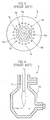
- Fig. 1 is a powder body melting burner according to a preferable embodiment of the present invention and shows a front view of the burner head thereof.
- Fig. 2 is a longitudinal sectional view of the powder body melting burner of Fig. 1.
- Fig. 3 is a front view of a burner head in a powder body melting burner of the conventional art.
- Fig. 4 is a schematic cross-sectional view in the case where the powder body melting burner is used for a melting furnace.
- Next, a powder body melting burner according to the present invention will be described by way of a preferable embodiment with reference to the accompanying drawings. It should be noted that, in this embodiment, assuming heavy oils as the fuel, and moreover, water as the cooling medium used for the burner body and burner head, and moreover, an electric furnace dust, a reducing slag, a burned ash, or the like as the powder body or powder like perticulates. However, the scope of the present invention is not restricted thereto, as a matter of course.
- Furthermore, the term "powder body" to be used in the present invention is not restricted to the so-called pure and simple powder-like powder body, but includes grain-like ones and granular ones, and further even a fluid body composed of the so-called collection of chip-like small pieces. Namely, one example of the powder body to be treated with the powder body melting burner according to the present invention includes an electric furnace dust, a reducing slag, a burned ash, or the like to be a slag after having been melted. Moreover, another example includes a powder-granular waste plastic, a shredder dust, a carbonized sludge, or the like to be gasified by combustion. Furthermore, another example includes a powder-granular iron ore, nickel ore, copper ore, molybdenite ore, or the like which exist as a metal oxide, a metal sulfide or a metal hydroxide, a metal carbonation or the like, and which serves as metal by separating the oxygen, the sulfur, the hydroxyl radical, the carbonic acid radical, or the like, respectively.
- Fig. 1 shows a
burner head 30 viewed from the front of a powderbody melting burner 10 according to the embodiment, and Fig. 2 is a cross-sectional view traveled down through the powderbody melting burner 10 in the axis direction. The powderbody melting burner 10 is cylindrical as a whole, forms a cylinder body with a required length, and is inserted into the furnace body at right angles, thereby causing theburner head 30 to direct to the bottom of the furnace, as described with respect to Fig. 4. - The
burner head 30 has a powderbody injection hole 12 with a required diameter, as a single body, opened at the center thereof, and the powder body is pumped together with air to be inject-supplied into the furnace through a powderbody supply pipe 26 as will be described later. As for the pore size of the powderbody injection hole 12, the dimensions thereof will be set so that the powder body can be supplied most efficiently per a unit of time according to the melting ability of the powder body and the capacity of the furnace body. Moreover, the inner face of the powderbody injection hole 12 is coated with a refractory and wear resistant lamination so as to withstand the wear out due to the sliding friction as the powder body passes. - In the
burner head 30, threefuel injection holes 14 are provided in the radial direction with the central angle of 120 degrees centering on the powderbody injection hole 12, and thisfuel injection hole 14 inject-supplies heavy oils into the furnace under pressure through afuel injection nozzle 40 and afuel supply pipe 36 as will be described later. In this embodiment, although there are provided three fuel injection holes with the equal angle of 120 degrees centering on the powderbody injection hole 12, the arrangement number and the arrangement angle are the design matters, and a suitable arrangement will be employed depending on the actual design. Moreover, the clearance of the individualfuel injection hole 14 relative to the powderbody injection hole 12 is also a pure and simple design matter and a suitable value will be selected in a specific design phase. - Moreover, in the periphery of the
fuel injection hole 14 in theburner head 30, a single primaryoxygen injection hole 16 for inject-supplying the primary oxygen is provided, accordingly. To this primaryoxygen injection hole 16, the primary oxygen is supplied as a combustion assisting gas, under pressure, through aprimary oxygen nozzle 38 and a primaryoxygen supply pipe 28, as will be described later. - Furthermore, a number of holes are opened with a required interval so as to enclose each of the powder
body injection holes 12 and thefuel injection holes 14 in theburner head 30, and these holes configure, as a whole, an annular secondaryoxygen injection hole 18 with respect to each of the powderbody injection holes 12 and thefuel injection holes 14. To this secondaryoxygen injection hole 18, the secondary oxygen is supplied as a combustion assisting gas through a secondaryoxygen supply pipe 32 as will be described later. - In Fig. 2, the powder
body melting burner 10 is based on aburner body 24 that forms a long and hollow cylinder shape, and theburner head 30 forms one end face portion of theburner body 24. Inside the cylinder body of theburner body 24, a secondaryoxygen supply pipe 32 that forms the cylinder body, whose diameter is smaller than that of theburner body 24, is concentrically inserted therein to extend in the axis direction, and one end portion on the burner head side is connected to the secondaryoxygen injection hole 18 as will be described later, and the other end portion is connected to the secondary oxygen pumping source (not shown). - Between the
burner body 24 and the secondaryoxygen supply pipe 32, acylindrical partition wall 34 is insert-supported via aspacer 48 to configure acooling jacket 22, and to this cooling jacket 22 a liquid cooling medium, for example, water is supplied cyclically. - In Fig. 2, a cylindrical secondary
oxygen supply block 46 is embedded in the center of theburner head 30, and the powderbody injection hole 12 is opened at the center of this secondaryoxygen supply block 46. Moreover, in the secondary oxygen supply block 46 a number of secondaryoxygen injection holes 18 are made in the radial direction and in the circumferential direction with a predetermined interval centering on the powderbody injection hole 12, and these secondaryoxygen injection holes 18 form, as a whole, an annular column surrounding the powderbody injection hole 12. The backside of the powderbody injection hole 12 is continuously connected to the powderbody supply pipe 26 that extends in the axis direction inside theburner body 24, and this powderbody supply pipe 26 is connected to the powder body pumping source (not shown). - Because the secondary
oxygen injection holes 18, which have been made as the circular column in large numbers in the secondaryoxygen supply block 46, are in communication with the secondaryoxygen supply pipe 32 inside theburner body 24, the secondary oxygen is supplied from these secondaryoxygen injection holes 18, in the form of enclosing the powder body to be supplied from the powderbody injection hole 12. - In the
burner head 30, each of the threefuel injection holes 14 provided with the central angle of 120 degrees centering on the powderbody injection hole 12 is made on the top of thefuel injection nozzle 40 shown in Fig. 2. Moreover, in theburner head 30, the top of the hollow cylindricalprimary oxygen nozzle 38 faces to the periphery which is concentric with thefuel injection nozzle 40. Namely, as shown in Fig. 2, inside the secondaryoxygen supply pipe 32, three primaryoxygen supply pipes 28 extend to the axis direction, respectively, with the central angle of 120 degrees centering on the powderbody supply pipe 26. - In this primary
oxygen supply pipe 28, the front end thereof is connected to theprimary oxygen nozzle 38 and supplies the primary oxygen as the assisting gas from the periphery of thefuel injection nozzle 40, and the other end is connected to the primary oxygen pumping source (not shown). Furthermore, inside the primaryoxygen supply pipe 28 thefuel supply pipe 36 is inserted coaxially to extend, and the front end thereof is connected to thefuel injection nozzle 40, and the back end is connected to the fuel (heavy oils) pumping source (not shown). - Moreover, as shown in Fig. 1, in the burner head 30 a number of secondary oxygen injection holes 18 are made to enclose each of the three fuel injection holes 14 and the primary
oxygen injection hole 16, thereby forming a circular column as a whole. Because these secondary oxygen injection holes 18 are opened in the secondaryoxygen supply pipe 32 on the back side of theburner head 30 as shown in Fig. 2, the secondary oxygen is injected also from these secondary oxygen injection holes to further enclose the heavy oils injected from thefuel injection hole 14 and the primary oxygen injected from the firstoxygen injection hole 16. - As shown in Fig. 2, on the back side of the
burner head 30 and in the region in which a plurality of the fuel injection holes 14 are provided, apartition plate 42 is provided to define acooling chamber 20 therein. In the center of thispartition plate 42, acirculation hole 44 for the cooling water is opened, and the cooling water from the coolingjacket 22 is supplied cyclically to the coolingchamber 20 through thecirculation hole 44, and accordingly there is an advantage that not only the external cylinder region of theburner 10 but also aplane portion 31 of theburner head 30 can be cooled actively. - Namely, in the periphery of the powder
body injection hole 12, thefuel injection hole 14, the primaryoxygen injection hole 16, and the secondaryoxygen injection hole 18 in theburner head 30, the air and oxygen that flow at high speed through these holes become the cooling medium (air cooling), thereby carrying out a suitable cooling: However, because the effect by the air cooling may not reach theplane portion 31 region in theburner head 30, the region being apart from these holes, it becomes at extremely high temperatures unless being cooled by water, and invites an increase of the thermal expansion or thermal stress, thereby resulting in burnout of the burner in many cases, with this region being as the starting point. Accordingly, cooling theplane portion 31 of theburner head 30 actively by means of water circulation as described above can improve the life of the burner remarkably while preventing the burnout of the burner. - According to the powder
body melting burner 10 of the embodiment, the powder body is injected from the powderbody injection hole 12 to be opened at the center of theburner head 30, and heavy oils are inject-supplied from the three fuel injection holes 14 positioned outward in the radial direction centering on the powderbody injection hole 12 of theburner head 30, respectively. Moreover, from the primaryoxygen injection hole 16 provided concentrically with thefuel injection hole 14, the primary oxygen is also inject-supplied. In this case, while a bundle of discharging flow of the three heavy oils encloses the surrounding of the powder body to be injected from the powderbody injection hole 12, the secondary oxygen injected from the secondaryoxygen injection hole 18 encloses the surrounding of the powder body and the surrounding of the heavy oils. - For this reason, when igniting the heavy oils, the powder body will be in the form of being confined in the central part of high temperature flames which are combustion-supported by the primary oxygen and the secondary oxygen, and it is therefore possible to significantly reduce the carry-over phenomenon that the powder body concerned is spewed out from the flames to the outside. Moreover, because the back side of the
burner head 30 is cooled with a liquid that passes through the coolingchamber 20, not only the external cylinder portion of the burner but also theplane portion 31 of theburner head 30 will be cooled consequently, and therefore the durable life of the powderbody melting burner 10 can be extended. - One example of the powder body to be treated with the powder body melting burner according to the present invention includes an electric furnace dust, a reducing slag, a burned ash, or the like to be a slag after having been melted. Moreover, another example includes a powder-granular waste plastic, shredder dust, carbonized sludge, or the like to be gasified by combustion. Furthermore, another example includes a powder-granular iron ore, nickel ore, copper ore, molybdenite stone, or the like which exists as a metal oxide, a metal sulfide, a metal hydroxide, a metal carbonation or the like, and which serves as metal by separating the oxygen, sulfur, hydroxyl radical, carbonic acid radical, or the like. Namely, the powder body to be melting-treated suitably with the powder body melting burner according to the present invention includes a metal oxide, a metal sulfide, a metal hydroxide, a metal carbonation, and the complex body thereof.
- Furthermore, the furnace body, in which the powder body melting burner of the present invention is used suitably, includes a melting treatment furnace in which, for example, powder particles or the like made by crushing an electric furnace dust, a reducing slag, a burned ash or other plastic waste are melted in high temperature flames, which is recovered as a molten slag in the furnace. Moreover, another furnace body includes a melting reduction furnace in which, for example, a granular metal oxide, metal sulfide or the like are melted in high temperature flames and at the same time the oxygen, sulfur, or the like are separated and recovered as a molten metal in the furnace.
- While supplying the powder body from the center of the burner head, the fuel is supplied from a plurality of places in the outside of the powder body, and thereby the powder body immediately after having been inject-supplied into the furnace is in the state that the surrounding thereof is enclosed with the fuel. Therefore, the powder body is prevented from escaping from flames, and thus the operation loss can be reduced.
- Moreover, because the fuel is not inject-supplied into the furnace from one place of the burner head, but is inject-supplied from a plurality of places and burned, the length of each of the flames becomes short by necessity, and accordingly, the height of the furnace body also can be designed to be short, thereby allowing the manufacturing cost to be suppressed. Furthermore, in the case where the furnace of the same height is used, because the length of flames becomes short, the flames will not reach the peripheral furnace wall, and thus, there is an advantage that the wear out of the refractory materials of the furnace-wall can be alleviated.
Claims (4)
- A powder body melting burner (10) which injects a powder body, fuel, and oxygen into a furnace individually from a burner head (30) and melts the powder body in flames in which the fuel is burned under oxygen support, the powder body melting burner (10) comprising:a single powder body injection hole (12) provided in the center of the burner head (30);a plurality of fuel injection holes (14) disposed with a required central angle in the radial direction centering on the powder body injection hole (12);a single primary oxygen injection hole (16) provided concentrically with each of the fuel injection holes (14); anda plurality of secondary oxygen injection holes (18) arranged in large numbers with a predetermined interval so as to enclose each of the powder body injection holes (12) and the fuel injection holes (14), the plurality of secondary oxygen injection holes (18) forming a ring shape as a whole.
- The powder body melting burner according to claim 1, wherein a plurality of the fuel injection holes (14) are provided with a central angle of about 120 degrees in the radial direction centering on the powder body injection hole (12).
- The powder body melting burner according to claim 1 or 2, wherein a cooling chamber (20) is provided in the back side of the burner head (30) and in the region in which the plurality of fuel injection holes (14) are provided, and a coolant from a cooling jacket (22) arranged in the periphery of a burner body (24) is supplied cyclically to this cooling chamber (20), thereby cooling a plane section (31) of the burner head (30).
- The powder body melting burner according to any one of claims 1 to 3, wherein the powder body to be melted with the powder body melting burner includes a metal oxide, a metal sulfide, a metal hydroxide, a metal carbonate, and a complex thereof.
Applications Claiming Priority (1)
| Application Number | Priority Date | Filing Date | Title |
|---|---|---|---|
| JP2004341058A JP4288503B2 (en) | 2004-11-25 | 2004-11-25 | Powder melting burner |
Publications (2)
| Publication Number | Publication Date |
|---|---|
| EP1669669A1 true EP1669669A1 (en) | 2006-06-14 |
| EP1669669B1 EP1669669B1 (en) | 2008-09-17 |
Family
ID=35500812
Family Applications (1)
| Application Number | Title | Priority Date | Filing Date |
|---|---|---|---|
| EP05025556A Expired - Lifetime EP1669669B1 (en) | 2004-11-25 | 2005-11-23 | High temperature oxy-fuel burner with powder injection system |
Country Status (8)
| Country | Link |
|---|---|
| US (1) | US7402275B2 (en) |
| EP (1) | EP1669669B1 (en) |
| JP (1) | JP4288503B2 (en) |
| CN (1) | CN100582575C (en) |
| AU (1) | AU2005237134A1 (en) |
| BR (1) | BRPI0505423A (en) |
| CA (1) | CA2527398A1 (en) |
| DE (1) | DE602005009788D1 (en) |
Cited By (3)
| Publication number | Priority date | Publication date | Assignee | Title |
|---|---|---|---|---|
| EP2405197A1 (en) | 2010-07-05 | 2012-01-11 | L'air Liquide, Societe Anonyme Pour L'etude Et L'exploitation Des Procedes Georges Claude | Low maintenance combustion method suitable for use in a glass forehearth |
| WO2012110434A3 (en) * | 2011-02-14 | 2013-09-26 | L'air Liquide Societe Anonyme Pour L'etude Et L'exploitation Des Procedes Georges Claude | Burner for uniformly heating a long furnace |
| CN113757660A (en) * | 2021-09-29 | 2021-12-07 | 广东美的白色家电技术创新中心有限公司 | Burners and gas stoves |
Families Citing this family (13)
| Publication number | Priority date | Publication date | Assignee | Title |
|---|---|---|---|---|
| JP4606138B2 (en) * | 2004-11-30 | 2011-01-05 | 花王株式会社 | Inorganic spheroidizing particle production equipment |
| TWI381897B (en) * | 2004-12-22 | 2013-01-11 | 大陽日酸股份有限公司 | Method for manufacturing metal ultrafine powder |
| FR2947737B1 (en) * | 2009-07-08 | 2012-05-25 | Fives Stein | DEVICE FOR SEPARATING ATMOSPHERES |
| JP2013245880A (en) * | 2012-05-25 | 2013-12-09 | Daido Ecomet Co Ltd | Powder and granular material melting burner and powder and granular material melting device |
| CN102767827B (en) * | 2012-07-27 | 2015-04-08 | 上海锅炉厂有限公司 | Combined-type thermal-oxidation igniting process nozzle for gasifying solid powder fuel |
| JP5925730B2 (en) * | 2013-05-31 | 2016-05-25 | 新日鉄住金マテリアルズ株式会社 | Spherical particle production burner |
| US9677758B2 (en) | 2013-09-06 | 2017-06-13 | Honeywell International Inc. | Gaseous fuel-oxygen burner |
| DE102015105144A1 (en) * | 2015-04-02 | 2016-10-06 | Gefam Gmbh | Flämmkopf |
| JP6695213B2 (en) * | 2016-05-19 | 2020-05-20 | 日本製鉄株式会社 | Burner and Burner Cooling Method |
| CN108443874B (en) * | 2018-05-21 | 2024-03-22 | 温岭市博惠热能设备股份有限公司 | Combustor and combustion head thereof |
| JP7029432B2 (en) * | 2019-09-26 | 2022-03-03 | 大陽日酸株式会社 | Burner for producing inorganic spheroidized particles, inorganic spheroidized particle production equipment, and method for producing inorganic spheroidized particles |
| CN112169695A (en) * | 2020-08-17 | 2021-01-05 | 凌岩 | Device and method for reducing wall attachment in high-temperature spheroidization of silicon dioxide microspheres |
| CN116136305A (en) * | 2021-11-17 | 2023-05-19 | 新奥(天津)能源技术有限公司 | Fly ash melting method and fly ash melting system |
Citations (7)
| Publication number | Priority date | Publication date | Assignee | Title |
|---|---|---|---|---|
| US5042964A (en) * | 1988-05-26 | 1991-08-27 | American Combustion, Inc. | Flash smelting furnace |
| US5968230A (en) * | 1994-12-08 | 1999-10-19 | Daido Tokushuko Kabushiki Kaisha | Method and furnace for disposal of steel-making waste, and operating method of the furnace |
| JP2000103656A (en) | 1999-08-30 | 2000-04-11 | Daido Steel Co Ltd | Burner for steelmaking waste treatment |
| EP1092785A1 (en) * | 1999-10-12 | 2001-04-18 | Praxair Technology, Inc. | Coherent jet lancing system for gas and powder delivery |
| US20030075843A1 (en) * | 2001-08-29 | 2003-04-24 | Empco (Canada) Ltd. | Multi-purpose, multi-oxy-fuel, power burner/injector/oxygen lance device |
| US6558614B1 (en) * | 1998-08-28 | 2003-05-06 | Voest-Alpine Industrieanlagenbau Gmbh | Method for producing a metal melt and corresponding multifunction lance |
| EP1462717A2 (en) * | 2003-03-24 | 2004-09-29 | Shin-Etsu Chemical Co., Ltd. | Burner for the manufacture of synthetic quartz glass |
Family Cites Families (6)
| Publication number | Priority date | Publication date | Assignee | Title |
|---|---|---|---|---|
| US75843A (en) * | 1868-03-24 | Improvement in seeding-attachment to hoes | ||
| US2920001A (en) * | 1955-07-11 | 1960-01-05 | Union Carbide Corp | Jet flame spraying method and apparatus |
| US5966230A (en) * | 1990-05-29 | 1999-10-12 | Symbol Technologies, Inc. | Integrated scanner on a common substrate |
| JP3968760B2 (en) * | 1997-03-05 | 2007-08-29 | 大同特殊鋼株式会社 | Powder melting burner |
| JP4038876B2 (en) * | 1998-05-20 | 2008-01-30 | 大同特殊鋼株式会社 | Powder melting burner |
| JP4550989B2 (en) * | 2000-11-01 | 2010-09-22 | 大同特殊鋼株式会社 | Powder melting burner |
-
2004
- 2004-11-25 JP JP2004341058A patent/JP4288503B2/en not_active Expired - Lifetime
-
2005
- 2005-11-21 CA CA002527398A patent/CA2527398A1/en not_active Abandoned
- 2005-11-22 BR BRPI0505423-0A patent/BRPI0505423A/en not_active IP Right Cessation
- 2005-11-23 DE DE602005009788T patent/DE602005009788D1/en not_active Expired - Lifetime
- 2005-11-23 EP EP05025556A patent/EP1669669B1/en not_active Expired - Lifetime
- 2005-11-23 US US11/286,675 patent/US7402275B2/en not_active Expired - Lifetime
- 2005-11-24 AU AU2005237134A patent/AU2005237134A1/en not_active Abandoned
- 2005-11-25 CN CN200510125558A patent/CN100582575C/en not_active Expired - Fee Related
Patent Citations (7)
| Publication number | Priority date | Publication date | Assignee | Title |
|---|---|---|---|---|
| US5042964A (en) * | 1988-05-26 | 1991-08-27 | American Combustion, Inc. | Flash smelting furnace |
| US5968230A (en) * | 1994-12-08 | 1999-10-19 | Daido Tokushuko Kabushiki Kaisha | Method and furnace for disposal of steel-making waste, and operating method of the furnace |
| US6558614B1 (en) * | 1998-08-28 | 2003-05-06 | Voest-Alpine Industrieanlagenbau Gmbh | Method for producing a metal melt and corresponding multifunction lance |
| JP2000103656A (en) | 1999-08-30 | 2000-04-11 | Daido Steel Co Ltd | Burner for steelmaking waste treatment |
| EP1092785A1 (en) * | 1999-10-12 | 2001-04-18 | Praxair Technology, Inc. | Coherent jet lancing system for gas and powder delivery |
| US20030075843A1 (en) * | 2001-08-29 | 2003-04-24 | Empco (Canada) Ltd. | Multi-purpose, multi-oxy-fuel, power burner/injector/oxygen lance device |
| EP1462717A2 (en) * | 2003-03-24 | 2004-09-29 | Shin-Etsu Chemical Co., Ltd. | Burner for the manufacture of synthetic quartz glass |
Cited By (5)
| Publication number | Priority date | Publication date | Assignee | Title |
|---|---|---|---|---|
| EP2405197A1 (en) | 2010-07-05 | 2012-01-11 | L'air Liquide, Societe Anonyme Pour L'etude Et L'exploitation Des Procedes Georges Claude | Low maintenance combustion method suitable for use in a glass forehearth |
| WO2012110434A3 (en) * | 2011-02-14 | 2013-09-26 | L'air Liquide Societe Anonyme Pour L'etude Et L'exploitation Des Procedes Georges Claude | Burner for uniformly heating a long furnace |
| US9416965B2 (en) | 2011-02-14 | 2016-08-16 | L'Air Liquide Société Anonyme Pour L'Étude Et L'Exploitation Des Procedes Georges Claude | Burner for uniformly heating a long furnace |
| CN113757660A (en) * | 2021-09-29 | 2021-12-07 | 广东美的白色家电技术创新中心有限公司 | Burners and gas stoves |
| CN113757660B (en) * | 2021-09-29 | 2023-08-29 | 广东美的白色家电技术创新中心有限公司 | Burner and gas stove |
Also Published As
| Publication number | Publication date |
|---|---|
| US20060108724A1 (en) | 2006-05-25 |
| US7402275B2 (en) | 2008-07-22 |
| CN1782494A (en) | 2006-06-07 |
| CN100582575C (en) | 2010-01-20 |
| EP1669669B1 (en) | 2008-09-17 |
| JP2006153305A (en) | 2006-06-15 |
| JP4288503B2 (en) | 2009-07-01 |
| AU2005237134A1 (en) | 2006-06-08 |
| CA2527398A1 (en) | 2006-05-25 |
| DE602005009788D1 (en) | 2008-10-30 |
| BRPI0505423A (en) | 2006-07-11 |
Similar Documents
| Publication | Publication Date | Title |
|---|---|---|
| EP1669669B1 (en) | High temperature oxy-fuel burner with powder injection system | |
| ES2587849T3 (en) | Refrigerated fluid lances for superior submerged injection | |
| KR100767876B1 (en) | Apparatus for Injecting Gas into a Vessel | |
| JP5087955B2 (en) | Melting reduction method | |
| KR20110052545A (en) | Method and apparatus for igniting and operating burners in gasification of carbon containing fuel | |
| AU663040B2 (en) | Melting furnace with gas injection | |
| NO166671B (en) | OBSERVING FLAMES AND BURNS. | |
| US8945464B2 (en) | Heating method and system for controlling air ingress into enclosed spaces | |
| JP2023543051A (en) | Blast furnace with shaft supply of hot process gas | |
| CN107326142B (en) | A kind of converter bottom blown protective brick and its masonry method and smelting method | |
| US5397109A (en) | Reduced emissions metal melting furnace | |
| JP5113075B2 (en) | In-furnace material detection system for metal production lances | |
| JP3261574B2 (en) | Non-consumable water cooling lance | |
| EP1767856A1 (en) | Tuyere structure of waste fusion furnace and combustible dust blowing method | |
| JP3838616B2 (en) | Radioactive waste incineration melting processing apparatus and incineration melting processing method | |
| WO2011024814A1 (en) | Gas jet device | |
| JP3941526B2 (en) | Waste powder melting method and melting equipment used therefor | |
| US705418A (en) | Burner for the removal of hardened masses in furnaces or the like. | |
| KR100559798B1 (en) | Brown gas multi-burner for melting incineration ash | |
| JP2013245880A (en) | Powder and granular material melting burner and powder and granular material melting device | |
| JP2875870B2 (en) | Oxygen / fuel burner for flash smelting ore concentrate burner | |
| JP2006010199A (en) | Melting treatment method of waste | |
| KR100771662B1 (en) | Smelting apparatus | |
| CA1111244A (en) | Hot cupola gas burner | |
| JP2025527631A (en) | Gas injector for shaft injection in blast furnaces |
Legal Events
| Date | Code | Title | Description |
|---|---|---|---|
| PUAI | Public reference made under article 153(3) epc to a published international application that has entered the european phase |
Free format text: ORIGINAL CODE: 0009012 |
|
| AK | Designated contracting states |
Kind code of ref document: A1 Designated state(s): AT BE BG CH CY CZ DE DK EE ES FI FR GB GR HU IE IS IT LI LT LU LV MC NL PL PT RO SE SI SK TR |
|
| AX | Request for extension of the european patent |
Extension state: AL BA HR MK YU |
|
| 17P | Request for examination filed |
Effective date: 20061103 |
|
| AKX | Designation fees paid |
Designated state(s): DE FR IT |
|
| GRAP | Despatch of communication of intention to grant a patent |
Free format text: ORIGINAL CODE: EPIDOSNIGR1 |
|
| GRAS | Grant fee paid |
Free format text: ORIGINAL CODE: EPIDOSNIGR3 |
|
| GRAA | (expected) grant |
Free format text: ORIGINAL CODE: 0009210 |
|
| RAP1 | Party data changed (applicant data changed or rights of an application transferred) |
Owner name: DAIDO ECOMET KABUSHIKI KAISHA Owner name: DAIDO TOKUSHUKO KABUSHIKI KAISHA |
|
| AK | Designated contracting states |
Kind code of ref document: B1 Designated state(s): DE FR IT |
|
| REF | Corresponds to: |
Ref document number: 602005009788 Country of ref document: DE Date of ref document: 20081030 Kind code of ref document: P |
|
| PLBE | No opposition filed within time limit |
Free format text: ORIGINAL CODE: 0009261 |
|
| STAA | Information on the status of an ep patent application or granted ep patent |
Free format text: STATUS: NO OPPOSITION FILED WITHIN TIME LIMIT |
|
| 26N | No opposition filed |
Effective date: 20090618 |
|
| PGFP | Annual fee paid to national office [announced via postgrant information from national office to epo] |
Ref country code: DE Payment date: 20091119 Year of fee payment: 5 |
|
| PGFP | Annual fee paid to national office [announced via postgrant information from national office to epo] |
Ref country code: FR Payment date: 20091123 Year of fee payment: 5 Ref country code: IT Payment date: 20091117 Year of fee payment: 5 |
|
| REG | Reference to a national code |
Ref country code: FR Ref legal event code: ST Effective date: 20110801 |
|
| REG | Reference to a national code |
Ref country code: DE Ref legal event code: R119 Ref document number: 602005009788 Country of ref document: DE Effective date: 20110601 Ref country code: DE Ref legal event code: R119 Ref document number: 602005009788 Country of ref document: DE Effective date: 20110531 |
|
| PG25 | Lapsed in a contracting state [announced via postgrant information from national office to epo] |
Ref country code: FR Free format text: LAPSE BECAUSE OF NON-PAYMENT OF DUE FEES Effective date: 20101130 |
|
| PG25 | Lapsed in a contracting state [announced via postgrant information from national office to epo] |
Ref country code: IT Free format text: LAPSE BECAUSE OF NON-PAYMENT OF DUE FEES Effective date: 20101123 |
|
| PG25 | Lapsed in a contracting state [announced via postgrant information from national office to epo] |
Ref country code: DE Free format text: LAPSE BECAUSE OF NON-PAYMENT OF DUE FEES Effective date: 20110531 |