EP1669666A1 - Backlight device and liquid crystal display - Google Patents
Backlight device and liquid crystal display Download PDFInfo
- Publication number
- EP1669666A1 EP1669666A1 EP04788076A EP04788076A EP1669666A1 EP 1669666 A1 EP1669666 A1 EP 1669666A1 EP 04788076 A EP04788076 A EP 04788076A EP 04788076 A EP04788076 A EP 04788076A EP 1669666 A1 EP1669666 A1 EP 1669666A1
- Authority
- EP
- European Patent Office
- Prior art keywords
- light
- primary color
- color light
- optical unit
- emitting
- Prior art date
- Legal status (The legal status is an assumption and is not a legal conclusion. Google has not performed a legal analysis and makes no representation as to the accuracy of the status listed.)
- Withdrawn
Links
Images







Classifications
-
- G—PHYSICS
- G02—OPTICS
- G02F—OPTICAL DEVICES OR ARRANGEMENTS FOR THE CONTROL OF LIGHT BY MODIFICATION OF THE OPTICAL PROPERTIES OF THE MEDIA OF THE ELEMENTS INVOLVED THEREIN; NON-LINEAR OPTICS; FREQUENCY-CHANGING OF LIGHT; OPTICAL LOGIC ELEMENTS; OPTICAL ANALOGUE/DIGITAL CONVERTERS
- G02F1/00—Devices or arrangements for the control of the intensity, colour, phase, polarisation or direction of light arriving from an independent light source, e.g. switching, gating or modulating; Non-linear optics
- G02F1/01—Devices or arrangements for the control of the intensity, colour, phase, polarisation or direction of light arriving from an independent light source, e.g. switching, gating or modulating; Non-linear optics for the control of the intensity, phase, polarisation or colour
- G02F1/13—Devices or arrangements for the control of the intensity, colour, phase, polarisation or direction of light arriving from an independent light source, e.g. switching, gating or modulating; Non-linear optics for the control of the intensity, phase, polarisation or colour based on liquid crystals, e.g. single liquid crystal display cells
- G02F1/133—Constructional arrangements; Operation of liquid crystal cells; Circuit arrangements
- G02F1/1333—Constructional arrangements; Manufacturing methods
- G02F1/1335—Structural association of cells with optical devices, e.g. polarisers or reflectors
-
- G—PHYSICS
- G02—OPTICS
- G02B—OPTICAL ELEMENTS, SYSTEMS OR APPARATUS
- G02B6/00—Light guides; Structural details of arrangements comprising light guides and other optical elements, e.g. couplings
- G02B6/0001—Light guides; Structural details of arrangements comprising light guides and other optical elements, e.g. couplings specially adapted for lighting devices or systems
- G02B6/0011—Light guides; Structural details of arrangements comprising light guides and other optical elements, e.g. couplings specially adapted for lighting devices or systems the light guides being planar or of plate-like form
- G02B6/0013—Means for improving the coupling-in of light from the light source into the light guide
- G02B6/0015—Means for improving the coupling-in of light from the light source into the light guide provided on the surface of the light guide or in the bulk of it
- G02B6/0018—Redirecting means on the surface of the light guide
-
- G—PHYSICS
- G02—OPTICS
- G02B—OPTICAL ELEMENTS, SYSTEMS OR APPARATUS
- G02B6/00—Light guides; Structural details of arrangements comprising light guides and other optical elements, e.g. couplings
- G02B6/0001—Light guides; Structural details of arrangements comprising light guides and other optical elements, e.g. couplings specially adapted for lighting devices or systems
-
- G—PHYSICS
- G02—OPTICS
- G02B—OPTICAL ELEMENTS, SYSTEMS OR APPARATUS
- G02B6/00—Light guides; Structural details of arrangements comprising light guides and other optical elements, e.g. couplings
- G02B6/0001—Light guides; Structural details of arrangements comprising light guides and other optical elements, e.g. couplings specially adapted for lighting devices or systems
- G02B6/0011—Light guides; Structural details of arrangements comprising light guides and other optical elements, e.g. couplings specially adapted for lighting devices or systems the light guides being planar or of plate-like form
- G02B6/0033—Means for improving the coupling-out of light from the light guide
- G02B6/005—Means for improving the coupling-out of light from the light guide provided by one optical element, or plurality thereof, placed on the light output side of the light guide
- G02B6/0055—Reflecting element, sheet or layer
-
- G—PHYSICS
- G02—OPTICS
- G02B—OPTICAL ELEMENTS, SYSTEMS OR APPARATUS
- G02B6/00—Light guides; Structural details of arrangements comprising light guides and other optical elements, e.g. couplings
- G02B6/0001—Light guides; Structural details of arrangements comprising light guides and other optical elements, e.g. couplings specially adapted for lighting devices or systems
- G02B6/0011—Light guides; Structural details of arrangements comprising light guides and other optical elements, e.g. couplings specially adapted for lighting devices or systems the light guides being planar or of plate-like form
- G02B6/0033—Means for improving the coupling-out of light from the light guide
- G02B6/0056—Means for improving the coupling-out of light from the light guide for producing polarisation effects, e.g. by a surface with polarizing properties or by an additional polarizing elements
-
- G—PHYSICS
- G02—OPTICS
- G02B—OPTICAL ELEMENTS, SYSTEMS OR APPARATUS
- G02B6/00—Light guides; Structural details of arrangements comprising light guides and other optical elements, e.g. couplings
- G02B6/0001—Light guides; Structural details of arrangements comprising light guides and other optical elements, e.g. couplings specially adapted for lighting devices or systems
- G02B6/0011—Light guides; Structural details of arrangements comprising light guides and other optical elements, e.g. couplings specially adapted for lighting devices or systems the light guides being planar or of plate-like form
- G02B6/0066—Light guides; Structural details of arrangements comprising light guides and other optical elements, e.g. couplings specially adapted for lighting devices or systems the light guides being planar or of plate-like form characterised by the light source being coupled to the light guide
- G02B6/0068—Arrangements of plural sources, e.g. multi-colour light sources
-
- G—PHYSICS
- G02—OPTICS
- G02F—OPTICAL DEVICES OR ARRANGEMENTS FOR THE CONTROL OF LIGHT BY MODIFICATION OF THE OPTICAL PROPERTIES OF THE MEDIA OF THE ELEMENTS INVOLVED THEREIN; NON-LINEAR OPTICS; FREQUENCY-CHANGING OF LIGHT; OPTICAL LOGIC ELEMENTS; OPTICAL ANALOGUE/DIGITAL CONVERTERS
- G02F1/00—Devices or arrangements for the control of the intensity, colour, phase, polarisation or direction of light arriving from an independent light source, e.g. switching, gating or modulating; Non-linear optics
- G02F1/01—Devices or arrangements for the control of the intensity, colour, phase, polarisation or direction of light arriving from an independent light source, e.g. switching, gating or modulating; Non-linear optics for the control of the intensity, phase, polarisation or colour
- G02F1/13—Devices or arrangements for the control of the intensity, colour, phase, polarisation or direction of light arriving from an independent light source, e.g. switching, gating or modulating; Non-linear optics for the control of the intensity, phase, polarisation or colour based on liquid crystals, e.g. single liquid crystal display cells
- G02F1/133—Constructional arrangements; Operation of liquid crystal cells; Circuit arrangements
- G02F1/1333—Constructional arrangements; Manufacturing methods
- G02F1/1335—Structural association of cells with optical devices, e.g. polarisers or reflectors
- G02F1/1336—Illuminating devices
- G02F1/133602—Direct backlight
- G02F1/133603—Direct backlight with LEDs
Definitions
- the present invention relates to a backlight apparatus for surface emission, having an LED device or the like as its light source, and a liquid crystal display using the backlight apparatus, and more particularly, to a backlight apparatus and a liquid crystal display which are capable of achieving high color reproductivity.
- the light guiding path 12A and the reflection path 12B are designed to have a space necessary for naturally mixing the light emitted from the LED devices 11B, 11G and 11R to become the white light Lw.
- a width W and a diameter R in Fig. 2 are set to predetermined dimensions enough for forming such space.
- materials of the light guiding path 12A and the reflection path 12B are predetermined materials so that the light is reflected with a suitable refraction index for performing light guiding or reflection efficiently.
- Patent Document 1 Utility Model Publication No. 7-36347, JP-T 2002540458
- a liquid crystal display apparatus described in claim 7 has a backlight apparatus having at least an optical unit which includes a light source (W) for emitting white light (W), a first mirror surface body for transmitting a first polarized wave (P) and reflecting a second polarized wave (S), a second mirror surface body for reflecting the second polarized wave (S) reflected by the first mirror surface body, and a polarization converting device ( ⁇ /2 phase difference plate) for converting the second polarized wave (S) reflected by the second mirror surface body into the first polarized wave (P) ; wherein a polarized wave to be emitted is emitted aligned with the first polarized wave (P) ; and a liquid crystal display panel for displaying an image by using light surface-emitted from the backlight apparatus.
- W light source
- P first mirror surface body
- S second mirror surface body for reflecting the second polarized wave (S) reflected by the first mirror surface body
- a polarization converting device ⁇ /2 phase difference plate
- the reflecting mirror 172 reflects the S-component reflected by the polarizedbeam splitter 171 and emits it toward the ⁇ /2 phase difference plate 173.
- the cost of the backlight apparatus 151 can be reduced by the cost of it and also the thickness of the backlight apparatus 151 can be reduced.
- the blue light Lb, the green light Lg and the red light Lr emitted from the LED device 11 by the optical unit 61 are forcibly mixed and formed the white light Lw, and the optical unit 162 reuses the S-component light which has not been in use, so that color purity and light utilization rate can be improved in the backlight apparatus having an LED device as its light source.
Landscapes
- Physics & Mathematics (AREA)
- General Physics & Mathematics (AREA)
- Optics & Photonics (AREA)
- Nonlinear Science (AREA)
- Mathematical Physics (AREA)
- Chemical & Material Sciences (AREA)
- Crystallography & Structural Chemistry (AREA)
- Planar Illumination Modules (AREA)
- Liquid Crystal (AREA)
Abstract
Description
- The present invention relates to a backlight apparatus for surface emission, having an LED device or the like as its light source, and a liquid crystal display using the backlight apparatus, and more particularly, to a backlight apparatus and a liquid crystal display which are capable of achieving high color reproductivity.
- Fig. 1 shows a configuration example of a liquid crystal display for displaying images, which constitutes a computer terminal, a mobile electronic device or a television receiver.
- A
liquid crystal displaypanel 2 is constituted by sealing liquid crystals between two polarizing plates (not shown), and displays images by changing directions of liquid crystal molecules by applying voltage to vary light transmissivity. Since the liquid crystals themselves of the liquidcrystal display panel 2 do not emit light, abacklight apparatus 1 performs surface emission from the back side of the liquidcrystal display panel 2. - This
backlight apparatus 1 is configured withLED devices light guiding plate 12, adiffusion sheet 13, aBEF sheet 14 and a D-BEF sheet 15, which are stacked one after the other as shown in the figure and disposed so as to oppose the liquidcrystal display panel 2, and performs surface emission toward the liquidcrystal display panel 2. - As the light sources of the surface emission, the
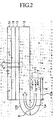
LED devices backlight apparatus 1 emit blue light Lb, green light Lg, red light Lr, respectively. As shown in Fig. 2, the blue light Lb, the green light Lg and the red light Lr emitted from the LED device 11 are naturally mixed and becomes white light Lw while being led by thelight guiding plate 12. - In the example of Fig. 1, there is provided only one for each of the
LED devices respective LED devices - As shown in Fig. 2, the
light guiding plate 12 guides the light entered through alight guide path 12A and areflection path 12B to thediffusion sheet 13 disposed on the top surface of thelight guiding plate 12. - The light guiding
path 12A and thereflection path 12B are designed to have a space necessary for naturally mixing the light emitted from theLED devices path 12A and thereflection path 12B are predetermined materials so that the light is reflected with a suitable refraction index for performing light guiding or reflection efficiently. - The
light guiding plate 12 has a bottom portion on which, for example, dots are formed in order to exit light to each portion of thediffusion sheet 13 as uniformly as possible, so that some of the guided light is reflected by the dots and exited to thediffusion sheet 13 side. - The
diffusion sheet 13 is made of, for example, a polycarbonate film of 0.25mm in thickness, uniforms the light entered from thelight guiding plate 12 by diffusing ununiformed part thereof, and transmits the resultant light to theBEF sheet 14. - A BEF (Brightness Enhancement Firm) sheet (brightness improvement sheet for P-component: the BEF series is a product name of Sumitomo 3M company) 14 converges the P-component beyond a viewing angle of the liquid crystal of the liquid crystal display panel 2 (a visible angle for a user, of the light transmitted through the liquid crystal display panel 2) among the P-component of the light entered through the
diffusion sheet 13 to within the viewing angle. Since the light (P-component) beyond the viewing angle of the liquidcrystal display panel 2, which is invisible for a user even passed through the liquidcrystal display panel 2, is to be converged within the viewing angle in this manner, apparent brightness can be improved. It is to be noted that, an S-component of the light entered to the BEF sheet is transmitted to the D-BEF sheet 15 as it is. - The D-BEF sheet (brightness improvement sheet for S-component) 15 converts the S-component of the light entered through the
BEF sheet 14 into the P-component and, as similar to theBEF sheet 14, converges the P-component light beyond the viewing angle of the liquidcrystal display panel 2, and transmits the converged light to the liquidcrystal display panel 2. - The liquid crystal displaypanel 2 (Fig. 1) is originally configured to transmit only the P-component by the polarizing plate. In response to a signal from a not shown signal line, the liquid
crystal display panel 2 controls directions of the liquid crystals by each pixel unit and varies the transmission amount of the white light Lw which is formed by the light generated from the LED device 11 and entered via thelight guiding plate 12, thediffusion sheet 13, theBEF sheet 14 and the D-BEF sheet 15 to form and display images. - It is to be noted that, in addition to the example of Fig. 1, an example of a backlight apparatus having an LED device as a light source which naturally mixes blue light, red light and green light emitted from the LED device is disclosed in Utility Model Publication No. Hei 7-36347 and JP-T 2002540458.
- [Patent Document 1] Utility Model Publication No. 7-36347, JP-T 2002540458
- However, as shown in Fig. 1, when the light from the LED device 11 is naturally mixed, there entered, for example, BR (magenta), RG (yellow), BG (cyan), and further, a mixed color light of them in the obtained light other than the primary color light of the blue light Lb, the red light Lr, and the green light, so that there is a problem of occurring color irregularities. It is to be noted that primary color filters of a blue (B), a red (R) and a green (G) are disposed on the liquid
crystal display panel 2. - The present invention is made in view of such circumstances, and to improve high color reproductivity, for example, in the backlight apparatus having an LED device as its light source, without color irregularities.
- [0017]
- A back light apparatus described in
claim 1 is an apparatus that uses a relay dichroic mirror for color mixing of BGRprimary color. The present invention has at least an optical unit including a first light source (B) for emitting a first primary color light (for example, B, hereinafter it is referred to in a similar manner), a second light source (G) for emitting a second primary color light (for example, G), a third light source (R) for emitting a third primary color light (for example, R), a first mirror surface body for reflecting the first primary color light (B) and/or transmitting other primary color light, a second mirror surface body for reflecting the second primary color light (G) and/or transmitting other primary color light, a third mirror surface body for reflecting the third primary color light (R) and/or transmitting other primary color light; and color mixing means that mixes each of the color light transmitted through the first, second and thirdmirror surface bodies and emits white light. - A back light apparatus described in
claim 2 is an apparatus that uses a cross dichroic mirror for color mixing of BGRprimary color. The backlight apparatus of the present invention has at least an optical unit including a first light source (B) for emitting a first primary color light (B), (a mirror surface body for reflecting the first primary color light (B)), a second light source (G) for emitting a second primary color light (G); a third light source (R) for emitting a third primary color light(R), (a mirror surface body reflecting the third primary color (R)), and a cross dichroic device having a first dichroic film for reflecting the first primary color light (B) and transmitting the second primary color light (G) and a second dichroic film for reflecting the third primary color light (R) and transmitting the second primary color light (G), in an X-shape, for emitting white light by mixing the first, second and third primary color light. It is to be noted that (a mirror surface body for reflecting the first primary color light (B)) and (a mirror surface body reflecting the third primary color (R)) are omitted from claim because they are not essential elements. - A back light apparatus described in claim 3 is an apparatus that adopts a polarization conversion system for an optical unit to align a polarization direction of emission. The backlight apparatus has at least an optical unit including a light source (W) for emitting white light (W), a first mirror surface body for transmitting a first polarized wave (P) and reflecting a secondpolarized wave (S), a second mirror surface body for transmitting the second polarized wave (S) reflected by the first mirror surface body, and a polarization converting device (λ/2 phase difference plate) for converting the second polarized wave (S) reflected by the second mirror surface body into the first polarized wave (P) ; wherein a polarized wave to be emitted is emitted aligned with the first polarized wave (P) .
- A back light apparatus described in claim 4 is an apparatus for carrying out a polarization conversion after the color mixture. That is, in the backlight apparatus described in claim 3, the light source (W) is white light obtained by mixing each of primary color light emitted from a first light source (B) for emitting a first primary color light (B), a second light source (G) for emitting a second primary color light (G) , and a third light source (R) for emitting a third primary color light(R).
- It is to be noted that the color mixture of BGR primary color of the present invention and the polarization conversion can be arbitrarily combined. Namely, the case where after the polarization conversion is carried out for each BGR primarily color by the technique in claim 3, the color mixture is carried out by the techniques in
claim 1 andclaim 2 is also included in the idea of the present invention. - A liquid crystal display apparatus described in claim 5 has a backlight apparatus having at least an optical unit which includes a first light source (B) for emitting a first primary color light (B), a second light source (G) for emitting a second primary color light (G), a third light source (R) for emitting a third primary color light(R), a first mirror surface body for reflecting the first primary color light (B) and/or transmitting other primary color light, a second mirror surface body for reflecting the second primary color light (G) and/or transmitting other primary color light, a third mirror surface body for reflecting the third primary color light (R)and/or transmitting other primary color light; and color mixing means that mixes each of the color light transmitted through the first, second, third mirror surface bodies and emits white light; and a liquid crystal display panel for displaying an image by using light surface-emitted from the backlight apparatus.
- A liquid crystal display apparatus described in claim 6 has a backlight apparatus having at least an optical unit which includes a first light source (B) for emitting a first primary color light (B), a second light source (G) for emitting a second primary color light (G), a third light source (R) for emitting a third primary color light (R), and a cross dichroic device having a first dichroic film for reflecting the first primary color light (B) and transmitting the second primary color light (G) and a second dichroic film for reflecting the third primary color light (R) and transmitting the second primary color light (G), in an X-shape, for emitting white light by mixing the first, second and third primary color light; and a liquid crystal display panel for displaying an image by using light surface-emitted from the backlight apparatus.
- A liquid crystal display apparatus described in claim 7 has a backlight apparatus having at least an optical unit which includes a light source (W) for emitting white light (W), a first mirror surface body for transmitting a first polarized wave (P) and reflecting a second polarized wave (S), a second mirror surface body for reflecting the second polarized wave (S) reflected by the first mirror surface body, and a polarization converting device (λ/2 phase difference plate) for converting the second polarized wave (S) reflected by the second mirror surface body into the first polarized wave (P) ; wherein a polarized wave to be emitted is emitted aligned with the first polarized wave (P) ; and a liquid crystal display panel for displaying an image by using light surface-emitted from the backlight apparatus.
- According to the present invention, in the backlight apparatus having a light emitting diode device as its light source, the blue light Lb, the green light Lg and the red light Lr emitted from the light emitting diode device are mixed by the dichroic mirror, so that only pure light of Lb, Lr and Lg are optically mixed without color irregularities. Therefore, the white light Lw having high color purity and high color reproductively can be surface-emitted to the liquid
crystal display panel 2. Specifically, the present invention is effective to a backlight apparatus for a television receiver and the like, which is required to have high image quality. -
- Fig. 1 is a perspective view showing a configuration of a conventional backlight apparatus;
- Fig. 2 is a cross-sectional view of a light guiding plate of Fig. 1;
- Fig. 3 is a perspective view showing a configuration of a backlight apparatus to which the present invention is applied;
- Fig. 4 is a view showing a configuration example of an optical unit of Fig. 3;
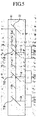
- Fig. 5 is another view showing the configuration example of the optical unit of Fig. 3;
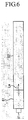
- Fig. 6 is a view showing a joining relation between a LED device, the optical unit and a light guiding plate of Fig. 3;
- Fig. 7 is a view showing another joining relation between the LED device, the optical unit and the light guiding plate of Fig. 3;
- Fig. 8 is a view showing another joining relation between the LED device, the optical unit and the light guiding plate of Fig. 3;
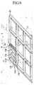
- Fig. 9 is a view showing another configuration example of the optical unit of Fig. 3;
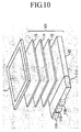
- Fig. 10 is a perspective view of a configuration of another backlight apparatuses to which the present invention is applied;
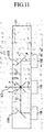
- Fig. 11 is a cross-sectional view of an optical unit of Fig. 10;
- Fig. 12 is a perspective view of a configuration of another backlight apparatuses to which the present invention is applied;
- Fig. 13 is a view showing a configuration example of an optical unit of Fig. 12;
- Fig. 14 is a view showing another configuration example of the optical unit of Fig. 12;
- Fig. 15 is a perspective view showing a configuration of another backlight apparatuses to which the present invention is applied;
- Fig. 16 is a view showing a configuration example of an optical unit of Fig. 15;
- Fig. 17 is a view showing another configuration example of the optical unit of Fig. 15;
- Fig. 18 is a perspective view of another configuration of a backlight apparatus to which the present invention is applied;
- Fig. 19 is a view showing a configuration example of an optical unit of Fig. 18; and
- Fig. 20 is a view showing another configuration example of the optical unit of Fig. 18.
- In the following, embodiments of the present invention are described, however this description is intended to confirm the invention defined in the present specification. Accordingly, even if there exists an embodiment which is not described in the embodiments, this does not mean that such embodiment does not correspond to the present invention. To the contrary, even if it is described as an embodiment below, this does not mean that the embodiment does not correspond to any invention other than the invention.
- Hereinafter, embodiments of the present invention will be explained referring to accompanying drawings.
- Fig. 3 shows a configuration example of a
backlight apparatus 51 to which the present invention is applied. The present embodiment is an example in which a relay dichroic mirror system is adopted for color mixing of BGR primary color light. In thebacklight apparatus 51, anoptical unit 61 and alight guiding plate 62 are provided in place of thelight guiding path 12A and thereflection path 12B in thebacklight apparatus 51 of Fig. 1. Because other portions are similar to the case in Fig. 1, explanations for these are duly omitted. - As a backlight apparatus, as shown in Fig. 1 and Fig. 3,there are an edge light type in which an LED device or a CCFL (Cold Cathode Fluorescent Lamp) is disposed at the side surface of a light guiding plate and a direct type (it is also called as an area light type or a backlight type) in which a plurality of lamps and an LED light source are disposed immediately under a liquid crystal display panel. The edge light type is explained here as an example, however, as described later, the present invention can also be applied to the direct type in the similar way.
-
LED devices light guiding plate 62 are joined to anoptical unit 61. - In the inside of the
optical unit 61, as shown in a perspective view of theoptical unit 61 in Fig. 4 and in a cross sectional view of theoptical unit 61 viewed from the above in Fig. 5, there are disposed adichroic mirror 71B which transmits green light Lg and red light Lr and reflects blue light Lb, adichroic mirror 71G which transmits the blue light Lb and the red light Lr and reflects the green light Lg, and adichroic mirror 71R which transmits the blue light Lb and the green light Lg and reflects the red light Lr, and they transmit or reflect the light emitted from theLED devices mirror 72 for performing total reflection is disposed so that the white light Lw formed by thedichroic mirrors light guiding plate 62. - In other words, the blue light (Lb) emitted from the
LED device 11B is reflected by thedichroic mirror 71B toward thedichroic mirror 71G. - The light (Lb + Lg), in which the blue light Lb which is reflected by the
dichroic mirror 71B and transmitted through thedichroic mirror 71G and the green light Lg which is emitted from theLED device 11G and reflected by thedichroic mirror 71G are mixed, is emitted toward thedichroic mirror 71R. - (Lb + Lg + Lr), in which the mixed light of blue and green which is emitted from the
diachronic mirror 71G and transmitted through thedichroic mirror 71R and the red light (Lr) which is emitted from theLED device 11R and reflected by thedichroic mirror 71R are mixed, is emitted toward the total reflection mirror 72 (that is, the white light Lw is emitted toward the total reflection mirror 72). - From the
total reflection mirror 72, the mixed light of blue, green and red (Lb + Lg + Lr = Lw: white light) emitted from thedichroic mirror 71R is emitted toward thelight guiding plate 62. - The
light guiding plate 62 guides the white light Lw emitted from theoptical unit 61 and leads the light effectively uniformed by a predetermined structure (for example, a structure for uniforming an emitted light by forming dots on the bottom portion thereof to reflect some of the guided light by the dots) to thediffusion sheet 13 effectively. - As described above, unlike in the conventional case of natural mixing, the blue light Lb, the green light Lg and the red light Lr are forcibly mixed by the dichroic mirror 71 so that only pure blue light Lb, pure green light Lg and pure red light Lr are optically mixed. Therefore, the backlight apparatus having an LED device as its light source can surface-emits the white light Lw capable of reproducing high color (so-called higher color purity) to the liquid
crystal display panel 2 while suppressing occurring color irregularities. - It is to be noted that, in the example in Fig. 3, there is provided only one for each of the
LED devices LED devices - In addition, in the example of Fig. 3, the LED device 11, the
optical unit 61 and thelight guiding plate 62 are arranged and joined in a horizontal direction as shown in Fig. 6, however, they can be joined as shown in Fig. 7 or Fig. 8. In the case where theoptical unit 61 is disposed an under surface of thelight guiding plate 62 as shown in Fig. 7, the LED device 11 and the dichroic mirror 71 (not shown) of theoptical unit 61 are disposed in a back direction in the sheet of Fig. 7, and thetotal reflection mirror 72 is disposed in thelight guiding plate 62 so that the mixed light (white light Lw) is to be led to thelight guiding plate 62. - In the case of the example in Fig. 8, the
optical unit 61 is disposed on under side of thelight guiding plate 62. That is, this is an example of applying to the aforementioned direct type backlight apparatus. In this case, theLED devices optical unit 61. The dichroic mirror 71 (not shown) is disposed in the inside of theoptical unit 61 so that the white light Lw mixed by the dichroic mirror 71 is entered directly to thelight guiding plate 62. - Further, in addition to the arrangement in which the
LED devices optical unit 61, as shown in Fig. 9, they can be arranged such that chiptype LED devices dichroic mirror total reflection mirror 72 are arranged in a plane to form a direct type plane LED backlight apparatus. - Fig. 10 shows a configuration example of a
backlight apparatus 101 to which the present invention is applied. The present embodiment is an example in which a cross dichroic mirror system is adopted for color mixing of BGR primary color light. In thebacklight apparatus 101, anoptical unit 111 is provided in place of theoptical unit 61 of thebacklight apparatus 51 of Fig. 3. Because other portions are similar to the case of Fig. 3, explanations for these are duly omitted. - Similar to the
optical unit 61,LED devices light guiding plate 62 are joined to anoptical unit 111. In the inside of theoptical unit 111, as shown in a cross-sectional view of theoptical unit 111 viewed from the above in Fig. 11, adichroic mirror 121R, adichroic mirror 121B and a crossdichroic mirror 122 are disposed corresponding to theLED devices - The
dichroic mirror 121R reflects the red light Lr and transmits other colors, and thedichroic mirror 121B reflects the blue light Lb and transmits other colors. The crossdichroic mirror 122 has a structure in which a mirror (a) which reflects the red light Lr and transmits other colors and a mirror (b) which reflects the blue light Lb and transmits other colors are crossed each other. - The red light Lr emitted from the
LED device 11R is reflected by thedichroic mirror 121R and moves toward the crossdichroic mirror 122 direction. The blue light Lb emitted from theLED device 11B is reflected by thedichroic mirror 121B and moves toward the crossdichroic mirror 122 direction. The green light Lg emitted from theLED device 11G is emitted directly toward the crossdichroic mirror 122 direction. - The red light Lr entered from the
dichroic mirror 121R and the blue light Lb entered from thedichroic mirror 121B are reflected by the crossdichroic mirror 122 and exit to a surface where they exit. The green light Lg emitted from theLED device 11G passes through the crossdichroic mirror 122 and exits to the surface. - Therefore, from the optical unit 111 (cross dichroic mirror 122), white light (Lb + Lg + Lr = Lw) which is forcibly mixed of the blue light Lb, the green light Lg and the red light Lr is emitted toward the
light guiding plate 62. - The
light guiding plate 62 guides the white light Lw entered from theoptical unit 111 and leads the light, which is effectively uniformed by a predetermined structure, to adiffusion sheet 13 effectively. - As described above, because the blue light Lb, the green light Lg and the red light Lr are forcibly mixed by using the
dichroic mirror dichroic mirror 122, theoptical unit 111 can be made small in size (the number of mirrors is reduced by one) in comparison with theoptical unit 61 using thetotal reflection mirror 72 shown in Fig. 3. In addition, similar to theoptical unit 61, because only the pure blue light Lb, the pure red light Lr and the pure green light Lg are optically mixed, color irregularities can be suppressed from occurring. - Fig. 12 shows a configuration example of a
backlight apparatus 151 to which the present invention is applied. The present embodiment adopts a polarization conversion system for an optical unit, which aligns a polarization direction of emission. In thebacklight apparatus 151, anLED device 161 and anoptical unit 162 are provided in place of the LED device 11 and theoptical unit 61 of thebacklight apparatus 51 in Fig. 3. In addition, the D-BEF sheet 15 of thebacklight apparatus 51 of Fig. 3 is omitted. - The
LED device 161 emitting white light Lw and thelight guiding plate 62 are joined to theoptical unit 162. In the inside of theoptical unit 162, as shown in a cross-sectional view of theoptical unit 162 viewed from the above in Fig. 13, apolarized beam splitter 171, a reflectingmirror 172 and a λ/2phase difference plate 173 are disposed corresponding to theLED device 161. - The polarized beam splitter 171 (Polarized Beam Splitter: PBS) converges and transmits P-component light of the white light Lw emitted from the
LED device 161, and emits it toward thelight guiding plate 62 while reflecting S-component light toward the reflectingmirror 172. It is to be noted that thepolarized beam splitter 171 polarized-splits the white light Lw into two linear polarizations (P-polarization and S-polarization) so as to have equal strengths and orthogonal polarized directions, respectively. - The reflecting
mirror 172 reflects the S-component reflected by thepolarizedbeam splitter 171 and emits it toward the λ/2phase difference plate 173. - The λ/2
phase difference plate 173 converts the S-components light emitted from the reflectingmirror 172 into the P-component light, and emits it toward thelight guiding plate 62. - Accordingly, from the
optical unit 162, the P-component light of the white light Lw emitted by theLED device 161 and the P-component light which is converted from the S-component light by the λ/2 phase difference plate 172 (two P-component light rays) are emitted toward thelight guiding plate 62. - As described above, because the P-component light of the white light Lw emitted by the
LED device 161 and the P-component light which is converted from the S-component of the white light Lw (a plurality of light rays from one light source) are emitted toward thelight guiding plate 62, a light utilization rate of a backlight in the back light apparatus having an LED device as its light source can be improved, as compared to the case where one white light ray LW is emitted to thelight guiding plate 62. In other words, of the P+ S-components emitted from the white light Lw, the S-component which is originally not in use is converted into the P-components and reused, whereby the light utilization rate of the backlight can be increased double. - In addition, because only the P-component light is entered to the
light guiding plate 62, the D-BEF sheet which is used for converting the S-component into the P-component as described before is not necessary, the cost of thebacklight apparatus 151 can be reduced by the cost of it and also the thickness of thebacklight apparatus 151 can be reduced. - It is to be noted that, in the example of the backlight apparatus shown in Fig. 12, each one of the
LED device 161, thepolarized beam splitter 171, the reflectingmirror 172 and the λ/2phase difference plate 173 are respectively provided for simplicity, however they can be multiply provided in a predetermined ratio. - In this case, the backlight apparatus may be configured by arranging the structure shown in Fig. 13 in the order, or may be configured by disposing the
LED device 161, thepolarizing beam splitter 171, the reflectingmirror 172 and the λ/2phase difference board 173 symmetrically, as shown in Fig. 14. In an example of Fig. 14, two pair of thepolarized beam splitter 171, the reflectingmirror 172 and the λ/2phase difference plate 173 are symmetrically disposed. As a result of providing them in a symmetric structure as above, theoptical unit 162 can be made more compact and light equalization in thebacklight apparatus 151 can be achieved. - Fig. 15 shows a configuration example of a
backlight apparatus 201 to which the present invention is applied. The present embodiment is an example in which a polarization conversion is carried out after the color mixture of the BGR primary color light. In thebacklight apparatus 201, the optical unit 61 (Fig. 3) which forcibly mixes the light from theLED devices LED device 161 of thebacklight apparatus 151 of Fig. 12. - In this case, as shown in Fig. 16,the
polarized beam splitter 171 of theoptical unit 162 converges and transmits the P-component of the white light (Lb + Lg + Lr = Lw) from the optical unit 61which is obtained by forcibly mixing the blue light Lb, the green light Lg and the red light Lr emitted from theLED device light guiding plate 62 while reflecting the S-component of the light toward the reflectingmirror 172. - The reflecting
mirror 172 reflects the S-component reflected by thepolarized beam splitter 171, and emits it toward the λ/2phase difference plate 173. The λ/2phase difference plate 173 converts the S-component light emitted from the reflectingmirror 172 into the P-component light, and emits it toward thelight guiding plate 62. - Accordingly, in this example, from the
optical unit 162, the P-component light of the white light Lw obtained by forcibly mixing theLED device optical unit 61 and the P-component light which is converted from the S-component light are emitted toward thelight guiding plate 62. - As described above, the blue light Lb, the green light Lg and the red light Lr emitted from the LED device 11 by the
optical unit 61 are forcibly mixed and formed the white light Lw, and theoptical unit 162 reuses the S-component light which has not been in use, so that color purity and light utilization rate can be improved in the backlight apparatus having an LED device as its light source. - It is to be noted that, in Fig. 15, the
optical unit 61 which forcibly mixes the light with the dichroic mirror 71 and thetotal reflection mirror 72 is used, however, in place of it, as shown in Fig. 17, theoptical unit 111 which forcibly mixes the light with the crossdichroic mirror 122 shown in Fig. 10 can also be used. - Fig. 18 shows a configuration example of a
backlight apparatus 251 to which the present invention is applied. The present embodiment is an example in which the color mixture of the BGR primary color light is carried out after the polarization conversion. In thebacklight apparatus 251, optical units (units for converting the S-component into the P-component) 162R, 162G and 162B are provided corresponding to theLED devices backlight apparatus 51 of Fig. 3. - In other words, in this example, from the
optical unit 61, as shown in Fig. 19, the P-component of the blue light Lb emitted fromoptical unit 162B and the P-component converted from the S-component of the blue light Lb, the P-component of the green light Lg emitted from theoptical unit 162G and the P-component converted from the S-component of the green light Lg, and the P-component of the red light Lr emitted from theoptical unit 162R and the P-component coveted from the S-components of the red light Lr are forcibly mixed, respectively, by theoptical unit 61, and it is emitted toward thelight guiding plate 62. - As described above, the S-component light which has not been in use is converted into the P-component light by the
optical unit 162 to use, and the P-component blue light Lb, the P-component green light Lg and the P-component red light Lr are forcibly mixed by theoptical unit 61, whereby color purity can be improved in the backlight apparatus having an LED device as its light source. - It is to be noted that, in Fig. 19, the
optical unit 61 which forcibly mixes the light with the dichroic mirror 71 and thetotal reflection mirror 72, in place of it, as shown in Fig. 20, theoptical unit 111 which forcibly mixes the light with the crossdichroic mirror 122 shown in Fig. 10 can be used.
Claims (7)
- A backlight apparatus having at least an optical unit, the optical unit comprising:a first light source for emitting a first primary color light;a second light source for emitting a secondprimary color light;a third light source for emitting a third primary color light;a first mirror surface body for reflecting the first primary color light and/or transmitting other primary color light;a second mirror surface body for reflecting the second primary color light and/or transmitting other primary color light;a third mirror surface body for reflecting the third primary color light and/or transmitting other primary color light; andcolor mixing means that mixes each of the color light transmitted through the first, second and third mirror surface bodies and emits white light.
- A backlight apparatus having at least an optical unit, the optical unit comprising:a first light source for emitting a first primary color light;a second light source for emitting a second primary color light;a third light source for emitting a third primary color light; anda cross dichroic device having a first dichroic film for reflecting the first primary color light and transmitting the second primary color light and a second dichroic film for reflecting the third primary color light and transmitting the second primary color light, in an X-shape, for emitting white light by mixing the first, second and third primary color light.
- A backlight apparatus having at least an optical unit, the optical unit, comprising:a light source for emitting white light;a first mirror surface body for transmitting a first polarized wave and reflecting a second polarized wave;a second mirror surface body for transmitting the second polarized wave reflected by the first mirror surface body; anda polarization converting device for converting the second polarized wave reflected by the second mirror surface body into the first polarized wave;wherein a polarized wave to be emitted is emitted aligned with the first polarized wave.
- The backlight apparatus according to claim 3, characterized in that:the light source is white light obtained by mixing each of primary color light emitted from a first light source for emitting a first primary color light, a second light source for emitting a second primary color light, and a third light source for emitting a third primary color light.
- A liquid crystal display apparatus, characterized by comprising:a backlight apparatus having at least an optical unit,the optical unit having
a first light source for emitting a first primary color light,
a second light source for emitting a secondprimary color light,
a third light source for emitting a third primary color light,
a first mirror surface body for reflecting the first primary color light and/or transmitting other primary color light,
a second mirror surface body for reflecting the second primary color light and/or transmitting other primary color light;
a third mirror surface body for reflecting the third primary color light and/or transmitting other primary color light, and
color mixing means that mixes each of the color light transmitted through the first, second, third mirror surface bodies and emits white light; anda liquid crystal display panel for displaying an image by using light surface-emitted from the backlight apparatus. - A liquid crystal display apparatus, characterized by comprising:a backlight apparatus having at least an optical unit,the optical unit having
a first light source for emitting a first primary color light,
a second light source for emitting a second primary color light,
a third light source for emitting a third primary color light, and
a cross dichroic device having a first dichroic film for reflecting the first primary color light and transmitting the second primary color light and a second dichroic film for reflecting the third primary color light and transmitting the second primary color light, in an X-shape, for emitting white light by mixing the first, second and third primary color light; anda liquid crystal display panel for displaying an image by using light surface-emitted from the backlight apparatus. - A liquid crystal display apparatus, characterized by comprising:a backlight apparatus having at least an optical unit,the optical unit having
a light source for emitting white light,
a first mirror surface body for transmitting a first polarized wave and reflecting a second polarized wave,
a second mirror surface body for reflecting the second polarized wave reflected by the first mirror surface body, and
a polarization converting device for converting the second polarized wave reflected by the second mirror surface body into the first polarized wave,
wherein a polarized wave to be emitted is emitted aligned with the first polarized wave; anda liquid crystal display panel for displaying an image by using light surface-emitted from the backlight apparatus.
Applications Claiming Priority (2)
| Application Number | Priority Date | Filing Date | Title |
|---|---|---|---|
| JP2003340810A JP2005107181A (en) | 2003-09-30 | 2003-09-30 | Backlight device, liquid crystal display device |
| PCT/JP2004/013917 WO2005033579A1 (en) | 2003-09-30 | 2004-09-24 | Backlight device and liquid crystal display |
Publications (2)
| Publication Number | Publication Date |
|---|---|
| EP1669666A1 true EP1669666A1 (en) | 2006-06-14 |
| EP1669666A4 EP1669666A4 (en) | 2008-01-23 |
Family
ID=34419192
Family Applications (1)
| Application Number | Title | Priority Date | Filing Date |
|---|---|---|---|
| EP04788076A Withdrawn EP1669666A4 (en) | 2003-09-30 | 2004-09-24 | LIGHT DEVICE AND LIQUID CRYSTAL DISPLAY |
Country Status (7)
| Country | Link |
|---|---|
| US (2) | US7413331B2 (en) |
| EP (1) | EP1669666A4 (en) |
| JP (1) | JP2005107181A (en) |
| KR (1) | KR20060066048A (en) |
| CN (1) | CN1705847A (en) |
| TW (1) | TWI262340B (en) |
| WO (1) | WO2005033579A1 (en) |
Cited By (1)
| Publication number | Priority date | Publication date | Assignee | Title |
|---|---|---|---|---|
| WO2008007254A3 (en) * | 2006-06-22 | 2008-06-19 | Koninkl Philips Electronics Nv | Symmetrical light guide structure for led based ambilight |
Families Citing this family (36)
| Publication number | Priority date | Publication date | Assignee | Title |
|---|---|---|---|---|
| KR100691191B1 (en) * | 2005-07-15 | 2007-03-09 | 삼성전기주식회사 | Surface light source using LED and LCD backlight unit having same |
| KR100751455B1 (en) * | 2005-09-16 | 2007-08-23 | 삼성전자주식회사 | LCD Display |
| JP4622787B2 (en) * | 2005-09-30 | 2011-02-02 | 日立ライティング株式会社 | Backlight system and liquid crystal display device |
| CN100464233C (en) * | 2006-01-17 | 2009-02-25 | 群康科技(深圳)有限公司 | Backlight module |
| US7553061B2 (en) | 2006-07-23 | 2009-06-30 | Chunghwa Picture Tubes, Ltd. | Side type backlight module |
| KR101340437B1 (en) | 2006-09-25 | 2013-12-11 | 삼성디스플레이 주식회사 | Back cover used in display device, back light assembly and display device having the same |
| TWI335477B (en) * | 2006-10-16 | 2011-01-01 | Chimei Innolux Corp | Backlight unit and liquid crystal display device using the same |
| TWI361919B (en) * | 2006-10-27 | 2012-04-11 | Ind Tech Res Inst | Driving method of liquid crystal display panel |
| WO2008065763A1 (en) * | 2006-11-30 | 2008-06-05 | Sharp Kabushiki Kaisha | Support structure and support member for discharge tube, discharge tube, base, illuminating device, display, and tv receiver |
| TWI384439B (en) * | 2007-08-16 | 2013-02-01 | Richtek Technology Corp | Multi-color backlight control circuit and method |
| US7379130B1 (en) | 2007-10-03 | 2008-05-27 | Vitera Llc | LCD with hetero polar light guide |
| JP5211732B2 (en) | 2008-02-14 | 2013-06-12 | ソニー株式会社 | Lighting period setting method, display panel driving method, lighting condition setting device, semiconductor device, display panel, and electronic apparatus |
| US7766536B2 (en) * | 2008-02-15 | 2010-08-03 | Lunera Lighting, Inc. | LED light fixture |
| DE102008020996A1 (en) * | 2008-04-25 | 2009-11-26 | Lanz, Rüdiger | Motor driven head-movable headlight for producing multiple light and projection effects for using, particularly during event and stage technology, has multiple dichroitic prisms arranged one after other |
| US20100085762A1 (en) * | 2008-10-03 | 2010-04-08 | Peifer Donald A | Optimized spatial power distribution for solid state light fixtures |
| US20100110658A1 (en) * | 2008-10-08 | 2010-05-06 | Peifer Donald A | Semi-direct solid state lighting fixture and distribution |
| US8243426B2 (en) | 2008-12-31 | 2012-08-14 | Apple Inc. | Reducing optical effects in a display |
| KR101693655B1 (en) | 2009-11-12 | 2017-01-06 | 엘지전자 주식회사 | Back Light Unit And Liquid Crystal Display Device Comprising Thereof |
| USRE46781E1 (en) | 2009-11-12 | 2018-04-10 | Lg Electronics Inc. | Backlight unit and liquid crystal display including the same |
| US20120293725A1 (en) * | 2010-01-07 | 2012-11-22 | Sharp Kabushiki Kaisha | Lighting device, display device and television receiver |
| US20110175902A1 (en) * | 2010-01-20 | 2011-07-21 | Apple Inc. | Multilayer display device |
| KR20110103074A (en) | 2010-03-12 | 2011-09-20 | 엘지전자 주식회사 | Display device |
| CN102330950A (en) * | 2010-07-14 | 2012-01-25 | 江苏慧光电子科技有限公司 | Optical system |
| CN102454915B (en) * | 2010-10-14 | 2014-10-15 | 京东方科技集团股份有限公司 | Backlight module and liquid crystal display (LCD) |
| KR101262634B1 (en) * | 2011-03-14 | 2013-05-08 | 엘지이노텍 주식회사 | Display device |
| US8960963B1 (en) * | 2011-09-26 | 2015-02-24 | The Boeing Company | Dual wavelength focusable and steerable searchlight |
| US9176536B2 (en) | 2011-09-30 | 2015-11-03 | Apple, Inc. | Wireless display for electronic devices |
| KR20130053061A (en) * | 2011-11-14 | 2013-05-23 | 엘지디스플레이 주식회사 | Light guiding plate, backlight unit and liquid crystal display device using the sames |
| KR102110121B1 (en) | 2012-04-26 | 2020-05-13 | 휴렛 팩커드 엔터프라이즈 디벨롭먼트 엘피 | Optical slab |
| US9810942B2 (en) | 2012-06-15 | 2017-11-07 | Apple Inc. | Quantum dot-enhanced display having dichroic filter |
| CN104832885A (en) * | 2015-04-24 | 2015-08-12 | 深圳市华星光电技术有限公司 | Liquid crystal display, backlight module and light guide plate for backlight module |
| CN106569298A (en) * | 2015-10-08 | 2017-04-19 | 小米科技有限责任公司 | Light guide plate structure, display assembly and electronic equipment |
| CN105467504B (en) * | 2015-12-31 | 2018-11-30 | 京东方科技集团股份有限公司 | Down straight aphototropism mode set and display device |
| KR102321892B1 (en) * | 2017-04-11 | 2021-11-05 | 삼성디스플레이 주식회사 | Display apparatus and method of manufacturing the same |
| CN113419370B (en) * | 2018-06-06 | 2022-10-18 | 上海中航光电子有限公司 | Liquid crystal display device having a plurality of pixel electrodes |
| CN112444908A (en) * | 2019-08-29 | 2021-03-05 | 京东方科技集团股份有限公司 | Light guide structure, preparation method thereof, light source and display device |
Family Cites Families (24)
| Publication number | Priority date | Publication date | Assignee | Title |
|---|---|---|---|---|
| JPH05241103A (en) | 1992-02-21 | 1993-09-21 | Nec Corp | Projection type liquid crystal display device |
| US5748828A (en) * | 1993-11-10 | 1998-05-05 | Alliedsignal Inc. | Color separating backlight |
| KR0164463B1 (en) | 1994-11-25 | 1999-03-20 | 이헌조 | Optical device of liquid crystal project |
| JP2915317B2 (en) * | 1995-02-28 | 1999-07-05 | インターナショナル・ビジネス・マシーンズ・コーポレイション | Light guide unit, liquid crystal display device and polarization method |
| NO300188B1 (en) | 1995-03-15 | 1997-04-21 | Mul T Lock Ltd | Chamber and magazine lock for weapons |
| SE506992C2 (en) | 1995-11-02 | 1998-03-09 | Bjoern Magnusson | Firearms locking device |
| KR100189062B1 (en) * | 1995-12-11 | 1999-06-01 | 이해규 | Liquid crystal projector using one color lcd |
| JPH10321005A (en) * | 1997-05-16 | 1998-12-04 | Canon Inc | Illumination device and projection device using the same |
| EP0922990B1 (en) * | 1997-12-11 | 2008-07-23 | Hunet Display Technology Inc. | Color display device |
| US6412207B1 (en) | 1998-06-24 | 2002-07-02 | Caleb Clark Crye | Firearm safety and control system |
| KR100450542B1 (en) * | 1998-10-29 | 2004-10-01 | 가부시키가이샤 히타치세이사쿠쇼 | Illuminating apparatus and liquid crystal display using the same |
| TW459142B (en) | 1999-12-29 | 2001-10-11 | Lee Chih Kung | Light beam polarization converter for converting an illumination source into a polarization light source |
| JP2001237088A (en) | 2000-02-24 | 2001-08-31 | Asahi National Lighting Co Ltd | Variable color lighting system |
| TW468059B (en) | 2000-10-05 | 2001-12-11 | Chih-Kung Lee | Light beam polarization converter |
| JP4049267B2 (en) * | 2001-06-01 | 2008-02-20 | フィリップス ルミレッズ ライティング カンパニー リミテッド ライアビリティ カンパニー | Compact lighting system and display device |
| JP2003007114A (en) | 2001-06-26 | 2003-01-10 | Sharp Corp | Front light and reflective display device using the same |
| US6948840B2 (en) * | 2001-11-16 | 2005-09-27 | Everbrite, Llc | Light emitting diode light bar |
| JP2003187623A (en) * | 2001-12-18 | 2003-07-04 | Sharp Corp | Illumination device and display device using the same |
| JP3923867B2 (en) * | 2002-07-26 | 2007-06-06 | 株式会社アドバンスト・ディスプレイ | Planar light source device and liquid crystal display device using the same |
| US7320531B2 (en) * | 2003-03-28 | 2008-01-22 | Philips Lumileds Lighting Company, Llc | Multi-colored LED array with improved brightness profile and color uniformity |
| US7222450B2 (en) | 2004-10-18 | 2007-05-29 | N-Trance Security Ltd. | Firearm security block and firearm fitted therewith |
| DE202006010962U1 (en) | 2006-07-15 | 2006-11-09 | Stierhof, Detlev | Blocking system for semi-automatic weapon has metal block inserted in magazine shaft and fixed to barrel lock |
| US7568302B1 (en) | 2008-04-04 | 2009-08-04 | Caracal International L.L.C. | Handgun and locking means for a handgun |
| DE202008017092U1 (en) | 2008-12-24 | 2009-03-19 | Stierhof, Detlev, Dipl.-Hdl. Dipl. STA | Lock system for semi-automatic pistols / self-loading pistols and rifles |
-
2003
- 2003-09-30 JP JP2003340810A patent/JP2005107181A/en active Pending
-
2004
- 2004-09-14 TW TW093127760A patent/TWI262340B/en not_active IP Right Cessation
- 2004-09-24 WO PCT/JP2004/013917 patent/WO2005033579A1/en not_active Ceased
- 2004-09-24 KR KR1020057009614A patent/KR20060066048A/en not_active Withdrawn
- 2004-09-24 EP EP04788076A patent/EP1669666A4/en not_active Withdrawn
- 2004-09-24 CN CNA2004800014278A patent/CN1705847A/en active Pending
- 2004-09-24 US US10/536,511 patent/US7413331B2/en not_active Expired - Fee Related
-
2008
- 2008-03-24 US US12/079,010 patent/US7604362B2/en not_active Expired - Fee Related
Cited By (3)
| Publication number | Priority date | Publication date | Assignee | Title |
|---|---|---|---|---|
| WO2008007254A3 (en) * | 2006-06-22 | 2008-06-19 | Koninkl Philips Electronics Nv | Symmetrical light guide structure for led based ambilight |
| US8016473B2 (en) | 2006-06-22 | 2011-09-13 | Koninklijke Philips Electronics N.V. | Symmetrical light guide structure for LED-based lighting device |
| KR101421420B1 (en) * | 2006-06-22 | 2014-07-29 | 코닌클리케 필립스 엔.브이. | Symmetrical light guide structure for led based ambilight |
Also Published As
| Publication number | Publication date |
|---|---|
| EP1669666A4 (en) | 2008-01-23 |
| US20070064445A1 (en) | 2007-03-22 |
| WO2005033579A1 (en) | 2005-04-14 |
| US20080198570A1 (en) | 2008-08-21 |
| CN1705847A (en) | 2005-12-07 |
| US7604362B2 (en) | 2009-10-20 |
| TWI262340B (en) | 2006-09-21 |
| TW200523637A (en) | 2005-07-16 |
| KR20060066048A (en) | 2006-06-15 |
| JP2005107181A (en) | 2005-04-21 |
| US7413331B2 (en) | 2008-08-19 |
Similar Documents
| Publication | Publication Date | Title |
|---|---|---|
| US7604362B2 (en) | Backlight apparatus, liquid crystal display | |
| US8520164B2 (en) | Illumination device, display device, and light guide plate | |
| US5105265A (en) | Projector apparatus having three liquid crystal panels | |
| US8206020B2 (en) | Planar illuminating device and liquid crystal display device using the same | |
| US5097323A (en) | Liquid crystal projector | |
| JP4123189B2 (en) | Backlight device and liquid crystal display device | |
| US8334942B2 (en) | Backlight device and liquid crystal display | |
| JP2008041528A (en) | Backlight device, light source device, lens, electronic equipment, and light guide plate | |
| JP2005332680A (en) | Illumination device and liquid crystal display device | |
| EP1892565A1 (en) | Display device and backlight unit comprising a holographic optical element | |
| KR100834649B1 (en) | LCD device with black and white LCD panel | |
| US8049838B2 (en) | Direct light type backlight unit and color filterless liquid crystal display apparatus employing the same | |
| JP2006236701A (en) | Backlight device and liquid crystal display device | |
| US7133211B2 (en) | Projector with flat light sources | |
| US7810979B2 (en) | Illuminating device with primary color LED and fluorescent light sources, and liquid crystal display device | |
| US20080192205A1 (en) | Projection Display Device | |
| JP2006228576A (en) | Backlight device and liquid crystal display device | |
| JP4760048B2 (en) | Backlight device and liquid crystal display device | |
| JP2004354751A (en) | Liquid crystal display | |
| CN101573557A (en) | Planar lighting device and liquid crystal display device using the same | |
| US20080094539A1 (en) | Liquid crystal display with black/white liquid crystal display panel | |
| JP2006236770A (en) | Backlight device and liquid crystal display device | |
| JP2005243430A (en) | Planar light source device and display device | |
| JP2009009739A (en) | Color liquid crystal display device | |
| JP5130613B2 (en) | Backlight device and liquid crystal display device |
Legal Events
| Date | Code | Title | Description |
|---|---|---|---|
| PUAI | Public reference made under article 153(3) epc to a published international application that has entered the european phase |
Free format text: ORIGINAL CODE: 0009012 |
|
| 17P | Request for examination filed |
Effective date: 20050527 |
|
| AK | Designated contracting states |
Kind code of ref document: A1 Designated state(s): DE FR GB NL |
|
| DAX | Request for extension of the european patent (deleted) | ||
| RBV | Designated contracting states (corrected) |
Designated state(s): DE FR GB NL |
|
| RIC1 | Information provided on ipc code assigned before grant |
Ipc: G02B 6/00 20060101AFI20071210BHEP |
|
| A4 | Supplementary search report drawn up and despatched |
Effective date: 20071227 |
|
| 17Q | First examination report despatched |
Effective date: 20080618 |
|
| DAX | Request for extension of the european patent (deleted) | ||
| RBV | Designated contracting states (corrected) |
Designated state(s): DE FR GB NL |
|
| STAA | Information on the status of an ep patent application or granted ep patent |
Free format text: STATUS: THE APPLICATION IS DEEMED TO BE WITHDRAWN |
|
| 18D | Application deemed to be withdrawn |
Effective date: 20130403 |