EP1669554B1 - Axiallageranordnung für Gasturbinen - Google Patents
Axiallageranordnung für Gasturbinen Download PDFInfo
- Publication number
- EP1669554B1 EP1669554B1 EP05257401A EP05257401A EP1669554B1 EP 1669554 B1 EP1669554 B1 EP 1669554B1 EP 05257401 A EP05257401 A EP 05257401A EP 05257401 A EP05257401 A EP 05257401A EP 1669554 B1 EP1669554 B1 EP 1669554B1
- Authority
- EP
- European Patent Office
- Prior art keywords
- gas turbine
- coupled
- thrust
- turbine engine
- assembly
- Prior art date
- Legal status (The legal status is an assumption and is not a legal conclusion. Google has not performed a legal analysis and makes no representation as to the accuracy of the status listed.)
- Expired - Lifetime
Links
Images

Classifications
-
- F—MECHANICAL ENGINEERING; LIGHTING; HEATING; WEAPONS; BLASTING
- F01—MACHINES OR ENGINES IN GENERAL; ENGINE PLANTS IN GENERAL; STEAM ENGINES
- F01D—NON-POSITIVE DISPLACEMENT MACHINES OR ENGINES, e.g. STEAM TURBINES
- F01D25/00—Component parts, details, or accessories, not provided for in, or of interest apart from, other groups
- F01D25/16—Arrangement of bearings; Supporting or mounting bearings in casings
- F01D25/166—Sliding contact bearing
- F01D25/168—Sliding contact bearing for axial load mainly
-
- F—MECHANICAL ENGINEERING; LIGHTING; HEATING; WEAPONS; BLASTING
- F01—MACHINES OR ENGINES IN GENERAL; ENGINE PLANTS IN GENERAL; STEAM ENGINES
- F01D—NON-POSITIVE DISPLACEMENT MACHINES OR ENGINES, e.g. STEAM TURBINES
- F01D25/00—Component parts, details, or accessories, not provided for in, or of interest apart from, other groups
- F01D25/16—Arrangement of bearings; Supporting or mounting bearings in casings
- F01D25/162—Bearing supports
- F01D25/164—Flexible supports; Vibration damping means associated with the bearing
-
- F—MECHANICAL ENGINEERING; LIGHTING; HEATING; WEAPONS; BLASTING
- F01—MACHINES OR ENGINES IN GENERAL; ENGINE PLANTS IN GENERAL; STEAM ENGINES
- F01D—NON-POSITIVE DISPLACEMENT MACHINES OR ENGINES, e.g. STEAM TURBINES
- F01D25/00—Component parts, details, or accessories, not provided for in, or of interest apart from, other groups
- F01D25/28—Supporting or mounting arrangements, e.g. for turbine casing
-
- F—MECHANICAL ENGINEERING; LIGHTING; HEATING; WEAPONS; BLASTING
- F01—MACHINES OR ENGINES IN GENERAL; ENGINE PLANTS IN GENERAL; STEAM ENGINES
- F01D—NON-POSITIVE DISPLACEMENT MACHINES OR ENGINES, e.g. STEAM TURBINES
- F01D3/00—Machines or engines with axial-thrust balancing effected by working-fluid
- F01D3/04—Machines or engines with axial-thrust balancing effected by working-fluid axial thrust being compensated by thrust-balancing dummy piston or the like
-
- F—MECHANICAL ENGINEERING; LIGHTING; HEATING; WEAPONS; BLASTING
- F02—COMBUSTION ENGINES; HOT-GAS OR COMBUSTION-PRODUCT ENGINE PLANTS
- F02C—GAS-TURBINE PLANTS; AIR INTAKES FOR JET-PROPULSION PLANTS; CONTROLLING FUEL SUPPLY IN AIR-BREATHING JET-PROPULSION PLANTS
- F02C7/00—Features, components parts, details or accessories, not provided for in, or of interest apart form groups F02C1/00 - F02C6/00; Air intakes for jet-propulsion plants
- F02C7/06—Arrangements of bearings; Lubricating
-
- F—MECHANICAL ENGINEERING; LIGHTING; HEATING; WEAPONS; BLASTING
- F05—INDEXING SCHEMES RELATING TO ENGINES OR PUMPS IN VARIOUS SUBCLASSES OF CLASSES F01-F04
- F05D—INDEXING SCHEME FOR ASPECTS RELATING TO NON-POSITIVE-DISPLACEMENT MACHINES OR ENGINES, GAS-TURBINES OR JET-PROPULSION PLANTS
- F05D2240/00—Components
- F05D2240/50—Bearings
- F05D2240/52—Axial thrust bearings
Definitions
- This invention relates generally to gas turbine engines, and more specifically to a gas turbine engine and method of assembling a gas turbine engine.
- At least some known gas turbine engines include, in serial flow arrangement, a high-pressure compressor for compressing air flowing through the engine, a combustor in which fuel is mixed with the compressed air and ignited to form a high temperature gas stream, and a high pressure turbine.
- the high-pressure compressor, combustor and high-pressure turbine are sometimes collectively referred to as the core engine.
- Such gas turbine engines may also include a low-pressure turbine or power turbine for transmitting power generated by the core engine to a driven component, such as a generator, for example.
- Gas turbine engines are used in many applications, including aircraft, power generation, and marine applications. At least some known gas turbine engines include two thrust mounts that are coupled between an exterior surface of the gas turbine engine and a support structure. During engine operation, at least some known thrust mounts may cause at least some structural distortion or "out of round" condition of the gas turbine engine casing which may reduce blade tip clearances within the gas turbine engine. Moreover, when a power turbine is coupled to the core gas turbine engine, the combination of loads and geometries may also cause some structural distortion which may also reduce blade tip clearances within the gas turbine engine.
- the thrust load generated by at least some known power turbine rotors is approximately 1110 kN or 250,000 lb in a direction that is opposite to the direction of thrust generated by the gas turbine engine. Accordingly, during operation, thrust generated by the power turbine is transferred to the engine thrust mounts, thus increasing the possibility that the gas turbine engine may experience structural distortion, or an "out of round" condition. Alternatively, thrust generated by the power turbine may be transferred to the power turbine thrust bearing support which may also increase the possibility that the gas turbine engine may experience structural distortion. To facilitate reducing such structural distortion, at least some known turbines attempt to balance loading between the engine thrust mounts and the power turbine thrust bearing support.
- the combined power turbine rotor load and the gas turbine engine residual load may cause the core gas turbine engine casing to distort which may reduce blade tip clearances within the gas turbine engine.
- US 4,716,721 discloses a gas turbine engine having inner and outer housings, where the inner housing contains one of the engine compressors.
- a thrust assembly for a gas turbine engine assembly in accordance with appended claim 1 includes a first annular portion having a first radius coupled to the power turbine, a second annular portion having a second radius coupled to the thrust bearing, the first radius different than the second radius, and a plurality of structural members extending between the first and second portions such that the thrust assembly has a substantially frusto-conical shape.
- a gas turbine engine assembly in a further aspect, includes a gas turbine engine including a first compressor, a second compressor downstream from the first compressor, a turbine coupled in flow communication with the second compressor, a power turbine coupled to the gas turbine engine, a thrust bearing coupled to the power turbine, and a thrust assembly according to the first aspect of the invention coupled between the power turbine and the thrust bearing.
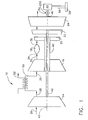
- FIG. 1 is a block diagram of a gas turbine engine assembly 10.
- Gas turbine engine 10 includes, in serial flow relationship, a low pressure compressor or booster 14, a high pressure compressor 16, a combustor 18, a high pressure turbine 20, an intermediate pressure turbine 22, and a low pressure or power turbine 24.
- Low pressure compressor or booster 14 has an inlet 26 and an outlet 28, and high pressure compressor 16 includes an inlet 30 and an outlet 32.
- Combustor 18 has an inlet 34 that is substantially coincident with high pressure compressor outlet 32, and an outlet 36.
- gas turbine engine assembly 10 is an LMS100 manufactured by General Electric Company.
- High pressure turbine 20 is coupled to high pressure compressor 16 with a first rotor shaft 40, and intermediate pressure turbine 22 is coupled to low pressure compressor 14 with a second rotor shaft 42.
- Rotor shafts 40 and 42 are each substantially coaxially aligned with respect to a longitudinal centerline axis 43 of engine 10.
- Engine 10 may be used to drive a load 44, such as a generator, which may be coupled to a power turbine shaft 46.
- the load may be coupled to a forward extension (not shown) of rotor shaft 42.
- gas turbine engine assembly 10 also includes an intercooler heat exchanger 50 that is positioned between low pressure compressor or booster 14 and high pressure compressor 16 to facilitate reducing the temperature of the air entering high pressure compressor 16.
- an intercooler facilitates increasing the efficiency of the engine while reducing the quantity of work performed by the high pressure compressor.
- At least one known intercooler heat exchanger uses ambient air or water as a cooling medium 52 to cool the air flow exiting the booster compressor.
- gas turbine engine 10 does not include intercooler heat exchanger 50.
- ambient air drawn into low pressure compressor inlet 26 is compressed and channeled downstream to high pressure compressor 16.
- High pressure compressor 16 further compresses the air and delivers high pressure air to combustor 18 where it is mixed with fuel, and the mixture is ignited to generate high temperature combustion gases.
- the combustion gases are channeled from combustor 18 to drive turbines 20, 22, and 24.
- power turbine 24 is aerodynamically coupled to intermediate pressure turbine 22 such that thrust generated by gas turbine engine 10 is used to drive power turbine 24.
- gas turbine engine assembly 10 also drives load 44.
- load 44 is coupled to power turbine 24 utilizing a thrust bearing 54, and coupled to a support structure 56 utilizing a pedestal 58, for example.
- both power turbine 24 and support structure 56 are coupled along centerline axis 43 such that gas turbine engine assembly 10 is substantially axially aligned with thrust bearing 54 and therefore load 44.
- the core gas turbine engine casing is mechanically coupled to the power turbine casing using a plurality of fasteners, such that the power turbine rotor is aerodynamically coupled to the core gas turbine engine.
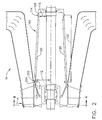
- FIG 2 is a side view of a portion of the gas turbine engine shown in Figure 1 including a support cage 100.
- Figure 3 is a perspective view of the support cage shown in Figure 2.
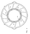
- Figure 4 is an end view of the support cage shown in Figure 2.
- support cage 100 is also referred to as a gorilla cage.
- support cage 100 is substantially frusto-conical shaped.
- frusto-conical as used herein is defined as a truncated cone or pyramid.
- support cage 100 includes a first portion 110 that is substantially circular and has a first radius 112, and a second portion 114 that is substantially circular and has a second radius 116.
- first radius 112 is larger than second radius 116.
- Support cage 100 also includes a plurality of structural members 120 that extend between, and are coupled to, first and second portions 110 and 114, respectively.
- first and second portions 110 and 114 are substantially circular.
- Each structural members 120 has a length 122 that is sized to enable support cage 100 to extend between a turbine rear frame 124 and a thrust bearing housing 126.
- each member 120 has a substantially similar length such that first portion 110 is substantially parallel to second portion 114.
- support cage 100 includes seven structural members 120 that are approximately equally spaced around a circumference of first and second portions 110 and 114, respectively. Alternatively, support cage 100 includes more or less than seven structural members.
- support cage 100 includes a first support cage structure 115 and a second support cage structure 117. More specifically, support cage 100 is fabricated in two sections 115 and 117, respectively, wherein each structure includes a plurality of members 120, such that support cage 100 can be coupled to gas turbine assembly 10.
- first support cage structure 115 is coupled to second support cage structure 117 using a welding procedure, for example.
- first support cage structure 115 is coupled to second support cage structure 117 using a plurality of mechanical fasteners.
- first support cage structure 115 extends at least 180 degrees around the power turbine centerline axis
- second support cage structure 117 extends less than 180 degrees around the power turbine centerline axis.
- first and second support cage structures 115 and 117 each extend 180 degrees around the power turbine centerline axis.
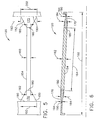
- Figure 5 is a top view of a portion of the support cage shown in Figure 2. Specifically, Figure 5 is a top view of a structural member 120.
- Figure 6 is a side view of the structural member shown in Figure 5.
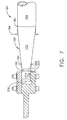
- Figure 7 is a side view of a portion of a connecting member 120 shown in Figures 5 and 6.
- Each structural member 120 includes a first attachment foot 150, a second attachment foot 152, and a connecting member 154 that extends between, and is coupled to, first and second attachment feet 150 and 152, respectively.
- Connecting member 154 has a width 160, a thickness 162, and a length 164.
- First and second attachment feet 150 and 152 each include a first portion 170 and a second portion 172 that is coupled to first portion 170.
- first and second portions 170 and 172 are unitarily formed together to form unitary first and second attachment feet 150 and 152.
- Attachment feet 150 and 152 are each coupled to connecting member 154 through a brazing and/or welding procedure, for example.
- first and second attachment feet 150 and 152, and connecting member 154 are fabricated together unitarily to form each member 120.
- each member 120 is fabricated from a plurality of pieces.
- Attachment foot first portion 170 includes a first end 180 that has a width 182 that is approximately equal to connecting member width 160, and a thickness 184 that is approximately equal to connecting member thickness 162.
- Attachment foot first portion 170 includes a second end 190 that has a width 192 that is wider than first end width 182, and a thickness 194 that is narrower than first end thickness 184.
- first portion 170 has a width and thickness 182 and 184, that are approximately equal to width and thickness 160 and 162 of connecting member 120.
- first portion 170 has a width that gradually increases from first end 180 to second end 190, and a thickness that gradually decreases from first end 180 to second end 190.
- Attachment foot second portion 172 includes a first end 200 that has a width 202 that is approximately equal to first portion width 192, and a thickness 204 that is approximately equal to first portion thickness 194.
- Attachment foot second portion 172 includes a second end 210 that has a width 212 that is approximately equal to width 202 and a thickness 214 that is approximately equal to thickness 204. Accordingly, and in the exemplary embodiment, second portion 172 has a width and thickness 200 and 204, that are approximately equal between first and second ends 200 and 210, respectively.
- support cage 100 is fabricated from a material, such as, but not limited to, AISI 4140 steel which has a relatively high modulus, good ductility (LCF capability), moderate strength, and relatively low cost.
- members 120 flex in an axial direction and therefore absorb thrust loading between gas turbine engine 10 and power turbine 24.
- members 120 are fabricated from a metallic material that is different than first and second portions 110 and 114, respectively.
- support cage 100 is coupled between a power turbine thrust bearing thrust housing 126 and an interior surface 252 of power turbine 24. More specifically, first portion 110 is coupled to a power turbine frame aft internal flange 254, and second portion 114 is coupled to an external surface of thrust bearing housing 126.
- support cage 100 is coupled to gas turbine engine 10 using a plurality of mechanical fasteners such as nuts and bolts, for example.
- support cage 100 is coupled to gas turbine engine 10 using a welding and brazing procedure for example.
- support cage 100 facilitates reducing the thrust load generated by the power turbine. More specifically, support cage 100 facilitates balancing the thrust load generated by the power turbine by transferring a portion of the thrust load back to the gas turbine engine.
- gas turbine engine assembly 10 generates approximately 1156 kN or 260,000 lbs. of thrust in an axially forward direction
- power turbine 24 generates approximately 1067 kN or 240,000 lbs in an axially aft direction.
- coupling power turbine 24 to thrust bearing 54 using support cage 100 facilitates balancing the total gas turbine assembly thrust flow between gas turbine engine 10 and power turbine 24 at the engine centerline thereby reducing thrust load distortions seen by known gas turbine engines utilizing side mounted thrust supports.
- support cage 100 facilitates reducing the gas turbine engine structural distortion thereby improving blade tip clearances within the gas turbine engine.
- the above-described support cage provides a cost-effective and highly reliable thrust assembly that includes a substantially frusto-conical shape for transferring the power turbine thrust load from the power turbine thrust bearing to the gas turbine engine thrust mounts. Accordingly, a thrust path is created between the power turbine thrust bearing and the gas turbine engine in a cost-effective manner.
- thrust assembly An exemplary embodiment of thrust assembly is described above in detail.
- the thrust assembly is not limited to the specific embodiments described herein, but rather, components of the assembly may be utilized independently and separately from other components described herein.
- the thrust assembly described herein can also be used in combination with a variety of gas turbine engines.
Landscapes
- Engineering & Computer Science (AREA)
- Mechanical Engineering (AREA)
- General Engineering & Computer Science (AREA)
- Chemical & Material Sciences (AREA)
- Combustion & Propulsion (AREA)
- Turbine Rotor Nozzle Sealing (AREA)
- Structures Of Non-Positive Displacement Pumps (AREA)
Claims (8)
- Schubanordnung (100) für eine Gasturbinentriebwerksanordnung, die ein Gasturbinentriebwerk (10), eine mit dem Gasturbinentriebwerk gekoppelte Antriebsturbine (24) und ein mit der Antriebsturbine gekoppeltes Schublager (54) enthält, wobei die Schubanordnung aufweist:einen ersten ringförmigen Abschnitt (110) mit einem ersten Radius (112), der mit der Antriebsturbine (24) gekoppelt ist;einen zweiten ringförmigen Abschnitt (114) mit einem zweiten Radius (116), der mit dem Schublager (54) gekoppelt ist, wobei sich der erste Radius von dem zweiten Radius unterscheidet; undgekennzeichnet durch:mehrere tragende Elemente (120), die sich zwischen den ersten und zweiten Abschnitten (100, 114) so erstrecken, dass die Schubanordnung (100) eine im Wesentlichen kegelstumpfförmige Form hat.
- Schubanordnung (100) nach Anspruch 1, wobei der erste Radius (112) größer als der zweite Radius (116) ist.
- Schubanordnung (100) nach Anspruch 1, wobei der erste Abschnitt (110), der zweite Abschnitt (114) und die tragenden Elemente (120) in einem Stück ausgebildet sind.
- Schubanordnung (100) nach Anspruch 1, wobei die Verbindungselemente (120) aufweisen:einen ersten Befestigungsfuß (150);einen zweiten Befestigungsfuß (152); undein Verbindungselement (154), das sich zwischen dem ersten und zweiten Verbindungsfuß erstreckt und damit gekoppelt ist.
- Schubanordnung (100) nach Anspruch 4, wobei der erste Befestigungsfuß (150) mit dem ersten Abschnitt (110) gekoppelt ist, und der zweite Befestigungsfuß (152) mit dem zweiten Abschnitt (114) gekoppelt ist.
- Schubanordnung (100) nach Anspruch 4, ferner aufweisend:ein Verbindungselement (154) mit einer Breite (160) und einer Dicke (162); undeinen ersten Befestigungsfuß (150), mit:einem ersten Ende (180) und einem zweiten Ende (190), wobei das erste Ende eine Breite (182) und eine Dicke (184) hat, die im Wesentlichen ähnlich der Breite und Dicke des Verbindungselementes ist, während das zweite Ende eine Breite (192) hat, die wesentlich größer als die Breite des Verbindungselementes ist, und eine Dicke (194), die wesentlich kleiner als die Dicke des Verbindungselementes ist.
- Schubanordnung (100) nach Anspruch 1, wobei die Schubanordnung sieben Verbindungselemente (154) aufweist.
- Gasturbinentriebwerksanordnung, aufweisend:ein Gasturbinentriebwerk (10), mit:einem ersten Kompressor (14);einem zweiten Kompressor (16) stromabwärts von dem ersten Kompressor;einer Turbine (20), die in Strömungsverbindung mit dem zweiten Kompressor gekoppelt ist;einer Antriebsturbine (24), die mit dem Gasturbinentriebwerk gekoppelt ist;einem Schublager (54), das mit der Antriebsturbine gekoppelt ist; undeiner Schubanordnung (100) nach Anspruch 1, die zwischen die Antriebsturbine (24) und das Schublager (54) gekoppelt ist.
Applications Claiming Priority (1)
| Application Number | Priority Date | Filing Date | Title |
|---|---|---|---|
| US11/006,925 US20060120854A1 (en) | 2004-12-08 | 2004-12-08 | Gas turbine engine assembly and method of assembling same |
Publications (2)
| Publication Number | Publication Date |
|---|---|
| EP1669554A1 EP1669554A1 (de) | 2006-06-14 |
| EP1669554B1 true EP1669554B1 (de) | 2007-12-26 |
Family
ID=36103767
Family Applications (1)
| Application Number | Title | Priority Date | Filing Date |
|---|---|---|---|
| EP05257401A Expired - Lifetime EP1669554B1 (de) | 2004-12-08 | 2005-12-01 | Axiallageranordnung für Gasturbinen |
Country Status (5)
| Country | Link |
|---|---|
| US (1) | US20060120854A1 (de) |
| EP (1) | EP1669554B1 (de) |
| JP (1) | JP4791809B2 (de) |
| CA (1) | CA2527641C (de) |
| DE (1) | DE602005004005T2 (de) |
Families Citing this family (10)
| Publication number | Priority date | Publication date | Assignee | Title |
|---|---|---|---|---|
| US7546742B2 (en) * | 2004-12-08 | 2009-06-16 | General Electric Company | Gas turbine engine assembly and method of assembling same |
| US7625128B2 (en) * | 2006-09-08 | 2009-12-01 | Pratt & Whitney Canada Corp. | Thrust bearing housing for a gas turbine engine |
| FR2913063B1 (fr) * | 2007-02-27 | 2012-03-16 | Snecma | Moteur d'aeronef equipe de moyens d'echange thermiques. |
| US8246292B1 (en) * | 2012-01-31 | 2012-08-21 | United Technologies Corporation | Low noise turbine for geared turbofan engine |
| US20170225172A1 (en) * | 2014-08-07 | 2017-08-10 | Emerson Electric (Us) Holding Corporation (Chile) Limitada | Monitor and Control of Tumbling Mill Using Measurements of Vibration, Electrical Power Input and Mechanical Power |
| US10422373B1 (en) | 2018-04-04 | 2019-09-24 | General Electric Company | Machine thrust bearing assembly |
| IT201800006394A1 (it) * | 2018-06-18 | 2019-12-18 | Sistema di spurgo per cassa cuscino | |
| CA3174873A1 (en) | 2020-04-09 | 2021-10-14 | Tim Sundstrom | System for controlling an internal state of a tumbling mill |
| CA3232805A1 (en) | 2021-10-09 | 2023-04-13 | Tim Sundstrom | System and method for pump control based on pump vibrations |
| US12416249B1 (en) * | 2024-10-10 | 2025-09-16 | Pratt & Whitney Canada Corp. | Turbine support case with axial spokes and heat shields |
Family Cites Families (21)
| Publication number | Priority date | Publication date | Assignee | Title |
|---|---|---|---|---|
| GB965465A (en) * | 1961-08-10 | 1964-07-29 | Rolls Royce | Improvements relating to compressor thrust bearings |
| GB928250A (en) * | 1962-01-12 | 1963-06-12 | Rolls Royce | Bearing |
| FR1338871A (fr) * | 1962-05-03 | 1963-10-04 | Rateau Soc | Perfectionnements aux dispositifs de dilatation axiale des groupes de turbines de grande puissance |
| GB1409902A (en) * | 1972-05-24 | 1975-10-15 | Rolls Royce | Stationary gas turbine power plant mounting apparatus |
| US4084861A (en) * | 1976-11-11 | 1978-04-18 | United Technologies Corporation | Thrust bearing damping means |
| US4438339A (en) * | 1980-06-30 | 1984-03-20 | General Electric Company | Low axial stiffness thrust bearing |
| FR2504980B1 (fr) * | 1981-04-29 | 1985-06-14 | Snecma | Montage de palier, en particulier pour turbomachines |
| US4578018A (en) * | 1983-06-20 | 1986-03-25 | General Electric Company | Rotor thrust balancing |
| GB2168755B (en) * | 1984-12-08 | 1988-05-05 | Rolls Royce | Improvements in or relating to gas turbine engines |
| US4872767A (en) * | 1985-04-03 | 1989-10-10 | General Electric Company | Bearing support |
| US4730977A (en) * | 1986-12-31 | 1988-03-15 | General Electric Company | Thrust bearing loading arrangement for gas turbine engines |
| US4864810A (en) * | 1987-01-28 | 1989-09-12 | General Electric Company | Tractor steam piston balancing |
| US4951461A (en) * | 1989-03-20 | 1990-08-28 | General Electric Company | Power turbine support arrangement |
| US4961310A (en) * | 1989-07-03 | 1990-10-09 | General Electric Company | Single shaft combined cycle turbine |
| US5088840A (en) * | 1990-07-26 | 1992-02-18 | United Technologies Corporation | Dashpot damper |
| US5271217A (en) * | 1992-12-09 | 1993-12-21 | General Electric Company | Mounting arrangement for a single shaft combined cycle system |
| US5376827A (en) * | 1993-05-27 | 1994-12-27 | General Electric Company | Integrated turbine-generator |
| US5735666A (en) * | 1996-12-31 | 1998-04-07 | General Electric Company | System and method of controlling thrust forces on a thrust bearing in a rotating structure of a gas turbine engine |
| US6491497B1 (en) * | 2000-09-22 | 2002-12-10 | General Electric Company | Method and apparatus for supporting rotor assemblies during unbalances |
| US6439772B1 (en) * | 2000-12-01 | 2002-08-27 | General Electric Company | Method and apparatus for supporting rotor assembly bearings |
| US6826914B2 (en) * | 2001-08-17 | 2004-12-07 | Alstom Technology Ltd | Turbogroup of a power generating plant |
-
2004
- 2004-12-08 US US11/006,925 patent/US20060120854A1/en not_active Abandoned
-
2005
- 2005-11-24 CA CA2527641A patent/CA2527641C/en not_active Expired - Fee Related
- 2005-12-01 JP JP2005347489A patent/JP4791809B2/ja not_active Expired - Fee Related
- 2005-12-01 DE DE602005004005T patent/DE602005004005T2/de not_active Expired - Lifetime
- 2005-12-01 EP EP05257401A patent/EP1669554B1/de not_active Expired - Lifetime
Also Published As
| Publication number | Publication date |
|---|---|
| JP2006161813A (ja) | 2006-06-22 |
| JP4791809B2 (ja) | 2011-10-12 |
| DE602005004005T2 (de) | 2008-12-11 |
| EP1669554A1 (de) | 2006-06-14 |
| CA2527641A1 (en) | 2006-06-08 |
| CA2527641C (en) | 2014-06-10 |
| DE602005004005D1 (de) | 2008-02-07 |
| US20060120854A1 (en) | 2006-06-08 |
Similar Documents
| Publication | Publication Date | Title |
|---|---|---|
| US8292238B2 (en) | Thrust bearing support assembly for a gas turbine engine | |
| US7815417B2 (en) | Guide vane for a gas turbine engine | |
| US10138742B2 (en) | Multi-ply finger seal | |
| EP3121384A1 (de) | Leitschaufel und leitschaufelanordnung für gasturbinenmotor | |
| US20080148708A1 (en) | Turbine engine system with shafts for improved weight and vibration characteristic | |
| US20100303608A1 (en) | Two-shaft gas turbine | |
| CA2602322C (en) | Gas turbine engine assembly and method of assembling same | |
| US9863261B2 (en) | Component retention with probe | |
| CN111878256A (zh) | 具有风扇出口导向叶片的气体涡轮引擎 | |
| EP1669554B1 (de) | Axiallageranordnung für Gasturbinen | |
| US11692444B2 (en) | Gas turbine engine rotor blade having a root section with composite and metallic portions | |
| US20140245750A1 (en) | Circumferentially retained fairing | |
| CN105765168A (zh) | 径向系紧螺栓支承弹簧 | |
| CN111878254A (zh) | 气体涡轮引擎 | |
| EP3620619A1 (de) | Turbinenaustrittsstruktur für einen gasturbinenmotor | |
| US11339684B2 (en) | Fairings for power generation machines | |
| US10161266B2 (en) | Nozzle and nozzle assembly for gas turbine engine | |
| CN111878257B (zh) | 涡轮引擎 | |
| EP3683148A1 (de) | Montagevorrichtung für einen gasturbinenmotor | |
| US12467385B1 (en) | Outlet guide vane mount | |
| CN111878255A (zh) | 具有双壁核心壳体的气体涡轮引擎 |
Legal Events
| Date | Code | Title | Description |
|---|---|---|---|
| PUAI | Public reference made under article 153(3) epc to a published international application that has entered the european phase |
Free format text: ORIGINAL CODE: 0009012 |
|
| AK | Designated contracting states |
Kind code of ref document: A1 Designated state(s): AT BE BG CH CY CZ DE DK EE ES FI FR GB GR HU IE IS IT LI LT LU LV MC NL PL PT RO SE SI SK TR |
|
| AX | Request for extension of the european patent |
Extension state: AL BA HR MK YU |
|
| 17P | Request for examination filed |
Effective date: 20061214 |
|
| 17Q | First examination report despatched |
Effective date: 20070116 |
|
| AKX | Designation fees paid |
Designated state(s): DE FR GB IT |
|
| GRAP | Despatch of communication of intention to grant a patent |
Free format text: ORIGINAL CODE: EPIDOSNIGR1 |
|
| RAP1 | Party data changed (applicant data changed or rights of an application transferred) |
Owner name: GENERAL ELECTRIC COMPANY |
|
| GRAS | Grant fee paid |
Free format text: ORIGINAL CODE: EPIDOSNIGR3 |
|
| GRAA | (expected) grant |
Free format text: ORIGINAL CODE: 0009210 |
|
| AK | Designated contracting states |
Kind code of ref document: B1 Designated state(s): DE FR GB IT |
|
| REG | Reference to a national code |
Ref country code: GB Ref legal event code: FG4D |
|
| REF | Corresponds to: |
Ref document number: 602005004005 Country of ref document: DE Date of ref document: 20080207 Kind code of ref document: P |
|
| PLBE | No opposition filed within time limit |
Free format text: ORIGINAL CODE: 0009261 |
|
| STAA | Information on the status of an ep patent application or granted ep patent |
Free format text: STATUS: NO OPPOSITION FILED WITHIN TIME LIMIT |
|
| 26N | No opposition filed |
Effective date: 20080929 |
|
| REG | Reference to a national code |
Ref country code: FR Ref legal event code: PLFP Year of fee payment: 11 |
|
| REG | Reference to a national code |
Ref country code: FR Ref legal event code: PLFP Year of fee payment: 12 |
|
| PG25 | Lapsed in a contracting state [announced via postgrant information from national office to epo] |
Ref country code: IT Free format text: LAPSE BECAUSE OF NON-PAYMENT OF DUE FEES Effective date: 20151201 |
|
| PGFP | Annual fee paid to national office [announced via postgrant information from national office to epo] |
Ref country code: GB Payment date: 20161228 Year of fee payment: 12 |
|
| PGFP | Annual fee paid to national office [announced via postgrant information from national office to epo] |
Ref country code: FR Payment date: 20161227 Year of fee payment: 12 |
|
| PGFP | Annual fee paid to national office [announced via postgrant information from national office to epo] |
Ref country code: DE Payment date: 20161229 Year of fee payment: 12 |
|
| PG25 | Lapsed in a contracting state [announced via postgrant information from national office to epo] |
Ref country code: IT Free format text: LAPSE BECAUSE OF NON-PAYMENT OF DUE FEES Effective date: 20151201 |
|
| PGFP | Annual fee paid to national office [announced via postgrant information from national office to epo] |
Ref country code: IT Payment date: 20161222 Year of fee payment: 12 |
|
| PGRI | Patent reinstated in contracting state [announced from national office to epo] |
Ref country code: IT Effective date: 20170710 |
|
| REG | Reference to a national code |
Ref country code: DE Ref legal event code: R119 Ref document number: 602005004005 Country of ref document: DE |
|
| GBPC | Gb: european patent ceased through non-payment of renewal fee |
Effective date: 20171201 |
|
| REG | Reference to a national code |
Ref country code: FR Ref legal event code: ST Effective date: 20180831 |
|
| PG25 | Lapsed in a contracting state [announced via postgrant information from national office to epo] |
Ref country code: DE Free format text: LAPSE BECAUSE OF NON-PAYMENT OF DUE FEES Effective date: 20180703 Ref country code: FR Free format text: LAPSE BECAUSE OF NON-PAYMENT OF DUE FEES Effective date: 20180102 Ref country code: IT Free format text: LAPSE BECAUSE OF NON-PAYMENT OF DUE FEES Effective date: 20171201 |
|
| PG25 | Lapsed in a contracting state [announced via postgrant information from national office to epo] |
Ref country code: GB Free format text: LAPSE BECAUSE OF NON-PAYMENT OF DUE FEES Effective date: 20171201 |