EP1669541A1 - Localisation de joints pour application dans des dispositifs comprenant un tubage enroulé - Google Patents
Localisation de joints pour application dans des dispositifs comprenant un tubage enroulé Download PDFInfo
- Publication number
- EP1669541A1 EP1669541A1 EP06075782A EP06075782A EP1669541A1 EP 1669541 A1 EP1669541 A1 EP 1669541A1 EP 06075782 A EP06075782 A EP 06075782A EP 06075782 A EP06075782 A EP 06075782A EP 1669541 A1 EP1669541 A1 EP 1669541A1
- Authority
- EP
- European Patent Office
- Prior art keywords
- fluid
- joint
- flow
- tool
- tubing
- Prior art date
- Legal status (The legal status is an assumption and is not a legal conclusion. Google has not performed a legal analysis and makes no representation as to the accuracy of the status listed.)
- Granted
Links
- 239000012530 fluid Substances 0.000 claims abstract description 174
- 238000000034 method Methods 0.000 claims description 29
- 238000001514 detection method Methods 0.000 claims description 18
- 238000004519 manufacturing process Methods 0.000 claims description 18
- 230000004044 response Effects 0.000 claims description 15
- 238000011001 backwashing Methods 0.000 claims description 10
- 230000001965 increasing effect Effects 0.000 claims description 10
- 230000001939 inductive effect Effects 0.000 claims description 6
- 230000008859 change Effects 0.000 claims description 4
- 230000008878 coupling Effects 0.000 claims description 4
- 238000010168 coupling process Methods 0.000 claims description 4
- 238000005859 coupling reaction Methods 0.000 claims description 4
- 230000011664 signaling Effects 0.000 claims description 4
- 239000000523 sample Substances 0.000 description 28
- 238000007789 sealing Methods 0.000 description 24
- 230000007704 transition Effects 0.000 description 23
- 238000004891 communication Methods 0.000 description 17
- 230000007246 mechanism Effects 0.000 description 13
- 230000006870 function Effects 0.000 description 6
- 230000015572 biosynthetic process Effects 0.000 description 4
- 238000010008 shearing Methods 0.000 description 4
- 239000012212 insulator Substances 0.000 description 3
- 230000033001 locomotion Effects 0.000 description 3
- 230000004048 modification Effects 0.000 description 3
- 238000012986 modification Methods 0.000 description 3
- 230000000903 blocking effect Effects 0.000 description 2
- 238000005516 engineering process Methods 0.000 description 2
- 239000007788 liquid Substances 0.000 description 2
- 230000008569 process Effects 0.000 description 2
- 238000005086 pumping Methods 0.000 description 2
- 230000000717 retained effect Effects 0.000 description 2
- 125000006850 spacer group Chemical group 0.000 description 2
- 239000004215 Carbon black (E152) Substances 0.000 description 1
- 229910000831 Steel Inorganic materials 0.000 description 1
- 239000006096 absorbing agent Substances 0.000 description 1
- 230000009471 action Effects 0.000 description 1
- 230000008901 benefit Effects 0.000 description 1
- 239000012267 brine Substances 0.000 description 1
- 239000004568 cement Substances 0.000 description 1
- 238000005553 drilling Methods 0.000 description 1
- 229930195733 hydrocarbon Natural products 0.000 description 1
- 150000002430 hydrocarbons Chemical class 0.000 description 1
- 230000006698 induction Effects 0.000 description 1
- 238000002347 injection Methods 0.000 description 1
- 239000007924 injection Substances 0.000 description 1
- 239000002184 metal Substances 0.000 description 1
- 239000003129 oil well Substances 0.000 description 1
- 230000000284 resting effect Effects 0.000 description 1
- 230000000630 rising effect Effects 0.000 description 1
- 239000011435 rock Substances 0.000 description 1
- 150000003839 salts Chemical class 0.000 description 1
- 230000035939 shock Effects 0.000 description 1
- HPALAKNZSZLMCH-UHFFFAOYSA-M sodium;chloride;hydrate Chemical compound O.[Na+].[Cl-] HPALAKNZSZLMCH-UHFFFAOYSA-M 0.000 description 1
- 239000010959 steel Substances 0.000 description 1
- 230000000638 stimulation Effects 0.000 description 1
- XLYOFNOQVPJJNP-UHFFFAOYSA-N water Substances O XLYOFNOQVPJJNP-UHFFFAOYSA-N 0.000 description 1
Images


Classifications
-
- E—FIXED CONSTRUCTIONS
- E21—EARTH DRILLING; MINING
- E21B—EARTH DRILLING, e.g. DEEP DRILLING; OBTAINING OIL, GAS, WATER, SOLUBLE OR MELTABLE MATERIALS OR A SLURRY OF MINERALS FROM WELLS
- E21B21/00—Methods or apparatus for flushing boreholes, e.g. by use of exhaust air from motor
- E21B21/10—Valve arrangements in drilling-fluid circulation systems
- E21B21/103—Down-hole by-pass valve arrangements, i.e. between the inside of the drill string and the annulus
-
- E—FIXED CONSTRUCTIONS
- E21—EARTH DRILLING; MINING
- E21B—EARTH DRILLING, e.g. DEEP DRILLING; OBTAINING OIL, GAS, WATER, SOLUBLE OR MELTABLE MATERIALS OR A SLURRY OF MINERALS FROM WELLS
- E21B34/00—Valve arrangements for boreholes or wells
- E21B34/06—Valve arrangements for boreholes or wells in wells
- E21B34/063—Valve or closure with destructible element, e.g. frangible disc
-
- E—FIXED CONSTRUCTIONS
- E21—EARTH DRILLING; MINING
- E21B—EARTH DRILLING, e.g. DEEP DRILLING; OBTAINING OIL, GAS, WATER, SOLUBLE OR MELTABLE MATERIALS OR A SLURRY OF MINERALS FROM WELLS
- E21B34/00—Valve arrangements for boreholes or wells
- E21B34/06—Valve arrangements for boreholes or wells in wells
- E21B34/066—Valve arrangements for boreholes or wells in wells electrically actuated
-
- E—FIXED CONSTRUCTIONS
- E21—EARTH DRILLING; MINING
- E21B—EARTH DRILLING, e.g. DEEP DRILLING; OBTAINING OIL, GAS, WATER, SOLUBLE OR MELTABLE MATERIALS OR A SLURRY OF MINERALS FROM WELLS
- E21B34/00—Valve arrangements for boreholes or wells
- E21B34/06—Valve arrangements for boreholes or wells in wells
- E21B34/14—Valve arrangements for boreholes or wells in wells operated by movement of tools, e.g. sleeve valves operated by pistons or wire line tools
-
- E—FIXED CONSTRUCTIONS
- E21—EARTH DRILLING; MINING
- E21B—EARTH DRILLING, e.g. DEEP DRILLING; OBTAINING OIL, GAS, WATER, SOLUBLE OR MELTABLE MATERIALS OR A SLURRY OF MINERALS FROM WELLS
- E21B47/00—Survey of boreholes or wells
- E21B47/09—Locating or determining the position of objects in boreholes or wells, e.g. the position of an extending arm; Identifying the free or blocked portions of pipes
- E21B47/092—Locating or determining the position of objects in boreholes or wells, e.g. the position of an extending arm; Identifying the free or blocked portions of pipes by detecting magnetic anomalies
-
- E—FIXED CONSTRUCTIONS
- E21—EARTH DRILLING; MINING
- E21B—EARTH DRILLING, e.g. DEEP DRILLING; OBTAINING OIL, GAS, WATER, SOLUBLE OR MELTABLE MATERIALS OR A SLURRY OF MINERALS FROM WELLS
- E21B47/00—Survey of boreholes or wells
- E21B47/09—Locating or determining the position of objects in boreholes or wells, e.g. the position of an extending arm; Identifying the free or blocked portions of pipes
- E21B47/095—Locating or determining the position of objects in boreholes or wells, e.g. the position of an extending arm; Identifying the free or blocked portions of pipes by detecting an acoustic anomalies, e.g. using mud-pressure pulses
-
- E—FIXED CONSTRUCTIONS
- E21—EARTH DRILLING; MINING
- E21B—EARTH DRILLING, e.g. DEEP DRILLING; OBTAINING OIL, GAS, WATER, SOLUBLE OR MELTABLE MATERIALS OR A SLURRY OF MINERALS FROM WELLS
- E21B47/00—Survey of boreholes or wells
- E21B47/12—Means for transmitting measuring-signals or control signals from the well to the surface, or from the surface to the well, e.g. for logging while drilling
- E21B47/14—Means for transmitting measuring-signals or control signals from the well to the surface, or from the surface to the well, e.g. for logging while drilling using acoustic waves
- E21B47/18—Means for transmitting measuring-signals or control signals from the well to the surface, or from the surface to the well, e.g. for logging while drilling using acoustic waves through the well fluid, e.g. mud pressure pulse telemetry
-
- E—FIXED CONSTRUCTIONS
- E21—EARTH DRILLING; MINING
- E21B—EARTH DRILLING, e.g. DEEP DRILLING; OBTAINING OIL, GAS, WATER, SOLUBLE OR MELTABLE MATERIALS OR A SLURRY OF MINERALS FROM WELLS
- E21B2200/00—Special features related to earth drilling for obtaining oil, gas or water
- E21B2200/05—Flapper valves
Definitions
- a wellbore is drilled into the subterranean producing formation or zone of interest.
- a string of pipe e.g., casing
- a string of additional pipe known as production tubing, for conducting produced fluids out of the wellbore is disposed within the cemented string of pipe.
- the subterranean strings of pipe are each comprised of a plurality of pipe sections which are threadedly joined together.
- the pipe joints often referred to as collars, are of an increased mass as compared to other portions of the pipe sections.
- Coiled tubing is a relatively small flexible tubing, usually one to three inches in diameter, which can be stored on a reel when not being used.
- the tubing is passed through an injector mechanism, and a well tool is connected to the end of the tubing.
- the injector mechanism pulls the tubing from the reel, straightens the tubing and injects it through a seal assembly at the wellhead, often referred to as a stuffing box.
- the injector mechanism injects thousands of feet of the coiled tubing with the well tool connected at the bottom end into the casing string or the production tubing string of the well.
- a fluid most often a liquid such as salt water, brine or a hydrocarbon liquid, is circulated through the coiled tubing for operating the well tool or other purpose.
- the coiled tubing injector at the surface is used to raise and lower the coiled tubing and the well tool during the service procedure and to remove the coiled tubing and well tool as the tubing is rewound on the reel at the end of the procedure.
- a joint locator tool may be lowered into the pipe string on a length of coiled tubing, and the depth of a particular pipe joint adjacent to or near the location to which the tool is positioned can be readily found on a previously recorded casing joint or collar log for the well.
- joint locator tools often do not work well in many oil field operations such as reverse circulating and fracturing. What is needed therefore, is a joint locator tool that can work in reverse circulation or fracturing operations.
- the present invention provides a downhole tool for attachment in a production string in a well bore having a casing comprising: a housing having a first fluid passage and a longitudinal axis; a valve coupled to the housing, the valve adapted to substantially block a flow of fluid through the first fluid passage in a first direction; a second fluid passage positioned through the housing in communication with the first fluid passage to permit the flow of fluid to exit through the second fluid passage; a movable cover module coupled to the first fluid passage such that in response to a first electrical signal the movable cover module substantially blocks the flow of fluid to the second fluid passage; and a flow diverting module positioned within the first fluid flow passage such that in response to an increase in fluid pressure the flow diverting module diverts the flow of fluid from the second fluid passage to the first fluid passage.
- the downhole tool may further comprise a collar locator module coupled to the housing adapted to generate the first electrical signal in response to a detection of a joint in the casing.
- the collar locator module of the downhole tool may comprise: a detection coil wound about the longitudinal axis; a plurality of magnets coupled to the detection coil and axially disposed about the longitudinal axis of the housing; and a control circuit coupled to the housing in electrical communication with the detection coil, wherein the control circuit determines whether a change in voltage from the detection coil indicates the detection of a joint and generates the first electrical signal when the joint is detected.
- the collar locator module of the downhole tool may comprise: a giant magnetoresistive field sensor; and a control circuit coupled to the housing in electrical communication with the giant magnetoresistive field sensor, wherein the control circuit determines whether a second electrical signal from the giant magnetoresistive field sensor indicates the detection of a joint and generates the first electrical signal when the joint is detected.
- the valve of the downhole tool may be adapted to permit the flow of fluid through the first fluid passage in a second direction.
- the valve of the downhole tool may further comprise a flapper element, hingedly coupled to the first fluid passage such that the flow of fluid in the first direction moves the flapper element to a closed position such that the flapper element substantially blocks the flow of fluid through a portion of the first fluid passage, and the fluid flow in the second direction moves the flapper element to an open position such that the flapper element permits fluid flow through the first fluid passage.
- the second fluid passage of the downhole tool may extend transversely through a side of the housing and comprises a nozzle to limit the flow of fluid through the second fluid passage.
- the movable cover module of the downhole tool may comprise: a hollow cylindrical piston disposed longitudinally around the first fluid passage adapted to slidably move between an open position and a closed position, wherein in the closed position the piston covers the second fluid passage to substantially block fluid from entering the second fluid passage; a spring positioned axially around the piston to exert a longitudinal biasing force upon the piston to normally maintain the piston in the open position; a third fluid passage in communication with the first fluid passage and the piston; and a solenoid valve coupled to the third fluid passage, wherein the solenoid valve is normally biased to a seat position to close the third fluid passage and in response to the first electrical signal actuates to open the third fluid passage such that fluid pressure in the third fluid passage causes the piston to move from the open position to the closed position.
- the flow diverting module of the downhole tool may comprise a hollow cylindrical assembly positioned around the first fluid passage adapted to longitudinally move between an open position and a closed position, wherein in the closed position the cylindrical assembly covers the second fluid passage to substantially block the second fluid passage.
- the downhole tool may further comprise a shear mechanism coupled to the cylindrical assembly and to the housing such that the cylindrical assembly is normally retained by the shear mechanism in the open position, wherein the shear mechanism is shearable at a predetermined force achievable by a first predetermined fluid pressure, wherein when the shear mechanism is sheared the cylindrical assembly is movable from the open position to the closed position.
- the downhole tool may further comprise a rupture disk set to rupture at a second predetermined pressure to allow the flow of fluid through the first fluid passage.
- the downhole tool may further comprise a power source and a time delay circuit for preventing power from being communicated from the power source to the collar locator module and the movable cover module until after a preselected time.
- the housing of the downhole tool may comprise an upper end adapted for connection to a length of coiled tubing whereby the tool may be moved within the production string in response to movement of the coiled tubing.
- the housing of the downhole tool may further comprise a lower end in communication with the first fluid passage, wherein the lower end is adapted for connection to other downhole tools.
- the invention provides a downhole tool for attachment in a production string in a well bore comprising: a means for detecting joints in a casing; a means for signalling the detection of joints in the casing; a means for selectively allowing backwashing operations; and a means for selectively allowing fracturing operations.
- the means for detecting joints of the downhole tool may further comprise: an electromagnetic coil means for inducing a magnetic field; a sensing means for detecting changes in the magnetic field and for sending signals in response to a detection of changes in the magnetic field; and a controller means for determining if the signals indicate the detection of joints in the casing.
- the means for signalling the detection of joints in the casing of the downhole tool may further comprise: a means for allowing fluid flow into a first fluid passage within the tool; a means for selectively allowing the fluid flow in the first fluid passage to flow through an exit port; and a means for selectively increasing fluid pressure within the first fluid passage in response to detection of joints in the casing by stopping the fluid flow through the exit port.
- the means of the downhole tool for selectively allowing backwashing operations may comprise a means for allowing fluid flow to enter the first fluid passage via a second fluid passage in response to a change in fluid flow direction.
- the means of the downhole tool for selectively allowing fracturing operations may comprise: a means for allowing fluid flow into a first fluid passage within the tool; and a means for selectively allowing the fluid flow in the first fluid passage to flow through an exit port.
- the invention provides a first method for fracturing a well having tubing positioned in a well casing, the method comprising: coupling a joint-locating tool to a lower end of the tubing, the joint-locator tool having a throughbore, a collar locator module, an exit port, a one-way valve, and a modeswitching module; injecting fluid at a first predetermined rate into the tubing such that the joint-locator tool operates in a jointlocator mode to detect the presence of joints in the well casing; inducing the mode-switching module to switch from the joint-locator mode to a fracturing mode; and injecting fracturing fluids into the tubing and through the joint-locator tool such that the well can be fractured.
- the inducing step of the method may comprise the step of increasing the fluid injection rate to a second predetermined rate to increase pressure within the throughbore such that the mode-switching module switches from the jointlocator mode to the fracturing mode.
- the inducing step of the method may further comprise plugging a fluid passageway to increase pressure within the throughbore such that the mode-switching module switches from the joint-locator mode to the fracturing mode.
- the method may further comprise injecting fluid between the casing and the tubing to operate the joint-locator tool in a back-washing mode to remove debris in the well.
- the method may further comprise injecting the fluid such that the fluid and debris flow into the bottom of a lower end of the throughbore; and moving the one-way valve into an open position to direct the fluid and debris out of an upper end of the throughbore and back up the tubing.
- the injecting fluid step of the method may comprise: injecting the fluid into an upper end of the throughbore; and positioning the one-way valve into a closed position such that fluid entering the throughbore is diverted to the exit port.
- the injecting fluid step of the method may further comprise: detecting a joint with the collar locator module; closing the exit port to increase fluid pressure within the throughbore; recording the increase in fluid pressure to signal the position of the joint; and opening the exit port.
- the inducing step of the method may further comprise: increasing fluid pressure within the throughbore; shearing a shearing mechanism in response to the increased fluid pressure; moving a cover to block flow of fluid to the exit port thereby further increasing fluid pressure within the throughbore; and rupturing a rupture disk positioned in the throughbore to allow the fluid to flow through the throughbore.
- the invention provides a second method for removing debris from a well bore having tubing positioned in well casing, the method comprising: coupling a joint-locating tool to a lower end of the tubing, the joint-locator tool having a throughbore, a fluid ejection port, a collar locator module, a one-way valve, and an exit port; injecting fluid into the tubing such that the jointlocator tool operates in a joint-locator mode to detect the presence of joints in the well casing; and injecting fluid between the well casing and the tubing to operate the joint-locator tool in a back-washing mode to remove debris in the well.
- the injecting fluid into the tubing step of the method may comprise: injecting the fluid into an upper end of the throughbore; positioning the one-way valve into a closed position such that fluid entering the throughbore is diverted to the exit port.
- the injecting fluid into the tubing step of the method may further comprise: detecting a joint with the collar locator module; closing the exit port to increase fluid pressure within the throughbore in response to detecting the joint; recording the increase in fluid pressure to signal the position of the joint; and opening the exit port.
- the method may further comprise: injecting the fluid such that the fluid and debris flow into a bottom portion of a lower end of the throughbore; and moving the one-way valve to an open position to direct the fluid and debris out of an upper end of the throughbore and back up the tubing.
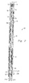
- a well 10 is schematically illustrated along with a coiled tubing injector 12 and a truck mounted coiled tubing reel assembly 14.
- the well 10 includes a wellbore 16 having a casing string 18 cemented therein in a conventional manner.
- a string of production tubing or "production string” 20 is also shown installed in well 10 within casing string 18.
- Production string 20 may be made up a plurality of tubing sections 22 connected by a plurality joints or collars 24 in a manner known in the art.
- a length of coiled tubing 26 is shown positioned in production string 20.
- One embodiment of the present invention uses a tubing collar or joint locator which is generally designated by the numeral 28 and is attached to the lower end of the coiled tubing 26.
- One or more well tools 30 may be attached below the joint locator 28.
- the coiled tubing 26 is inserted into the well 10 by the injector 12 through a stuffing box 32 attached to an upper end of the production string 20.
- the stuffing box 32 functions to provide a seal between the coiled tubing 26 and the production string 20 whereby pressurized fluids within the well 10 are prevented from escaping to the atmosphere.
- a circulating fluid of removal conduit 34 having a shutoff valve 36 therein may be sealingly connected to the top of the casing string 18. Fluid circulated into the well 10 through the coiled tubing 26 is removed from the well 10 through the conduit 34 and a valve 36 and routed to a pit, tank or other fluid accumulator.
- a coiled tubing annulus 37 may also be defined to be between the coil tubing 26 and the production string 20.
- the coiled tubing injector 12 may be of a kind known in the art and functions to straighten the coiled tubing 26 and inject it into the well 10 through the stuffing box 32 as previously mentioned.
- the coiled tubing injector 12 comprises a straightening mechanism 38 having a plurality of internal and a coiled tubing drive mechanism inserting the coiled tubing 26 into coiled tubing 26 or lowering it removing the coiled tubing 26 from the rewound on the reel assembly 14.
- a depth 44 is connected to the drive mechanism 42 and functions to continuously measure the length of the coiled tubing 26 within the well 10 and provide that information to an electronic data acquisition system 46 which is part of the reel assembly 14 through an electric transducer (not shown) and an electric cable 48.
- the truck mounted reel assembly 14 may include a reel 50 on which the coiled tubing 26 is wound.
- a guide wheel 52 may also be provided for guiding coiled tubing 26 on and off reel 50.
- a conduit assembly 54 is connected to the end of coiled tubing 26 on reel 50 by a swivel system (not shown).
- a shut-off valve 56 is disposed in conduit assembly 54, and the conduit assembly is connected to a fluid pump (not shown) which pumps fluid to be circulated from the pit, tank or other fluid communicator through the conduit assembly and into coiled tubing 26.
- a fluid pressure sensing device and transducer 58 may be connected to conduit assembly 54 by guide rollers 40 therein 42 which may be used for the well 10, raising the within the well, and well 10 as it is measuring device connection 60, and the pressure sensing device may be connected to data acquisition system 46 by an electric cable 62.
- data acquisition system 46 functions to continuously record the depth of coiled tubing 26 and joint locator 28 attached thereto in the well 10 and also to record the surface pressure of fluid being pumped through the coiled tubing and joint locator as will be further described below.
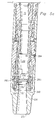
- the joint locator 28 has an outer housing 68 which is generally cylindrical in shape and encloses the various modules and components of one embodiment of the present invention.
- an upper connecting sub 70 which is adapted to, be connected to the bottom of the coiled tubing 26.
- a top opening 71 is concentrically located in the upper connecting sub 70.
- the top opening 71 defines an end of a first fluid passageway or central throughbore 72 which generally runs through the joint locator 28 along a vertical or longitudinal axis 74.
- a collar locator module 76 Positioned below the upper connecting sub 70, and located within the outer housing 68, is a collar locator module 76 which is a module designed to detect location of collars or joints within the well casing.
- the collar locator module 76 discussed in reference to the illustrative embodiment uses the principal of Faraday induction. Such technology employs a strong magnet to generate a magnetic field and a coil in which a voltage is induced due to the motion of the coil through the magnetic field perturbation caused by the magnetic discontinuity created by a gap between two sections of casing. The gap in the casing indicates the presence of a joint or collar in the casing.
- the collar locator module 76 may be coupled to a power source, such as a battery pack 78.
- an electronic controller 79 is coupled to the battery pack 78.
- the electronic controller 79 contains the circuits and control chips for determining when the magnetic discontinuity represents a joint and generates an electrical signal in response to such a determination.
- a coil and magnet section 80 containing a magnet and coil, may be positioned within the outer housing 68 and below the battery pack 78.
- the coil and magnet section 80 is in electronic communication with the battery pack 78 and the electronic controller 79.
- the collar locator module 76 comprises the battery pack 78, the electronic controller 79, the coil and magnet section 80, and the associated wiring (not shown) between the components.
- a mechanical section 81 may be located within the outer housing 68 and below the coil and magnet section 80. As will be explained in detail below, the mechanical section 81 contains a plurality of fluid passages, valves and ports which mechanically control the fluid flow and, thus operation of the joint locator 28.
- a one-way valve is coupled to the interior of the central throughbore 72.
- the one-way valve is a flapper valve 82.
- the flapper valve 82 when used in a "backwashing" mode, allows fluid to flow in an upwardly direction through the central throughbore 72. In another operational mode, the flapper valve 82 is normally biased to prevent fluid from flowing in a downwardly direction.
- the fluid may exit through a second fluid passage, such as an exit port 83.
- a movable cover module 84 inside the central throughbore 72 operates to block the flow of fluid from entering the exit port 83, resulting in an increase in pressure within the central throughbore 72.
- a separate flow diverting module 85 operates to divert the flow of fluid from the exit port 83 and forces the fluid to flow through the flapper valve 82 and through central throughbore 72.
- the upper connecting sub 70 may be adapted for connecting to a well string in a conventional manner.
- the upper connecting sub 70 may have a threaded inside surface 88 to connect to a tool string or coiled tubing 26.
- a lower end of the upper connecting sub 70 may be connected to a cylindrical shaped electronic housing 90 by means of a threaded connection 92.
- a sealing means such as a plurality of O-rings 94a-94b provide a sealing engagement between the upper connecting sub 70 and the electronic housing 90.
- the electronic housing 90 is a subsection of the outer housing 68 and encases the battery pack 78 and the electronic controller 79.
- an upper flow tube 96 running down from the upper connecting sub 70 to an upper transition sub 98 (Fig. 3b).
- the upper flow tube 96 defines a portion of the central throughbore 72.
- a pair of O-rings 100a-100b provide a sealing engagement between the flow tube 96 and the upper connecting sub 70.
- the battery pack 78 is generally cylindrical in shape.
- the battery pack 78 may comprise a battery housing 102 with a plurality of tubular battery chambers (not shown).
- a battery pack cap assembly 104a which may contain a separate waferboard 104b, or in alternative embodiments contain integrated power leads.
- the waferboard 104b may contain power leads from each battery chamber so that each battery chamber may be connected in a conventional manner.
- An electric power source such as a plurality of batteries may be disposed in each battery chamber.
- each battery there are eight battery chambers with four batteries in each chamber and each battery is an AA size battery
- each battery is an AA size battery
- the spring housing contains a spring (not shown) to bias the batteries in a conventional manner so the proper electrical connections are made between the batteries and the end caps.
- An outer surface 106 of the battery housing 102 is flat to create a space 107 for the electronic controller 79 (Fig. 2), which in one embodiment, may be a printed circuit board (PCB) 108.
- the printed circuit board 108 may be attached to the surface 106 by means of a plurality of screws 110a and 110b. The details of the printed circuit board 108 are discussed below in reference to Fig. 4.
- an electrical connection may be formed between the printed circuit board 108 and the electromagnetic coil assembly 130 via the other set of probes, the corresponding probe contacts, and the associated wiring. Since the probes, probe contacts and associated wires are conventional, they will not be described in further detail.
- FIG. 3b Another set of probes and the corresponding probe contacts allow for an electrical connection between the printed circuit board 108 and a solenoid valve assembly 132 (Fig. 3b).
- a set of wires (not shown) run between the probe contacts and the printed circuit board 108.
- Another set of wires (not shown) also run between the probes and the solenoid valve assembly 132.
- a lower end of the electronic housing 90 is coupled to a generally cylindrical coil housing 118 by a threaded connection 120.
- the coil housing 118 is also a subsection of the outer housing 68.
- a plurality of O-rings 133a-133b provide for a seal between the electronic housing 90 and the coil housing 118.
- a spring 134 may be positioned between the probe housing 126 and a washer 138 in the coil housing 118 to provide a biasing means for biasing the probes and contact probes upwardly. It will be seen by those skilled in the art that biasing in this manner will keep each probe contact in electrical contact with the corresponding probe. In this way, the proper electrical connection is made between the printed circuit board 108 and the electromagnetic coil assembly 130 and also with the solenoid valve assembly 132.
- the electromagnetic coil assembly 130 is positioned in coil housing 118 below the washer 138.
- the electromagnetic coil assembly 130 is of a kind generally known in the art having a coil, magnets and rubber shock absorbers (not shown).
- the electromagnetic coil assembly 130, the battery pack 78, the printed circuit board 108 and the probes are part of the collar locator module 76 used in the illustrative embodiment.
- the upper flow tube 96 extends downwardly from the upper connecting sub 70 to the upper transition sub 98, where it is coupled to the upper transition sub 98.
- a sealing means such as plurality of Orings 142a and 142b provide a sealing engagement between the upper transition sub 98 and the upper flow tube 96.
- the coil housing 118 is also connected to the upper transition sub 98 by means of a threaded connection 144.
- a plurality of O-rings 146a and 146b provide a sealing engagement between the coil housing 118 and the upper transition sub 98.
- a bore 148 is axially located in the upper transition sub 98.
- the bore 148 forms a portion of the throughbore 72 and is in communication with the interior of the upper flow tube 96.
- the bore 148 has a top portion 150 which is substantially axially centered along the vertical axis 74 of the joint locator 28.
- the bore 148 also has an angularly disposed central portion 152 connecting to a longitudinally extending lower portion 154.
- lower portion 154 of bore 148 is off center with respect to the top portion 150 and the central axis of joint locator 28.
- a lower flow tube 156 extends into the lower portion 154 of the bore 148 and connects to the upper transition sub 98.
- a sealing means such as an O-ring 159, provides sealing engagement between the lower flow tube 156 and the upper transition sub 98.
- the bottom end of lower flow tube 156 extends into a bore 160 in a lower transition housing 161.
- a sealing means such as an O-ring 162, provides sealing engagement between the lower flow tube 156 and the lower transition housing 161.
- a solenoid valve housing 164 which is a sub-component of the outer housing 68, may be positioned below the upper transition sub 98.
- the solenoid valve housing 164 may be coupled to the upper transition sub 98 by means of a threaded connection 166.
- the solenoid valve housing 164 is generally cylindrical, the bottom portion 170 of the solenoid valve housing 164 is stepped radially inwardly to create a seat 172. An upper rim 174 of the lower transition housing 161 fits on the seat 172.
- the bottom portion 170 of the solenoid valve housing 164 surrounds an exterior surface 176 of the lower transition housing 161 to create a threaded connection with the solenoid valve housing 164.
- a sealing means such as a plurality of Orings 178a and 178b provides a sealing engagement between the solenoid valve housing 164 and the lower transition housing 161.
- the solenoid valve assembly 132 which may be disposed within the solenoid valve housing 164, may be of a kind known in the art having an electric solenoid 182 which actuates a valve portion 184.
- the solenoid valve assembly 132 may be adapted for coupling to fluid passageways 186 and 188 in the lower transition housing 161.
- the solenoid valve assembly 132 may also be adapted for connecting to a plurality of vent ports 190a and 190b, which are disposed in the solenoid valve housing 164.
- the solenoid valve assembly 132 may be configured and positioned so that when it is in a closed position, communication between the passageway 186 and passageway 188 is prevented. In this situation, passageway 188 is in communication with vent ports 190a and 190b.
- solenoid valve assembly 132 When solenoid valve assembly 132 is in the open position, the passageway 186 and the passageway 188 are placed in communication with one another, and the passageway 188 is no longer in communication with the vent ports
- the bore 160 is part of the central throughbore 72 and is in communication with the interior of the lower flow tube 156.
- the bore 160 has a top portion 191 which extends longitudinally to an angularly disposed central portion 192.
- the central portion 192 connects to a substantially axially centered lower portion 194.
- the top portion 191 of bore 160 is off center with respect to the lower portion 194 and the central axis 74 of illustrated embodiment.
- the lower transitional housing 161 has the passageway 186 extending between an opening 195 on the inside surface of the central portion 192 and an upper surface 198.
- a screen 196 covers the opening 195 to prevent the passageway 186 from becoming clogged.
- the passageway 188 extends between the upper surface 198 and a lower surface 200 of the lower transitional housing 161.
- the lower end of the passageway 188 is in communication with a top surface 202 of a piston 204.
- the solenoid valve housing 164 is stepped radially inwardly to form an external shoulder 206.
- a piston housing 208 is positioned below the external shoulder 206 and may be threadedly attached to the solenoid valve housing 164.
- the piston housing 208 is a subcomponent of the outer housing 68.
- a sealing means such as an O-ring 210, provides sealing engagement between the solenoid valve housing 164 and the piston housing 208.
- a split ring assembly having two split ring halves 212a and 212b fits in a groove 214 defined on the outside of lower transition housing sub 161. It will be seen by those skilled in the art that split ring assembly thus acts to lock the lower transition housing sub 161 with respect to solenoid valve housing 164.
- An O-ring 213 may be used to hold the halves 212a and 212b of the split ring in the groove 214 during assembly.
- a circulating sub 216 which is generally cylindrical in shape, is disposed below the piston housing 208.
- the circulating sub 216 has a threaded exterior surface 218 to connect to the threaded interior surface 220 of the piston housing 208.
- a bottom sub housing 224 is disposed below the circulating sub 216.
- the bottom sub housing 224 is generally cylindrical in shape and has a threaded interior surface 225 to couple to an exterior threaded surface 228 of the circulating sub 216.
- a sealing means such as an O-ring 230, may be used to provide a seal between the circulating sub 216 and the bottom sub housing 224.
- the bottom sub housing 224 has an abrupt narrowing of the interior bore 226 to create a seat 231.
- a bottom portion 232 of the bottom sub housing 224 may be adapted to be coupled to another well tool in a conventional manner. For instance, the bottom portion has an opening 233 to accept well fluids from other well tools.
- the exterior of the bottom portion 232 is tapered and has an exterior threaded surface 234 to connect to other well tools.
- the piston 204 is slidably disposed within the piston housing 208.
- the piston 204 is stepped to form a first outside diameter 236 and a second outside diameter 238 to create spring chamber 240 disposed within the piston housing 208.
- the piston 204 also has a third diameter 242 which will fit within a top bore 244 of the circulating sub 216.
- a sealing means, such as 0-ring 246 provides sealing engagement between the piston 204 and the piston housing 208.
- Another sealing means, such as 0-ring 248, provides sealing engagement between the piston 204 and the circulating sub 216.
- a biasing means such as spring 250 is positioned between a downwardly facing shoulder 252 on the piston 204 and an upper end of the circulating sub 216.
- the spring 250 biases the piston 204 upwardly towards the lower surface 200 of the lower transition housing sub 161.
- a vent port 254 is located within the wall of the piston housing 208 to equalize the pressure between spring chamber 240 and the well annulus 37 (Fig. 1). It will be seen by those skilled in the art that, when in use, the well annulus pressure is thus applied to the area of the shoulder 252 on the piston 204. It will also be seen that the top surface 202 of the piston 204 is in communication with the passageway 188 of the lower transition housing sub 161.
- the piston 204 is hollow having a first bore 256 therein and a larger second bore 258.
- the first bore 256 is part of central throughbore 72.
- a cylindrical neck 260 of the lower transition housing sub 161 extends into the second bore 258.
- a sealing means such as an 0-ring 262, provides sealing engagement between piston 204 and neck 260.
- a cylindrical flapper sleeve 264 fits within a concentric bore of the circulating sub 216.
- a sealing means such as a pair of 0-rings 266a and 266b, provides a seal between the flapper sleeve 264 and the circulating sub 216.
- the transverse exit port 83 runs through a wall of the circulating sub 216 and the flapper sleeve 264.
- a nozzle 270 may be threaded into the exit port 83 to control the flow of fluid exiting through the exit port 83.
- the piston 204 In the position of piston 204 shown in Fig 3c, the piston 204 is disposed above the exit port 83. In this position, fluid moving down the central throughbore 72 may exit through the exit port 83.
- a one-way valve such as a flapper valve or flapper 82 is hingedly coupled to the inside of the flapper sleeve 264.
- a pair of elongated slots 272 (only one of which is shown in Fig. 3c), is defined in the wall of the flapper sleeve 264 to allow the flapper 82 to swing about a hinge 274 from a horizontal position to a substantially vertical position, as shown in Fig. 5A.
- a biasing means such as a spring (not shown) surrounding a hinge pin of hinge 274 may bias the flapper 82 in a closed position.
- the flapper 82 may be a hollow cylinder enclosing a rupture disk 276. The function of the rupture disk 276 will be discussed below in reference to the operation.
- a flapper seat 278 provides a seat for the flapper when the flapper is in the horizontal position.
- the flapper seat is disposed within a flapper seal retainer 280.
- the flapper seal retainer 280 is generally cylindrical in shape and is disposed within a central bore 282 of the circulating sub 216.
- a sealing means such as an O-ring 288, provides sealing engagement between the flapper seal retainer 280 and the circulating sub 216.
- a groove 283 runs along the lower exterior surface of the flapper seal retainer 280.
- a snap ring 284 fits within the groove 283.
- the flapper seal retainer 280 may be vertically retained in place with respect to the circulating sub 216 by a shearing mechanism, such as shear pins 286a and 286b.
- FIGS. 4A and 4B there is presented a schematic of one embodiment of an electrical circuit 290 used by one embodiment of the present invention.
- electrical circuit 290 may be on printed circuit board 108.
- Power for circuit 290 is provided by battery pack 78.
- U.S. Patent Number 6,253,842 entitled Wireless Coiled Tubing Joint Locator, which is hereby fully incorporated by reference.
- the illustrative embodiment of the present invention operates in three separate modes.
- a first mode or "reverse circulation” mode the embodiment operates in a reverse flow mode to allow for "backwashing" operations within the well annulus 37.
- a second mode or “joint logging” mode the embodiment operates as a conventional joint locator to locate joints and to allow the location of these joints to be recorded.
- fracturing mode the embodiment allows well fracturing operations to proceed.
- the direction of fluid during a backwashing operation will initially be downwards along the outside of the joint locator tool 28 in the direction shown by arrows 300a and 300b.
- the fluid eventually is pumped back up the tool string and enters the joint locator tool at the opening 233 in an upwardly direction 302.
- the pressure of the rising fluid will then force the flapper 82 into a substantially vertical position as illustrated in Fig. 5a, which will allow the fluid to continue to travel up through the central throughbore 72 and on up the coiled tubing.
- the flapper 82 is used in the illustrated embodiment it is important to realize that this use is not by way of limitation and other embodiments may use different types of one-way valves.
- joint locator 28 may be attached to the coiled tubing 26 at the top connecting sub 70 as previously described.
- a well tool 30 may also be connected below joint locator 28 at the bottom sub housing 224.
- the coiled tubing 26 may be injected into well 10 and may be raised within the well using injector 12 in the known manner with corresponding movement of joint locator 28.
- joint locator 28 may be raised and lowered within production string 20.
- solenoid valve assembly 132 Once battery power is supplied to solenoid valve assembly 132, the valve portion 184 is actuated by the electric solenoid 182 to place the passageway 186 in communication with the passageway 188 of the lower transition housing sub 161. In the illustrative embodiment, this power is applied to solenoid valve assembly 132 for a period of approximately 2.9 seconds.
- solenoid valve assembly 132 briefly places the fluid pressure in the central throughbore 72 in communication with the top surface 202 of the piston 204 within the piston housing 208 via the passageways 186 and 188.
- the fluid pressure in spring chamber 240 is at annulus pressure because of vent ports 254. Therefore, the higher internal pressure of the central throughbore 72 (i.e., in one embodiment, this is about 300 to 400 psi) applied to the top surface 202 of the piston 204 forces the piston 204 downwardly such that it acts as a valve means which covers the exit port 83 in the circulating sub 216. This situation is illustrated in Fig. 5b which shows the piston 204 in a downward position to cover access to the exit port 83.
- joint locator 28 may also be configured such that the exit port 83 is normally closed and the momentary actuation of the piston 204 by the solenoid valve assembly 132 may be used to open the exit port.
- the pipe joint would be detected by a surface detectable drop in the fluid pressure. This process for detecting the location of pipe joints may be repeated as many times as desired to locate any number of pipe joints The only real limitation in this procedure is the life of the power source.
- the joint logging mode is normally conducted at a pump rate of around 1 barrel/minute.
- a user can shift to the fracturing mode by increasing the pump rate to a predetermined increased rate, such as 4 barrels/minute.
- a predetermined pressure such as 2850 psi.
- the collar locator module 76 could employ a giant magnetoresistive "GMR" digital field sensor for electromagnetically sensing the presence of pipe joints.
- GMR giant magnetoresistive
- the GMR device can sense an increase in the mass of a pipe section indicating the presence of a pipe joint as the locator moves through the wellbore.
- a GMR digital field sensor can then provide a signal to a controller or a circuit board in a manner similar to the illustrative embodiment described above.
Applications Claiming Priority (2)
| Application Number | Priority Date | Filing Date | Title |
|---|---|---|---|
| US09/977,168 US6688389B2 (en) | 2001-10-12 | 2001-10-12 | Apparatus and method for locating joints in coiled tubing operations |
| EP02256218A EP1302624B1 (fr) | 2001-10-12 | 2002-09-09 | Localisation de joints pour application dans des dispositifs comprenant un tubage enroulé |
Related Parent Applications (1)
| Application Number | Title | Priority Date | Filing Date |
|---|---|---|---|
| EP02256218A Division EP1302624B1 (fr) | 2001-10-12 | 2002-09-09 | Localisation de joints pour application dans des dispositifs comprenant un tubage enroulé |
Publications (2)
| Publication Number | Publication Date |
|---|---|
| EP1669541A1 true EP1669541A1 (fr) | 2006-06-14 |
| EP1669541B1 EP1669541B1 (fr) | 2008-05-21 |
Family
ID=25524897
Family Applications (2)
| Application Number | Title | Priority Date | Filing Date |
|---|---|---|---|
| EP02256218A Expired - Fee Related EP1302624B1 (fr) | 2001-10-12 | 2002-09-09 | Localisation de joints pour application dans des dispositifs comprenant un tubage enroulé |
| EP06075782A Expired - Fee Related EP1669541B1 (fr) | 2001-10-12 | 2002-09-09 | Localisation de joints pour application dans des dispositifs comprenant un tubage enroulé |
Family Applications Before (1)
| Application Number | Title | Priority Date | Filing Date |
|---|---|---|---|
| EP02256218A Expired - Fee Related EP1302624B1 (fr) | 2001-10-12 | 2002-09-09 | Localisation de joints pour application dans des dispositifs comprenant un tubage enroulé |
Country Status (5)
| Country | Link |
|---|---|
| US (2) | US6688389B2 (fr) |
| EP (2) | EP1302624B1 (fr) |
| CA (1) | CA2407452C (fr) |
| DE (2) | DE60220129D1 (fr) |
| NO (2) | NO330808B1 (fr) |
Cited By (4)
| Publication number | Priority date | Publication date | Assignee | Title |
|---|---|---|---|---|
| WO2009065581A1 (fr) * | 2007-11-22 | 2009-05-28 | Services Petroliers Schlumberger | Dispositif de déviation de flux pour forage |
| WO2009050517A3 (fr) * | 2007-10-19 | 2010-01-14 | Petrowell Limited | Procédé et appareil de complétion d'un puits |
| CN101798918A (zh) * | 2010-03-19 | 2010-08-11 | 中国石油大学(北京) | 一种用于邻井平行间距随钻电磁探测的计算方法 |
| CN101713285B (zh) * | 2009-11-04 | 2012-08-22 | 中国石油大学(北京) | 一种利用探管接收磁短节产生的磁信号确定钻头与直井靶点相对位置的方法 |
Families Citing this family (43)
| Publication number | Priority date | Publication date | Assignee | Title |
|---|---|---|---|---|
| US7311148B2 (en) | 1999-02-25 | 2007-12-25 | Weatherford/Lamb, Inc. | Methods and apparatus for wellbore construction and completion |
| US7334650B2 (en) * | 2000-04-13 | 2008-02-26 | Weatherford/Lamb, Inc. | Apparatus and methods for drilling a wellbore using casing |
| AU2003267553A1 (en) * | 2002-08-30 | 2004-03-19 | Sensor Highway Limited | Method and apparatus for logging a well using fiber optics |
| GB2405725B (en) | 2003-09-05 | 2006-11-01 | Schlumberger Holdings | Borehole telemetry system |
| US7348893B2 (en) | 2004-12-22 | 2008-03-25 | Schlumberger Technology Corporation | Borehole communication and measurement system |
| US7306044B2 (en) | 2005-03-02 | 2007-12-11 | Halliburton Energy Services, Inc. | Method and system for lining tubulars |
| JP2009530798A (ja) | 2006-01-05 | 2009-08-27 | イルミテックス, インコーポレイテッド | Ledから光を導くための独立した光学デバイス |
| US7789531B2 (en) | 2006-10-02 | 2010-09-07 | Illumitex, Inc. | LED system and method |
| US7510017B2 (en) * | 2006-11-09 | 2009-03-31 | Halliburton Energy Services, Inc. | Sealing and communicating in wells |
| US7622916B2 (en) | 2006-12-20 | 2009-11-24 | Schlumberger Technology Corporation | Detector |
| US7805221B2 (en) | 2007-05-17 | 2010-09-28 | Rain Bird Corporation | Automatically adjusting irrigation controller |
| US8200368B2 (en) | 2008-12-10 | 2012-06-12 | Rain Bird Corporation | Automatically adjusting irrigation controller with temperature and rainfall sensor |
| EP2240968A1 (fr) | 2008-02-08 | 2010-10-20 | Illumitex, Inc. | Systeme et procede de mise en forme de la couche emettrice |
| US20110204896A1 (en) * | 2008-06-26 | 2011-08-25 | Hong Zhang | Detecting a structure in a well |
| TW201034256A (en) | 2008-12-11 | 2010-09-16 | Illumitex Inc | Systems and methods for packaging light-emitting diode devices |
| US20100309750A1 (en) * | 2009-06-08 | 2010-12-09 | Dominic Brady | Sensor Assembly |
| US8585253B2 (en) | 2009-08-20 | 2013-11-19 | Illumitex, Inc. | System and method for color mixing lens array |
| US8449128B2 (en) | 2009-08-20 | 2013-05-28 | Illumitex, Inc. | System and method for a lens and phosphor layer |
| US8074749B2 (en) | 2009-09-11 | 2011-12-13 | Weatherford/Lamb, Inc. | Earth removal member with features for facilitating drill-through |
| US8276676B2 (en) * | 2010-02-26 | 2012-10-02 | Halliburton Energy Services Inc. | Pressure-activated valve for hybrid coiled tubing jointed tubing tool string |
| US9562409B2 (en) * | 2010-08-10 | 2017-02-07 | Baker Hughes Incorporated | Downhole fracture system and method |
| US8573304B2 (en) * | 2010-11-22 | 2013-11-05 | Halliburton Energy Services, Inc. | Eccentric safety valve |
| WO2012088323A2 (fr) | 2010-12-22 | 2012-06-28 | Weatherford/Lamb, Inc. | Élément d'élimination de terre qui comporte des caractéristiques pour faciliter le forage |
| US8733449B2 (en) | 2011-04-15 | 2014-05-27 | Hilliburton Energy Services, Inc. | Selectively activatable and deactivatable wellbore pressure isolation device |
| US8651173B2 (en) | 2011-06-09 | 2014-02-18 | Baker Hughes Incorporated | Modular control system for downhole tool |
| US8701784B2 (en) | 2011-07-05 | 2014-04-22 | Jonathan V. Huseman | Tongs triggering method |
| GB2500044B (en) * | 2012-03-08 | 2018-01-17 | Weatherford Tech Holdings Llc | Selective fracturing system |
| US8978775B2 (en) | 2012-11-28 | 2015-03-17 | Halliburton Energy Services, Inc. | Downhole valve assembly and methods of using the same |
| US9127526B2 (en) * | 2012-12-03 | 2015-09-08 | Halliburton Energy Services, Inc. | Fast pressure protection system and method |
| US20140202713A1 (en) | 2013-01-18 | 2014-07-24 | Halliburton Energy Services, Inc. | Well Intervention Pressure Control Valve |
| US9863236B2 (en) * | 2013-07-17 | 2018-01-09 | Baker Hughes, A Ge Company, Llc | Method for locating casing downhole using offset XY magnetometers |
| WO2016032517A1 (fr) | 2014-08-29 | 2016-03-03 | Schlumberger Canada Limited | Ensemble capteur magnéto-sensible à fibre optique |
| CA3013084C (fr) | 2016-02-10 | 2024-01-16 | Dreco Energy Services Ulc | Agencement de joint anti-extrusion et bloc obturateur de puits de type a machoires |
| WO2017155529A1 (fr) * | 2016-03-09 | 2017-09-14 | Halliburton Energy Services, Inc. | Système et procédé de détection et de transmission d'un statut de fluide de fond de trou |
| US9890631B2 (en) * | 2016-04-14 | 2018-02-13 | Baker Hughes, A Ge Company, Llc | Hydraulic casing collar locator |
| US10900313B2 (en) | 2016-07-26 | 2021-01-26 | Dreco Energy Services Ulc | Method and apparatus for production well pressure containment for blowout |
| US11035198B2 (en) | 2017-01-16 | 2021-06-15 | Dreco Energy Services Ulc | Multifunction blowout preventer |
| WO2018213918A1 (fr) * | 2017-05-26 | 2018-11-29 | Dreco Energy Services Ulc | Procédé et appareil d'alignement de tige |
| US10941628B2 (en) | 2017-09-25 | 2021-03-09 | Dreco Energy Services Ulc | Adjustable blowout preventer and methods of use |
| US10502026B1 (en) * | 2019-02-08 | 2019-12-10 | Vertice Oil Tools | Methods and systems for fracing |
| US10989003B2 (en) * | 2019-03-04 | 2021-04-27 | Baker Hughes Oilfield Operations Llc | System for configuring subterranean components |
| US11098545B2 (en) | 2019-03-04 | 2021-08-24 | Baker Hughes Oilfield Operations Llc | Method of configuring subterranean components |
| US11293278B2 (en) | 2020-04-22 | 2022-04-05 | Halliburton Energy Services, Inc. | Valve position sensing using electric and magnetic coupling |
Citations (7)
| Publication number | Priority date | Publication date | Assignee | Title |
|---|---|---|---|---|
| US5465787A (en) * | 1994-07-29 | 1995-11-14 | Camco International Inc. | Fluid circulation apparatus |
| US5626192A (en) * | 1996-02-20 | 1997-05-06 | Halliburton Energy Services, Inc. | Coiled tubing joint locator and methods |
| WO2001014685A1 (fr) * | 1999-08-20 | 2001-03-01 | Halliburton Energy Services, Inc. | Reduction de tiges en circulation dans un puits de forage activee par une surface electrique |
| US6253842B1 (en) * | 1998-09-01 | 2001-07-03 | Halliburton Energy Services, Inc. | Wireless coiled tubing joint locator |
| EG23200A (en) * | 2000-07-18 | 2001-07-31 | Exxon Mobil Upstream Res Co | Method for treating multiple wellbore intervals. |
| GB2358652A (en) * | 2000-01-26 | 2001-08-01 | Halliburton Energy Serv Inc | Coiled tubing joint locator |
| WO2001061146A1 (fr) * | 2000-02-15 | 2001-08-23 | Exxonmobil Upstream Research Company | Procede et dispositif de stimulation de plusieurs intervalles de formation |
Family Cites Families (16)
| Publication number | Priority date | Publication date | Assignee | Title |
|---|---|---|---|---|
| US3941190A (en) | 1974-11-18 | 1976-03-02 | Lynes, Inc. | Well control apparatus |
| US4519451A (en) * | 1983-05-09 | 1985-05-28 | Otis Engineering Corporation | Well treating equipment and methods |
| US4667736A (en) | 1985-05-24 | 1987-05-26 | Otis Engineering Corporation | Surface controlled subsurface safety valve |
| US4808925A (en) | 1987-11-19 | 1989-02-28 | Halliburton Company | Three magnet casing collar locator |
| US4911242A (en) | 1988-04-06 | 1990-03-27 | Schlumberger Technology Corporation | Pressure-controlled well tester operated by one or more selected actuating pressures |
| US5236047A (en) | 1991-10-07 | 1993-08-17 | Camco International Inc. | Electrically operated well completion apparatus and method |
| US5234053A (en) | 1992-07-16 | 1993-08-10 | Halliburton Geophysical Services, Inc. | Reeled tubing counter assembly and measuring method |
| US5429190A (en) | 1993-11-01 | 1995-07-04 | Halliburton Company | Slick line casing and tubing joint locator apparatus and associated methods |
| US5392862A (en) | 1994-02-28 | 1995-02-28 | Smith International, Inc. | Flow control sub for hydraulic expanding downhole tools |
| US5443129A (en) | 1994-07-22 | 1995-08-22 | Smith International, Inc. | Apparatus and method for orienting and setting a hydraulically-actuatable tool in a borehole |
| US5609178A (en) | 1995-09-28 | 1997-03-11 | Baker Hughes Incorporated | Pressure-actuated valve and method |
| US6003834A (en) | 1996-07-17 | 1999-12-21 | Camco International, Inc. | Fluid circulation apparatus |
| US5873414A (en) | 1997-09-03 | 1999-02-23 | Pegasus International, Inc. | Bypass valve for downhole motor |
| US6349767B2 (en) * | 1998-05-13 | 2002-02-26 | Halliburton Energy Services, Inc. | Disconnect tool |
| US6394184B2 (en) * | 2000-02-15 | 2002-05-28 | Exxonmobil Upstream Research Company | Method and apparatus for stimulation of multiple formation intervals |
| US6464006B2 (en) * | 2001-02-26 | 2002-10-15 | Baker Hughes Incorporated | Single trip, multiple zone isolation, well fracturing system |
-
2001
- 2001-10-12 US US09/977,168 patent/US6688389B2/en not_active Expired - Lifetime
-
2002
- 2002-09-09 EP EP02256218A patent/EP1302624B1/fr not_active Expired - Fee Related
- 2002-09-09 DE DE60220129T patent/DE60220129D1/de not_active Expired - Lifetime
- 2002-09-09 DE DE60226791T patent/DE60226791D1/de not_active Expired - Lifetime
- 2002-09-09 EP EP06075782A patent/EP1669541B1/fr not_active Expired - Fee Related
- 2002-10-08 NO NO20024854A patent/NO330808B1/no not_active IP Right Cessation
- 2002-10-10 CA CA002407452A patent/CA2407452C/fr not_active Expired - Lifetime
-
2003
- 2003-07-31 US US10/631,288 patent/US6877558B2/en not_active Expired - Lifetime
-
2011
- 2011-04-11 NO NO20110546A patent/NO332333B1/no not_active IP Right Cessation
Patent Citations (8)
| Publication number | Priority date | Publication date | Assignee | Title |
|---|---|---|---|---|
| US5465787A (en) * | 1994-07-29 | 1995-11-14 | Camco International Inc. | Fluid circulation apparatus |
| US5626192A (en) * | 1996-02-20 | 1997-05-06 | Halliburton Energy Services, Inc. | Coiled tubing joint locator and methods |
| US6253842B1 (en) * | 1998-09-01 | 2001-07-03 | Halliburton Energy Services, Inc. | Wireless coiled tubing joint locator |
| WO2001014685A1 (fr) * | 1999-08-20 | 2001-03-01 | Halliburton Energy Services, Inc. | Reduction de tiges en circulation dans un puits de forage activee par une surface electrique |
| GB2358652A (en) * | 2000-01-26 | 2001-08-01 | Halliburton Energy Serv Inc | Coiled tubing joint locator |
| WO2001061146A1 (fr) * | 2000-02-15 | 2001-08-23 | Exxonmobil Upstream Research Company | Procede et dispositif de stimulation de plusieurs intervalles de formation |
| EG23200A (en) * | 2000-07-18 | 2001-07-31 | Exxon Mobil Upstream Res Co | Method for treating multiple wellbore intervals. |
| WO2002006629A1 (fr) * | 2000-07-18 | 2002-01-24 | Exxonmobil Upstream Research Company | Procede pour traiter les intervalles multiples dans un trou de forage |
Non-Patent Citations (1)
| Title |
|---|
| CONNELL M ET AL: "COILED TUBING: APPLICATIONS FOR TODAY'S CHALLENGES", PETROLEUM ENGINEER INTERNATIONAL, HART PUBLICATIONS, US, vol. 72, no. 7, July 1999 (1999-07-01), pages 18 - 21, XP000831422, ISSN: 0164-8322 * |
Cited By (9)
| Publication number | Priority date | Publication date | Assignee | Title |
|---|---|---|---|---|
| WO2009050517A3 (fr) * | 2007-10-19 | 2010-01-14 | Petrowell Limited | Procédé et appareil de complétion d'un puits |
| EP2508708A1 (fr) * | 2007-10-19 | 2012-10-10 | Petrowell Limited | Procédé pour compléter un puits |
| US8833469B2 (en) | 2007-10-19 | 2014-09-16 | Petrowell Limited | Method of and apparatus for completing a well |
| US9085954B2 (en) | 2007-10-19 | 2015-07-21 | Petrowell Limited | Method of and apparatus for completing a well |
| US9359890B2 (en) | 2007-10-19 | 2016-06-07 | Petrowell Limited | Method of and apparatus for completing a well |
| WO2009065581A1 (fr) * | 2007-11-22 | 2009-05-28 | Services Petroliers Schlumberger | Dispositif de déviation de flux pour forage |
| CN101713285B (zh) * | 2009-11-04 | 2012-08-22 | 中国石油大学(北京) | 一种利用探管接收磁短节产生的磁信号确定钻头与直井靶点相对位置的方法 |
| CN101798918A (zh) * | 2010-03-19 | 2010-08-11 | 中国石油大学(北京) | 一种用于邻井平行间距随钻电磁探测的计算方法 |
| CN101798918B (zh) * | 2010-03-19 | 2013-03-13 | 中国石油大学(北京) | 一种确定邻井平行段的相对空间位置的方法 |
Also Published As
| Publication number | Publication date |
|---|---|
| US6877558B2 (en) | 2005-04-12 |
| EP1302624B1 (fr) | 2007-05-16 |
| NO20110546L (no) | 2003-04-14 |
| NO330808B1 (no) | 2011-07-25 |
| CA2407452C (fr) | 2008-06-10 |
| DE60226791D1 (de) | 2008-07-03 |
| CA2407452A1 (fr) | 2003-04-12 |
| NO20024854L (no) | 2003-04-14 |
| EP1302624A1 (fr) | 2003-04-16 |
| US20030070806A1 (en) | 2003-04-17 |
| DE60220129D1 (de) | 2007-06-28 |
| US6688389B2 (en) | 2004-02-10 |
| EP1669541B1 (fr) | 2008-05-21 |
| US20040020635A1 (en) | 2004-02-05 |
| NO20024854D0 (no) | 2002-10-08 |
| NO332333B1 (no) | 2012-09-03 |
Similar Documents
| Publication | Publication Date | Title |
|---|---|---|
| EP1302624B1 (fr) | Localisation de joints pour application dans des dispositifs comprenant un tubage enroulé | |
| CA2332241C (fr) | Localisateur de joints de raccord sans fil muni d'une bobine | |
| US9151138B2 (en) | Injection of fluid into selected ones of multiple zones with well tools selectively responsive to magnetic patterns | |
| US5626192A (en) | Coiled tubing joint locator and methods | |
| CA2259852C (fr) | Localisateur sans fil de joints de serpentins | |
| US7086463B2 (en) | Methods of downhole testing subterranean formations and associated apparatus therefor | |
| CA2866858C (fr) | Outils de puits repondant selectivement a des combinaisons magnetiques | |
| US6543540B2 (en) | Method and apparatus for downhole production zone | |
| EP0584997B1 (fr) | Système et procédé pour le fonctionnement d'un outil de fond de trou | |
| US6330913B1 (en) | Method and apparatus for testing a well | |
| US7073582B2 (en) | Method and apparatus for positioning a downhole tool | |
| US6357525B1 (en) | Method and apparatus for testing a well | |
| US20130020065A1 (en) | Downhole Smart Control System | |
| US20130024030A1 (en) | Method of Using a Downhole Smart Control System | |
| EP3019690B1 (fr) | Systèmes et procédés de détection de déplacement de soupape | |
| US20170306716A1 (en) | Coiled Tubing Degradable Flow Control Device | |
| CA2593440C (fr) | Appareil et methode de localisation des joints de tubes d'intervention enroules | |
| US11761304B1 (en) | Subsurface safety valve operation monitoring system |
Legal Events
| Date | Code | Title | Description |
|---|---|---|---|
| PUAI | Public reference made under article 153(3) epc to a published international application that has entered the european phase |
Free format text: ORIGINAL CODE: 0009012 |
|
| AC | Divisional application: reference to earlier application |
Ref document number: 1302624 Country of ref document: EP Kind code of ref document: P |
|
| AK | Designated contracting states |
Kind code of ref document: A1 Designated state(s): DE FR GB IT NL |
|
| AX | Request for extension of the european patent |
Extension state: AL LT LV MK RO SI |
|
| RIN1 | Information on inventor provided before grant (corrected) |
Inventor name: TUCKER, JAMES C. Inventor name: CONNELL, MICHAEL L Inventor name: HOWARD, ROBERT G. Inventor name: LOVE, DOUGLAS N. |
|
| 17P | Request for examination filed |
Effective date: 20061113 |
|
| AKX | Designation fees paid |
Designated state(s): DE FR GB IT NL |
|
| GRAP | Despatch of communication of intention to grant a patent |
Free format text: ORIGINAL CODE: EPIDOSNIGR1 |
|
| GRAS | Grant fee paid |
Free format text: ORIGINAL CODE: EPIDOSNIGR3 |
|
| GRAA | (expected) grant |
Free format text: ORIGINAL CODE: 0009210 |
|
| AC | Divisional application: reference to earlier application |
Ref document number: 1302624 Country of ref document: EP Kind code of ref document: P |
|
| AK | Designated contracting states |
Kind code of ref document: B1 Designated state(s): DE FR GB IT NL |
|
| REG | Reference to a national code |
Ref country code: GB Ref legal event code: FG4D |
|
| REF | Corresponds to: |
Ref document number: 60226791 Country of ref document: DE Date of ref document: 20080703 Kind code of ref document: P |
|
| PLBE | No opposition filed within time limit |
Free format text: ORIGINAL CODE: 0009261 |
|
| STAA | Information on the status of an ep patent application or granted ep patent |
Free format text: STATUS: NO OPPOSITION FILED WITHIN TIME LIMIT |
|
| 26N | No opposition filed |
Effective date: 20090224 |
|
| PGFP | Annual fee paid to national office [announced via postgrant information from national office to epo] |
Ref country code: FR Payment date: 20081006 Year of fee payment: 7 |
|
| REG | Reference to a national code |
Ref country code: FR Ref legal event code: ST Effective date: 20100531 |
|
| PG25 | Lapsed in a contracting state [announced via postgrant information from national office to epo] |
Ref country code: FR Free format text: LAPSE BECAUSE OF NON-PAYMENT OF DUE FEES Effective date: 20090930 |
|
| REG | Reference to a national code |
Ref country code: DE Ref legal event code: R082 Ref document number: 60226791 Country of ref document: DE Representative=s name: WEISSE, RENATE, DIPL.-PHYS. DR.-ING., DE |
|
| PGFP | Annual fee paid to national office [announced via postgrant information from national office to epo] |
Ref country code: DE Payment date: 20170726 Year of fee payment: 16 Ref country code: GB Payment date: 20170707 Year of fee payment: 16 Ref country code: IT Payment date: 20170913 Year of fee payment: 16 |
|
| PGFP | Annual fee paid to national office [announced via postgrant information from national office to epo] |
Ref country code: NL Payment date: 20170913 Year of fee payment: 16 |
|
| REG | Reference to a national code |
Ref country code: DE Ref legal event code: R119 Ref document number: 60226791 Country of ref document: DE |
|
| REG | Reference to a national code |
Ref country code: NL Ref legal event code: MM Effective date: 20181001 |
|
| GBPC | Gb: european patent ceased through non-payment of renewal fee |
Effective date: 20180909 |
|
| PG25 | Lapsed in a contracting state [announced via postgrant information from national office to epo] |
Ref country code: NL Free format text: LAPSE BECAUSE OF NON-PAYMENT OF DUE FEES Effective date: 20181001 |
|
| PG25 | Lapsed in a contracting state [announced via postgrant information from national office to epo] |
Ref country code: DE Free format text: LAPSE BECAUSE OF NON-PAYMENT OF DUE FEES Effective date: 20190402 Ref country code: IT Free format text: LAPSE BECAUSE OF NON-PAYMENT OF DUE FEES Effective date: 20180909 |
|
| PG25 | Lapsed in a contracting state [announced via postgrant information from national office to epo] |
Ref country code: GB Free format text: LAPSE BECAUSE OF NON-PAYMENT OF DUE FEES Effective date: 20180909 |