EP1669527A1 - Espagnolette lock for suitcase - Google Patents
Espagnolette lock for suitcase Download PDFInfo
- Publication number
- EP1669527A1 EP1669527A1 EP05292516A EP05292516A EP1669527A1 EP 1669527 A1 EP1669527 A1 EP 1669527A1 EP 05292516 A EP05292516 A EP 05292516A EP 05292516 A EP05292516 A EP 05292516A EP 1669527 A1 EP1669527 A1 EP 1669527A1
- Authority
- EP
- European Patent Office
- Prior art keywords
- locking
- hooks
- link
- plate
- lock according
- Prior art date
- Legal status (The legal status is an assumption and is not a legal conclusion. Google has not performed a legal analysis and makes no representation as to the accuracy of the status listed.)
- Granted
Links
Images

Classifications
-
- E—FIXED CONSTRUCTIONS
- E05—LOCKS; KEYS; WINDOW OR DOOR FITTINGS; SAFES
- E05B—LOCKS; ACCESSORIES THEREFOR; HANDCUFFS
- E05B65/00—Locks or fastenings for special use
- E05B65/52—Other locks for chests, boxes, trunks, baskets, travelling bags, or the like
- E05B65/5207—Other locks for chests, boxes, trunks, baskets, travelling bags, or the like characterised by bolt movement
- E05B65/5215—Other locks for chests, boxes, trunks, baskets, travelling bags, or the like characterised by bolt movement sliding
- E05B65/523—Other locks for chests, boxes, trunks, baskets, travelling bags, or the like characterised by bolt movement sliding parallel to the surface on which the lock is mounted
- E05B65/5238—Other locks for chests, boxes, trunks, baskets, travelling bags, or the like characterised by bolt movement sliding parallel to the surface on which the lock is mounted parallel to the wing edge
-
- E—FIXED CONSTRUCTIONS
- E05—LOCKS; KEYS; WINDOW OR DOOR FITTINGS; SAFES
- E05B—LOCKS; ACCESSORIES THEREFOR; HANDCUFFS
- E05B17/00—Accessories in connection with locks
- E05B17/20—Means independent of the locking mechanism for preventing unauthorised opening, e.g. for securing the bolt in the fastening position
- E05B17/2007—Securing, deadlocking or "dogging" the bolt in the fastening position
- E05B17/203—Securing, deadlocking or "dogging" the bolt in the fastening position not following the movement of the bolt
- E05B17/2034—Securing, deadlocking or "dogging" the bolt in the fastening position not following the movement of the bolt moving pivotally or rotatively
-
- E—FIXED CONSTRUCTIONS
- E05—LOCKS; KEYS; WINDOW OR DOOR FITTINGS; SAFES
- E05C—BOLTS OR FASTENING DEVICES FOR WINGS, SPECIALLY FOR DOORS OR WINDOWS
- E05C1/00—Fastening devices with bolts moving rectilinearly
- E05C1/08—Fastening devices with bolts moving rectilinearly with latching action
- E05C1/10—Fastening devices with bolts moving rectilinearly with latching action with operating handle or equivalent member rigid with the latch
-
- E—FIXED CONSTRUCTIONS
- E05—LOCKS; KEYS; WINDOW OR DOOR FITTINGS; SAFES
- E05C—BOLTS OR FASTENING DEVICES FOR WINGS, SPECIALLY FOR DOORS OR WINDOWS
- E05C9/00—Arrangements of simultaneously actuated bolts or other securing devices at well-separated positions on the same wing
- E05C9/04—Arrangements of simultaneously actuated bolts or other securing devices at well-separated positions on the same wing with two sliding bars moved in opposite directions when fastening or unfastening
- E05C9/041—Arrangements of simultaneously actuated bolts or other securing devices at well-separated positions on the same wing with two sliding bars moved in opposite directions when fastening or unfastening with rack and pinion mechanism
Definitions
- the present invention relates to a lock linkage intended in particular for locking suitcases.
- Locks of this type equip two-piece suitcases foldable towards one another, and they comprise hooks integral with an edge of one of the two parts and retaining members integral with an opposite edge of the other part.
- the hooks are mounted in a fixed position on said edge, while the retaining members are movably mounted in translation. After the two foldable parts have been folded down the retaining members are capable of being driven in translation to engage in the hooks.
- the two foldable parts are held in a fixed position relative to each other.
- the retaining members are connected to a locking device via a locking rod so as to lock the retaining members in the position where they are engaged with the hooks.
- linkage locks lies in the possibility of controlling several locking devices by means of a single closing point while the other locks require a closing point locking device.
- two locking devices are controlled respectively by two closing points.
- a problem that then arises and that aims to solve the present invention is to provide a lock linkage that is not only inexpensive to manufacture but also safer.
- the present invention provides a lock linkage for locking a suitcase, said bag comprising two foldable parts, said lock comprising integral hooks of one of the two parts and integral retainers of the other part, said hooks and said retainers being respectively movable in translation relative to each other between a position in which they are engaged to hold the two parts together, and a position where they are spaced from each other to release the two parts, said lock comprising means for blocking the relative movement of said hooks and said retaining members, said locking means being controlled by at least one locking rod; according to the invention said hooks are movably mounted in translation on said one of the two parts; and said locking means comprise at least one rod integral with said lockable rod, said locking rod being intended to pivotally drive said rod, between a locking position in which said rod opposes the movement of said hooks and an unlocking position in which said link allows the movement of said hooks.
- a feature of the invention lies firstly in the implementation of mobile hooks relative to the bag portion on which they are mounted, the retainers then being mounted in a fixed position relative to the other part and secondly, in the use of a pivotally mounted link and which allows the translational locking of the hooks in a locked position and pivoted the link. In this way, few parts are necessary for the implementation of the lock linkage according to the invention.
- said link having a movable free end
- said locking rod is integral with a plate, said plate having an inclined portion forming a ramp, and in that said free end is adapted to bear on said ramp portion so as to rotate said link when said plate is driven in translation by said locking rod.
- the rod is pivotally driven via the plate, its free end coming to bear against the bearing portion inclined ramp.
- said link having a pivot point
- said plate is intended to be driven towards said pivot point, its free end sliding against said ramp portion, to carry said link in said locking position.
- said plate is held by elastic means in a position corresponding to said locking position, the elastic means then forming return means which, in the event of neutralization of the locking member and thus release of the rod locking, to maintain the plate in a position where it maintains said link in the locking position.
- said hooks are integral with a sliding plate mounted sliding in a determined direction, and said rod is locking in translation said locking plate in said locking position.
- said locking plate has an oblong slot which extends in said determined direction and inside which the free end of the rod is adapted to be guided, a notch being made in said oblong slot so that said link can cooperate with said notch in said lock position.
- said link is pivotally mounted substantially parallel to said locking plate, said free end being provided with a finger substantially perpendicular to the link and intended to be engaged in said oblong slot to come within said notch in said locking position.
- the lock object of the invention comprises a pair of hooks and a pair of corresponding locking means, the locking means of said pair being spaced from each other, and the respective rods said blocking means converge towards one another to join a common locking member.
- two locking means coupled to their corresponding hooks are adapted to be controlled by a single locking member, which not only increases the safety of the bag but also to reduce the size of the lock according to the invention.
- said common locking member is controlled by electric drive means.
- the common locking member and said convergent rods comprise a pinion / rack system, the two locking rods extending tangentially in two diametrically opposite portions of the pinion.
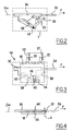
- Figure 1 shows a lock linkage 10 according to the invention and which is intended to be installed along an edge of a folding portion of a suitcase or trunk.
- the lock 10 comprises two identical sets 12,14 opposite and symmetrical to each other with respect to a plane of symmetry P, including a central point 16 at which, as will be explained below remains a locking device not shown.
- the references to the organs of the first set 12 will bear the same reference as those of the organs of the first set 14 correspondents, assigned the sign "'".
- the first set 12 has a locking plate 18 'provided with hooks 20' while the second set 14 does not include to reveal the elements that mask in Figure.
- the hooks 20 ' are engaged in retaining members 22' integral with the opposite edge of the other folding portion of the not shown suitcase.
- the locking plate 18 ' has an oblong slot 24' which extends in a direction parallel to an average line Dm joining the two sets 12, 14.
- the oblong slot 24 ' has at one of its ends a perpendicular notch 26.
- the locking plate 18 ' is slidably mounted in the same direction and is adapted to be driven in translation manually by means of a drive member formed for example of a push button, in a direction opposite to the second 14 together to release the hooks 20 'retaining members 22'.
- it is biased in translation towards the second assembly by a spring not shown to maintain, in a rest position, the hooks 20 'engaged in the retaining members 22'.
- the second assembly 14 reveals locking means 28 in translation of a locking plate identical to that of the first assembly 12, but symmetrical with respect to the plane P.
- These locking means 28 comprise a link 30 mounted articulated around the one of its ends 32, perpendicular to an axis A, a locking rod 34 and a drive plate 36 which connects the rod 30 and the rods 34.
- the first assembly 12 comprises a locking rod 34 ' extended to the second assembly 14, the two locking rods 34,34 'respectively having rack ends 35, 35' parallel to each other and integral with a single pinion 37 in which they mesh diametrically opposite.
- the pinion 37 controllable in rotation by a handle, is capable of being held in a fixed position by means of key locking and barrel for example.
- the pinion 37 is, according to a particular embodiment of the invention, controlled by means of an electric motor, for example by an electric motor.
- the rod 30 adapted to pivot around its end 32, the locking rod 34 and the drive plate 36 which is also mounted to move in translation along the average line Dm.
- the latter is solitary in translation of the locking rod 34 in the direction of the average line Dm.
- the plate 36 has an inclined portion forming a ramp 38, formed by an edge of an inclined longitudinal recess 40 along a line T, which is formed in the plate 36. This longitudinal recess 40 forms an acute angle with the locking rod. 34.
- the rod 30 which is parallel to the mean plane defined by the plate 36 has a free end 42 equipped with a transverse lug 44 which appears in FIG. 4 and which extends on one side of the link 30 in FIG. Inclined longitudinal recess 40.
- a locking pin 46 opposite the transverse pin 44 extends transversely on the other side of the link 30.
- the locking finger 46 appears projecting from the link 30, for the second set 14, and through the oblong slot 24 'of the locking plate 18' for the first set 12.
- the elements of the first set 12 are arranged symmetrically with respect to the plane of symmetry P in the second set 14, and that consequently, the free ends 42, 42 'of the links 30, 30' extend in two opposite directions as the recesses longitudinals inclined 40, 40 'of the plates 36, 36'.
- FIG. 3 shows the second assembly 14 equipped with a locking plate 18 and with transparency behind this locking plate 18, the plate 36 and its inclined longitudinal recess 40 as well as the link 30 provided with its locking finger 46 which extends in front of the plane of the Figure through the oblong slot 24.
- the locking plate 18 is symmetrical with the locking plate 18 'of the first set 12 with respect to the plane of symmetry P.
- the locking plate 18 'of the first assembly 12 is locked in translation thanks to the locking pin 46' which is engaged in the perpendicular notch 26 ', the two opposite edges of the perpendicular notch 26' being capable of abutting against the locking pin 46 '.
- first and second assemblies 12, 14 have return springs 50, 50 'which force respectively the two plates 36, 36' towards each other, respectively in directions F and F 'when the locking rods 34, 34 'are free to engage the locking fingers 46, 46' in their respective perpendicular slots 26, 26 '.
- return springs 50, 50 allow, in case of break-in and neutralization of the pinion 37, to maintain the rods 30, 30' in the locking position.
- the rack and pinion system is replaced by a cam system.
- the two locking rods then have a free end of support and they extend towards one another, their free ends facing each other. Furthermore, between the two free ends, is interposed a rotary ring whose peripheral portion has two opposite cut edges which move away from each other in an inverse helix and forming a helical ramp and this, at least on a part of the circumference of the crown.
- the ring is moved by means of a central shaft extended substantially parallel to said rods and at a distance so as to insert between said free ends said peripheral portion, said free ends respectively bearing against said opposite edges.
- the linkage lock comprises two pairs of hooks, each hook actually comprising two notches integral with a single locking plate, and two pairs of corresponding locking means. adapted to come respectively lock the locking plates.
- the locking means of one of the pairs are respectively coupled with the locking means of the other pair of locking means and the locking means coupled in pairs are spaced apart from each other.
- the plates of the locking means coupled together are respectively integral with a single rod, so that the two rods of the two pairs of locking means can converge towards one another so that they can be actuated together according to a aforementioned modes.
Abstract
Description
La présente invention se rapporte à une serrure à tringlerie destinée notamment au verrouillage des valises.The present invention relates to a lock linkage intended in particular for locking suitcases.
Des serrures de ce type équipent des valises en deux parties rabattables l'une vers l'autre, et elles comprennent des crochets solidaires d'un bord de l'une des deux parties et des organes de retenue solidaires d'un bord opposé de l'autre partie. Les crochets sont montés en position fixe sur ledit bord, tandis que les organes de retenue sont montés mobiles en translation. Après que les deux parties rabattables ont été rabattues les organes de retenue sont susceptibles d'être entraînés en translation pour venir en prises dans les crochets.Locks of this type equip two-piece suitcases foldable towards one another, and they comprise hooks integral with an edge of one of the two parts and retaining members integral with an opposite edge of the other part. The hooks are mounted in a fixed position on said edge, while the retaining members are movably mounted in translation. After the two foldable parts have been folded down the retaining members are capable of being driven in translation to engage in the hooks.
De la sorte, les deux parties rabattables sont maintenues en position fixe l'une par rapport à l'autre. En outre, les organes de retenue sont reliés à un dispositif de verrouillage par l'intermédiaire d'une tringle verrouillable de façon à verrouiller les organes de retenue dans la position où ils sont en prise avec les crochets.In this way, the two foldable parts are held in a fixed position relative to each other. In addition, the retaining members are connected to a locking device via a locking rod so as to lock the retaining members in the position where they are engaged with the hooks.
Un avantage des serrures à tringlerie réside notamment dans la possibilité de commander plusieurs dispositifs de verrouillage au moyen d'un seul point de fermeture alors que les autres serrures nécessitent un point de fermeture par dispositif de verrouillage. Usuellement, deux dispositifs de verrouillage sont commandés respectivement par deux points de fermeture.One advantage of the linkage locks lies in the possibility of controlling several locking devices by means of a single closing point while the other locks require a closing point locking device. Usually, two locking devices are controlled respectively by two closing points.
On pourra se référer notamment au document FR 2 788 548, dans lequel il est décrit une telle serrure.Reference may be made in particular to document FR 2 788 548, in which such a lock is described.
Un inconvénient de ces serrures à tringlerie résident d'une part dans la quantité de pièces à mettre en oeuvre et dans leur complexité ce qui les rend relativement coûteuses à fabriquer, et d'autre part dans leur manque de sûreté. En effet, dès lors que le dispositif de verrouillage est neutralisé les organes de retenue sont susceptibles d'être écartés des crochets et la valise ouverte.A disadvantage of these locks linkage reside on the one hand in the amount of parts to implement and in their complexity which makes them relatively expensive to manufacture, and secondly in their lack of safety. Indeed, since the locking device is neutralized the retaining members are likely to be removed from the hooks and the bag open.
Un problème qui se pose alors et que vise à résoudre la présente invention, est de fournir une serrure à tringlerie qui soit non seulement peu coûteuse à fabriquer mais aussi qui soit plus sûre.A problem that then arises and that aims to solve the present invention is to provide a lock linkage that is not only inexpensive to manufacture but also safer.
Dans ce but, la présente invention propose une serrure à tringlerie destinée au verrouillage d'une valise, ladite valise comprenant deux parties rabattables, ladite serrure comprenant des crochets solidaires de l'une des deux parties et des organes de retenue solidaires de l'autre partie, lesdits crochets et lesdits organes de retenue étant respectivement mobiles en translation les uns par rapport aux autres entre une position dans laquelle ils sont en prise pour maintenir ensemble les deux parties, et une position où ils sont écartés les uns des autres pour libérer les deux parties, ladite serrure comprenant des moyens de blocage du déplacement relatif desdits crochets et desdits organes de retenue, lesdits moyens de blocage étant commandés par au moins une tringle verrouillable ; selon l'invention lesdits crochets sont montés mobiles en translation sur ladite une des deux parties ; et lesdits moyens de blocage comprennent au moins une biellette solidaire de ladite tringle verrouillable, ladite tringle verrouillable étant destinée à entraîner en pivotement ladite biellette, entre une position de verrouillage dans laquelle ladite biellette s'oppose au mouvement desdits crochets et une position de déverrouillage dans laquelle ladite biellette autorise le mouvement desdits crochets.For this purpose, the present invention provides a lock linkage for locking a suitcase, said bag comprising two foldable parts, said lock comprising integral hooks of one of the two parts and integral retainers of the other part, said hooks and said retainers being respectively movable in translation relative to each other between a position in which they are engaged to hold the two parts together, and a position where they are spaced from each other to release the two parts, said lock comprising means for blocking the relative movement of said hooks and said retaining members, said locking means being controlled by at least one locking rod; according to the invention said hooks are movably mounted in translation on said one of the two parts; and said locking means comprise at least one rod integral with said lockable rod, said locking rod being intended to pivotally drive said rod, between a locking position in which said rod opposes the movement of said hooks and an unlocking position in which said link allows the movement of said hooks.
Ainsi, une caractéristique de l'invention réside d'une part, dans la mise en oeuvre de crochets mobiles par rapport à la partie de valise sur lesquels ils sont montés, les organes de retenue étant alors montés en position fixe par rapport à l'autre partie et d'autre part, dans l'emploi d'une biellette montée pivotante et qui permet le blocage en translation des crochets dans une position de verrouillage et pivotée de la biellette. De la sorte, peu de pièces sont nécessaires pour la mise en oeuvre de la serrure à tringlerie conforme à l'invention.Thus, a feature of the invention lies firstly in the implementation of mobile hooks relative to the bag portion on which they are mounted, the retainers then being mounted in a fixed position relative to the other part and secondly, in the use of a pivotally mounted link and which allows the translational locking of the hooks in a locked position and pivoted the link. In this way, few parts are necessary for the implementation of the lock linkage according to the invention.
Avantageusement, ladite biellette présentant une extrémité libre mobile, ladite tringle verrouillable est solidaire d'une platine, ladite platine présentant une portion inclinée formant rampe, et en ce que ladite extrémité libre est adaptée à prendre appui sur ladite portion formant rampe de façon à faire pivoter ladite biellette lorsque ladite platine est entraînée en translation par ladite tringle verrouillable. De la sorte, la biellette est entraînée en pivotement par l'intermédiaire de la platine, son extrémité libre venant à frottement prendre appui contre la portion inclinée formant rampe.Advantageously, said link having a movable free end, said locking rod is integral with a plate, said plate having an inclined portion forming a ramp, and in that said free end is adapted to bear on said ramp portion so as to rotate said link when said plate is driven in translation by said locking rod. In this way, the rod is pivotally driven via the plate, its free end coming to bear against the bearing portion inclined ramp.
Selon un mode de mise en oeuvre de l'invention particulièrement avantageux, ladite biellette présentant un point de pivotement, ladite platine est destinée à être entraînée vers ledit point de pivotement, son extrémité libre en appui glissant contre ladite portion formant rampe, pour porter ladite biellette dans ladite position de verrouillage.According to a particularly advantageous embodiment of the invention, said link having a pivot point, said plate is intended to be driven towards said pivot point, its free end sliding against said ramp portion, to carry said link in said locking position.
En outre, ladite platine est maintenue par des moyens élastiques dans une position correspondant à ladite position de verrouillage, les moyens élastiques formant alors des moyens de rappel qui permettent, en cas de neutralisation de l'organe de verrouillage et donc de libération de la tringle de verrouillage, de maintenir la platine dans une position où elle maintient ladite biellette dans la position de verrouillage.In addition, said plate is held by elastic means in a position corresponding to said locking position, the elastic means then forming return means which, in the event of neutralization of the locking member and thus release of the rod locking, to maintain the plate in a position where it maintains said link in the locking position.
Selon un mode de réalisation de l'invention avantageux, lesdits crochets sont solidaires d'une plaque de verrouillage montée coulissante selon une direction déterminée, et ladite biellette vient bloquer en translation ladite plaque de verrouillage dans ladite position de verrouillage. De la sorte, il est d'une part possible de monter en parallèle plusieurs crochets sur une même plaque de verrouillage, ce qui permet d'assurer une plus grande sûreté, et d'autre part de mieux guider les crochets en translation par l'intermédiaire de la plaque de verrouillage qui par exemple coulisse entre deux surfaces d'appui.According to an advantageous embodiment of the invention, said hooks are integral with a sliding plate mounted sliding in a determined direction, and said rod is locking in translation said locking plate in said locking position. In this way, it is firstly possible to mount several hooks in parallel on the same locking plate, which allows to ensure greater safety, and secondly to better guide the hooks in translation by the intermediate locking plate which for example slides between two bearing surfaces.
De façon préférentielle, ladite plaque de verrouillage présente une lumière oblongue qui s'étend selon ladite direction déterminée et à l'intérieur de laquelle l'extrémité libre de la biellette est adaptée à être guidée, une encoche étant pratiquée dans ladite lumière oblongue de façon que ladite biellette puisse coopérer avec ladite encoche dans ladite position de verrouillage. En outre, selon un mode de mise en oeuvre particulier, ladite biellette est montée pivotante sensiblement parallèlement à ladite plaque de verrouillage, ladite extrémité libre étant munie d'un doigt sensiblement perpendiculaire à la biellette et destiné à être engagé dans ladite lumière oblongue pour venir à l'intérieur de ladite encoche dans ladite position de verrouillage.Preferably, said locking plate has an oblong slot which extends in said determined direction and inside which the free end of the rod is adapted to be guided, a notch being made in said oblong slot so that said link can cooperate with said notch in said lock position. In addition, according to a particular embodiment, said link is pivotally mounted substantially parallel to said locking plate, said free end being provided with a finger substantially perpendicular to the link and intended to be engaged in said oblong slot to come within said notch in said locking position.
Par ailleurs, selon une variante d'exécution particulièrement avantageuse la serrure objet de l'invention comprend une paire de crochets et une paire de moyens de blocage correspondants, les moyens de blocage de ladite paire étant espacés les uns des autres, et les tringles respectives desdits moyens de blocage convergent l'une vers l'autre pour rejoindre un organe de verrouillage commun. De la sorte, deux moyens de blocage couplés à leurs crochets correspondants sont adaptés à être commandé par un seul et unique organe de verrouillage, ce qui permet non seulement d'augmenter la sûreté de la valise mais aussi de réduire l'encombrement de la serrure conforme à l'invention. Préférentiellement, ledit organe de verrouillage commun est commandé par des moyens de motorisation électriques.Furthermore, according to a particularly advantageous embodiment of the lock object of the invention comprises a pair of hooks and a pair of corresponding locking means, the locking means of said pair being spaced from each other, and the respective rods said blocking means converge towards one another to join a common locking member. In this way, two locking means coupled to their corresponding hooks are adapted to be controlled by a single locking member, which not only increases the safety of the bag but also to reduce the size of the lock according to the invention. Preferably, said common locking member is controlled by electric drive means.
Avantageusement, l'organe de verrouillage commun et lesdites tringles convergentes comprennent un système pignon/crémaillères, les deux tringles de verrouillage s'étendant tangentiellement dans deux parties diamétralement opposées du pignon.Advantageously, the common locking member and said convergent rods comprise a pinion / rack system, the two locking rods extending tangentially in two diametrically opposite portions of the pinion.
D'autres particularités et avantages de l'invention ressortiront à la lecture de la description faite ci-après de modes de réalisation particuliers de l'invention, donnés à titre indicatif mais non limitatif, en référence aux dessins annexés sur lesquels :
- la Figure 1 est une vue schématique partielle en perspective d'une serrure à tringlerie conforme à l'invention dans une position déverrouillée;
- la Figure 2 est une vue schématique de face d'un élément de la serrure illustrée à la Figure 1 ;
- la Figure 3 est une vue schématique de face d'un autre élément de la serrure telle qu'illustrée à la Figure 1 ;
- la Figure 4 est une vue schématique de dessus dudit autre élément illustré à la Figure 3 ; et,
- la Figure 5 est une vue schématique partielle en perspective de la serrure à tringlerie illustrée à la Figure 1 dans une position verrouillée.
- Figure 1 is a partial schematic perspective view of a lock linkage according to the invention in an unlocked position;
- Figure 2 is a schematic front view of an element of the lock illustrated in Figure 1;
- Figure 3 is a schematic front view of another element of the lock as shown in Figure 1;
- Figure 4 is a schematic top view of said other element shown in Figure 3; and,
- Figure 5 is a partial schematic perspective view of the linkage lock shown in Figure 1 in a locked position.
La Figure 1 montre une serrure à tringlerie 10 conforme à l'invention et qui est destinée à être installée le long d'un bord d'une partie rabattable d'une valise ou d'un coffre.Figure 1 shows a
La serrure à tringlerie 10 comprend deux ensembles identiques 12,14 opposés et symétriques l'un de l'autre par rapport à un plan de symétrie P, incluant un point central 16 au niveau duquel, ainsi qu'on l'expliquera ci-après demeure un organe de verrouillage non représenté. Aussi, les références aux organes du premier ensemble 12 porteront la même référence que celles des organes du premier ensemble 14 correspondants, affecté du signe « ' ». Le premier ensemble 12 présente une plaque de verrouillage 18', munie de crochets 20' tandis que le second ensemble 14 n'en comporte pas pour laisser apparaître les éléments qu'elle masque sur la Figure. En outre, et de façon schématique, les crochets 20' sont engagés dans des organes de retenue 22' solidaires du bord opposé de l'autre partie rabattable de la valise non représentée.The
La plaque de verrouillage de 18' présente une lumière oblongue 24' qui s'étend selon une direction parallèle à une droite moyenne Dm joignant les deux ensembles 12, 14. La lumière oblongue 24' présente à l'une de ses extrémités une encoche perpendiculaire 26'. En outre, la plaque de verrouillage 18' est montée coulissante selon cette même direction et elle est adaptée à être entraînée en translation manuellement au moyen d'un organe d'entraînement formé par exemple d'un bouton poussoir, selon un sens opposé au second ensemble 14 afin de dégager les crochets 20' des organes de retenue 22'. De plus, elle est rappelée en translation vers le second ensemble par un ressort non représenté afin de maintenir, dans une position de repos, les crochets 20' en prise dans les organes de retenue 22'.The locking plate 18 'has an oblong slot 24' which extends in a direction parallel to an average line Dm joining the two
Le second ensemble 14 laisse apparaître des moyens de blocage 28 en translation d'une plaque de verrouillage identique à celle du premier ensemble 12, mais symétrique par rapport au plan P. Ces moyens de blocage 28 comprennent une biellette 30 montée articulée autour de l'une de ses extrémités 32, perpendiculairement à un axe A, une tringle verrouillable 34 et une platine d'entraînement 36 qui relie la biellette 30 et la tringles 34. En outre, de manière symétrique le premier ensemble 12 comporte une tringle de verrouillage 34' étendue vers le second ensemble 14, les deux tringles de verrouillage 34,34' présentant respectivement des extrémités formant crémaillère 35, 35' parallèles entre elles et solidaires d'un seul pignon 37 dans lequel elles s'engrènent de façon diamétralement opposée. Le pignon 37, commandable en rotation par une poignée, est susceptible d'être maintenu en position fixe par des moyens de condamnation à clé et à barillet par exemple. En outre, le pignon 37 est, selon un mode particulier de mise en oeuvre de l'invention, commandé au moyen d'une motorisation électrique, par exemple par un moteur électrique.The
On retrouve sur la Figure 2 et de façon plus schématique, la biellette 30 adaptée à pivoter autour de son extrémité 32, la tringle verrouillable 34 et la platine d'entraînement 36 qui est également montée mobile en translation selon la droite moyenne Dm. Cette dernière est solitaire en translation de la tringle verrouillable 34 selon la direction de la droite moyenne Dm. En outre la platine 36 présente une portion inclinée formant rampe 38, formée par un bord d'un évidement longitudinal incliné 40 selon une droite T, qui est pratiqué dans la platine 36. Cet évidement longitudinal 40 forme un angle aigu avec la tringle de verrouillage 34.In Figure 2 and more schematically, the
Par ailleurs, la biellette 30 qui est parallèle au plan moyen défini par la platine 36 présente une extrémité libre 42 équipée d'un ergot transversal 44 qui apparaît sur la Figure 4 et qui s'étend d'un côté de la biellette 30 dans l'évidement longitudinal incliné 40. En outre, un doigt de blocage 46, opposé à l'ergot transversal 44 s'étend transversalement de l'autre côté de la biellette 30.Moreover, the
Sur la Figure 1, le doigt de blocage 46 apparaît en saillie de la biellette 30, pour le second ensemble 14, et à travers la lumière oblongue 24' de la plaque de verrouillage 18' pour le premier ensemble 12. On notera, que les éléments du premier ensemble 12 sont disposés symétriquement par rapport au plan de symétrie P dans le second ensemble 14, et qu'en conséquence, les extrémités libres 42, 42' des biellettes 30, 30' s'étendent dans deux sens opposés comme les évidements longitudinaux inclinés 40, 40' des platines 36, 36'.In FIG. 1, the
On retrouve sur la Figure 3 le second ensemble 14 équipé d'une plaque de verrouillage 18 et par transparence en arrière de cette plaque de verrouillage 18, la platine 36 et son évidement longitudinal incliné 40 ainsi que la biellette 30 munie de son doigt de blocage 46 qui s'étend en avant du plan de la Figure à travers la lumière oblongue 24. En outre, on retrouve également à l'extrémité de la lumière oblongue 24 l'encoche perpendiculaire 26. On notera ici également, que la plaque de verrouillage 18 est symétrique de la plaque de verrouillage 18' du premier ensemble 12 par rapport au plan de symétrie P.FIG. 3 shows the
Ainsi, lorsque la tringle verrouillable 34 est entraînée en translation vers le premier ensemble 12 selon la flèche F par entraînement en rotation du pignon 37 dans le sens des aiguilles d'une montre, la portion inclinée formant rampe 38 du second ensemble 14, est entraînée vers l'extrémité 32 pivotante de la biellette 30 et vient en appui glissant contre l'ergot 44 et provoque l'entraînement en rotation horaire R de la biellette 30 dont le doigt de blocage 46 vient alors s'engager dans l'encoche perpendiculaire 26. Parallèlement, la tringle de verrouillage 34' du premier ensemble 12 qui apparaît sur les Figures 1 et 5 est entraînée en translation dans une direction F' opposée à F pour produire les mêmes effets et porter ainsi le doigt de blocage 46' du premier ensemble 12 dans l'encoche perpendiculaire 26' de la lumière oblongue 24' ménagée dans la plaque de verrouillage 18' ainsi que le montre la Figure 5.Thus, when the
De la sorte, la plaque de verrouillage 18' du premier ensemble 12 est bloquée en translation grâce au doigt de blocage 46' qui est engagé dans l'encoche perpendiculaire 26', les deux bords opposés de l'encoche perpendiculaire 26' étant susceptibles de venir en butée contre le doigt de blocage 46'.In this way, the locking plate 18 'of the
En outre, les premier et second ensembles 12, 14, présentent des ressorts de rappel 50, 50' qui entraînent à force respectivement les deux platines 36, 36' l'une vers l'autre, respectivement selon les directions F et F' lorsque les tringles de verrouillage 34, 34' sont libres de manière à engager les doigts de blocage 46, 46' dans leurs encoches perpendiculaires 26, 26' respectives. Ces ressorts de rappel 50, 50' permettent, en cas d'effraction et de neutralisation du pignon 37, de maintenir les biellettes 30, 30' dans la position de verrouillage.In addition, the first and
Selon un autre mode de réalisation, le système pignon crémaillère est remplacé par un système à cames. Les deux tringles de verrouillage présentent alors une extrémité libre d'appui et elles se prolongent l'une vers l'autre, leurs extrémités libre en regard l'une de l'autre. Par ailleurs, entre les deux extrémités libres, est interposée une couronne rotative dont la partie périphérique présente deux bords opposés découpés qui s'éloignent l'un de l'autre en hélice inverse et en formant rampe hélicoïdale et ce, au moins sur une partie de la circonférence de la couronne. La couronne est mue par l'intermédiaire d'un arbre central étendu sensiblement parallèlement audites tringles et à distance de façon à insérer entre lesdites extrémités libres ladite partie périphérique, lesdites extrémités libres respectivement en appui contre lesdits bords opposés.According to another embodiment, the rack and pinion system is replaced by a cam system. The two locking rods then have a free end of support and they extend towards one another, their free ends facing each other. Furthermore, between the two free ends, is interposed a rotary ring whose peripheral portion has two opposite cut edges which move away from each other in an inverse helix and forming a helical ramp and this, at least on a part of the circumference of the crown. The ring is moved by means of a central shaft extended substantially parallel to said rods and at a distance so as to insert between said free ends said peripheral portion, said free ends respectively bearing against said opposite edges.
Ainsi, lorsque les deux extrémités libres sont en appui contre les deux bords opposés formant rampe hélicoïdale de la couronne rotative dans une portion de partie périphérique où les deux bords opposés sont rapprochés l'un de l'autre, les deux tringles sont rapprochées l'une de l'autre, et conformément au mode de mise en oeuvre de l'invention décrit ci-dessus, les biellettes sont maintenues dans une position de verrouillage. En revanche, après que la couronne rotative a été entraînée en rotation, les bords opposés formant rampe hélicoïdale sont venus en appui glissant respectivement contre les extrémités libres des tringles en formant rampes et ont provoqués l'écartement simultané desdites extrémités libres, l'une de l'autre et par conséquent l'entraînement des tringles dans deux sens opposés. De la sorte, les platines respectives ont provoqués l'entraînement des biellettes dans la position de déverrouillage et par là-même, la compression desdits ressorts de rappel.Thus, when the two free ends bear against the two opposite edges forming helical ramp of the rotary ring in a portion of the peripheral portion where the two opposite edges are close to one another, the two rods are brought together. one of the other, and in accordance with the embodiment of the invention described above, the links are held in a locking position. On the other hand, after the rotary ring has been driven in rotation, the opposite edges forming a helical ramp have come into sliding bearing respectively against the free ends of the rods. forming ramps and caused the simultaneous separation of said free ends, one of the other and therefore the drive rods in two opposite directions. In this way, the respective plates have caused the driving of the links in the unlocking position and thereby the compression of said return springs.
Bien évidemment, à l'inverse, dès que la couronne est entraînée en rotation dans le sens inverse, les deux bords opposés contre lesquels les extrémités libres des tringles sont en appui se rapprochent, et grâce aux ressorts de rappel, les tringles et les platines respectives se rapprochent également les unes des autres pour entraîner à nouveau les biellettes dans une position de verrouillage.Of course, conversely, as soon as the ring is driven in rotation in the opposite direction, the two opposite edges against which the free ends of the rods are in contact are approaching, and thanks to the return springs, the rods and the plates respective ones are closer to each other to drive again the rods in a locking position.
Par ailleurs, selon une autre variante de réalisation de l'invention non représentée, la serrure à tringlerie comprend deux paires de crochets, chaque crochet comportant en réalité deux becs solidaires d'une seule plaque de verrouillage, et deux paires de moyens de blocage correspondants adaptés à venir bloquer respectivement les plaques de verrouillage. Les moyens de blocage de l'une des paires sont respectivement couplés avec les moyens de blocage de l'autre paire de moyens de blocage et les moyens de blocage couplés deux à deux sont espacés les uns des autres. Par ailleurs, les platines des moyens de blocage couplés ensemble, sont respectivement solidaires d'une seule tringle, de telle sorte que les deux tringles des deux couples de moyens blocage peuvent converger l'une vers l'autre pour pouvoir être actionnées ensemble selon un des modes précités.Furthermore, according to another variant embodiment of the invention not shown, the linkage lock comprises two pairs of hooks, each hook actually comprising two notches integral with a single locking plate, and two pairs of corresponding locking means. adapted to come respectively lock the locking plates. The locking means of one of the pairs are respectively coupled with the locking means of the other pair of locking means and the locking means coupled in pairs are spaced apart from each other. Furthermore, the plates of the locking means coupled together are respectively integral with a single rod, so that the two rods of the two pairs of locking means can converge towards one another so that they can be actuated together according to a aforementioned modes.
Claims (13)
caractérisée en ce que lesdits crochets (20, 20') sont montés mobiles en translation sur ladite une des deux parties ;
et en ce que lesdits moyens de blocage (28, 28') comprennent au moins une biellette (30, 30') solidaire de ladite tringle verrouillable (34, 34'), ladite tringle verrouillable étant destinée à entraîner en pivotement ladite biellette (30, 30'), entre une position de verrouillage dans laquelle ladite biellette s'oppose au mouvement desdits crochets (20, 20') et une position de déverrouillage dans laquelle ladite biellette autorise le mouvement desdits crochets.A lock with a linkage (10) for locking a suitcase, said case comprising two foldable parts, said lock comprising hooks (20, 20 ') integral with one of the two parts and the retaining members (22, 22'). ) integral with the other part, said hooks (20, 20 ') and said retaining members (22, 22') being respectively movable in translation relative to each other between a position in which they are engaged to hold together the two parts, and a position where they are spaced from each other to release the two parts, said lock comprising locking means (28, 28 ') relative movement of said hooks (20, 20') and said retainers (22, 22 '), said locking means being controlled by at least one locking rod (34, 34');
characterized in that said hooks (20, 20 ') are movably mounted in translation on said one of the two parts;
and in that said locking means (28, 28 ') comprise at least one link (30, 30') integral with said lockable rod (34, 34 '), said locking rod being adapted to pivotally drive said link (30, 30'). , 30 '), between a locking position in which said link opposes the movement of said hooks (20, 20') and an unlocking position in which said link allows the movement of said hooks.
et en ce que chacune desdites tringles présente une extrémité libre d'appui, les extrémités libres desdites tringles étant destinées à venir respectivement en appui contre lesdites portions en hélice de façon que l'entraînement en rotation de ladite couronne rotative provoque simultanément le mouvement en translation desdites tringles (34, 34') dans des sens opposés l'un de l'autre.A linkage lock according to claim 8, characterized in that said common locking member comprises a rotary ring, said rotary ring having two opposite edges, said opposite edges each having a helical cut portion forming a helical ramp, the two helical portions extending inversely from one another;
and in that each of said rods has a free end of support, the free ends of said rods being intended to bear respectively against said helical portions so that the rotational drive of said rotary ring simultaneously causes the translational movement said rods (34, 34 ') in opposite directions to each other.
Priority Applications (1)
| Application Number | Priority Date | Filing Date | Title |
|---|---|---|---|
| PL05292516T PL1669527T3 (en) | 2004-12-03 | 2005-11-28 | Espagnolette lock for suitcase |
Applications Claiming Priority (1)
| Application Number | Priority Date | Filing Date | Title |
|---|---|---|---|
| FR0412830A FR2878881B1 (en) | 2004-12-03 | 2004-12-03 | TRINGLERIE LOCK FOR SUITCASE |
Publications (2)
| Publication Number | Publication Date |
|---|---|
| EP1669527A1 true EP1669527A1 (en) | 2006-06-14 |
| EP1669527B1 EP1669527B1 (en) | 2009-06-17 |
Family
ID=34951306
Family Applications (1)
| Application Number | Title | Priority Date | Filing Date |
|---|---|---|---|
| EP05292516A Not-in-force EP1669527B1 (en) | 2004-12-03 | 2005-11-28 | Espagnolette lock for suitcase |
Country Status (8)
| Country | Link |
|---|---|
| EP (1) | EP1669527B1 (en) |
| AT (1) | ATE434102T1 (en) |
| DE (1) | DE602005014925D1 (en) |
| DK (1) | DK1669527T3 (en) |
| ES (1) | ES2328829T3 (en) |
| FR (1) | FR2878881B1 (en) |
| PL (1) | PL1669527T3 (en) |
| PT (1) | PT1669527E (en) |
Cited By (1)
| Publication number | Priority date | Publication date | Assignee | Title |
|---|---|---|---|---|
| EP1799063A1 (en) * | 2004-08-31 | 2007-06-27 | Samsonite Corporation | Three-stage multi-point closure system for luggage |
Citations (4)
| Publication number | Priority date | Publication date | Assignee | Title |
|---|---|---|---|---|
| US3555860A (en) * | 1968-09-03 | 1971-01-19 | Long Mfg Co Inc | Slide rod type combination lock and latch structure |
| DE7909351U1 (en) * | 1979-03-31 | 1979-07-05 | S. Franzen Soehne (Gmbh & Co), 5650 Solingen | LOCKING DEVICE FOR SUITCASES, BAGS, ORDERS. |
| DE3242152A1 (en) * | 1981-12-24 | 1983-07-07 | Karl Seeger Lederwaren GmbH, 6050 Offenbach | Case lock, especially briefcase lock |
| DE3336162A1 (en) * | 1983-10-05 | 1985-04-25 | S. Franzen Söhne (GmbH & Co), 5650 Solingen | Fastening device for cases, bags or the like |
-
2004
- 2004-12-03 FR FR0412830A patent/FR2878881B1/en not_active Expired - Fee Related
-
2005
- 2005-11-28 DE DE602005014925T patent/DE602005014925D1/en active Active
- 2005-11-28 EP EP05292516A patent/EP1669527B1/en not_active Not-in-force
- 2005-11-28 AT AT05292516T patent/ATE434102T1/en active
- 2005-11-28 ES ES05292516T patent/ES2328829T3/en active Active
- 2005-11-28 PT PT05292516T patent/PT1669527E/en unknown
- 2005-11-28 DK DK05292516T patent/DK1669527T3/en active
- 2005-11-28 PL PL05292516T patent/PL1669527T3/en unknown
Patent Citations (4)
| Publication number | Priority date | Publication date | Assignee | Title |
|---|---|---|---|---|
| US3555860A (en) * | 1968-09-03 | 1971-01-19 | Long Mfg Co Inc | Slide rod type combination lock and latch structure |
| DE7909351U1 (en) * | 1979-03-31 | 1979-07-05 | S. Franzen Soehne (Gmbh & Co), 5650 Solingen | LOCKING DEVICE FOR SUITCASES, BAGS, ORDERS. |
| DE3242152A1 (en) * | 1981-12-24 | 1983-07-07 | Karl Seeger Lederwaren GmbH, 6050 Offenbach | Case lock, especially briefcase lock |
| DE3336162A1 (en) * | 1983-10-05 | 1985-04-25 | S. Franzen Söhne (GmbH & Co), 5650 Solingen | Fastening device for cases, bags or the like |
Cited By (3)
| Publication number | Priority date | Publication date | Assignee | Title |
|---|---|---|---|---|
| EP1799063A1 (en) * | 2004-08-31 | 2007-06-27 | Samsonite Corporation | Three-stage multi-point closure system for luggage |
| EP1799063A4 (en) * | 2004-08-31 | 2012-12-12 | Samsonite Ip Holdings Sarl | Three-stage multi-point closure system for luggage |
| US8434794B2 (en) | 2004-08-31 | 2013-05-07 | Samsonite Ip Holdings S.A.R.L. | Three stage multi-point closure system for luggage |
Also Published As
| Publication number | Publication date |
|---|---|
| ES2328829T3 (en) | 2009-11-18 |
| DE602005014925D1 (en) | 2009-07-30 |
| EP1669527B1 (en) | 2009-06-17 |
| PL1669527T3 (en) | 2010-01-29 |
| FR2878881A1 (en) | 2006-06-09 |
| PT1669527E (en) | 2009-09-18 |
| ATE434102T1 (en) | 2009-07-15 |
| FR2878881B1 (en) | 2007-02-16 |
| DK1669527T3 (en) | 2009-10-26 |
Similar Documents
| Publication | Publication Date | Title |
|---|---|---|
| EP0619628B1 (en) | Electrical connector particularly battery charging connector | |
| CA2910718C (en) | Sliding window | |
| FR2955062A1 (en) | JOINT SYSTEM AND VEHICLE SEAT COMPRISING SUCH AN ARTICULATION SYSTEM. | |
| FR2605075A1 (en) | LOCKING SYSTEM FOR A LINEAR DEVICE FOR QUICK ADJUSTMENT AND LOCKING OF A MOBILE PART IN RELATION TO A FIXED PART | |
| EP3135350B1 (en) | Braking device for snowboard binding | |
| EP3368376B1 (en) | Console provided with articulated arm rests, comprising an improved unlocking mechanism | |
| FR2885329A1 (en) | Seat`s armrest for motor vehicle, has horizontal axle rotatively mounted around fixed vertical axle such that support arm in vertical position pivots around vertical axle in order to be placed in housing arranged in reserve of backrest | |
| EP1586727B1 (en) | Opening and closing mechanism for a vehicle door | |
| EP1669527B1 (en) | Espagnolette lock for suitcase | |
| FR2910088A1 (en) | Articulation mechanism for armchair of motor vehicle, has annular shaped part movably mounted in rotation partially around armchair and armrest, where blocking units of annular part and control units are placed outside of fixed element | |
| EP1835078A1 (en) | Locking and unlocking device using a key for a manhole cover on a frame | |
| EP0683350B1 (en) | Device for securing cameras to a tripod | |
| WO2002071129A1 (en) | Pair of spectacles with automatic bow opening mechanism | |
| EP0894921B1 (en) | Closure device, specially mortise lock with a latch bolt, for a French window or similar | |
| LU101269B1 (en) | Folding knife | |
| WO2020043558A1 (en) | Mechanism for locking a leaf against a frame | |
| FR2726110A1 (en) | LOCKER FOR TROLLEY | |
| CA1315303C (en) | Attachment assembly for rapidly and temporarily berthing a structure | |
| EP2813157A1 (en) | Clasp with extensible loop | |
| FR3080337A1 (en) | VEHICLE SEAT WITH INCLINABLE TABLET | |
| WO2005063528A1 (en) | Extractable console assembly with sliding locking means and corresponding motor vehicle | |
| FR2653696A1 (en) | Brush with a folding handle of adjustable inclination | |
| EP3724429B1 (en) | Handle support for a motor vehicle | |
| FR2635138A1 (en) | Rotary-bolt lock especially for a door of a motor vehicle | |
| EP3181001B1 (en) | Lock for helmet chinguard |
Legal Events
| Date | Code | Title | Description |
|---|---|---|---|
| PUAI | Public reference made under article 153(3) epc to a published international application that has entered the european phase |
Free format text: ORIGINAL CODE: 0009012 |
|
| AK | Designated contracting states |
Kind code of ref document: A1 Designated state(s): AT BE BG CH CY CZ DE DK EE ES FI FR GB GR HU IE IS IT LI LT LU LV MC NL PL PT RO SE SI SK TR |
|
| AX | Request for extension of the european patent |
Extension state: AL BA HR MK YU |
|
| 17P | Request for examination filed |
Effective date: 20061214 |
|
| AKX | Designation fees paid |
Designated state(s): AT BE BG CH CY CZ DE DK EE ES FI FR GB GR HU IE IS IT LI LT LU LV MC NL PL PT RO SE SI SK TR |
|
| GRAP | Despatch of communication of intention to grant a patent |
Free format text: ORIGINAL CODE: EPIDOSNIGR1 |
|
| GRAS | Grant fee paid |
Free format text: ORIGINAL CODE: EPIDOSNIGR3 |
|
| GRAA | (expected) grant |
Free format text: ORIGINAL CODE: 0009210 |
|
| AK | Designated contracting states |
Kind code of ref document: B1 Designated state(s): AT BE BG CH CY CZ DE DK EE ES FI FR GB GR HU IE IS IT LI LT LU LV MC NL PL PT RO SE SI SK TR |
|
| REG | Reference to a national code |
Ref country code: GB Ref legal event code: FG4D Free format text: NOT ENGLISH |
|
| REG | Reference to a national code |
Ref country code: CH Ref legal event code: EP |
|
| REG | Reference to a national code |
Ref country code: IE Ref legal event code: FG4D Free format text: LANGUAGE OF EP DOCUMENT: FRENCH |
|
| REF | Corresponds to: |
Ref document number: 602005014925 Country of ref document: DE Date of ref document: 20090730 Kind code of ref document: P |
|
| REG | Reference to a national code |
Ref country code: PT Ref legal event code: SC4A Free format text: AVAILABILITY OF NATIONAL TRANSLATION Effective date: 20090911 |
|
| RAP2 | Party data changed (patent owner data changed or rights of a patent transferred) |
Owner name: LAGASSE TECHNOLOGIES |
|
| REG | Reference to a national code |
Ref country code: CH Ref legal event code: PUE Owner name: LAGASSE TECHNOLOGIES Free format text: RONIS#RUE DE NEUILLY#18600 SANCOINS (FR) -TRANSFER TO- LAGASSE TECHNOLOGIES#40 ROUTE DE LANNUGAT#29100 DOUARNENEZ (FR) |
|
| REG | Reference to a national code |
Ref country code: SE Ref legal event code: TRGR |
|
| REG | Reference to a national code |
Ref country code: DK Ref legal event code: T3 |
|
| PG25 | Lapsed in a contracting state [announced via postgrant information from national office to epo] |
Ref country code: FI Free format text: LAPSE BECAUSE OF FAILURE TO SUBMIT A TRANSLATION OF THE DESCRIPTION OR TO PAY THE FEE WITHIN THE PRESCRIBED TIME-LIMIT Effective date: 20090617 Ref country code: LT Free format text: LAPSE BECAUSE OF FAILURE TO SUBMIT A TRANSLATION OF THE DESCRIPTION OR TO PAY THE FEE WITHIN THE PRESCRIBED TIME-LIMIT Effective date: 20090617 |
|
| REG | Reference to a national code |
Ref country code: GB Ref legal event code: 732E Free format text: REGISTERED BETWEEN 20091008 AND 20091014 |
|
| REG | Reference to a national code |
Ref country code: ES Ref legal event code: FG2A Ref document number: 2328829 Country of ref document: ES Kind code of ref document: T3 |
|
| REG | Reference to a national code |
Ref country code: PT Ref legal event code: PC4A Owner name: LAGASSE COMMUNICATIONS & INDUSTRIES, FR Effective date: 20091027 |
|
| PG25 | Lapsed in a contracting state [announced via postgrant information from national office to epo] |
Ref country code: SI Free format text: LAPSE BECAUSE OF FAILURE TO SUBMIT A TRANSLATION OF THE DESCRIPTION OR TO PAY THE FEE WITHIN THE PRESCRIBED TIME-LIMIT Effective date: 20090617 Ref country code: LV Free format text: LAPSE BECAUSE OF FAILURE TO SUBMIT A TRANSLATION OF THE DESCRIPTION OR TO PAY THE FEE WITHIN THE PRESCRIBED TIME-LIMIT Effective date: 20090617 |
|
| NLS | Nl: assignments of ep-patents |
Owner name: LAGASSE TECHNOLOGIES Effective date: 20091002 |
|
| NLT2 | Nl: modifications (of names), taken from the european patent patent bulletin |
Owner name: LAGASSE TECHNOLOGIES Effective date: 20090923 |
|
| REG | Reference to a national code |
Ref country code: FR Ref legal event code: TP |
|
| REG | Reference to a national code |
Ref country code: IE Ref legal event code: FD4D |
|
| REG | Reference to a national code |
Ref country code: HU Ref legal event code: AG4A Ref document number: E006403 Country of ref document: HU |
|
| PG25 | Lapsed in a contracting state [announced via postgrant information from national office to epo] |
Ref country code: IS Free format text: LAPSE BECAUSE OF FAILURE TO SUBMIT A TRANSLATION OF THE DESCRIPTION OR TO PAY THE FEE WITHIN THE PRESCRIBED TIME-LIMIT Effective date: 20091017 Ref country code: CZ Free format text: LAPSE BECAUSE OF FAILURE TO SUBMIT A TRANSLATION OF THE DESCRIPTION OR TO PAY THE FEE WITHIN THE PRESCRIBED TIME-LIMIT Effective date: 20090617 Ref country code: EE Free format text: LAPSE BECAUSE OF FAILURE TO SUBMIT A TRANSLATION OF THE DESCRIPTION OR TO PAY THE FEE WITHIN THE PRESCRIBED TIME-LIMIT Effective date: 20090617 Ref country code: IE Free format text: LAPSE BECAUSE OF FAILURE TO SUBMIT A TRANSLATION OF THE DESCRIPTION OR TO PAY THE FEE WITHIN THE PRESCRIBED TIME-LIMIT Effective date: 20090617 Ref country code: RO Free format text: LAPSE BECAUSE OF FAILURE TO SUBMIT A TRANSLATION OF THE DESCRIPTION OR TO PAY THE FEE WITHIN THE PRESCRIBED TIME-LIMIT Effective date: 20090617 |
|
| REG | Reference to a national code |
Ref country code: PL Ref legal event code: T3 |
|
| PG25 | Lapsed in a contracting state [announced via postgrant information from national office to epo] |
Ref country code: SK Free format text: LAPSE BECAUSE OF FAILURE TO SUBMIT A TRANSLATION OF THE DESCRIPTION OR TO PAY THE FEE WITHIN THE PRESCRIBED TIME-LIMIT Effective date: 20090617 |
|
| PG25 | Lapsed in a contracting state [announced via postgrant information from national office to epo] |
Ref country code: BG Free format text: LAPSE BECAUSE OF FAILURE TO SUBMIT A TRANSLATION OF THE DESCRIPTION OR TO PAY THE FEE WITHIN THE PRESCRIBED TIME-LIMIT Effective date: 20090917 |
|
| PLBE | No opposition filed within time limit |
Free format text: ORIGINAL CODE: 0009261 |
|
| STAA | Information on the status of an ep patent application or granted ep patent |
Free format text: STATUS: NO OPPOSITION FILED WITHIN TIME LIMIT |
|
| 26N | No opposition filed |
Effective date: 20100318 |
|
| PG25 | Lapsed in a contracting state [announced via postgrant information from national office to epo] |
Ref country code: MC Free format text: LAPSE BECAUSE OF NON-PAYMENT OF DUE FEES Effective date: 20091130 |
|
| PG25 | Lapsed in a contracting state [announced via postgrant information from national office to epo] |
Ref country code: GR Free format text: LAPSE BECAUSE OF FAILURE TO SUBMIT A TRANSLATION OF THE DESCRIPTION OR TO PAY THE FEE WITHIN THE PRESCRIBED TIME-LIMIT Effective date: 20090918 |
|
| PGFP | Annual fee paid to national office [announced via postgrant information from national office to epo] |
Ref country code: AT Payment date: 20101129 Year of fee payment: 6 Ref country code: DK Payment date: 20101130 Year of fee payment: 6 Ref country code: FR Payment date: 20101207 Year of fee payment: 6 Ref country code: NL Payment date: 20101130 Year of fee payment: 6 |
|
| PGFP | Annual fee paid to national office [announced via postgrant information from national office to epo] |
Ref country code: CH Payment date: 20101125 Year of fee payment: 6 Ref country code: DE Payment date: 20101129 Year of fee payment: 6 Ref country code: HU Payment date: 20101213 Year of fee payment: 6 Ref country code: LU Payment date: 20101125 Year of fee payment: 6 Ref country code: PL Payment date: 20101126 Year of fee payment: 6 Ref country code: PT Payment date: 20101126 Year of fee payment: 6 |
|
| PGFP | Annual fee paid to national office [announced via postgrant information from national office to epo] |
Ref country code: BE Payment date: 20101125 Year of fee payment: 6 Ref country code: GB Payment date: 20101126 Year of fee payment: 6 Ref country code: SE Payment date: 20101129 Year of fee payment: 6 Ref country code: IT Payment date: 20101129 Year of fee payment: 6 |
|
| PGFP | Annual fee paid to national office [announced via postgrant information from national office to epo] |
Ref country code: ES Payment date: 20101229 Year of fee payment: 6 |
|
| PG25 | Lapsed in a contracting state [announced via postgrant information from national office to epo] |
Ref country code: TR Free format text: LAPSE BECAUSE OF FAILURE TO SUBMIT A TRANSLATION OF THE DESCRIPTION OR TO PAY THE FEE WITHIN THE PRESCRIBED TIME-LIMIT Effective date: 20090617 |
|
| PG25 | Lapsed in a contracting state [announced via postgrant information from national office to epo] |
Ref country code: CY Free format text: LAPSE BECAUSE OF FAILURE TO SUBMIT A TRANSLATION OF THE DESCRIPTION OR TO PAY THE FEE WITHIN THE PRESCRIBED TIME-LIMIT Effective date: 20090617 |
|
| BERE | Be: lapsed |
Owner name: LAGASSE TECHNOLOGIES Effective date: 20111130 |
|
| REG | Reference to a national code |
Ref country code: PT Ref legal event code: MM4A Free format text: LAPSE DUE TO NON-PAYMENT OF FEES Effective date: 20120528 |
|
| REG | Reference to a national code |
Ref country code: NL Ref legal event code: V1 Effective date: 20120601 |
|
| REG | Reference to a national code |
Ref country code: CH Ref legal event code: PL |
|
| REG | Reference to a national code |
Ref country code: DK Ref legal event code: EBP |
|
| REG | Reference to a national code |
Ref country code: SE Ref legal event code: EUG |
|
| GBPC | Gb: european patent ceased through non-payment of renewal fee |
Effective date: 20111128 |
|
| PG25 | Lapsed in a contracting state [announced via postgrant information from national office to epo] |
Ref country code: HU Free format text: LAPSE BECAUSE OF NON-PAYMENT OF DUE FEES Effective date: 20111129 Ref country code: NL Free format text: LAPSE BECAUSE OF NON-PAYMENT OF DUE FEES Effective date: 20120601 Ref country code: LI Free format text: LAPSE BECAUSE OF NON-PAYMENT OF DUE FEES Effective date: 20111130 Ref country code: CH Free format text: LAPSE BECAUSE OF NON-PAYMENT OF DUE FEES Effective date: 20111130 |
|
| REG | Reference to a national code |
Ref country code: FR Ref legal event code: ST Effective date: 20120731 |
|
| PG25 | Lapsed in a contracting state [announced via postgrant information from national office to epo] |
Ref country code: PT Free format text: LAPSE BECAUSE OF NON-PAYMENT OF DUE FEES Effective date: 20120528 Ref country code: IT Free format text: LAPSE BECAUSE OF NON-PAYMENT OF DUE FEES Effective date: 20111128 Ref country code: BE Free format text: LAPSE BECAUSE OF NON-PAYMENT OF DUE FEES Effective date: 20111130 |
|
| REG | Reference to a national code |
Ref country code: AT Ref legal event code: MM01 Ref document number: 434102 Country of ref document: AT Kind code of ref document: T Effective date: 20111128 |
|
| REG | Reference to a national code |
Ref country code: DE Ref legal event code: R119 Ref document number: 602005014925 Country of ref document: DE Effective date: 20120601 |
|
| PG25 | Lapsed in a contracting state [announced via postgrant information from national office to epo] |
Ref country code: GB Free format text: LAPSE BECAUSE OF NON-PAYMENT OF DUE FEES Effective date: 20111128 Ref country code: SE Free format text: LAPSE BECAUSE OF NON-PAYMENT OF DUE FEES Effective date: 20111129 Ref country code: DK Free format text: LAPSE BECAUSE OF NON-PAYMENT OF DUE FEES Effective date: 20111130 |
|
| PG25 | Lapsed in a contracting state [announced via postgrant information from national office to epo] |
Ref country code: FR Free format text: LAPSE BECAUSE OF NON-PAYMENT OF DUE FEES Effective date: 20111130 |
|
| PG25 | Lapsed in a contracting state [announced via postgrant information from national office to epo] |
Ref country code: AT Free format text: LAPSE BECAUSE OF NON-PAYMENT OF DUE FEES Effective date: 20111128 |
|
| PG25 | Lapsed in a contracting state [announced via postgrant information from national office to epo] |
Ref country code: PL Free format text: LAPSE BECAUSE OF NON-PAYMENT OF DUE FEES Effective date: 20111128 |
|
| REG | Reference to a national code |
Ref country code: PL Ref legal event code: LAPE |
|
| PG25 | Lapsed in a contracting state [announced via postgrant information from national office to epo] |
Ref country code: LU Free format text: LAPSE BECAUSE OF NON-PAYMENT OF DUE FEES Effective date: 20111128 |
|
| PG25 | Lapsed in a contracting state [announced via postgrant information from national office to epo] |
Ref country code: DE Free format text: LAPSE BECAUSE OF NON-PAYMENT OF DUE FEES Effective date: 20120601 |
|
| REG | Reference to a national code |
Ref country code: ES Ref legal event code: FD2A Effective date: 20131029 |
|
| PG25 | Lapsed in a contracting state [announced via postgrant information from national office to epo] |
Ref country code: ES Free format text: LAPSE BECAUSE OF NON-PAYMENT OF DUE FEES Effective date: 20111129 |