EP1669144B1 - A method of manufacturing a metal article by powder metallurgy - Google Patents
A method of manufacturing a metal article by powder metallurgy Download PDFInfo
- Publication number
- EP1669144B1 EP1669144B1 EP05256957A EP05256957A EP1669144B1 EP 1669144 B1 EP1669144 B1 EP 1669144B1 EP 05256957 A EP05256957 A EP 05256957A EP 05256957 A EP05256957 A EP 05256957A EP 1669144 B1 EP1669144 B1 EP 1669144B1
- Authority
- EP
- European Patent Office
- Prior art keywords
- container
- metal powder
- metal
- consolidated
- stop
- Prior art date
- Legal status (The legal status is an assumption and is not a legal conclusion. Google has not performed a legal analysis and makes no representation as to the accuracy of the status listed.)
- Expired - Lifetime
Links
Images


Classifications
-
- B—PERFORMING OPERATIONS; TRANSPORTING
- B22—CASTING; POWDER METALLURGY
- B22F—WORKING METALLIC POWDER; MANUFACTURE OF ARTICLES FROM METALLIC POWDER; MAKING METALLIC POWDER; APPARATUS OR DEVICES SPECIALLY ADAPTED FOR METALLIC POWDER
- B22F5/00—Manufacture of workpieces or articles from metallic powder characterised by the special shape of the product
- B22F5/04—Manufacture of workpieces or articles from metallic powder characterised by the special shape of the product of turbine blades
-
- B—PERFORMING OPERATIONS; TRANSPORTING
- B22—CASTING; POWDER METALLURGY
- B22F—WORKING METALLIC POWDER; MANUFACTURE OF ARTICLES FROM METALLIC POWDER; MAKING METALLIC POWDER; APPARATUS OR DEVICES SPECIALLY ADAPTED FOR METALLIC POWDER
- B22F5/00—Manufacture of workpieces or articles from metallic powder characterised by the special shape of the product
- B22F5/10—Manufacture of workpieces or articles from metallic powder characterised by the special shape of the product of articles with cavities or holes, not otherwise provided for in the preceding subgroups
-
- B—PERFORMING OPERATIONS; TRANSPORTING
- B22—CASTING; POWDER METALLURGY
- B22F—WORKING METALLIC POWDER; MANUFACTURE OF ARTICLES FROM METALLIC POWDER; MAKING METALLIC POWDER; APPARATUS OR DEVICES SPECIALLY ADAPTED FOR METALLIC POWDER
- B22F2998/00—Supplementary information concerning processes or compositions relating to powder metallurgy
- B22F2998/10—Processes characterised by the sequence of their steps
Definitions
- the present invention relates to a method of manufacturing a metal article by powder metallurgy.
- metal powder is consolidated by sintering, by hot pressing or by hot isostatically pressing (HIPing). Sintering and hot isostatic pressing are relatively expensive processes.
- metal powder is produced by atomising a molten metal.
- This method of producing fan blades and/or fan outlet guide vanes is complex with many machining and forming operations.
- the present invention seeks to provide a novel method of manufacturing a metal article by powder metallurgy, which overcomes the above-mentioned problems.
- the method comprises the steps of (a) forming a container, (b) placing at least one metal insert at a predetermined position within the container and filling the container with metal powder, the at least one metal insert having a predetermined pattern of stop off material on at least one surface of the metal insert, (c) evacuating the container, (d) sealing the container, (e) hot pressing the container to consolidate the metal powder into a consolidated metal powder preform, (f) removing the container from the consolidated metal powder preform, (g) heating the metal powder preform and supplying a fluid to the predetermined pattern of stop off material to hot form at least a portion of the consolidated metal powder preform to form a hollow metal article.
- step (a) comprises forming two workpieces and welding the workpieces together to form the container.
- step (a) comprises cold pressing the workpieces to a predetermined shape to form the container.
- step (a) comprises forming the container from metal, preferably steel, more preferably mild steel.
- step (e) comprises hot pressing the container in shaped dies.
- Step (e) may comprise hot isostatic pressing.
- step (f) comprises peeling off the container or dissolving the container in an acid.
- the metal powder comprises a titanium alloy.
- the metal powder may comprise other suitable metals or alloys.
- the metal insert comprises a titanium alloy.
- the stop off material comprises yttria.
- step (g) comprises supplying a gas to the predetermined pattern of stop off material.
- the article is a component of a gas turbine engine.
- the article is a compressor blade, a compressor vane, a fan blade or a fan outlet guide vane.
- a turbofan gas turbine engine 10 as shown in figure 1, comprises in flow series an intake 12, a fan section 14, a compressor section 16, a combustion section 18, a turbine section 20 and an exhaust 22.
- the fan section 14 comprises a fan rotor 24 carrying a plurality of circumferentially spaced radially outwardly extending fan blades 26.
- the fan blades 26 are arranged in a bypass duct 28 defined by a fan casing 30, which surrounds the fan rotor 24 and fan blades 26.
- the fan casing 30 is secured to a core engine casing 34 by a plurality of circumferentially spaced radially extending fan outlet guide vanes 32.
- the fan rotor 24 and fan blades 26 are arranged to be driven by a turbine (not shown) in the turbine section 20 via a shaft (not shown).
- the compressor section 16 comprises one or more compressors (not shown) arranged to be driven by one or more turbines (not shown) in the turbine section 20 via respective shafts (not shown).
- the fan blade 26 is shown more clearly in figure 2.
- the fan blade 26 comprises a root portion 36 and an aerofoil portion 38.
- the root portion 36 is arranged to locate in a slot 40 in the rim 42 of the fan rotor 24, and for example the root portion 36 may be dovetail shape, or firtree shape, in cross-section and hence the corresponding slot 40 in the rim 42 of the fan rotor 24 is the same shape.
- the aerofoil portion 38 has a leading edge 44, a trailing edge 46 and a tip 48 remote from the root portion 36 and the fan rotor 24.
- a concave pressure surface 50 extends from the leading edge 44 to the trailing edge 46 and a convex suction surface 51 extends from the leading edge 44 to the trailing edge 46.
- a method of manufacturing a fan blade 26 by powder metallurgy according to the present invention is shown with reference to figures 3 to 8.
- the method of manufacturing the fan blade 26 comprises forming a container 52.
- the container 52 comprises two steel workpieces, steel sheets, 54 and 56.
- the steel sheets, preferably mild steel sheets, 54 and 56 are cold pressed to a predetermined shape, which is modelled such that a subsequent hot pressing process does not compress, or consolidate, significant amounts of metal powder perpendicular to the loading direction.
- the peripheries of the steel sheets 54 and 56 are welded together to form the container 52 and to define a cavity 58 within the container 52. It is preferred that the container 52 is a simple shape.
- Metal powder, titanium alloy e.g.
- Ti 6wt% Al, 4wt% V, 60 is supplied into the cavity 58 within the container 52 together with a metal insert, titanium alloy e.g. Ti 6wt% Al, 4wt% V, 62, as shown in figure 3.
- the metal insert 62 is provided with a predetermined pattern of stop off material, e.g. yttria, 68, 70 on the surfaces 64 and 66 of the metal insert 62, as shown in figure 4.
- the container 52 is then evacuated and sealed.
- the container 52 is then placed between shaped dies 72, 74, as shown in figure 5, in a hydraulic press and hot pressed at a suitable temperature and at a relatively low strain rate to consolidate the metal powder 60 and to diffusion bond the metal powder 60 to the metal insert 62, except at those positions on the faces 64 and 66 where the predetermined pattern of stop off material 68 and 70 has been applied, to form a consolidated metal powder preform 72.
- the container is heated to a temperature of 930°C for a titanium alloy e.g. Ti 6wt% Al, 4wt% V.
- the consolidated metal powder preform 72 is then removed from the container 52 by cutting an edge of the container 52 for example by abrasive water jet cutting, laser cutting etc and then peeling off the remainder of the container 52.
- the container 52 may be removed by dissolving in a suitable acid.
- An aperture 74 is drilled into the consolidated metal powder preform 72 and a pipe 76 is inserted into the aperture 74 and sealed to the consolidated metal powder preform 72 connected to the predetermined pattern of stop off material 68 and 70 in the consolidated metal powder preform 72, as shown in figure 6.
- the consolidated metal powder preform 72 is then placed in a hot forming die, e.g. a superplastic-forming die, and is heated to a temperature suitable for hot forming or superplastic forming.
- the hot forming die, or superplastic-forming die defines the finished shape of the fan blade 26.
- a pressurised inert gas is supplied through the pipe 76 to inflate the consolidated metal powder preform 72 in the regions where the predetermined pattern of stop off material 68 and 70 was applied to form the hollow fan blade 26 with one or more internal cavities 74, 76 as shown in figures 7 and 8.
- the consolidated metal powder preform 72 is heated to a temperature of about 930°C to superplastically form, or hot form, a titanium alloy e.g. Ti 6wt%Al, 4wt% V.
- Some final machining of the hollow fan blade 26 may be required to produce the root section 36, e.g. to produce a dovetail root or a firtree root, or to accurately produce the leading edge 44 and trailing edge 46.
- the present invention may be used to manufacture other components of a gas turbine engine or other articles.
- the present invention may be used to manufacture a compressor blade, a compressor vane or a fan outlet guide vane.
- the stop off material may be applied to only one surface of the metal insert and the stop off material may be applied to produce any suitable arrangement of cavities, and may if required produce only a single cavity, for example for a fan outlet guide vane.
- the metal powder may be consolidated using hot isostatic pressing by applying heat and supplying pressurised inert gas in a HIPPING vessel.
- the metal powder may be consolidated using hot isostatic pressing by applying heat in an air furnace such that the metal powder is consolidated under atmospheric pressure due to the vacuum in the container.
- residual internal porosity in the consolidated metal powder preform is removed during subsequent hot forming operations.
- the metal powder may be a conventionally produced metal powder or preferably may be a metal powder produced by the chemical or electrochemical processing directly from metal compounds as described in WO01/62994A or W02004/024963A .
- the advantage of the present invention is that it is much simpler than the present method of forming a fan blade or fan outlet guide vane.
- the present invention dispenses with the need to shape two separate metal workpieces, to diffusion bond the metal workpieces together and then to hot form, or superplastically form, at least one of the metal workpieces to form the hollow fan blade or fan outlet guide vane.
Landscapes
- Engineering & Computer Science (AREA)
- Manufacturing & Machinery (AREA)
- Mechanical Engineering (AREA)
- Powder Metallurgy (AREA)
- Pressure Welding/Diffusion-Bonding (AREA)
- Structures Of Non-Positive Displacement Pumps (AREA)
Description
- The present invention relates to a method of manufacturing a metal article by powder metallurgy.
- In powder metallurgy, metal powder is consolidated by sintering, by hot pressing or by hot isostatically pressing (HIPing). Sintering and hot isostatic pressing are relatively expensive processes.
- Conventionally metal powder is produced by atomising a molten metal.
- New methods of producing metal powder are described in
WO01/62994A, published 30 August 2001 WO2004/024963A, published 25 March 2004 . However, the metal powders produced by these new methods have low packing densities that are not amenable to sintering and consolidation by hot isostatic pressing (HIPing). In hot isostatic pressing the metal powder is placed in a container, which is evacuated and sealed, and then pressed at high temperature, but these new metal powders suffer from large changes in shape of the container in which the metal powder is placed and this makes it difficult to predict the final shape of the consolidated metal powder. - It is known from
UK patent No. GB2306353 - This method of producing fan blades and/or fan outlet guide vanes is complex with many machining and forming operations.
- Accordingly the present invention seeks to provide a novel method of manufacturing a metal article by powder metallurgy, which overcomes the above-mentioned problems.
- The method comprises the steps of (a) forming a container, (b) placing at least one metal insert at a predetermined position within the container and filling the container with metal powder, the at least one metal insert having a predetermined pattern of stop off material on at least one surface of the metal insert, (c) evacuating the container, (d) sealing the container, (e) hot pressing the container to consolidate the metal powder into a consolidated metal powder preform, (f) removing the container from the consolidated metal powder preform, (g) heating the metal powder preform and supplying a fluid to the predetermined pattern of stop off material to hot form at least a portion of the consolidated metal powder preform to form a hollow metal article.
- Preferably step (a) comprises forming two workpieces and welding the workpieces together to form the container.
- Preferably step (a) comprises cold pressing the workpieces to a predetermined shape to form the container.
- Preferably step (a) comprises forming the container from metal, preferably steel, more preferably mild steel.
- Preferably step (e) comprises hot pressing the container in shaped dies. Step (e) may comprise hot isostatic pressing.
- Preferably step (f) comprises peeling off the container or dissolving the container in an acid.
- Preferably the metal powder comprises a titanium alloy. However, the metal powder may comprise other suitable metals or alloys.
- Preferably the metal insert comprises a titanium alloy.
- Preferably the stop off material comprises yttria.
- Preferably step (g) comprises supplying a gas to the predetermined pattern of stop off material.
- Preferably the article is a component of a gas turbine engine.
- Preferably the article is a compressor blade, a compressor vane, a fan blade or a fan outlet guide vane.
- The present invention will be more fully described by way of example with reference to the accompanying drawings in which:-
- Figure 1 is a partially cut away view of a gas turbine engine having a fan blade manufactured according to the present invention.
- Figure 2 is an enlarged view of the fan blade shown in figure 1.
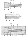
- Figure 3 is a cross-sectional view through a sealed container containing metal powder and a metal insert.
- Figure 4 is a view of metal insert and a predetermined pattern of stop off material on one surface of the metal insert.
- Figure 5 is a cross-sectional view through the sealed container containing metal powder and metal insert as placed in shaped dies prior to consolidation.
- Figure 6 is a view of a consolidated metal powder preform prior to superplastic forming.
- Figure 7 is a view of the consolidated metal powder preform after superplastic forming.
- Figure 8 is a sectional view along line A-A in figure 7.
- A turbofan
gas turbine engine 10, as shown in figure 1, comprises in flow series anintake 12, afan section 14, acompressor section 16, acombustion section 18, aturbine section 20 and anexhaust 22. Thefan section 14 comprises afan rotor 24 carrying a plurality of circumferentially spaced radially outwardly extendingfan blades 26. Thefan blades 26 are arranged in abypass duct 28 defined by afan casing 30, which surrounds thefan rotor 24 andfan blades 26. Thefan casing 30 is secured to a core engine casing 34 by a plurality of circumferentially spaced radially extending fanoutlet guide vanes 32. Thefan rotor 24 andfan blades 26 are arranged to be driven by a turbine (not shown) in theturbine section 20 via a shaft (not shown). Thecompressor section 16 comprises one or more compressors (not shown) arranged to be driven by one or more turbines (not shown) in theturbine section 20 via respective shafts (not shown). - The
fan blade 26 is shown more clearly in figure 2. Thefan blade 26 comprises aroot portion 36 and anaerofoil portion 38. Theroot portion 36 is arranged to locate in aslot 40 in therim 42 of thefan rotor 24, and for example theroot portion 36 may be dovetail shape, or firtree shape, in cross-section and hence thecorresponding slot 40 in therim 42 of thefan rotor 24 is the same shape. Theaerofoil portion 38 has a leadingedge 44, atrailing edge 46 and atip 48 remote from theroot portion 36 and thefan rotor 24. Aconcave pressure surface 50 extends from the leadingedge 44 to thetrailing edge 46 and aconvex suction surface 51 extends from the leadingedge 44 to thetrailing edge 46. - A method of manufacturing a
fan blade 26 by powder metallurgy according to the present invention is shown with reference to figures 3 to 8. The method of manufacturing thefan blade 26 comprises forming acontainer 52. Thecontainer 52 comprises two steel workpieces, steel sheets, 54 and 56. The steel sheets, preferably mild steel sheets, 54 and 56 are cold pressed to a predetermined shape, which is modelled such that a subsequent hot pressing process does not compress, or consolidate, significant amounts of metal powder perpendicular to the loading direction. The peripheries of thesteel sheets container 52 and to define acavity 58 within thecontainer 52. It is preferred that thecontainer 52 is a simple shape. Metal powder, titanium alloy e.g. Ti 6wt% Al, 4wt% V, 60 is supplied into thecavity 58 within thecontainer 52 together with a metal insert, titanium alloy e.g. Ti 6wt% Al, 4wt% V, 62, as shown in figure 3. Themetal insert 62 is provided with a predetermined pattern of stop off material, e.g. yttria, 68, 70 on thesurfaces metal insert 62, as shown in figure 4. Thecontainer 52 is then evacuated and sealed. - The
container 52 is then placed between shapeddies metal powder 60 and to diffusion bond themetal powder 60 to themetal insert 62, except at those positions on thefaces material - The consolidated
metal powder preform 72 is then removed from thecontainer 52 by cutting an edge of thecontainer 52 for example by abrasive water jet cutting, laser cutting etc and then peeling off the remainder of thecontainer 52. Alternatively thecontainer 52 may be removed by dissolving in a suitable acid. - An
aperture 74 is drilled into the consolidated metal powder preform 72 and apipe 76 is inserted into theaperture 74 and sealed to the consolidated metal powder preform 72 connected to the predetermined pattern of stop offmaterial fan blade 26. A pressurised inert gas is supplied through thepipe 76 to inflate the consolidated metal powder preform 72 in the regions where the predetermined pattern of stop offmaterial hollow fan blade 26 with one or moreinternal cavities metal powder preform 72 is heated to a temperature of about 930°C to superplastically form, or hot form, a titanium alloy e.g. Ti 6wt%Al, 4wt% V. - Some final machining of the
hollow fan blade 26 may be required to produce theroot section 36, e.g. to produce a dovetail root or a firtree root, or to accurately produce theleading edge 44 and trailingedge 46. - Although the present invention has been described with reference to manufacturing a fan blade, the present invention may be used to manufacture other components of a gas turbine engine or other articles. For example the present invention may be used to manufacture a compressor blade, a compressor vane or a fan outlet guide vane. The stop off material may be applied to only one surface of the metal insert and the stop off material may be applied to produce any suitable arrangement of cavities, and may if required produce only a single cavity, for example for a fan outlet guide vane.
- The metal powder may be consolidated using hot isostatic pressing by applying heat and supplying pressurised inert gas in a HIPPING vessel. Alternatively the metal powder may be consolidated using hot isostatic pressing by applying heat in an air furnace such that the metal powder is consolidated under atmospheric pressure due to the vacuum in the container. However, residual internal porosity in the consolidated metal powder preform is removed during subsequent hot forming operations.
- The metal powder may be a conventionally produced metal powder or preferably may be a metal powder produced by the chemical or electrochemical processing directly from metal compounds as described in
WO01/62994A W02004/024963A . - The advantage of the present invention is that it is much simpler than the present method of forming a fan blade or fan outlet guide vane. The present invention dispenses with the need to shape two separate metal workpieces, to diffusion bond the metal workpieces together and then to hot form, or superplastically form, at least one of the metal workpieces to form the hollow fan blade or fan outlet guide vane.
Claims (13)
- A method of manufacturing a hollow powder metallurgy comprising the steps of (a) forming a container (52), (b) placing at least one metal insert (62) at a predetermined position within the container (52) and filling the container (52) with metal powder (60), the at least one metal insert (62) having a predetermined pattern of stop off material (68, 70) on at least one surface (64, 65) of the metal insert (62), (c) evacuating the container (52), (d) sealing the container (52), (e) hot pressing the container (52) to consolidate the metal powder (60) into a consolidated metal powder perform (72), (f) removing the container (52) from the consolidated metal powder perform (72), (g) heating the consolidated metal powder preform (72) and supplying a fluid to the predetermined pattern of stop off material (68, 70) to hot form at least a portion of the consolidated metal powder preform (72) to form a hollow metal article (26).
- A method as claimed in claim 1 wherein step (a) comprises forming two workpieces (54, 56) and welding the workpieces (54, 56) together to form the container (52).
- A method as claimed in claim 2 wherein step (a) comprises cold pressing the workpieces (54, 56) to a predetermined shape to form the container (52).
- A method as claimed in any of claims 1 to 3 wherein step (a) comprises forming the container (52) from metal, preferably steel, more preferably mild steel.
- A method as claimed in any of claims 1 to 4 wherein step (e) comprises hot pressing the container (52) in shaped dies.
- A method as claimed in any of claims 1 to 4 wherein step (e) comprises hot isostatic pressing the container (52) in a Hipping vessel.
- A method as claimed in any of claims 1 to 6 wherein step (f) comprises peeling off the container (52) or dissolving the container (52) in an acid.
- A method as claimed in any of claims 1 to 7 wherein the metal powder (60) comprises a titanium alloy.
- A method as claimed in any of claims 1 to 8 wherein the metal insert (62) comprises a titanium alloy.
- A method as claimed in any of claims 1 to 9 wherein the stop off material (68, 70) comprises yttria.
- A method as claimed in any of claims 1 to 10 wherein step (g) comprises supplying a gas to the predetermined pattern of stop off material (68, 70).
- A method as claimed in any of claims 1 to 11 wherein the hollow article (26) is a component of a gas turbine engine (10).
- A method as claimed in claim 12 wherein the hollow article is a compressor blade, a compressor vane, a fan blade (26) or a fan outlet guide vane (32).
Applications Claiming Priority (1)
| Application Number | Priority Date | Filing Date | Title |
|---|---|---|---|
| GBGB0427075.7A GB0427075D0 (en) | 2004-12-10 | 2004-12-10 | A method of manufacturing a metal article by power metallurgy |
Publications (2)
| Publication Number | Publication Date |
|---|---|
| EP1669144A1 EP1669144A1 (en) | 2006-06-14 |
| EP1669144B1 true EP1669144B1 (en) | 2007-06-20 |
Family
ID=34073498
Family Applications (1)
| Application Number | Title | Priority Date | Filing Date |
|---|---|---|---|
| EP05256957A Expired - Lifetime EP1669144B1 (en) | 2004-12-10 | 2005-11-10 | A method of manufacturing a metal article by powder metallurgy |
Country Status (4)
| Country | Link |
|---|---|
| US (1) | US7407622B2 (en) |
| EP (1) | EP1669144B1 (en) |
| DE (1) | DE602005001437T2 (en) |
| GB (1) | GB0427075D0 (en) |
Families Citing this family (26)
| Publication number | Priority date | Publication date | Assignee | Title |
|---|---|---|---|---|
| GB0607228D0 (en) * | 2006-04-11 | 2006-05-17 | Rolls Royce Plc | A method of manufacturing a hollow article |
| JP5429193B2 (en) * | 2009-01-22 | 2014-02-26 | 株式会社Ihi | Manufacturing method of fan blade leading edge reinforcing member |
| GB0922488D0 (en) * | 2009-12-23 | 2010-02-03 | Advanced Interactive Materials | Improvements in or relating to hot isostatic pressing |
| GB201007570D0 (en) * | 2010-05-06 | 2010-06-23 | Rolls Royce Plc | A mould assembly |
| US8392016B2 (en) | 2010-06-25 | 2013-03-05 | LNT PM Inc. | Adaptive method for manufacturing of complicated shape parts by hot isostatic pressing of powder materials with using irreversibly deformable capsules and inserts |
| FR2963294B1 (en) | 2010-07-30 | 2014-10-10 | Faurecia Automotive Ind | ACCESSORY HOLDING DEVICE WITH ADJUSTING MEANS, AND ASSOCIATED ASSEMBLY. |
| US9079245B2 (en) | 2011-08-31 | 2015-07-14 | Pratt & Whitney Canada Corp. | Turbine shroud segment with inter-segment overlap |
| US8784041B2 (en) | 2011-08-31 | 2014-07-22 | Pratt & Whitney Canada Corp. | Turbine shroud segment with integrated seal |
| US8784044B2 (en) | 2011-08-31 | 2014-07-22 | Pratt & Whitney Canada Corp. | Turbine shroud segment |
| US8784037B2 (en) | 2011-08-31 | 2014-07-22 | Pratt & Whitney Canada Corp. | Turbine shroud segment with integrated impingement plate |
| US9028744B2 (en) | 2011-08-31 | 2015-05-12 | Pratt & Whitney Canada Corp. | Manufacturing of turbine shroud segment with internal cooling passages |
| WO2014012187A1 (en) * | 2012-07-20 | 2014-01-23 | Dalhousie University | Die compaction powder metallurgy |
| EP2925477A1 (en) | 2012-11-30 | 2015-10-07 | European Space Agency | Method of manufacturing a metallic component from individual units arranged in a space filling arrangement |
| EP2796230A1 (en) | 2013-04-22 | 2014-10-29 | Gervaux Ltd | Method of manufacturing a metallic component by use of wire winding and hot isostatic pressing |
| GB2517939B (en) | 2013-09-05 | 2016-08-10 | Rolls Royce Plc | A method and apparatus for separating a canister and component |
| BE1022481B1 (en) | 2014-10-28 | 2016-05-02 | Techspace Aero S.A. | DAWN WITH AXIAL TURBOMACHINE COMPRESSOR LATTICE |
| US11117190B2 (en) | 2016-04-07 | 2021-09-14 | Great Lakes Images & Engineering, Llc | Using thin-walled containers in powder metallurgy |
| WO2018091969A1 (en) * | 2016-11-18 | 2018-05-24 | Salvatore Moricca | Controlled hip container collapse for waste treatment |
| US11274569B2 (en) | 2017-12-13 | 2022-03-15 | Pratt & Whitney Canada Corp. | Turbine shroud cooling |
| US10570773B2 (en) | 2017-12-13 | 2020-02-25 | Pratt & Whitney Canada Corp. | Turbine shroud cooling |
| US10533454B2 (en) | 2017-12-13 | 2020-01-14 | Pratt & Whitney Canada Corp. | Turbine shroud cooling |
| US10502093B2 (en) * | 2017-12-13 | 2019-12-10 | Pratt & Whitney Canada Corp. | Turbine shroud cooling |
| GB201811430D0 (en) * | 2018-07-12 | 2018-08-29 | Rolls Royce Plc | Fabricating hollow components |
| US12233461B2 (en) | 2018-10-19 | 2025-02-25 | Rtx Corporation | Powder metallurgy method using a four-wall cylindrical canister |
| CN112008082A (en) * | 2020-07-30 | 2020-12-01 | 中国航发商用航空发动机有限责任公司 | Method for preparing hollow fan blade powder by hot isostatic pressing near-net-shape forming |
| US11365645B2 (en) | 2020-10-07 | 2022-06-21 | Pratt & Whitney Canada Corp. | Turbine shroud cooling |
Family Cites Families (12)
| Publication number | Priority date | Publication date | Assignee | Title |
|---|---|---|---|---|
| CA990106A (en) | 1972-03-27 | 1976-06-01 | Joseph M. Wentzell | Methods and apparatus for consolidating powder |
| GB1400118A (en) * | 1972-11-13 | 1975-07-16 | Crucible Inc | Method for the production of hollow powder metal articles |
| US4142888A (en) * | 1976-06-03 | 1979-03-06 | Kelsey-Hayes Company | Container for hot consolidating powder |
| JPS58141896A (en) | 1982-02-19 | 1983-08-23 | Toyota Motor Corp | Forming method of horizontal hole in powder molding |
| JPS61273298A (en) | 1985-05-28 | 1986-12-03 | Nippon Kokan Kk <Nkk> | Powder molding method |
| US5130084A (en) * | 1990-12-24 | 1992-07-14 | United Technologies Corporation | Powder forging of hollow articles |
| GB2306353B (en) * | 1995-10-28 | 1998-10-07 | Rolls Royce Plc | A method of manufacturing a blade |
| US5960249A (en) * | 1998-03-06 | 1999-09-28 | General Electric Company | Method of forming high-temperature components and components formed thereby |
| JP3702719B2 (en) | 1999-08-12 | 2005-10-05 | セイコーエプソン株式会社 | Screw manufacturing method |
| GB0112876D0 (en) * | 2001-05-26 | 2001-07-18 | Rolls Royce Plc | A method of manufacturing an article |
| GB2400055B (en) * | 2003-03-29 | 2006-01-11 | Rolls Royce Plc | A hollow component with internal damping |
| US7261855B2 (en) * | 2004-03-26 | 2007-08-28 | Igor Troitski | Method and system for manufacturing of complex shape parts from powder materials by hot isostatic pressing with controlled pressure inside the tooling and providing the shape of the part by multi-layer inserts |
-
2004
- 2004-12-10 GB GBGB0427075.7A patent/GB0427075D0/en not_active Ceased
-
2005
- 2005-11-10 EP EP05256957A patent/EP1669144B1/en not_active Expired - Lifetime
- 2005-11-10 DE DE602005001437T patent/DE602005001437T2/en not_active Expired - Lifetime
- 2005-11-15 US US11/273,027 patent/US7407622B2/en active Active
Non-Patent Citations (1)
| Title |
|---|
| None * |
Also Published As
| Publication number | Publication date |
|---|---|
| US20060127265A1 (en) | 2006-06-15 |
| US7407622B2 (en) | 2008-08-05 |
| DE602005001437D1 (en) | 2007-08-02 |
| DE602005001437T2 (en) | 2007-10-31 |
| GB0427075D0 (en) | 2005-01-12 |
| EP1669144A1 (en) | 2006-06-14 |
Similar Documents
| Publication | Publication Date | Title |
|---|---|---|
| US7407622B2 (en) | Method of manufacturing a metal article by powder metallurgy | |
| US7594325B2 (en) | Aerofoil and a method of manufacturing an aerofoil | |
| EP2392423B1 (en) | A method of manufacturing an article by diffusion bonding and superplastic forming | |
| CN105935774B (en) | the process used to make the object | |
| US5609470A (en) | Turbomachine aerofoil with concave surface irregularities | |
| EP2841701B1 (en) | Gas turbine engine airfoil impingement cooling | |
| EP1508400B1 (en) | A method of manufacturing an article by diffusion bonding and superplastic forming | |
| US5323536A (en) | Method of manufacturing an article by superplastic forming and diffusion bonding | |
| EP1260300B1 (en) | A method of manufacturing an article | |
| EP1338353A1 (en) | A method of manufacturing an article by diffusion bonding and superplastic forming | |
| RU2532783C2 (en) | Manufacturing method of system containing many blades installed in platform | |
| US5956561A (en) | Net shaped dies and molds and method for producing the same | |
| US20050142023A1 (en) | Apparatus and a method of manufacturing an article by consolidating powder material | |
| EP1844885B1 (en) | A method of manufacturing a hollow article | |
| EP2340905B1 (en) | A method of manufacturing a component | |
| EP2036650B1 (en) | Joining method | |
| EP1780377A2 (en) | Method for coating a turbine shroud | |
| EP2354450A2 (en) | Rotor wheel capable of carrying multiple blade stages | |
| EP3000546B1 (en) | Method of manufacturing gas turbine engine component from a molybdenum-rich alloy | |
| GB2419835A (en) | Method of diffusion bonding | |
| RU2754943C1 (en) | Method for manufacturing element of running-in seal of turbomachine | |
| EP3187284B1 (en) | Dynamic bonding of powder metallurgy materials | |
| GB2451780A (en) | Manufacturing aerofoil with metal foam core |
Legal Events
| Date | Code | Title | Description |
|---|---|---|---|
| PUAI | Public reference made under article 153(3) epc to a published international application that has entered the european phase |
Free format text: ORIGINAL CODE: 0009012 |
|
| AK | Designated contracting states |
Kind code of ref document: A1 Designated state(s): AT BE BG CH CY CZ DE DK EE ES FI FR GB GR HU IE IS IT LI LT LU LV MC NL PL PT RO SE SI SK TR |
|
| AX | Request for extension of the european patent |
Extension state: AL BA HR MK YU |
|
| 17P | Request for examination filed |
Effective date: 20060602 |
|
| GRAP | Despatch of communication of intention to grant a patent |
Free format text: ORIGINAL CODE: EPIDOSNIGR1 |
|
| AKX | Designation fees paid |
Designated state(s): DE FR GB |
|
| GRAS | Grant fee paid |
Free format text: ORIGINAL CODE: EPIDOSNIGR3 |
|
| GRAA | (expected) grant |
Free format text: ORIGINAL CODE: 0009210 |
|
| AK | Designated contracting states |
Kind code of ref document: B1 Designated state(s): DE FR GB |
|
| REG | Reference to a national code |
Ref country code: GB Ref legal event code: FG4D |
|
| REF | Corresponds to: |
Ref document number: 602005001437 Country of ref document: DE Date of ref document: 20070802 Kind code of ref document: P |
|
| ET | Fr: translation filed | ||
| PLBE | No opposition filed within time limit |
Free format text: ORIGINAL CODE: 0009261 |
|
| STAA | Information on the status of an ep patent application or granted ep patent |
Free format text: STATUS: NO OPPOSITION FILED WITHIN TIME LIMIT |
|
| 26N | No opposition filed |
Effective date: 20080325 |
|
| REG | Reference to a national code |
Ref country code: FR Ref legal event code: PLFP Year of fee payment: 11 |
|
| REG | Reference to a national code |
Ref country code: FR Ref legal event code: PLFP Year of fee payment: 12 |
|
| REG | Reference to a national code |
Ref country code: FR Ref legal event code: PLFP Year of fee payment: 13 |
|
| PGFP | Annual fee paid to national office [announced via postgrant information from national office to epo] |
Ref country code: DE Payment date: 20191127 Year of fee payment: 15 |
|
| PGFP | Annual fee paid to national office [announced via postgrant information from national office to epo] |
Ref country code: FR Payment date: 20191125 Year of fee payment: 15 |
|
| PGFP | Annual fee paid to national office [announced via postgrant information from national office to epo] |
Ref country code: GB Payment date: 20191127 Year of fee payment: 15 |
|
| REG | Reference to a national code |
Ref country code: DE Ref legal event code: R119 Ref document number: 602005001437 Country of ref document: DE |
|
| GBPC | Gb: european patent ceased through non-payment of renewal fee |
Effective date: 20201110 |
|
| PG25 | Lapsed in a contracting state [announced via postgrant information from national office to epo] |
Ref country code: FR Free format text: LAPSE BECAUSE OF NON-PAYMENT OF DUE FEES Effective date: 20201130 |
|
| PG25 | Lapsed in a contracting state [announced via postgrant information from national office to epo] |
Ref country code: DE Free format text: LAPSE BECAUSE OF NON-PAYMENT OF DUE FEES Effective date: 20210601 Ref country code: GB Free format text: LAPSE BECAUSE OF NON-PAYMENT OF DUE FEES Effective date: 20201110 |