EP1669024A1 - Cuff for blood pressure monitor and blood pressure monitor having the same - Google Patents
Cuff for blood pressure monitor and blood pressure monitor having the same Download PDFInfo
- Publication number
- EP1669024A1 EP1669024A1 EP05026652A EP05026652A EP1669024A1 EP 1669024 A1 EP1669024 A1 EP 1669024A1 EP 05026652 A EP05026652 A EP 05026652A EP 05026652 A EP05026652 A EP 05026652A EP 1669024 A1 EP1669024 A1 EP 1669024A1
- Authority
- EP
- European Patent Office
- Prior art keywords
- blood pressure
- cuff
- bag
- pressure monitor
- inflated
- Prior art date
- Legal status (The legal status is an assumption and is not a legal conclusion. Google has not performed a legal analysis and makes no representation as to the accuracy of the status listed.)
- Withdrawn
Links
- 230000036772 blood pressure Effects 0.000 title claims abstract description 147
- 239000002356 single layer Substances 0.000 claims abstract description 19
- 239000012530 fluid Substances 0.000 claims description 29
- 238000004891 communication Methods 0.000 claims description 15
- 239000000463 material Substances 0.000 claims description 13
- 230000003247 decreasing effect Effects 0.000 claims description 9
- 238000005304 joining Methods 0.000 claims description 8
- 150000001336 alkenes Chemical class 0.000 claims description 3
- 229920001577 copolymer Polymers 0.000 claims description 3
- 239000005038 ethylene vinyl acetate Substances 0.000 claims description 3
- JRZJOMJEPLMPRA-UHFFFAOYSA-N olefin Natural products CCCCCCCC=C JRZJOMJEPLMPRA-UHFFFAOYSA-N 0.000 claims description 3
- 239000004814 polyurethane Substances 0.000 claims description 3
- 239000004800 polyvinyl chloride Substances 0.000 claims description 3
- 229920002725 thermoplastic elastomer Polymers 0.000 claims description 3
- DQXBYHZEEUGOBF-UHFFFAOYSA-N but-3-enoic acid;ethene Chemical compound C=C.OC(=O)CC=C DQXBYHZEEUGOBF-UHFFFAOYSA-N 0.000 claims description 2
- 229920001200 poly(ethylene-vinyl acetate) Polymers 0.000 claims description 2
- 229920003225 polyurethane elastomer Polymers 0.000 claims description 2
- 229920000915 polyvinyl chloride Polymers 0.000 claims description 2
- 229920005989 resin Polymers 0.000 abstract description 76
- 239000011347 resin Substances 0.000 abstract description 76
- 238000003825 pressing Methods 0.000 abstract description 16
- 238000002844 melting Methods 0.000 abstract description 12
- 230000008018 melting Effects 0.000 abstract description 12
- 230000009467 reduction Effects 0.000 abstract description 4
- 230000001747 exhibiting effect Effects 0.000 abstract 1
- 210000001367 artery Anatomy 0.000 description 33
- 210000000707 wrist Anatomy 0.000 description 23
- 238000005259 measurement Methods 0.000 description 14
- 238000000034 method Methods 0.000 description 10
- 238000009530 blood pressure measurement Methods 0.000 description 8
- 238000009826 distribution Methods 0.000 description 8
- 230000008569 process Effects 0.000 description 6
- 238000010586 diagram Methods 0.000 description 5
- 230000010355 oscillation Effects 0.000 description 5
- 230000002093 peripheral effect Effects 0.000 description 5
- 230000000694 effects Effects 0.000 description 4
- 230000006870 function Effects 0.000 description 4
- 230000015556 catabolic process Effects 0.000 description 3
- 230000007423 decrease Effects 0.000 description 3
- 238000006731 degradation reaction Methods 0.000 description 3
- 239000004744 fabric Substances 0.000 description 3
- 239000010410 layer Substances 0.000 description 3
- 230000004872 arterial blood pressure Effects 0.000 description 2
- 230000006872 improvement Effects 0.000 description 2
- 238000004519 manufacturing process Methods 0.000 description 2
- 238000004804 winding Methods 0.000 description 2
- 239000004743 Polypropylene Substances 0.000 description 1
- 239000000853 adhesive Substances 0.000 description 1
- 230000001070 adhesive effect Effects 0.000 description 1
- 230000008859 change Effects 0.000 description 1
- 230000006866 deterioration Effects 0.000 description 1
- 230000035487 diastolic blood pressure Effects 0.000 description 1
- 229920001971 elastomer Polymers 0.000 description 1
- 239000000284 extract Substances 0.000 description 1
- 230000002349 favourable effect Effects 0.000 description 1
- 239000007788 liquid Substances 0.000 description 1
- 210000003141 lower extremity Anatomy 0.000 description 1
- 238000000691 measurement method Methods 0.000 description 1
- 238000012544 monitoring process Methods 0.000 description 1
- -1 polypropylene Polymers 0.000 description 1
- 229920001155 polypropylene Polymers 0.000 description 1
- 238000012545 processing Methods 0.000 description 1
- 238000009877 rendering Methods 0.000 description 1
- 230000035488 systolic blood pressure Effects 0.000 description 1
- 210000001364 upper extremity Anatomy 0.000 description 1
Images




Classifications
-
- A—HUMAN NECESSITIES
- A61—MEDICAL OR VETERINARY SCIENCE; HYGIENE
- A61B—DIAGNOSIS; SURGERY; IDENTIFICATION
- A61B5/00—Measuring for diagnostic purposes; Identification of persons
- A61B5/02—Detecting, measuring or recording for evaluating the cardiovascular system, e.g. pulse, heart rate, blood pressure or blood flow
- A61B5/021—Measuring pressure in heart or blood vessels
- A61B5/02141—Details of apparatus construction, e.g. pump units or housings therefor, cuff pressurising systems, arrangements of fluid conduits or circuits
-
- A—HUMAN NECESSITIES
- A61—MEDICAL OR VETERINARY SCIENCE; HYGIENE
- A61B—DIAGNOSIS; SURGERY; IDENTIFICATION
- A61B5/00—Measuring for diagnostic purposes; Identification of persons
- A61B5/02—Detecting, measuring or recording for evaluating the cardiovascular system, e.g. pulse, heart rate, blood pressure or blood flow
-
- A—HUMAN NECESSITIES
- A61—MEDICAL OR VETERINARY SCIENCE; HYGIENE
- A61B—DIAGNOSIS; SURGERY; IDENTIFICATION
- A61B5/00—Measuring for diagnostic purposes; Identification of persons
- A61B5/02—Detecting, measuring or recording for evaluating the cardiovascular system, e.g. pulse, heart rate, blood pressure or blood flow
- A61B5/021—Measuring pressure in heart or blood vessels
- A61B5/022—Measuring pressure in heart or blood vessels by applying pressure to close blood vessels, e.g. against the skin; Ophthalmodynamometers
-
- A—HUMAN NECESSITIES
- A61—MEDICAL OR VETERINARY SCIENCE; HYGIENE
- A61B—DIAGNOSIS; SURGERY; IDENTIFICATION
- A61B5/00—Measuring for diagnostic purposes; Identification of persons
- A61B5/02—Detecting, measuring or recording for evaluating the cardiovascular system, e.g. pulse, heart rate, blood pressure or blood flow
- A61B5/021—Measuring pressure in heart or blood vessels
- A61B5/022—Measuring pressure in heart or blood vessels by applying pressure to close blood vessels, e.g. against the skin; Ophthalmodynamometers
- A61B5/02233—Occluders specially adapted therefor
Definitions
- the present invention relates to a cuff for a blood pressure monitor provided with a fluid bag for avascularization of an artery by pressing a living body, arid a blood pressure monitor having the cuff.
- a cuff provided with a fluid bag for pressing an artery located within a living body is wound around the body surface, and arterial pressure pulse waves caused in the artery by inflation/deflation of the fluid bag are detected to measure the blood pressure value.
- the cuff refers to a band-shaped structure having a bladder, which can be wound around a part of a living body, for use in measurement of arterial pressure of an upper limb, a lower limb or the like by introducing fluid such as gas or liquid into the bladder.
- the cuff represents the concept including the fluid bag as well as members for winding the fluid bag around the living body.
- the cuff wound around and fitted on a wrist or an upper arm is also called an arm band or a manchette.
- the width of the cuff for the blood pressure monitor it is important to ensure that the artery is sufficiently pressed for avascularization.
- a long length in the axial direction of the measurement site covered by the cuff can be guaranteed, which enables sufficient pressing and avascularization of the artery.
- the width of the cuff is narrowed, the length in the axial direction of the measurement site covered by the cuff becomes short, in which case it would be difficult to sufficiently press the artery for avascularization. This will be explained in detail in the following.
- Figs. 12A-12C are conceptual diagrams illustrating avascularization performance in the case where a cuff for a blood pressure monitor of Conventional Example 1 is used to press the artery inside the living body for avascularization.
- Fig. 12A is a schematic cross sectional view in the width direction of the cuff for a blood pressure monitor of Conventional Example 1, showing the state where the cuff is fitted on the living body.
- Fig. 12B is a schematic cross sectional view showing the state where the artery is pressed for avascularization using the cuff for a blood pressure monitor of Conventional Example 1.
- Fig. 12C shows pressure distribution over the surface of the living body when pressed with the cuff for a blood pressure monitor of Conventional Example 1. In Figs. 12A and 12B, the cover body covering the air bag is not shown.
- the cuff 130D for a blood pressure monitor of Conventional Example 1 includes an air bag 150D formed by laying two resin sheets 151 and 152 one on the other and melting and bonding their rims, and a curled elastic member 160 identified as an elastic member that is attached to an outer peripheral surface of air bag 150D using a double-faced tape 171 identified as an attaching member.
- Air bag 150D has an inflated/deflated space 157 therein, and has a bonded portion 156 on each end in the width direction that is formed by the above-described melting and bonding. In the fitted state of the cuff, air bag 150D is located between the surface of living body 300 and curled elastic member 160.
- the width of air bag 150D is represented as L1.
- air bag 150D When a pressurized air is introduced into inflated/deflated space 157 to inflate air bag 150D, air bag 150D increases in size in the thickness direction, as shown in Fig. 12B, and its working face 158 pressing living body 300 expands in a balloon shape. With curled elastic member 160 secured, inflation of air bag 150D outwards, i.e., in the opposite direction from living body 300 is restricted, and air bag 150D is inflated only on the side of living body 300. As such, living body 300 is pressed by air bag 150D, and the artery 301 located under the skin of living body 300 is pressed for avascularization.
- artery occluded distance L2
- a pressure P2 within artery 301 on its central side represents a blood pressure value.
- a change of pressure P1 within air bag 150D is read as pressure P2 on the central side within artery 301, to calculate the blood pressure value.
- air bag 150D With the configuration of air bag 150D arranged inside cuff 130D for a blood pressure monitor of Conventional Example 1, however, air bag 150D is inflated in the balloon shape, making it difficult to sufficiently guarantee artery occluded distance L2 with respect to width L1 of air bag 150D. This causes degradation of accuracy in measurement, which problem is particularly noticeable when width L1 of cuff 130D for a blood pressure monitor is decreased. Such degradation of measurement accuracy due to deterioration of avascularization performance poses a very serious problem.
- a cuff for a blood pressure monitor disclosed in Japanese Patent Laying-Open No. 02-107226 and a cuff for a blood pressure monitor disclosed in Japanese Patent Laying-Open No. 2001-224558, for example, are known as those directed to prevent degradation of avascularization performance in association with a decreased cuff width.
- an air bag identified as a fluid bag arranged inside the cuff is provided with a gusset at each end in the width direction. When the air bag is inflated, the gussets expand to make the air bag inflated more uniformly in the width direction.
- Figs. 13A-13C are conceptual diagrams illustrating avascularization performance when using the cuff for a blood pressure monitor of Conventional Example 2 to press the artery inside the living body for avascularization.
- Fig. 13A is a schematic cross sectional view in the width direction of the cuff for a blood pressure monitor of Conventional Example 2, showing the state where the cuff is fitted on the living body.
- Fig. 13B is a schematic cross sectional view showing the state where the artery is pressed for avascularization using the cuff for a blood pressure monitor of Conventional Example 2.
- Fig. 13C shows pressure distribution over the surface of the living body when pressed with the cuff for a blood pressure monitor of Conventional Example 2. In Figs. 13A and 13B, the cover body covering the air bag is not shown.
- the cuff 130E for a blood pressure monitor of Conventional Example 2 includes an air bag 150E and a curled elastic member 160.
- Air bag 150E has a bag member formed by laying two resin sheets 151 and 152 one on the other and melting and bonding their rims, and another bag member formed by laying two resin sheets 153 and 154 one on the other and melting and bonding their rims, which bag members are laid one on the other and melted and bonded together to form air bag 150E.
- Curled elastic member 160 identified as an elastic member is attached to an outer periphery surface of air bag 150E using a double-faced tape 171 as an attaching member.
- Air bag 150E has two layers of inflated/deflated spaces 157a, 157b therein, which are in communication with each other via a communication hole 159. Bonded portions 156a1, 156a2, formed by the above-described melting and bonding, are located at each end in the width direction of air bag 150E. In the fitted state of the cuff, air bag 150E is arranged between the surface of living body 300 and curled elastic member 160.
- air bag 150E When a pressurized air is introduced into inflated/deflated spaces 157a, 157b to inflate air bag 150E, air bag 150E increases in size in the thickness direction, as shown in Fig. 13B. Since the gussets are provided at the respective ends in the width direction of air bag 150E, they expand in the thickness direction of air bag 150E, whereby a working face 158 of air bag 150E pressing living body 300 expands approximately flatly. As such, the both ends in the width direction of air bag 150E and their vicinities expand similarly to the central portion in the width direction of air bag 150E, ensuring more uniform pressing of artery 301 under the skin of living body 300.
- air bag 150E contained in cuff 130E for a blood pressure monitor of Conventional Example 2 is suitable for accurate measurement of the blood pressure value, it requires a large number of resin sheets, and also requires joining of the resin sheets in several steps. As such, the production is complicated, and the cost is high.
- An object of the present invention is to provide a cuff for a blood pressure monitor that can be fabricated with ease and at low cost, that has favorable pressing performance and avascularization performance, and that is suitable for reduction of a cuff width, and to provide a blood pressure monitor provided with the cuff.
- a cuff for a blood pressure monitor has a fluid bag inflated and deflated as a fluid comes in and out, which increases in size in a thickness direction when inflated and decreases in size in the thickness direction when deflated.
- the fluid bag includes a first bag member located on an outer side in the thickness direction in the state where the cuff for a blood pressure monitor is fitted on a living body and having a first inflated/deflated space therein, and a second bag member located on an inner side in the thickness direction in the state where the cuff for a blood pressure monitor is fitted on the living body and having a second inflated/deflated space therein.
- the second bag member is formed by laying a single-layer sheet-shaped member on a surface of the first bag member on the living body side and joining its rim to the living body-side surface. A joined portion of the first bag member with the single-layer sheet-shaped member is positioned inner than each end in a width direction of the first inflated/deflated space.
- the single-layer sheet-shaped member constituting a part of the second bag member expands with the joined portion provided inner than each end in the width direction of the first inflated/deflated space as a base point. This ensures sufficient inflation of the fluid bag in the thickness direction.
- the single-layer sheet-shaped member constituting a part of the second bag member is more elastic than a member forming the living body-side surface of the first bag member.
- the single-layer sheet-shaped member constituting a part of the second bag member is allowed to inflate more flatly in the width direction of the fluid bag, so that the artery occluded distance of still longer length can be guaranteed, which leads to accurate measurement of the blood pressure value.
- a material of the single-layer sheet-shaped member constituting a part of the second bag member is soft polyvinyl chloride, copolymer of ethylene-vinyl acetate, polyurethane, or thermoplastic elastomer olefin.
- the fluid bag becomes superior in elasticity.
- the single-layer sheet-shaped member constituting a part of the second bag member and a member forming the living body-side surface of the first bag member are made of a same material.
- first bag member and the second bag member are formed using the sheet-shaped members of the same material, it is possible to join them by melting and bonding, which allows fabrication of the cuff for a blood pressure monitor of high performance at low cost.
- the single-layer sheet-shaped member constituting a part of the second bag member has a thickness smaller than a thickness of a member forming the living body-side surface of the first bag member.
- the first bag member is formed by laying a plurality of sheet-shaped members one on another and joining their rims together.
- the first inflated/deflated space and the second inflated/deflated space are in communication with each other.
- a blood pressure monitor includes: one of the cuffs for a blood pressure monitor described above; an inflating/deflating portion for inflating and deflating the fluid bag; a pressure detecting portion for detecting a pressure within the fluid bag; and a blood pressure value calculating portion for calculating a blood pressure value based on pressure information detected by the pressure detecting portion.
- the present invention it is possible to fabricate a cuff for a blood pressure monitor having high pressing performance and high avascularization performance, as well as a blood pressure monitor having the cuff, with ease and at low cost. Accordingly, the cuff for a blood pressure monitor suitable for decreasing the cuff width, and the blood pressure monitor provided with the same, can be obtained.
- Fig. 1 is a perspective view of a blood pressure monitor according to the present embodiment.
- the blood pressure monitor 100 of the present embodiment includes a main body 110 and a cuff 130.
- a display portion 111 and a manipulation portion 112 are arranged on the surface of main body 110.
- Cuff 130 is attached to main body 110.
- Fig. 2 is a vertical cross sectional view showing an inner structure of the cuff for the blood pressure monitor shown in Fig. 1.
- cuff 130 for the blood pressure monitor of the present embodiment primarily includes a cover member 140 of a bag shape that is made of cloth or the like, an air bag 150 identified as a fluid bag that is arranged inside cover member 140, and a curled elastic member 160 that is arranged inside cover member 140 on an outer side of air bag 150 in the fitted state of the cuff.
- Curled elastic member 160 is elastic and curved to temporarily mount the cuff on the wrist. Cover member 140, air bag 150 and curled elastic member 160 extend with their longitudinal direction corresponding to the winding direction of cuff 130.
- Cover member 140 has an inner cover 142 made of cloth or the like superior in elasticity and positioned on the inner side in the fitted state, and an outer cover 141 made of cloth or the like inferior in elasticity and positioned on the outer side than inner cover 142.
- Inner cover 142 and outer cover 141 are laid one on the other and their rims are sewn up to form a bag shape.
- a velcro fastener 165 is provided on the inner peripheral surface.
- a velcro fastener 166 for engagement with velcro fastener 165 is attached to the outer peripheral surface.
- Velcro fasteners 165, 166 are members for securing blood pressure monitor 100 on the measurement site of the wrist in a stable manner when cuff 130 is mounted on the wrist.
- Air bag 150 is made of a member of bag shape that is formed using resin sheets identified as sheet-shaped members, and has an inflated/deflated space 157 therein. An inner peripheral surface of air bag 150 serves as a working face 158 for pressing the wrist. Inflated/deflated space 157 is connected via a tube 120 to an air system 121 for blood pressure measurement of main body 110, which will be described later (see Fig. 3). The detailed structure of air bag 150 will be described later.
- any material can be used as long as it exhibits excellent elasticity and prevents leakage of the air from inflated/deflated space 157 after melting and bonding.
- optimal materials for the resin sheets include copolymer of ethylene-vinyl acetate (EVA), soft polyvinyl chloride (PVC), polyurethane (PU), thermoplastic elastomer olefin (TPE-O), crude rubber, and the like.
- curled elastic member 160 On the outer side of air bag 150, curled elastic member 160 identified as an elastic member is arranged, which is wound in an annular shape and elastically deformable in a radial direction. Curled elastic member 160 is attached to the outer surface of the outer wall portion of air bag 150 using an attaching member such as a double-faced tape (not shown). Curled elastic member 160 is configured to maintain its own annular shape, and serves to fit air bag 150 exactly on the living body in the mounted state of the cuff. Curled elastic member 160 is made of a resin member of polypropylene or the like, so as to exert sufficient elastic force.
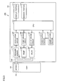
- Fig. 3 is a block diagram showing a configuration of the blood pressure monitor according to the present embodiment.
- main body 110 includes an air system 121 for blood pressure measurement for supplying and evacuating the air to and from air bag 150 via a tube 120, and an oscillation circuit 125, a pump driving circuit 126 and a valve driving circuit 127 which are provided in association with air system 121 for blood pressure measurement.
- These components function as an inflating/deflating portion for inflating and deflating air bag 150.
- Main body 110 further includes a CPU (Central Processing Unit) 113 for controlling and monitoring the respective portions in a centralized manner, a memory portion 114 for storing a program for causing CPU 113 to conduct a prescribed operation and various information including blood pressure values measured, a display portion 111 for displaying the information including a blood pressure measurement result, a manipulation portion 112 manipulated for inputting various instructions for measurement, and a power supply portion 115 for supplying electric power to CPU 113 by an instruction of power ON from manipulation portion 112.
- CPU 113 serves as a blood pressure value calculating portion for calculating a blood pressure value.
- Air system 121 for blood pressure measurement has a pressure sensor 122 having an output value changed in accordance with the pressure within air bag 150 (hereinafter, referred to as "cuff pressure"), a pump 123 for supplying the air to air bag 150, and a valve 124 that is opened or closed to evacuate the air from or seal the air in air bag 150.
- Pressure sensor 122 serves as a pressure detecting portion for detecting the cuff pressure.
- Oscillation circuit 125 outputs to CPU 113 a signal of oscillation frequency corresponding to the output value of pressure sensor 122.
- Pump driving circuit 126 controls driving of pump 123 based on a control signal supplied from CPU 113.
- Valve driving circuit 127 controls opening/closing of valve 124 based on a control signal supplied from CPU 113.
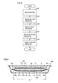
- Fig. 4 is a flowchart illustrating the process flow of blood pressure measurement by the blood pressure monitor according to the present embodiment.
- the program according to this flowchart is prestored in memory portion 114, and the blood pressure measuring process is carried out as CPU 113 reads out this program from memory portion 114 and executes the same.
- blood pressure monitor 100 is initialized (step S101).
- CPU 113 starts driving of pump 123 to gradually increase the cuff pressure of air bag 150 (step S102).
- CPU 113 stops pump 123, and gradually opens the closed valve 124 to evacuate the air from air bag 150, so as to gradually reduce the cuff pressure (step S103).
- the blood pressure is measured during the process of gradually decreasing the cuff pressure.
- CPU 113 calculates the blood pressure (systolic blood pressure, diastolic blood pressure) in a known manner (step S104). Specifically, during the process where the cuff pressure is gradually decreased, CPU 113 extracts pulse wave information based on the oscillation frequency obtained from oscillation circuit 125. It then calculates the blood pressure value from the pulse wave information extracted. The blood pressure value obtained in step S 104 is displayed on display portion 111 (step S105).
- the measurement method described above is based on a so-called “decreasing-pressure measurement method” where the pulse waves are detected while the air bag is being decreased in pressure
- Blood pressure monitor 110 and cuff 130 for a blood pressure monitor of the present embodiment are characterized by the structure of air bag 150 arranged inside cuff 130 for a blood pressure monitor.
- air bag 150 arranged inside cuff 130 for a blood pressure monitor.
- Fig. 5 is a schematic cross sectional view of a cuff for a blood pressure monitor according to Example 1 based on the present embodiment, taken along the line V-V shown in Fig. 2.
- Fig. 6 is an enlarged view of a region VI shown in Fig. 5.
- the cuff 130A for a blood pressure monitor of the present example includes an air bag 150A identified as a fluid bag and a curled elastic member 160 identified as an elastic member, which are arranged inside a cover member 140 formed of an inner cover 142 and an outer cover 141. Curled elastic member 160 is attached to an outer peripheral surface of air bag 150A via a double-faced tape 171 identified as an attaching member.
- Air bag 150A is formed into a bag shape using three resin sheets 151, 152 and 153.
- Air bag 150A includes a first bag member positioned on the outer side in the thickness direction of air bag 150A in the state where cuff 130A for a blood pressure monitor is mounted on the wrist, and a second bag member positioned on the inner side in the thickness direction of air bag 150A in the state where cuff 130A is mounted on the wrist.
- the first bag member is formed of two resin sheets 151 and 152, and has a first inflated/deflated space 157a therein.
- the second bag member is formed of two resin sheets 152 and 153, and has a second inflated/deflated space 157b therein.
- First and second inflated/deflated spaces 157a and 157b are in communication with each other via a communication hole 159 provided at a prescribed position of resin sheet 152.
- Resin sheet 153 constitutes an inner wall portion of air bag 150A.
- Resin sheet 151 constitutes an outer wall portion of air bag 150A.
- a surface on the wrist side of the inner wall portion of air bag 150A functions as a working face 158 for pressing the wrist.
- Air bag 150A of the above-described configuration is fabricated, e.g., in the following manner. Two resin sheets 151, 152 of an approximately rectangular shape in two dimensions are laid one on the other and their rims are melted and bonded to form the first bag member. Further, resin sheet 153 of an approximately rectangular shape but slightly narrower in width is laid on the first bag member, and the rim of resin sheet 153 is melted and bonded to a prescribed position on the outer surface of resin sheet 152 of the first bag member, to thereby form air bag 150A. Thus, compared to air bag 150E (see Figs.
- the air bag having two-layers of stacked inflated/deflated spaces can be formed using a smaller number of resin sheets. With the decrease in number of resin sheets, the number of melted and bonded portions also decreases. Accordingly, air bag 150A of the present example can be fabricated more easily and less expensively than air bag 150E of Conventional Example 2.
- Two resin sheets 151 and 152 forming the first bag member having first inflated/deflated space 157a therein are joined together by stacking them and melting and boding their rims.
- a bonded portion 156a is located at each end in the width direction of air bag 150A.
- a bonded portion 156b that is the joined portion of two resin sheets 152 and 153 forming the second bag member having second inflated/deflated space 157b therein is provided inner than each end in the width direction of first inflated/deflated space 157a formed inside the first bag member.
- bonded portion 156b of resin sheets 152 and 153 is positioned closer to the central portion than each end of a region W (see Fig. 5) where first inflated/deflated space 157a is located.
- bonded portion 156b of resin sheets 152 and 153 is located still inner than the inner end of bonded portion 156a of resin sheets 151 and 152.
- bonded portion 156a and bonded portion 156b are spaced apart from each other by a prescribed distance.
- the prescribed distance more than about 5% and less than about 25% of the width (shown by W in Fig. 5) of inflated/deflated space 157a of the first bag member is suitable.
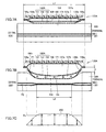
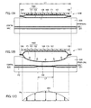
- Figs. 7A-7C are conceptual diagrams illustrating avascularization performance in the case where the cuff for a blood pressure monitor of the present example is used to press the artery inside the living body for avascularization.
- Fig. 7A is a schematic cross sectional view in the width direction of the cuff for a blood pressure monitor of the present example, showing the state where the cuff is fitted on the living body.
- Fig. 7B is a schematic cross sectional view showing the state where the artery is pressed for avascularization using the cuff for a blood pressure monitor of the present example.
- Fig. 7C shows pressure distribution on the surface of the living body when pressed with the cuff for a blood pressure monitor of the present example. In Figs. 7A and 7B, the cover body covering the air bag is not shown.
- air bag 150A is arranged between the surface of living body 300 and curled elastic member 160.
- the first bag member of air bag 150A is located on the outer side in the direction crossing the axial direction of living body 300, and the second bag member is located on the inner side.
- bonded portion 156b of the first bag member with the second bag member is located inner than each end in the width direction of inflated/deflated space 157a formed in the first bag member by a prescribed distance.
- resin sheet 153 forming a part of the second bag member expands with this bonded portion 156b as a base point.
- stroke t of bonded portion 156b toward the living body occurs along with inflation of the first bag member as shown in Fig. 7B, and thus, compared to air bag 150D (see Figs. 12A-12C) contained in cuff 130D for a blood pressure monitor of Conventional Example 1, a further increase in size of the air bag in the direction of the living body is allowed upon inflation of the second bag member.
- resin sheet 153 forming a part of the second bag member is superior in elasticity to resin sheets 151, 152 forming the first bag member.
- the pressurized air is distributed sufficiently to reach the both ends in the width direction of the second bag member, which makes it possible to press living body 300 more flatly.
- resin sheet 153 forming a part of the second bag member more elastic than resin sheets 151 and 152 forming the first bag member
- three resin sheets 151, 152 and 153 may be made of the same material and resin sheet 153 forming a part of the second bag member may be made thinner than other resin sheets 151 and 152.
- resin sheet 153 forming a part of the second bag member may be formed of a material that is more elastic than the material of other resin sheets 151 and 152.
- a cuff for a blood pressure monitor implementing high pressing performance and high avascularization performance with a simple configuration.
- This cuff for a blood pressure monitor is suitable for reduction of the cuff width. Accordingly, a blood pressure monitor of high performance and of which fitting operation is simple can be provided.
- Fig. 8 is a schematic cross sectional view of a cuff for a blood pressure monitor according to Example 2 based on the present embodiment.
- Fig. 9 is an enlarged view of a region IX shown in Fig. 8.
- the portions different from those of cuff 130A for a blood pressure monitor of Example 1 will be described, while description of the similar portions will not be repeated.
- the air bag 150B contained in the cuff 130B for a blood pressure monitor according to the present example has a configuration where a single-layer resin sheet 154 is additionally provided on the outer surface on the living body side of air bag 150A contained in cuff 130A for a blood pressure monitor of Example 1 described above.
- Air bag 150B includes a first bag member located on the outer side in the thickness direction of air bag 150B in the state where cuff 130B for a blood pressure monitor is mounted on the wrist, and a second bag member located on the inner side in the thickness direction of air bag 150B in the state where cuff 130B is mounted on the wrist.
- the first bag member is formed of three resin sheets 151, 152 and 153, and has first inflated/deflated spaces 157a, 157b therein. First inflated/deflated spaces 157a and 157b partitioned by resin sheet 152 are in communication with each other via a communication hole 159a formed at a prescribed position of resin sheet 152.
- the second bag member is formed of two resin sheets 153 and 154, and has a second inflated/deflated space 157c therein.
- First inflated/deflated space 157b located on the living body side is in communication with second inflated/deflated space 157c via a communication hole 159b provided at a prescribed position of resin sheet 153.
- Resin sheet 154 constitutes an inner wall portion of air bag 150B.
- Resin sheet 151 constitutes an outer wall portion of air bag 150B.
- a surface on the wrist side of the inner wall portion of air bag 150B functions as a working face 158 for pressing the wrist.
- Air bag 150B having the above-described configuration is fabricated, e.g., in the following manner.
- a resin sheet 154 of an approximately rectangular shape in two dimensions and having a narrow width is laid on air bag 150A shown in Example 1 above, and the rim of resin sheet 154 is melted and bonded to a prescribed position on the outer surface of resin sheet 153 of the first bag member.
- a bonded portion 156c that is a joined portion of two resin sheets 153 and 154 forming the second bag member and having second inflated/deflated space 157c therein is located inner than each end in the width direction of first inflated/deflated spaces 157a and 157b formed inside the first bag member. More specifically, bonded portion 156c of resin sheets 153 and 154 is provided closer to the central portion than each end of a region W1 (see Fig. 8) where first inflated/deflated space 157a is located, and is provided still closer to the central portion than each end of a region W2 (see Fig.
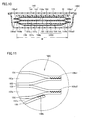
- Fig. 10 is a schematic cross sectional view of a cuff for a blood pressure monitor according to Example 3 based on the present embodiment.
- Fig. 11 is an enlarged view of a region XI shown in Fig 10. In the following, the portions different from those of Example 1 above will be explained, while description of the similar portions will not be repeated.
- an air bag 150C contained in a cuff 130C for a blood pressure monitor of the present example is characterized in that the first bag member of air bag 150A contained in 130A for a blood pressure monitor of Example 1 is formed using four resin sheets to have two layers of inflated/deflated spaces.
- Air bag 150C includes a first bag member located on the outer side in the thickness direction of air bag 150C in the state where cuff 130C for a blood pressure monitor is mounted on the wrist, and a second bag member positioned on the inner side in the thickness direction of air bag 150C when cuff 130C is mounted on the wrist.
- the first bag member is formed of four resin sheets 151, 152, 153 and 154, and has first inflated/deflated spaces 157a and 157b therein. First inflated/deflated spaces partitioned by resin sheets 152 and 153 are in communication with each other via a communication hole 159a formed at a prescribed position of resin sheets 152 and 153.
- the second bag member is formed of two resin sheets 154 and 155, and has a second inflated/deflated space 157c therein.
- First inflated/deflated space 157b located on the living body side is in communication with second inflated/deflated space 157c via a communication hole 159b provided at a prescribed position of resin sheet 154.
- Resin sheet 155 constitutes an inner wall portion of air bag 150C
- resin sheet 151 constitutes an outer wall portion of air bag 150C
- a surface on the wrist side of the inner wall portion of air bag 150C functions as a working face 158 for pressing the wrist.
- Air bag 150C having the above-described configuration is fabricated, e.g., in the following manner. Two resin sheets 151 and 152 of an approximately rectangular shape in two dimensions are laid one on the other and their rims are melted and bonded to form a bag member, and two resin sheets 153 and 154 of an approximately rectangular shape in two dimensions are laid one on the other and their rims are melted and bonded to form another bag member. The bag members are then laid one on the other and melted and bonded to form the first bag member. Resin sheet 155 of an approximately rectangular shape in two dimensions but narrower in width is laid on the first bag member, and the rim of resin sheet 155 is melted and bonded to a prescribed position of the outer surface of resin sheet 154 of the first bag member. Air bag 150C is thus fabricated.
- a bonded portion 156b that is a joined portion of two resin sheets 154 and 155 forming the second bag member having second inflated/deflated space 157c therein is provided inner than each end in the width direction of first inflated/deflated spaces 157a and 157b formed inside the first bag member. More specifically, bonded portion 156b of resin sheets 154 and 155 is provided closer to the central portion than each end of a region W (see Fig. 10) where first inflated/deflated spaces 157a, 157b are located. This enables resin sheet 155 forming a part of the second bag member to expand with this bonded portion 156b as a base point, and accordingly, the effect equal to the effect explained in Example 1 above can be obtained.
- Examples 1-3 based on the above embodiment, explanation was made to join the resin sheets by melting and bonding. Joining however is not necessarily restricted to melting and bonding; they may of course be adhered using an adhesive. Further, in Examples 1-3 above, the case of laying a plurality of resin sheets one on another and melting and bonding them to form the first bag member has been explained by way of example. The first bag member however does not necessarily have to be formed using a plurality of resin sheets.
- the air bag may be formed using a single sheet in a cylindrical shape, and the present invention is applicable to such a case as well.
- the double-faced tape to attach the air bag to the curled elastic member has been explained by way of example. However, they do not necessarily have to be secured by adhesion or the like. They may be secured using another method, or they may be left completely unfixed to each other.
- the present invention is applicable to a cuff of a blood pressure monitor of any type including an upper arm type and a finger type.
Landscapes
- Health & Medical Sciences (AREA)
- Life Sciences & Earth Sciences (AREA)
- Cardiology (AREA)
- Vascular Medicine (AREA)
- Biomedical Technology (AREA)
- Molecular Biology (AREA)
- Physiology (AREA)
- Biophysics (AREA)
- Pathology (AREA)
- Engineering & Computer Science (AREA)
- Veterinary Medicine (AREA)
- Heart & Thoracic Surgery (AREA)
- Medical Informatics (AREA)
- Physics & Mathematics (AREA)
- Surgery (AREA)
- Animal Behavior & Ethology (AREA)
- General Health & Medical Sciences (AREA)
- Public Health (AREA)
- Ophthalmology & Optometry (AREA)
- Dentistry (AREA)
- Measuring Pulse, Heart Rate, Blood Pressure Or Blood Flow (AREA)
Abstract
Description
- The present invention relates to a cuff for a blood pressure monitor provided with a fluid bag for avascularization of an artery by pressing a living body, arid a blood pressure monitor having the cuff.
- To measure a blood pressure value, generally, a cuff provided with a fluid bag for pressing an artery located within a living body is wound around the body surface, and arterial pressure pulse waves caused in the artery by inflation/deflation of the fluid bag are detected to measure the blood pressure value. Here, the cuff refers to a band-shaped structure having a bladder, which can be wound around a part of a living body, for use in measurement of arterial pressure of an upper limb, a lower limb or the like by introducing fluid such as gas or liquid into the bladder. Thus, the cuff represents the concept including the fluid bag as well as members for winding the fluid bag around the living body. Particularly, the cuff wound around and fitted on a wrist or an upper arm is also called an arm band or a manchette.
- Recently, blood pressure monitors are often used not only in medical treatment facilities such as hospitals but also in the households as an apparatus for checking the physical conditions day by day. As such, there are strong demands for improvement in handling of the blood pressure monitors, particularly for ease in fitting operation. To this end, downsizing of the cuff has been attempted. To downsize the cuff, it is necessary to narrow the cuff particularly in the width direction (i.e., direction parallel to the axial direction of the measurement site (e.g., wrist, upper arm or the like) to which the cuff is applied), for achievement of excellent fitting even for a person having an upper arm of short length, or for improved fitting to a wrist.
- To narrow the width of the cuff for the blood pressure monitor, it is important to ensure that the artery is sufficiently pressed for avascularization. In the case of using a cuff for a blood pressure monitor having a large width, a long length in the axial direction of the measurement site covered by the cuff can be guaranteed, which enables sufficient pressing and avascularization of the artery. However, if the width of the cuff is narrowed, the length in the axial direction of the measurement site covered by the cuff becomes short, in which case it would be difficult to sufficiently press the artery for avascularization. This will be explained in detail in the following.
- Figs. 12A-12C are conceptual diagrams illustrating avascularization performance in the case where a cuff for a blood pressure monitor of Conventional Example 1 is used to press the artery inside the living body for avascularization. Fig. 12A is a schematic cross sectional view in the width direction of the cuff for a blood pressure monitor of Conventional Example 1, showing the state where the cuff is fitted on the living body. Fig. 12B is a schematic cross sectional view showing the state where the artery is pressed for avascularization using the cuff for a blood pressure monitor of Conventional Example 1. Fig. 12C shows pressure distribution over the surface of the living body when pressed with the cuff for a blood pressure monitor of Conventional Example 1. In Figs. 12A and 12B, the cover body covering the air bag is not shown.
- As shown in Fig. 12A, the
cuff 130D for a blood pressure monitor of Conventional Example 1 includes anair bag 150D formed by laying tworesin sheets elastic member 160 identified as an elastic member that is attached to an outer peripheral surface ofair bag 150D using a double-faced tape 171 identified as an attaching member.Air bag 150D has an inflated/deflatedspace 157 therein, and has a bondedportion 156 on each end in the width direction that is formed by the above-described melting and bonding. In the fitted state of the cuff,air bag 150D is located between the surface ofliving body 300 and curledelastic member 160. Herein, the width ofair bag 150D is represented as L1. - When a pressurized air is introduced into inflated/deflated
space 157 to inflateair bag 150D,air bag 150D increases in size in the thickness direction, as shown in Fig. 12B, and its workingface 158 pressingliving body 300 expands in a balloon shape. With curledelastic member 160 secured, inflation ofair bag 150D outwards, i.e., in the opposite direction fromliving body 300 is restricted, andair bag 150D is inflated only on the side ofliving body 300. As such,living body 300 is pressed byair bag 150D, and theartery 301 located under the skin ofliving body 300 is pressed for avascularization. - In order to completely occlude
artery 301, it is required that the pressure applied byair bag 150D to the surface ofliving body 300 is not less than a prescribed level. That is, when the pressure on the surface ofliving body 300 required to completely occludeartery 301 is represented as PA,artery 301 is occluded only in the region where thepressure distribution curve 200 on the body surface exceeds pressure PA, as shown in Fig. 12C. Herein, the length or distance of a portion ofartery 301 in its extending direction occluded by inflation ofair bag 150D (hereinafter, referred to as "artery occluded distance") is represented as L2. - In the state where
artery 301 is pressed for avascularization, a pressure P2 withinartery 301 on its central side represents a blood pressure value. In the blood pressure monitor, a change of pressure P1 withinair bag 150D is read as pressure P2 on the central side withinartery 301, to calculate the blood pressure value. Thus, for accurate measurement of the blood pressure value, it is necessary to minimize the difference between pressure P2 withinartery 301 and pressure P1 withinair bag 150D to the greatest possible extent, for which it is critical to secure a sufficiently long length of artery occluded distance L2 described above. - With the configuration of
air bag 150D arranged insidecuff 130D for a blood pressure monitor of Conventional Example 1, however,air bag 150D is inflated in the balloon shape, making it difficult to sufficiently guarantee artery occluded distance L2 with respect to width L1 ofair bag 150D. This causes degradation of accuracy in measurement, which problem is particularly noticeable when width L1 ofcuff 130D for a blood pressure monitor is decreased. Such degradation of measurement accuracy due to deterioration of avascularization performance poses a very serious problem. - A cuff for a blood pressure monitor disclosed in Japanese Patent Laying-Open No. 02-107226 and a cuff for a blood pressure monitor disclosed in Japanese Patent Laying-Open No. 2001-224558, for example, are known as those directed to prevent degradation of avascularization performance in association with a decreased cuff width. In each of the cuffs for a blood pressure monitor disclosed in these publications, an air bag identified as a fluid bag arranged inside the cuff is provided with a gusset at each end in the width direction. When the air bag is inflated, the gussets expand to make the air bag inflated more uniformly in the width direction. Particularly in the case where the configuration disclosed in Japanese Patent Laying-Open No. 2001-224558 is employed, artery occluded distance L2 of a very long length can be guaranteed with respect to the width of the air bag, thereby rendering this technique essential for reduction of the cuff width. Hereinafter, the cuff for a blood pressure monitor disclosed in Japanese Patent Laying-Open No. 2001-224558 will be explained as Conventional Example 2.
- Figs. 13A-13C are conceptual diagrams illustrating avascularization performance when using the cuff for a blood pressure monitor of Conventional Example 2 to press the artery inside the living body for avascularization. Fig. 13A is a schematic cross sectional view in the width direction of the cuff for a blood pressure monitor of Conventional Example 2, showing the state where the cuff is fitted on the living body. Fig. 13B is a schematic cross sectional view showing the state where the artery is pressed for avascularization using the cuff for a blood pressure monitor of Conventional Example 2. Fig. 13C shows pressure distribution over the surface of the living body when pressed with the cuff for a blood pressure monitor of Conventional Example 2. In Figs. 13A and 13B, the cover body covering the air bag is not shown.
- As shown in Fig. 13A, the
cuff 130E for a blood pressure monitor of Conventional Example 2 includes anair bag 150E and a curledelastic member 160.Air bag 150E has a bag member formed by laying tworesin sheets resin sheets air bag 150E. Curledelastic member 160 identified as an elastic member is attached to an outer periphery surface ofair bag 150E using a double-faced tape 171 as an attaching member.Air bag 150E has two layers of inflated/deflatedspaces communication hole 159. Bonded portions 156a1, 156a2, formed by the above-described melting and bonding, are located at each end in the width direction ofair bag 150E. In the fitted state of the cuff,air bag 150E is arranged between the surface of livingbody 300 and curledelastic member 160. - When a pressurized air is introduced into inflated/deflated
spaces air bag 150E,air bag 150E increases in size in the thickness direction, as shown in Fig. 13B. Since the gussets are provided at the respective ends in the width direction ofair bag 150E, they expand in the thickness direction ofair bag 150E, whereby a workingface 158 ofair bag 150E pressing livingbody 300 expands approximately flatly. As such, the both ends in the width direction ofair bag 150E and their vicinities expand similarly to the central portion in the width direction ofair bag 150E, ensuring more uniform pressing ofartery 301 under the skin of livingbody 300. - As described above, with the configuration of
air bag 150E contained incuff 130E for a blood pressure monitor of Conventional Example 2, workingface 158 ofair bag 150E pressing the living body expands approximately flatly. Thus, compared to the case ofair bag 150D contained incuff 130D for a blood pressure monitor of Conventional Example 1, artery occluded distance L2 can be secured longer with respect to width L1 of the air bag. As a result, it is possible to measure a blood pressure value with accuracy even if the cuff width is reduced. - Although the structure of
air bag 150E contained incuff 130E for a blood pressure monitor of Conventional Example 2 is suitable for accurate measurement of the blood pressure value, it requires a large number of resin sheets, and also requires joining of the resin sheets in several steps. As such, the production is complicated, and the cost is high. - An object of the present invention is to provide a cuff for a blood pressure monitor that can be fabricated with ease and at low cost, that has favorable pressing performance and avascularization performance, and that is suitable for reduction of a cuff width, and to provide a blood pressure monitor provided with the cuff.
- A cuff for a blood pressure monitor according to the present invention has a fluid bag inflated and deflated as a fluid comes in and out, which increases in size in a thickness direction when inflated and decreases in size in the thickness direction when deflated. The fluid bag includes a first bag member located on an outer side in the thickness direction in the state where the cuff for a blood pressure monitor is fitted on a living body and having a first inflated/deflated space therein, and a second bag member located on an inner side in the thickness direction in the state where the cuff for a blood pressure monitor is fitted on the living body and having a second inflated/deflated space therein. The second bag member is formed by laying a single-layer sheet-shaped member on a surface of the first bag member on the living body side and joining its rim to the living body-side surface. A joined portion of the first bag member with the single-layer sheet-shaped member is positioned inner than each end in a width direction of the first inflated/deflated space.
- With this configuration, at the time when the fluid bag is inflated, the single-layer sheet-shaped member constituting a part of the second bag member expands with the joined portion provided inner than each end in the width direction of the first inflated/deflated space as a base point. This ensures sufficient inflation of the fluid bag in the thickness direction. As such, it is possible to press the living body strongly and uniformly over the wide range of the living body, and thus, to secure a long length of the artery occluded distance with respect to the width of the fluid bag. Accordingly, it is possible to provide a cuff for a blood pressure monitor having high avascularization performance with a very simple configuration, which is suitable for decreasing the cuff width.
- In the cuff for a blood pressure monitor based on the invention described above, it is preferable that the single-layer sheet-shaped member constituting a part of the second bag member is more elastic than a member forming the living body-side surface of the first bag member.
- With this configuration, the single-layer sheet-shaped member constituting a part of the second bag member is allowed to inflate more flatly in the width direction of the fluid bag, so that the artery occluded distance of still longer length can be guaranteed, which leads to accurate measurement of the blood pressure value.
- In the cuff for a blood pressure monitor based on the invention described above, it is preferable that a material of the single-layer sheet-shaped member constituting a part of the second bag member is soft polyvinyl chloride, copolymer of ethylene-vinyl acetate, polyurethane, or thermoplastic elastomer olefin.
- When the sheet-shaped member of such material is employed, the fluid bag becomes superior in elasticity.
- In the cuff for a blood pressure monitor based on the invention described above, it is preferable that the single-layer sheet-shaped member constituting a part of the second bag member and a member forming the living body-side surface of the first bag member are made of a same material.
- When the first bag member and the second bag member are formed using the sheet-shaped members of the same material, it is possible to join them by melting and bonding, which allows fabrication of the cuff for a blood pressure monitor of high performance at low cost.
- In the cuff for a blood pressure monitor based on the invention described above, it is preferable that the single-layer sheet-shaped member constituting a part of the second bag member has a thickness smaller than a thickness of a member forming the living body-side surface of the first bag member.
- With this configuration, it is possible to make the single-layer sheet-shaped member constituting a part of the second bag member superior in elasticity to the other sheet-shaped member(s), even if the sheet-shaped members of the same material are used to form the first and second bag members.
- In the cuff for a blood pressure monitor based on the invention described above, it is preferable that the first bag member is formed by laying a plurality of sheet-shaped members one on another and joining their rims together.
- With this configuration, it is possible to fabricate a cuff for a blood pressure monitor in a relatively simple manner.
- Further, in the cuff for a blood pressure monitor based on the invention described above, it is preferable that the first inflated/deflated space and the second inflated/deflated space are in communication with each other.
- A blood pressure monitor according to the present invention includes: one of the cuffs for a blood pressure monitor described above; an inflating/deflating portion for inflating and deflating the fluid bag; a pressure detecting portion for detecting a pressure within the fluid bag; and a blood pressure value calculating portion for calculating a blood pressure value based on pressure information detected by the pressure detecting portion.
- With this configuration, accurate measurement of the blood pressure value is ensured even if the cuff width is reduced. Thus, a blood pressure monitor of high performance that is easy to fit can be obtained.
- According to the present invention, it is possible to fabricate a cuff for a blood pressure monitor having high pressing performance and high avascularization performance, as well as a blood pressure monitor having the cuff, with ease and at low cost. Accordingly, the cuff for a blood pressure monitor suitable for decreasing the cuff width, and the blood pressure monitor provided with the same, can be obtained.
- The foregoing and other objects, features, aspects and advantages of the present invention will become more apparent from the following detailed description of the present invention when taken in conjunction with the accompanying drawings.
-
- Fig. 1 is a perspective view of a blood pressure monitor according to an embodiment of the present invention.
- Fig. 2 is a vertical cross sectional view showing an inner structure of a cuff for the blood pressure monitor according to the embodiment of the present invention.
- Fig. 3 is a block diagram showing a configuration of the blood pressure monitor according to the embodiment of the present invention.
- Fig. 4 is a flowchart illustrating a flow of blood pressure measuring process of the blood pressure monitor according to the embodiment of the present invention.
- Fig. 5 is a schematic cross sectional view of a cuff for a blood pressure monitor according to Example 1 based on the embodiment of the present invention, taken along the line V-V in Fig. 2.
- Fig. 6 is an enlarged view of the region VI shown in Fig. 5.
- Fig. 7A is a schematic cross sectional view in a width direction of the cuff for a blood pressure monitor according to Example 1 based on the embodiment of the present invention, showing the state where the cuff is fitted on a living body.
- Fig. 7B is a schematic cross sectional view in the width direction of the cuff for a blood pressure monitor according to Example 1 based on the embodiment of the present invention, showing the state where an artery is pressed for avascularization using the cuff.
- Fig. 7C shows pressure distribution on a surface of the living body when pressed by the cuff for a blood pressure monitor according to Example 1 based on the embodiment of the present invention.
- Fig. 8 is a schematic cross sectional view of a cuff for a blood pressure monitor according to Example 2 based on the embodiment of the present invention.
- Fig. 9 is an enlarged view of the region IX shown in Fig. 8.
- Fig. 10 is a schematic cross sectional view of a cuff for a blood pressure monitor according to Example 3 based on the embodiment of the present invention.
- Fig. 11 is an enlarged view of the region XI shown in Fig. 10.
- Fig. 12A is a schematic cross sectional view in a width direction of a cuff for a blood pressure monitor according to Conventional Example 1, showing the state where the cuff is fitted on a living body.
- Fig. 12B is a schematic cross sectional view in the width direction of the cuff for a blood pressure monitor according to Conventional Example 1, showing the state where an artery is pressed for avascularization using the cuff.
- Fig. 12C shows pressure distribution on a surface of the living body when pressed by the cuff for a blood pressure monitor according to Conventional Example 1.
- Fig. 13A is a schematic cross sectional view in a width direction of a cuff for a blood pressure monitor according to Conventional Example 2, showing the state where the cuff is fitted on a living body.
- Fig. 13B is a schematic cross sectional view in the width direction of the cuff for a blood pressure monitor according to Conventional Example 2, showing the state where an artery is pressed for avascularization using the cuff.
- Fig. 13C shows pressure distribution on a surface of the living body when pressed by the cuff for a blood pressure monitor according to Conventional Example 2.
- Hereinafter, an embodiment of the present invention will be described in detail with reference to the drawings. In the embodiment described below, a wrist blood pressure monitor will be explained by way of example.
- Fig. 1 is a perspective view of a blood pressure monitor according to the present embodiment. As shown in Fig. 1, the blood pressure monitor 100 of the present embodiment includes a
main body 110 and acuff 130. Adisplay portion 111 and amanipulation portion 112 are arranged on the surface ofmain body 110.Cuff 130 is attached tomain body 110. - Fig. 2 is a vertical cross sectional view showing an inner structure of the cuff for the blood pressure monitor shown in Fig. 1. As shown in Fig. 2,
cuff 130 for the blood pressure monitor of the present embodiment primarily includes acover member 140 of a bag shape that is made of cloth or the like, anair bag 150 identified as a fluid bag that is arranged insidecover member 140, and a curledelastic member 160 that is arranged insidecover member 140 on an outer side ofair bag 150 in the fitted state of the cuff. Curledelastic member 160 is elastic and curved to temporarily mount the cuff on the wrist.Cover member 140,air bag 150 and curledelastic member 160 extend with their longitudinal direction corresponding to the winding direction ofcuff 130. -
Cover member 140 has aninner cover 142 made of cloth or the like superior in elasticity and positioned on the inner side in the fitted state, and anouter cover 141 made of cloth or the like inferior in elasticity and positioned on the outer side thaninner cover 142.Inner cover 142 andouter cover 141 are laid one on the other and their rims are sewn up to form a bag shape. On one end in the longitudinal direction ofcover member 140, avelcro fastener 165 is provided on the inner peripheral surface. On the other end in the longitudinal direction ofcover member 140, avelcro fastener 166 for engagement withvelcro fastener 165 is attached to the outer peripheral surface.Velcro fasteners cuff 130 is mounted on the wrist. -
Air bag 150 is made of a member of bag shape that is formed using resin sheets identified as sheet-shaped members, and has an inflated/deflatedspace 157 therein. An inner peripheral surface ofair bag 150 serves as a workingface 158 for pressing the wrist. Inflated/deflatedspace 157 is connected via atube 120 to anair system 121 for blood pressure measurement ofmain body 110, which will be described later (see Fig. 3). The detailed structure ofair bag 150 will be described later. - As the material for the resin sheets constituting
air bag 150, any material can be used as long as it exhibits excellent elasticity and prevents leakage of the air from inflated/deflatedspace 157 after melting and bonding. From these standpoints, optimal materials for the resin sheets include copolymer of ethylene-vinyl acetate (EVA), soft polyvinyl chloride (PVC), polyurethane (PU), thermoplastic elastomer olefin (TPE-O), crude rubber, and the like. - On the outer side of
air bag 150, curledelastic member 160 identified as an elastic member is arranged, which is wound in an annular shape and elastically deformable in a radial direction. Curledelastic member 160 is attached to the outer surface of the outer wall portion ofair bag 150 using an attaching member such as a double-faced tape (not shown). Curledelastic member 160 is configured to maintain its own annular shape, and serves to fitair bag 150 exactly on the living body in the mounted state of the cuff. Curledelastic member 160 is made of a resin member of polypropylene or the like, so as to exert sufficient elastic force. - Fig. 3 is a block diagram showing a configuration of the blood pressure monitor according to the present embodiment. As shown in Fig. 3,
main body 110 includes anair system 121 for blood pressure measurement for supplying and evacuating the air to and fromair bag 150 via atube 120, and anoscillation circuit 125, apump driving circuit 126 and avalve driving circuit 127 which are provided in association withair system 121 for blood pressure measurement. These components function as an inflating/deflating portion for inflating and deflatingair bag 150. -
Main body 110 further includes a CPU (Central Processing Unit) 113 for controlling and monitoring the respective portions in a centralized manner, amemory portion 114 for storing a program for causingCPU 113 to conduct a prescribed operation and various information including blood pressure values measured, adisplay portion 111 for displaying the information including a blood pressure measurement result, amanipulation portion 112 manipulated for inputting various instructions for measurement, and apower supply portion 115 for supplying electric power toCPU 113 by an instruction of power ON frommanipulation portion 112.CPU 113 serves as a blood pressure value calculating portion for calculating a blood pressure value. -
Air system 121 for blood pressure measurement has apressure sensor 122 having an output value changed in accordance with the pressure within air bag 150 (hereinafter, referred to as "cuff pressure"), apump 123 for supplying the air toair bag 150, and avalve 124 that is opened or closed to evacuate the air from or seal the air inair bag 150.Pressure sensor 122 serves as a pressure detecting portion for detecting the cuff pressure.Oscillation circuit 125 outputs to CPU 113 a signal of oscillation frequency corresponding to the output value ofpressure sensor 122. Pump drivingcircuit 126 controls driving ofpump 123 based on a control signal supplied fromCPU 113.Valve driving circuit 127 controls opening/closing ofvalve 124 based on a control signal supplied fromCPU 113. - Fig. 4 is a flowchart illustrating the process flow of blood pressure measurement by the blood pressure monitor according to the present embodiment. The program according to this flowchart is prestored in
memory portion 114, and the blood pressure measuring process is carried out asCPU 113 reads out this program frommemory portion 114 and executes the same. - As shown in Fig. 4, when a subject manipulates a manipulation button on
manipulation portion 112 to turn the power ON, blood pressure monitor 100 is initialized (step S101). When it becomes a measurable state,CPU 113 starts driving ofpump 123 to gradually increase the cuff pressure of air bag 150 (step S102). During the process of gradually increasing the pressure, when the cuff pressure reaches a prescribed level for measuring the blood pressure,CPU 113 stops pump 123, and gradually opens theclosed valve 124 to evacuate the air fromair bag 150, so as to gradually reduce the cuff pressure (step S103). In the present embodiment, the blood pressure is measured during the process of gradually decreasing the cuff pressure. - Next,
CPU 113 calculates the blood pressure (systolic blood pressure, diastolic blood pressure) in a known manner (step S104). Specifically, during the process where the cuff pressure is gradually decreased,CPU 113 extracts pulse wave information based on the oscillation frequency obtained fromoscillation circuit 125. It then calculates the blood pressure value from the pulse wave information extracted. The blood pressure value obtained in step S 104 is displayed on display portion 111 (step S105). Although the measurement method described above is based on a so-called "decreasing-pressure measurement method" where the pulse waves are detected while the air bag is being decreased in pressure, it is of course possible to employ a so-called "increasing-pressure measurement method" where the pulse waves are detected while the air bag is being increased in pressure. - Blood pressure monitor 110 and
cuff 130 for a blood pressure monitor of the present embodiment are characterized by the structure ofair bag 150 arranged insidecuff 130 for a blood pressure monitor. Hereinafter, the structure ofair bag 150 will be described in detail for various examples, with reference to the drawings. - Fig. 5 is a schematic cross sectional view of a cuff for a blood pressure monitor according to Example 1 based on the present embodiment, taken along the line V-V shown in Fig. 2. Fig. 6 is an enlarged view of a region VI shown in Fig. 5.
- As shown in Fig. 5, the
cuff 130A for a blood pressure monitor of the present example includes anair bag 150A identified as a fluid bag and a curledelastic member 160 identified as an elastic member, which are arranged inside acover member 140 formed of aninner cover 142 and anouter cover 141. Curledelastic member 160 is attached to an outer peripheral surface ofair bag 150A via a double-faced tape 171 identified as an attaching member. -
Air bag 150A is formed into a bag shape using threeresin sheets Air bag 150A includes a first bag member positioned on the outer side in the thickness direction ofair bag 150A in the state wherecuff 130A for a blood pressure monitor is mounted on the wrist, and a second bag member positioned on the inner side in the thickness direction ofair bag 150A in the state wherecuff 130A is mounted on the wrist. The first bag member is formed of tworesin sheets space 157a therein. The second bag member is formed of tworesin sheets space 157b therein. First and second inflated/deflatedspaces communication hole 159 provided at a prescribed position ofresin sheet 152. -
Resin sheet 153 constitutes an inner wall portion ofair bag 150A.Resin sheet 151 constitutes an outer wall portion ofair bag 150A. A surface on the wrist side of the inner wall portion ofair bag 150A functions as a workingface 158 for pressing the wrist. -
Air bag 150A of the above-described configuration is fabricated, e.g., in the following manner. Tworesin sheets resin sheet 153 of an approximately rectangular shape but slightly narrower in width is laid on the first bag member, and the rim ofresin sheet 153 is melted and bonded to a prescribed position on the outer surface ofresin sheet 152 of the first bag member, to thereby formair bag 150A. Thus, compared toair bag 150E (see Figs. 13A-13C) contained incuff 130E for a blood pressure monitor of Conventional Example 2 described above, the air bag having two-layers of stacked inflated/deflated spaces can be formed using a smaller number of resin sheets. With the decrease in number of resin sheets, the number of melted and bonded portions also decreases. Accordingly,air bag 150A of the present example can be fabricated more easily and less expensively thanair bag 150E of Conventional Example 2. - Two
resin sheets space 157a therein are joined together by stacking them and melting and boding their rims. Thus, as shown in Fig. 6, a bondedportion 156a is located at each end in the width direction ofair bag 150A. By comparison, a bondedportion 156b that is the joined portion of tworesin sheets space 157b therein is provided inner than each end in the width direction of first inflated/deflatedspace 157a formed inside the first bag member. More specifically, bondedportion 156b ofresin sheets space 157a is located. This means that bondedportion 156b ofresin sheets portion 156a ofresin sheets resin sheet 152, bondedportion 156a and bondedportion 156b are spaced apart from each other by a prescribed distance. Herein, as the prescribed distance, more than about 5% and less than about 25% of the width (shown by W in Fig. 5) of inflated/deflatedspace 157a of the first bag member is suitable. - With
cuff 130A for a blood pressure monitor thus configured, high pressing performance and high avascularization performance are obtained. This will be explained in detail in the following. - Figs. 7A-7C are conceptual diagrams illustrating avascularization performance in the case where the cuff for a blood pressure monitor of the present example is used to press the artery inside the living body for avascularization. Fig. 7A is a schematic cross sectional view in the width direction of the cuff for a blood pressure monitor of the present example, showing the state where the cuff is fitted on the living body. Fig. 7B is a schematic cross sectional view showing the state where the artery is pressed for avascularization using the cuff for a blood pressure monitor of the present example. Fig. 7C shows pressure distribution on the surface of the living body when pressed with the cuff for a blood pressure monitor of the present example. In Figs. 7A and 7B, the cover body covering the air bag is not shown.
- As shown in Fig. 7A, in the state where
cuff 130A for a blood pressure monitor is applied to livingbody 300,air bag 150A is arranged between the surface of livingbody 300 and curledelastic member 160. At this time, on the surface of livingbody 300, the first bag member ofair bag 150A is located on the outer side in the direction crossing the axial direction of livingbody 300, and the second bag member is located on the inner side. - When a pressurized air is introduced into inflated/deflated
space 157a to inflateair bag 150A,air bag 150A increases in size in the thickness direction, as shown in Fig. 7B. At this time,resin sheet 152 forming a part of the first bag member expands in a balloon shape toward livingbody 300. Since the pressurized air flows from first inflated/deflatedspace 157a to second inflated/deflatedspace 157b viacommunication hole 159,resin sheet 153 forming a part of the second bag member also expands in a balloon shape toward livingbody 300. - Here, in
air bag 150A contained incuff 130A for a blood pressure monitor of the present example, bondedportion 156b of the first bag member with the second bag member is located inner than each end in the width direction of inflated/deflatedspace 157a formed in the first bag member by a prescribed distance. Thus,resin sheet 153 forming a part of the second bag member expands with this bondedportion 156b as a base point. As such, stroke t of bondedportion 156b toward the living body occurs along with inflation of the first bag member as shown in Fig. 7B, and thus, compared toair bag 150D (see Figs. 12A-12C) contained incuff 130D for a blood pressure monitor of Conventional Example 1, a further increase in size of the air bag in the direction of the living body is allowed upon inflation of the second bag member. - Accordingly, pressure distribution on the surface of living
body 300 becomes uniform in the axial direction of livingbody 300, as shown in Fig. 7C, so that it is possible to uniformly and strongly press the living body over a wide area of the wrist on whichcuff 130A for a blood pressure monitor is mounted. This ensures a long length of artery occluded distance L2 with respect to width L1 ofair bag 150A, which leads to improvement of accuracy in measurement of the blood pressure value. - In
air bag 150A contained incuff 130A for a blood pressure monitor of the present example, it is preferable thatresin sheet 153 forming a part of the second bag member is superior in elasticity toresin sheets resin sheet 153 more elastic thanother resin sheets body 300 more flatly. To makeresin sheet 153 forming a part of the second bag member more elastic thanresin sheets resin sheets resin sheet 153 forming a part of the second bag member may be made thinner thanother resin sheets resin sheet 153 forming a part of the second bag member may be formed of a material that is more elastic than the material ofother resin sheets - As described above, with the configuration of
air bag 150A contained incuff 130A for a blood pressure monitor according to the present example, it is possible to provide a cuff for a blood pressure monitor implementing high pressing performance and high avascularization performance with a simple configuration. This cuff for a blood pressure monitor is suitable for reduction of the cuff width. Accordingly, a blood pressure monitor of high performance and of which fitting operation is simple can be provided. - Fig. 8 is a schematic cross sectional view of a cuff for a blood pressure monitor according to Example 2 based on the present embodiment. Fig. 9 is an enlarged view of a region IX shown in Fig. 8. In the following, the portions different from those of
cuff 130A for a blood pressure monitor of Example 1 will be described, while description of the similar portions will not be repeated. - As shown in Fig. 8, the
air bag 150B contained in thecuff 130B for a blood pressure monitor according to the present example has a configuration where a single-layer resin sheet 154 is additionally provided on the outer surface on the living body side ofair bag 150A contained incuff 130A for a blood pressure monitor of Example 1 described above. -
Air bag 150B includes a first bag member located on the outer side in the thickness direction ofair bag 150B in the state wherecuff 130B for a blood pressure monitor is mounted on the wrist, and a second bag member located on the inner side in the thickness direction ofair bag 150B in the state wherecuff 130B is mounted on the wrist. The first bag member is formed of threeresin sheets spaces spaces resin sheet 152 are in communication with each other via acommunication hole 159a formed at a prescribed position ofresin sheet 152. The second bag member is formed of tworesin sheets space 157c therein. First inflated/deflatedspace 157b located on the living body side is in communication with second inflated/deflatedspace 157c via acommunication hole 159b provided at a prescribed position ofresin sheet 153. -
Resin sheet 154 constitutes an inner wall portion ofair bag 150B.Resin sheet 151 constitutes an outer wall portion ofair bag 150B. A surface on the wrist side of the inner wall portion ofair bag 150B functions as a workingface 158 for pressing the wrist. -
Air bag 150B having the above-described configuration is fabricated, e.g., in the following manner. Aresin sheet 154 of an approximately rectangular shape in two dimensions and having a narrow width is laid onair bag 150A shown in Example 1 above, and the rim ofresin sheet 154 is melted and bonded to a prescribed position on the outer surface ofresin sheet 153 of the first bag member. - In
air bag 150B contained incuff 130B for a blood pressure monitor of the present example, as shown in Fig. 9, a bondedportion 156c that is a joined portion of tworesin sheets space 157c therein is located inner than each end in the width direction of first inflated/deflatedspaces portion 156c ofresin sheets space 157a is located, and is provided still closer to the central portion than each end of a region W2 (see Fig. 8) where first inflated/deflatedspace 157b is located. This enablesresin sheet 154 forming a part of the second bag member to expand with this bondedportion 156c as a basic point, and accordingly, the effect equal to or superior to the effect explained in Example 1 above can be obtained. - Fig. 10 is a schematic cross sectional view of a cuff for a blood pressure monitor according to Example 3 based on the present embodiment. Fig. 11 is an enlarged view of a region XI shown in Fig 10. In the following, the portions different from those of Example 1 above will be explained, while description of the similar portions will not be repeated.
- As shown in Fig. 10, an
air bag 150C contained in acuff 130C for a blood pressure monitor of the present example is characterized in that the first bag member ofair bag 150A contained in 130A for a blood pressure monitor of Example 1 is formed using four resin sheets to have two layers of inflated/deflated spaces. -
Air bag 150C includes a first bag member located on the outer side in the thickness direction ofair bag 150C in the state wherecuff 130C for a blood pressure monitor is mounted on the wrist, and a second bag member positioned on the inner side in the thickness direction ofair bag 150C whencuff 130C is mounted on the wrist. The first bag member is formed of fourresin sheets spaces resin sheets communication hole 159a formed at a prescribed position ofresin sheets resin sheets space 157c therein. First inflated/deflatedspace 157b located on the living body side is in communication with second inflated/deflatedspace 157c via acommunication hole 159b provided at a prescribed position ofresin sheet 154. -
Resin sheet 155 constitutes an inner wall portion ofair bag 150C, andresin sheet 151 constitutes an outer wall portion ofair bag 150C. A surface on the wrist side of the inner wall portion ofair bag 150C functions as a workingface 158 for pressing the wrist. -
Air bag 150C having the above-described configuration is fabricated, e.g., in the following manner. Tworesin sheets resin sheets Resin sheet 155 of an approximately rectangular shape in two dimensions but narrower in width is laid on the first bag member, and the rim ofresin sheet 155 is melted and bonded to a prescribed position of the outer surface ofresin sheet 154 of the first bag member.Air bag 150C is thus fabricated. - In
air bag 150C contained incuff 130C for a blood pressure monitor according to the present example, as shown in Fig. 11, a bondedportion 156b that is a joined portion of tworesin sheets space 157c therein is provided inner than each end in the width direction of first inflated/deflatedspaces portion 156b ofresin sheets spaces resin sheet 155 forming a part of the second bag member to expand with this bondedportion 156b as a base point, and accordingly, the effect equal to the effect explained in Example 1 above can be obtained. - In Examples 1-3 based on the above embodiment, explanation was made to join the resin sheets by melting and bonding. Joining however is not necessarily restricted to melting and bonding; they may of course be adhered using an adhesive. Further, in Examples 1-3 above, the case of laying a plurality of resin sheets one on another and melting and bonding them to form the first bag member has been explained by way of example. The first bag member however does not necessarily have to be formed using a plurality of resin sheets. The air bag may be formed using a single sheet in a cylindrical shape, and the present invention is applicable to such a case as well.
- In the embodiment described above, the case of using the double-faced tape to attach the air bag to the curled elastic member has been explained by way of example. However, they do not necessarily have to be secured by adhesion or the like. They may be secured using another method, or they may be left completely unfixed to each other.
- In the embodiment described above, the case of applying the present invention to the cuff for use in a wrist blood pressure monitor assuming the wrist as a measurement site has been explained by way of example. The present invention is applicable to a cuff of a blood pressure monitor of any type including an upper arm type and a finger type.
- Although the present invention has been described and illustrated in detail, it is clearly understood that the same is by way of illustration and example only and is not to be taken by way of limitation, the spirit and scope of the present invention being limited only by the terms of the appended claims.
Claims (8)
- A cuff for a blood pressure monitor having a fluid bag inflated and deflated as a fluid comes in and out, the fluid bag increasing in size in a thickness direction when inflated and decreasing in size in said thickness direction when deflated, wherein
said fluid bag includes a first bag member located on an outer side in said thickness direction in the state where the cuff for a blood pressure monitor is fitted on a living body and having a first inflated/deflated space therein, and a second bag member located on an inner side in said thickness direction in the state where the cuff for a blood pressure monitor is fitted on the living body and having a second inflated/deflated space therein,
said second bag member is formed by laying a single-layer sheet-shaped member on a surface of said first bag member on the living body side and joining its rim to said living body-side surface, and
a joined portion of said first bag member with said single-layer sheet-shaped member is positioned inner than each end in a width direction of said first inflated/deflated space. - The cuff for a blood pressure monitor according to claim 1, wherein said single-layer sheet-shaped member constituting a part of said second bag member is more elastic than a member forming said living body-side surface of said first bag member.
- The cuff for a blood pressure monitor according to claim 1, wherein a material of said single-layer sheet-shaped member constituting a part of said second bag member is soft polyvinyl chloride, copolymer of ethylene-vinyl acetate, polyurethane, or thermoplastic elastomer olefin.
- The cuff for a blood pressure monitor according to claim 1, wherein said single-layer sheet-shaped member constituting a part of said second bag member and a member forming said living body-side surface of said first bag member are made of a same material.
- The cuff for a blood pressure monitor according to claim 4, wherein said single-layer sheet-shaped member constituting a part of said second bag member has a thickness smaller than a thickness of a member forming said living body-side surface of said first bag member.
- The cuff for a blood pressure monitor according to claim 1, wherein said first bag member is formed by laying a plurality of sheet-shaped members one on another and joining their rims together.
- The cuff for a blood pressure monitor according to claim 1, wherein said first inflated/deflated space and said second inflated/deflated space are in communication with each other.
- A blood pressure monitor, comprising:a cuff for a blood pressure monitor having a fluid bag inflated and deflated as a fluid comes in and out, the fluid bag increasing in size in a thickness direction when inflated and decreasing in size in said thickness direction when deflated;an inflating/deflating portion for inflating and deflating said fluid bag;a pressure detecting portion for detecting a pressure within said fluid bag; anda blood pressure value calculating portion for calculating a blood pressure value based on pressure information detected by said pressure detecting portion;wherein
said fluid bag has a first bag member located on an outer side in said thickness direction in the state where said cuff for a blood pressure monitor is fitted on a living body and having a first inflated/deflated space therein, and a second bag member located on an inner side in said thickness direction in the state where said cuff for a blood pressure monitor is fitted on the living body and having a second inflated/deflated space therein,
said second bag member is formed by laying a single-layer sheet-shaped member on a surface of said first bag member on the living body side and joining its rim to said living body-side surface, and
a joining portion of said first bag member with said single-layer sheet-shaped member is positioned inner than each end in a width direction of said first inflated/deflated space.
Applications Claiming Priority (1)
| Application Number | Priority Date | Filing Date | Title |
|---|---|---|---|
| JP2004358773A JP4742576B2 (en) | 2004-12-10 | 2004-12-10 | Sphygmomanometer cuff and sphygmomanometer equipped with the same |
Publications (1)
| Publication Number | Publication Date |
|---|---|
| EP1669024A1 true EP1669024A1 (en) | 2006-06-14 |
Family
ID=35907033
Family Applications (1)
| Application Number | Title | Priority Date | Filing Date |
|---|---|---|---|
| EP05026652A Withdrawn EP1669024A1 (en) | 2004-12-10 | 2005-12-06 | Cuff for blood pressure monitor and blood pressure monitor having the same |
Country Status (8)
| Country | Link |
|---|---|
| US (1) | US7250030B2 (en) |
| EP (1) | EP1669024A1 (en) |
| JP (1) | JP4742576B2 (en) |
| KR (1) | KR100666807B1 (en) |
| CN (1) | CN1785116A (en) |
| CA (1) | CA2529324A1 (en) |
| RU (1) | RU2314745C2 (en) |
| TW (1) | TWI286069B (en) |
Cited By (1)
| Publication number | Priority date | Publication date | Assignee | Title |
|---|---|---|---|---|
| EP3360470A4 (en) * | 2015-10-10 | 2019-05-08 | Yang, Shengzhou | PORTABLE TENSIOMETER ARM, SPHYGMOMANOMETER AND METHOD OF USE |
Families Citing this family (38)
| Publication number | Priority date | Publication date | Assignee | Title |
|---|---|---|---|---|
| US20120238887A1 (en) * | 2001-02-26 | 2012-09-20 | Gerdt David W | Hydrostatic finger cuff for blood wave form analysis and diagnostic support |
| US20060111637A1 (en) * | 2004-11-23 | 2006-05-25 | Jacober Jeffrey M | Wrist-mount blood pressure monitor with auditory feature |
| JP4595573B2 (en) * | 2005-02-04 | 2010-12-08 | オムロンヘルスケア株式会社 | Cuff for sphygmomanometer, method for manufacturing the same, and sphygmomanometer |
| JP4552919B2 (en) * | 2006-10-05 | 2010-09-29 | オムロンヘルスケア株式会社 | Sphygmomanometer cuff and sphygmomanometer |
| MX2009010337A (en) * | 2007-03-28 | 2009-10-19 | Kaz Inc | Arterial blood pressure monitor with a liquid filled cuff. |
| JP5151801B2 (en) * | 2008-08-22 | 2013-02-27 | オムロンヘルスケア株式会社 | Cuff for blood pressure information measuring device and blood pressure information measuring device provided with the same |
| JP5159549B2 (en) * | 2008-10-03 | 2013-03-06 | シチズン・システムズ株式会社 | Biological compression device, manufacturing method thereof, and blood pressure measurement device |
| WO2010040246A1 (en) * | 2008-10-07 | 2010-04-15 | Huo William | Collar used for pet training |
| WO2011005538A2 (en) * | 2009-06-23 | 2011-01-13 | Boris Leschinsky | Methods and devices for remote ischemic preconditioning and near-continuous blood pressure monitoring |
| MX2012005515A (en) | 2009-11-11 | 2012-10-01 | Kaz Europe Sa | Cuff for arterial blood pressure monitor. |
| WO2012059907A1 (en) * | 2010-11-01 | 2012-05-10 | Greisas, Peggy | Universal blood pressure cuff |
| JP5633447B2 (en) * | 2011-03-24 | 2014-12-03 | オムロンヘルスケア株式会社 | Method for manufacturing cuff for blood pressure information measuring device |
| JP2012200410A (en) * | 2011-03-25 | 2012-10-22 | Omron Healthcare Co Ltd | Cuff for blood pressure information measuring device, and blood pressure information measuring device having the same |
| US9028419B2 (en) * | 2011-08-29 | 2015-05-12 | Welch Allyn, Inc. | Blood pressure cuff |
| KR101350935B1 (en) | 2012-02-16 | 2014-01-15 | 제주대학교 산학협력단 | A ring-type cuff for blood pressure manometer |
| JP5998601B2 (en) * | 2012-04-16 | 2016-09-28 | オムロンヘルスケア株式会社 | Wrist sphygmomanometer |
| WO2014121805A1 (en) * | 2013-02-08 | 2014-08-14 | Up-Med Gmbh | Blood pressure measuring system comprising a kinking-proof shell |
| JP6172218B2 (en) | 2015-06-24 | 2017-08-02 | オムロンヘルスケア株式会社 | Fluid bag, blood pressure measurement cuff, blood pressure monitor, and blood pressure measurement method |
| JP6558119B2 (en) * | 2015-07-24 | 2019-08-14 | オムロンヘルスケア株式会社 | Fluid bag, fluid bag manufacturing method, blood pressure measurement cuff, and blood pressure monitor |
| JP2018102744A (en) * | 2016-12-27 | 2018-07-05 | オムロン株式会社 | Bag-like structure body, cuff, and hemodynamometer |
| JP6884573B2 (en) | 2016-12-27 | 2021-06-09 | オムロン株式会社 | Bag-shaped structure, sphygmomanometer cuff and sphygmomanometer |
| JP6772058B2 (en) * | 2016-12-28 | 2020-10-21 | オムロン株式会社 | Sphygmomanometer and blood pressure measurement method and equipment |
| US20180338693A1 (en) * | 2017-05-24 | 2018-11-29 | Edwards Lifesciences Corporation | Use of a multi-compartment bladder in a finger cuff |
| JP6976841B2 (en) * | 2017-12-28 | 2021-12-08 | オムロン株式会社 | Blood pressure measuring device |
| JP7154932B2 (en) * | 2018-10-15 | 2022-10-18 | オムロン株式会社 | Blood pressure measuring device |
| JP7175720B2 (en) * | 2018-11-09 | 2022-11-21 | オムロン株式会社 | Blood pressure measuring device |
| JP7175738B2 (en) | 2018-12-13 | 2022-11-21 | オムロン株式会社 | Blood pressure measuring device |
| JP7094876B2 (en) * | 2018-12-27 | 2022-07-04 | オムロンヘルスケア株式会社 | Manufacturing method of cuff for blood pressure measuring device |
| JP7094875B2 (en) * | 2018-12-27 | 2022-07-04 | オムロンヘルスケア株式会社 | Blood pressure measuring device |
| JP7278814B2 (en) * | 2019-03-15 | 2023-05-22 | オムロンヘルスケア株式会社 | Cuff unit, cuff unit manufacturing method, and blood pressure measuring device |
| JP6718000B1 (en) * | 2019-06-27 | 2020-07-08 | シチズン時計株式会社 | Sphygmomanometer |
| CN113080904B (en) * | 2019-12-23 | 2025-07-18 | 华为技术有限公司 | Air bag of electronic blood pressure meter and electronic blood pressure meter |
| CN112515648B (en) * | 2020-12-18 | 2023-06-27 | 云镶医疗器械(云南)有限公司 | Wrist strap with connecting piece, electronic sphygmomanometer and vital sign monitor |
| CN112472057A (en) * | 2020-12-18 | 2021-03-12 | 云镶医疗器械(云南)有限公司 | Wrist strap, electronic sphygmomanometer and vital sign monitor |
| KR102561633B1 (en) * | 2021-06-07 | 2023-08-01 | (주)참케어 | Blood pressure measuring device |
| GB2624681A (en) * | 2022-11-25 | 2024-05-29 | Mi Hiepa Scout Ltd | Apparatus for mounting a controller to a user |
| CN116269281B (en) * | 2023-03-09 | 2026-03-03 | Oppo广东移动通信有限公司 | Wearable device |
| CN119700057A (en) * | 2023-09-28 | 2025-03-28 | Oppo广东移动通信有限公司 | Airbag body, airbag assembly, strap mechanism and wearable device |
Citations (3)
| Publication number | Priority date | Publication date | Assignee | Title |
|---|---|---|---|---|
| JPH02107226A (en) * | 1988-10-15 | 1990-04-19 | Matsushita Electric Works Ltd | Cuff band of wrist hemomanometer |
| EP1125551A2 (en) * | 2000-02-17 | 2001-08-22 | Omron Corporation | Sphygmomanometer cuff capable of blocking blood flow favorably even with small width in wrapping direction |
| JP2003024286A (en) * | 2001-05-07 | 2003-01-28 | Omron Corp | Wrist blood pressure cuff |
Family Cites Families (12)
| Publication number | Priority date | Publication date | Assignee | Title |
|---|---|---|---|---|
| SE445967B (en) * | 1983-10-25 | 1986-08-04 | Romanowski Richard | DEVICE FOR ASTAD COMBINING AND MAINTENANCE OF LIQUID AND GAS SAFETY AREAS IN BODY PARTS AND / OR FOR ASTAD COMMUNICATION OF BODIES AND / OR FOR MECHANICAL FIXING OF BODY PARTS |
| JPS6346133A (en) * | 1986-08-13 | 1988-02-27 | 松下電工株式会社 | Cuff band of hemomanometer |
| JPS6356003A (en) * | 1986-08-26 | 1988-03-10 | Matsushita Electric Works Ltd | Microwave antenna system |
| JPH0234144A (en) * | 1988-07-26 | 1990-02-05 | Matsushita Electric Works Ltd | Cuff band for blood pressure gauge |
| RU3868U1 (en) * | 1996-02-26 | 1997-04-16 | Акционерное общество закрытого типа "Монолит" | Cuff for blood pressure monitor |
| RU2129833C1 (en) * | 1996-07-05 | 1999-05-10 | Волков Павел Георгиевич | Cuff-corrector for determination of values of arterial blood pressure |
| JP3363847B2 (en) * | 1999-09-06 | 2003-01-08 | 日本コーリン株式会社 | Blood pressure measurement device |
| JP4430268B2 (en) * | 2001-07-27 | 2010-03-10 | テルモ株式会社 | Cuff device and blood pressure monitor having the same |
| JP2003144398A (en) * | 2001-11-12 | 2003-05-20 | Matsushita Electric Works Ltd | Biological information measurement device |
| JP3975807B2 (en) * | 2002-04-01 | 2007-09-12 | 松下電工株式会社 | Biological information measuring device |
| JP3692117B2 (en) * | 2003-01-24 | 2005-09-07 | コーリンメディカルテクノロジー株式会社 | Pressure band for blood pressure measurement |
| JP2004283320A (en) * | 2003-03-20 | 2004-10-14 | Colin Medical Technology Corp | Double cuff |
-
2004
- 2004-12-10 JP JP2004358773A patent/JP4742576B2/en not_active Expired - Lifetime
-
2005
- 2005-12-06 EP EP05026652A patent/EP1669024A1/en not_active Withdrawn
- 2005-12-07 CA CA002529324A patent/CA2529324A1/en not_active Abandoned
- 2005-12-08 KR KR1020050119359A patent/KR100666807B1/en not_active Expired - Fee Related
- 2005-12-08 TW TW094143304A patent/TWI286069B/en not_active IP Right Cessation
- 2005-12-09 CN CNA200510129486XA patent/CN1785116A/en active Pending
- 2005-12-09 RU RU2005138460/14A patent/RU2314745C2/en not_active IP Right Cessation
- 2005-12-09 US US11/297,339 patent/US7250030B2/en not_active Expired - Lifetime
Patent Citations (3)
| Publication number | Priority date | Publication date | Assignee | Title |
|---|---|---|---|---|
| JPH02107226A (en) * | 1988-10-15 | 1990-04-19 | Matsushita Electric Works Ltd | Cuff band of wrist hemomanometer |
| EP1125551A2 (en) * | 2000-02-17 | 2001-08-22 | Omron Corporation | Sphygmomanometer cuff capable of blocking blood flow favorably even with small width in wrapping direction |
| JP2003024286A (en) * | 2001-05-07 | 2003-01-28 | Omron Corp | Wrist blood pressure cuff |
Non-Patent Citations (2)
| Title |
|---|
| PATENT ABSTRACTS OF JAPAN vol. 014, no. 310 (C - 0736) 4 July 1990 (1990-07-04) * |
| PATENT ABSTRACTS OF JAPAN vol. 2003, no. 05 12 May 2003 (2003-05-12) * |
Cited By (1)
| Publication number | Priority date | Publication date | Assignee | Title |
|---|---|---|---|---|
| EP3360470A4 (en) * | 2015-10-10 | 2019-05-08 | Yang, Shengzhou | PORTABLE TENSIOMETER ARM, SPHYGMOMANOMETER AND METHOD OF USE |
Also Published As
| Publication number | Publication date |
|---|---|
| KR100666807B1 (en) | 2007-01-09 |
| US7250030B2 (en) | 2007-07-31 |
| US20060129049A1 (en) | 2006-06-15 |
| KR20060065518A (en) | 2006-06-14 |
| TW200624083A (en) | 2006-07-16 |
| RU2314745C2 (en) | 2008-01-20 |
| RU2005138460A (en) | 2007-06-20 |
| JP2006158876A (en) | 2006-06-22 |
| TWI286069B (en) | 2007-09-01 |
| CA2529324A1 (en) | 2006-06-10 |
| JP4742576B2 (en) | 2011-08-10 |
| CN1785116A (en) | 2006-06-14 |
Similar Documents
| Publication | Publication Date | Title |
|---|---|---|
| US7250030B2 (en) | Cuff for blood pressure monitor and blood pressure monitor having the same | |
| US7794405B2 (en) | Cuff for blood pressure monitor, and blood pressure monitor having the same | |
| US8777864B2 (en) | Cuff for blood pressure monitor and blood pressure monitor having the same | |
| EP1671579B1 (en) | Cuff for blood pressure monitor, blood pressure monitor, living body pressing apparatus, and living body information measuring apparatus | |
| US6245023B1 (en) | Conical blood pressure cuff with rectangular bladder | |
| EP1688089B1 (en) | Cuff for blood pressure monitor, manufacturing method thereof and blood pressure monitor | |
| JP2006218178A (en) | Cuff for hemadynamometer and hemadynamometer | |
| JP5145930B2 (en) | Sphygmomanometer cuff and sphygmomanometer | |
| US11432729B2 (en) | Blood pressure information measurement apparatus cuff and blood pressure information measurement apparatus | |
| JP2011136107A5 (en) | ||
| JP2018130399A (en) | Cuff for blood pressure information measuring instrument |
Legal Events
| Date | Code | Title | Description |
|---|---|---|---|
| PUAI | Public reference made under article 153(3) epc to a published international application that has entered the european phase |
Free format text: ORIGINAL CODE: 0009012 |
|
| AK | Designated contracting states |
Kind code of ref document: A1 Designated state(s): AT BE BG CH CY CZ DE DK EE ES FI FR GB GR HU IE IS IT LI LT LU LV MC NL PL PT RO SE SI SK TR |
|
| AX | Request for extension of the european patent |
Extension state: AL BA HR MK YU |
|
| 17P | Request for examination filed |
Effective date: 20061214 |
|
| 17Q | First examination report despatched |
Effective date: 20070111 |
|
| AKX | Designation fees paid |
Designated state(s): DE ES FR GB IT NL |
|
| STAA | Information on the status of an ep patent application or granted ep patent |
Free format text: STATUS: THE APPLICATION IS DEEMED TO BE WITHDRAWN |
|
| 18D | Application deemed to be withdrawn |
Effective date: 20080918 |