EP1667809B1 - Heat treatable coated article with niobium zirconium inclusive ir refelecting layer and method of making same - Google Patents
Heat treatable coated article with niobium zirconium inclusive ir refelecting layer and method of making same Download PDFInfo
- Publication number
- EP1667809B1 EP1667809B1 EP04784024.4A EP04784024A EP1667809B1 EP 1667809 B1 EP1667809 B1 EP 1667809B1 EP 04784024 A EP04784024 A EP 04784024A EP 1667809 B1 EP1667809 B1 EP 1667809B1
- Authority
- EP
- European Patent Office
- Prior art keywords
- layer
- coated article
- oxide
- niobium zirconium
- zirconium
- Prior art date
- Legal status (The legal status is an assumption and is not a legal conclusion. Google has not performed a legal analysis and makes no representation as to the accuracy of the status listed.)
- Expired - Lifetime
Links
- GFUGMBIZUXZOAF-UHFFFAOYSA-N niobium zirconium Chemical compound [Zr].[Nb] GFUGMBIZUXZOAF-UHFFFAOYSA-N 0.000 title claims description 78
- 238000004519 manufacturing process Methods 0.000 title description 4
- 238000010438 heat treatment Methods 0.000 claims description 81
- 239000011521 glass Substances 0.000 claims description 65
- 229910052581 Si3N4 Inorganic materials 0.000 claims description 63
- 239000010955 niobium Substances 0.000 claims description 36
- 239000000758 substrate Substances 0.000 claims description 30
- 229910052760 oxygen Inorganic materials 0.000 claims description 29
- 239000001301 oxygen Substances 0.000 claims description 27
- 229910052726 zirconium Inorganic materials 0.000 claims description 26
- QVGXLLKOCUKJST-UHFFFAOYSA-N atomic oxygen Chemical compound [O] QVGXLLKOCUKJST-UHFFFAOYSA-N 0.000 claims description 25
- IJGRMHOSHXDMSA-UHFFFAOYSA-N Atomic nitrogen Chemical compound N#N IJGRMHOSHXDMSA-UHFFFAOYSA-N 0.000 claims description 23
- HQVNEWCFYHHQES-UHFFFAOYSA-N silicon nitride Chemical compound N12[Si]34N5[Si]62N3[Si]51N64 HQVNEWCFYHHQES-UHFFFAOYSA-N 0.000 claims description 23
- 229910052757 nitrogen Inorganic materials 0.000 claims description 13
- 229910052758 niobium Inorganic materials 0.000 claims description 10
- 150000004767 nitrides Chemical class 0.000 claims description 8
- 230000005540 biological transmission Effects 0.000 claims description 7
- QCWXUUIWCKQGHC-UHFFFAOYSA-N Zirconium Chemical compound [Zr] QCWXUUIWCKQGHC-UHFFFAOYSA-N 0.000 claims description 5
- 229910052709 silver Inorganic materials 0.000 claims description 4
- 229910052737 gold Inorganic materials 0.000 claims description 3
- 229910044991 metal oxide Inorganic materials 0.000 claims description 3
- 150000004706 metal oxides Chemical class 0.000 claims description 3
- GUCVJGMIXFAOAE-UHFFFAOYSA-N niobium atom Chemical compound [Nb] GUCVJGMIXFAOAE-UHFFFAOYSA-N 0.000 claims description 3
- 230000008033 biological extinction Effects 0.000 claims description 2
- 230000006911 nucleation Effects 0.000 claims 1
- 238000010899 nucleation Methods 0.000 claims 1
- 238000000576 coating method Methods 0.000 description 34
- HEMHJVSKTPXQMS-UHFFFAOYSA-M Sodium hydroxide Chemical compound [OH-].[Na+] HEMHJVSKTPXQMS-UHFFFAOYSA-M 0.000 description 33
- 239000011248 coating agent Substances 0.000 description 25
- 238000004544 sputter deposition Methods 0.000 description 21
- VNNRSPGTAMTISX-UHFFFAOYSA-N chromium nickel Chemical compound [Cr].[Ni] VNNRSPGTAMTISX-UHFFFAOYSA-N 0.000 description 14
- 229910001120 nichrome Inorganic materials 0.000 description 14
- 239000007789 gas Substances 0.000 description 13
- 238000012360 testing method Methods 0.000 description 11
- 238000002834 transmittance Methods 0.000 description 11
- 238000000034 method Methods 0.000 description 10
- 239000000126 substance Substances 0.000 description 9
- 238000005496 tempering Methods 0.000 description 9
- XKRFYHLGVUSROY-UHFFFAOYSA-N Argon Chemical compound [Ar] XKRFYHLGVUSROY-UHFFFAOYSA-N 0.000 description 8
- 239000000463 material Substances 0.000 description 7
- 239000012670 alkaline solution Substances 0.000 description 6
- 229910052786 argon Inorganic materials 0.000 description 6
- 238000000151 deposition Methods 0.000 description 6
- 229910052751 metal Inorganic materials 0.000 description 6
- 239000002184 metal Substances 0.000 description 6
- 239000000523 sample Substances 0.000 description 6
- 229910052782 aluminium Inorganic materials 0.000 description 5
- 230000009286 beneficial effect Effects 0.000 description 5
- 230000003287 optical effect Effects 0.000 description 5
- RVTZCBVAJQQJTK-UHFFFAOYSA-N oxygen(2-);zirconium(4+) Chemical compound [O-2].[O-2].[Zr+4] RVTZCBVAJQQJTK-UHFFFAOYSA-N 0.000 description 5
- 230000005855 radiation Effects 0.000 description 5
- 229910001928 zirconium oxide Inorganic materials 0.000 description 5
- -1 Si3N4) Chemical compound 0.000 description 4
- 230000008901 benefit Effects 0.000 description 4
- 230000000903 blocking effect Effects 0.000 description 4
- 238000005260 corrosion Methods 0.000 description 4
- 230000007797 corrosion Effects 0.000 description 4
- 230000006872 improvement Effects 0.000 description 4
- MYMOFIZGZYHOMD-UHFFFAOYSA-N Dioxygen Chemical compound O=O MYMOFIZGZYHOMD-UHFFFAOYSA-N 0.000 description 3
- 239000002253 acid Substances 0.000 description 3
- 229910045601 alloy Inorganic materials 0.000 description 3
- 239000000956 alloy Substances 0.000 description 3
- 238000005452 bending Methods 0.000 description 3
- 230000008859 change Effects 0.000 description 3
- 230000008021 deposition Effects 0.000 description 3
- 229910001882 dioxygen Inorganic materials 0.000 description 3
- UUAPOGVVFCUHAD-UHFFFAOYSA-N niobium(5+) oxygen(2-) zirconium(4+) Chemical compound [O-2].[Zr+4].[Nb+5] UUAPOGVVFCUHAD-UHFFFAOYSA-N 0.000 description 3
- 230000001590 oxidative effect Effects 0.000 description 3
- 230000008569 process Effects 0.000 description 3
- 230000001681 protective effect Effects 0.000 description 3
- 230000003595 spectral effect Effects 0.000 description 3
- 238000005477 sputtering target Methods 0.000 description 3
- XUIMIQQOPSSXEZ-UHFFFAOYSA-N Silicon Chemical compound [Si] XUIMIQQOPSSXEZ-UHFFFAOYSA-N 0.000 description 2
- 238000005299 abrasion Methods 0.000 description 2
- 150000007513 acids Chemical class 0.000 description 2
- 238000007792 addition Methods 0.000 description 2
- XAGFODPZIPBFFR-UHFFFAOYSA-N aluminium Chemical compound [Al] XAGFODPZIPBFFR-UHFFFAOYSA-N 0.000 description 2
- 238000007705 chemical test Methods 0.000 description 2
- 239000011651 chromium Substances 0.000 description 2
- 238000011161 development Methods 0.000 description 2
- 238000009792 diffusion process Methods 0.000 description 2
- 238000012986 modification Methods 0.000 description 2
- 230000004048 modification Effects 0.000 description 2
- 230000003647 oxidation Effects 0.000 description 2
- 238000007254 oxidation reaction Methods 0.000 description 2
- 150000002926 oxygen Chemical class 0.000 description 2
- 229910052710 silicon Inorganic materials 0.000 description 2
- 239000010703 silicon Substances 0.000 description 2
- 239000000243 solution Substances 0.000 description 2
- 239000010935 stainless steel Substances 0.000 description 2
- 229910001220 stainless steel Inorganic materials 0.000 description 2
- XOLBLPGZBRYERU-UHFFFAOYSA-N tin dioxide Chemical compound O=[Sn]=O XOLBLPGZBRYERU-UHFFFAOYSA-N 0.000 description 2
- 229910001887 tin oxide Inorganic materials 0.000 description 2
- 229910000906 Bronze Inorganic materials 0.000 description 1
- BQCADISMDOOEFD-UHFFFAOYSA-N Silver Chemical compound [Ag] BQCADISMDOOEFD-UHFFFAOYSA-N 0.000 description 1
- WGLPBDUCMAPZCE-UHFFFAOYSA-N Trioxochromium Chemical compound O=[Cr](=O)=O WGLPBDUCMAPZCE-UHFFFAOYSA-N 0.000 description 1
- 230000003190 augmentative effect Effects 0.000 description 1
- 239000010974 bronze Substances 0.000 description 1
- 229910000423 chromium oxide Inorganic materials 0.000 description 1
- 239000003086 colorant Substances 0.000 description 1
- 230000000052 comparative effect Effects 0.000 description 1
- 238000007796 conventional method Methods 0.000 description 1
- KUNSUQLRTQLHQQ-UHFFFAOYSA-N copper tin Chemical compound [Cu].[Sn] KUNSUQLRTQLHQQ-UHFFFAOYSA-N 0.000 description 1
- 230000007423 decrease Effects 0.000 description 1
- 238000013461 design Methods 0.000 description 1
- 238000010586 diagram Methods 0.000 description 1
- 239000003989 dielectric material Substances 0.000 description 1
- 229910001873 dinitrogen Inorganic materials 0.000 description 1
- 239000002019 doping agent Substances 0.000 description 1
- 230000009977 dual effect Effects 0.000 description 1
- 238000001755 magnetron sputter deposition Methods 0.000 description 1
- 239000007769 metal material Substances 0.000 description 1
- 150000002739 metals Chemical class 0.000 description 1
- 238000011002 quantification Methods 0.000 description 1
- 239000004332 silver Substances 0.000 description 1
- 238000005478 sputtering type Methods 0.000 description 1
- 238000010561 standard procedure Methods 0.000 description 1
- 238000007655 standard test method Methods 0.000 description 1
- XLYOFNOQVPJJNP-UHFFFAOYSA-N water Substances O XLYOFNOQVPJJNP-UHFFFAOYSA-N 0.000 description 1
Images
Classifications
-
- C—CHEMISTRY; METALLURGY
- C03—GLASS; MINERAL OR SLAG WOOL
- C03C—CHEMICAL COMPOSITION OF GLASSES, GLAZES OR VITREOUS ENAMELS; SURFACE TREATMENT OF GLASS; SURFACE TREATMENT OF FIBRES OR FILAMENTS MADE FROM GLASS, MINERALS OR SLAGS; JOINING GLASS TO GLASS OR OTHER MATERIALS
- C03C17/00—Surface treatment of glass, not in the form of fibres or filaments, by coating
- C03C17/34—Surface treatment of glass, not in the form of fibres or filaments, by coating with at least two coatings having different compositions
- C03C17/3411—Surface treatment of glass, not in the form of fibres or filaments, by coating with at least two coatings having different compositions with at least two coatings of inorganic materials
- C03C17/3429—Surface treatment of glass, not in the form of fibres or filaments, by coating with at least two coatings having different compositions with at least two coatings of inorganic materials at least one of the coatings being a non-oxide coating
- C03C17/3435—Surface treatment of glass, not in the form of fibres or filaments, by coating with at least two coatings having different compositions with at least two coatings of inorganic materials at least one of the coatings being a non-oxide coating comprising a nitride, oxynitride, boronitride or carbonitride
-
- B—PERFORMING OPERATIONS; TRANSPORTING
- B32—LAYERED PRODUCTS
- B32B—LAYERED PRODUCTS, i.e. PRODUCTS BUILT-UP OF STRATA OF FLAT OR NON-FLAT, e.g. CELLULAR OR HONEYCOMB, FORM
- B32B17/00—Layered products essentially comprising sheet glass, or glass, slag, or like fibres
- B32B17/06—Layered products essentially comprising sheet glass, or glass, slag, or like fibres comprising glass as the main or only constituent of a layer, next to another layer of a specific material
- B32B17/10—Layered products essentially comprising sheet glass, or glass, slag, or like fibres comprising glass as the main or only constituent of a layer, next to another layer of a specific material of synthetic resin
- B32B17/10005—Layered products essentially comprising sheet glass, or glass, slag, or like fibres comprising glass as the main or only constituent of a layer, next to another layer of a specific material of synthetic resin laminated safety glass or glazing
- B32B17/10165—Functional features of the laminated safety glass or glazing
- B32B17/10174—Coatings of a metallic or dielectric material on a constituent layer of glass or polymer
-
- C—CHEMISTRY; METALLURGY
- C03—GLASS; MINERAL OR SLAG WOOL
- C03C—CHEMICAL COMPOSITION OF GLASSES, GLAZES OR VITREOUS ENAMELS; SURFACE TREATMENT OF GLASS; SURFACE TREATMENT OF FIBRES OR FILAMENTS MADE FROM GLASS, MINERALS OR SLAGS; JOINING GLASS TO GLASS OR OTHER MATERIALS
- C03C17/00—Surface treatment of glass, not in the form of fibres or filaments, by coating
- C03C17/34—Surface treatment of glass, not in the form of fibres or filaments, by coating with at least two coatings having different compositions
- C03C17/36—Surface treatment of glass, not in the form of fibres or filaments, by coating with at least two coatings having different compositions at least one coating being a metal
-
- C—CHEMISTRY; METALLURGY
- C03—GLASS; MINERAL OR SLAG WOOL
- C03C—CHEMICAL COMPOSITION OF GLASSES, GLAZES OR VITREOUS ENAMELS; SURFACE TREATMENT OF GLASS; SURFACE TREATMENT OF FIBRES OR FILAMENTS MADE FROM GLASS, MINERALS OR SLAGS; JOINING GLASS TO GLASS OR OTHER MATERIALS
- C03C17/00—Surface treatment of glass, not in the form of fibres or filaments, by coating
- C03C17/34—Surface treatment of glass, not in the form of fibres or filaments, by coating with at least two coatings having different compositions
- C03C17/36—Surface treatment of glass, not in the form of fibres or filaments, by coating with at least two coatings having different compositions at least one coating being a metal
- C03C17/3602—Surface treatment of glass, not in the form of fibres or filaments, by coating with at least two coatings having different compositions at least one coating being a metal the metal being present as a layer
- C03C17/3618—Coatings of type glass/inorganic compound/other inorganic layers, at least one layer being metallic
-
- C—CHEMISTRY; METALLURGY
- C03—GLASS; MINERAL OR SLAG WOOL
- C03C—CHEMICAL COMPOSITION OF GLASSES, GLAZES OR VITREOUS ENAMELS; SURFACE TREATMENT OF GLASS; SURFACE TREATMENT OF FIBRES OR FILAMENTS MADE FROM GLASS, MINERALS OR SLAGS; JOINING GLASS TO GLASS OR OTHER MATERIALS
- C03C17/00—Surface treatment of glass, not in the form of fibres or filaments, by coating
- C03C17/34—Surface treatment of glass, not in the form of fibres or filaments, by coating with at least two coatings having different compositions
- C03C17/36—Surface treatment of glass, not in the form of fibres or filaments, by coating with at least two coatings having different compositions at least one coating being a metal
- C03C17/3602—Surface treatment of glass, not in the form of fibres or filaments, by coating with at least two coatings having different compositions at least one coating being a metal the metal being present as a layer
- C03C17/3626—Surface treatment of glass, not in the form of fibres or filaments, by coating with at least two coatings having different compositions at least one coating being a metal the metal being present as a layer one layer at least containing a nitride, oxynitride, boronitride or carbonitride
-
- C—CHEMISTRY; METALLURGY
- C03—GLASS; MINERAL OR SLAG WOOL
- C03C—CHEMICAL COMPOSITION OF GLASSES, GLAZES OR VITREOUS ENAMELS; SURFACE TREATMENT OF GLASS; SURFACE TREATMENT OF FIBRES OR FILAMENTS MADE FROM GLASS, MINERALS OR SLAGS; JOINING GLASS TO GLASS OR OTHER MATERIALS
- C03C17/00—Surface treatment of glass, not in the form of fibres or filaments, by coating
- C03C17/34—Surface treatment of glass, not in the form of fibres or filaments, by coating with at least two coatings having different compositions
- C03C17/36—Surface treatment of glass, not in the form of fibres or filaments, by coating with at least two coatings having different compositions at least one coating being a metal
- C03C17/3602—Surface treatment of glass, not in the form of fibres or filaments, by coating with at least two coatings having different compositions at least one coating being a metal the metal being present as a layer
- C03C17/3639—Multilayers containing at least two functional metal layers
-
- C—CHEMISTRY; METALLURGY
- C03—GLASS; MINERAL OR SLAG WOOL
- C03C—CHEMICAL COMPOSITION OF GLASSES, GLAZES OR VITREOUS ENAMELS; SURFACE TREATMENT OF GLASS; SURFACE TREATMENT OF FIBRES OR FILAMENTS MADE FROM GLASS, MINERALS OR SLAGS; JOINING GLASS TO GLASS OR OTHER MATERIALS
- C03C17/00—Surface treatment of glass, not in the form of fibres or filaments, by coating
- C03C17/34—Surface treatment of glass, not in the form of fibres or filaments, by coating with at least two coatings having different compositions
- C03C17/36—Surface treatment of glass, not in the form of fibres or filaments, by coating with at least two coatings having different compositions at least one coating being a metal
- C03C17/3602—Surface treatment of glass, not in the form of fibres or filaments, by coating with at least two coatings having different compositions at least one coating being a metal the metal being present as a layer
- C03C17/3649—Surface treatment of glass, not in the form of fibres or filaments, by coating with at least two coatings having different compositions at least one coating being a metal the metal being present as a layer made of metals other than silver
-
- C—CHEMISTRY; METALLURGY
- C03—GLASS; MINERAL OR SLAG WOOL
- C03C—CHEMICAL COMPOSITION OF GLASSES, GLAZES OR VITREOUS ENAMELS; SURFACE TREATMENT OF GLASS; SURFACE TREATMENT OF FIBRES OR FILAMENTS MADE FROM GLASS, MINERALS OR SLAGS; JOINING GLASS TO GLASS OR OTHER MATERIALS
- C03C17/00—Surface treatment of glass, not in the form of fibres or filaments, by coating
- C03C17/34—Surface treatment of glass, not in the form of fibres or filaments, by coating with at least two coatings having different compositions
- C03C17/36—Surface treatment of glass, not in the form of fibres or filaments, by coating with at least two coatings having different compositions at least one coating being a metal
- C03C17/3602—Surface treatment of glass, not in the form of fibres or filaments, by coating with at least two coatings having different compositions at least one coating being a metal the metal being present as a layer
- C03C17/3652—Surface treatment of glass, not in the form of fibres or filaments, by coating with at least two coatings having different compositions at least one coating being a metal the metal being present as a layer the coating stack containing at least one sacrificial layer to protect the metal from oxidation
-
- C—CHEMISTRY; METALLURGY
- C03—GLASS; MINERAL OR SLAG WOOL
- C03C—CHEMICAL COMPOSITION OF GLASSES, GLAZES OR VITREOUS ENAMELS; SURFACE TREATMENT OF GLASS; SURFACE TREATMENT OF FIBRES OR FILAMENTS MADE FROM GLASS, MINERALS OR SLAGS; JOINING GLASS TO GLASS OR OTHER MATERIALS
- C03C17/00—Surface treatment of glass, not in the form of fibres or filaments, by coating
- C03C17/34—Surface treatment of glass, not in the form of fibres or filaments, by coating with at least two coatings having different compositions
- C03C17/36—Surface treatment of glass, not in the form of fibres or filaments, by coating with at least two coatings having different compositions at least one coating being a metal
- C03C17/3602—Surface treatment of glass, not in the form of fibres or filaments, by coating with at least two coatings having different compositions at least one coating being a metal the metal being present as a layer
- C03C17/3657—Surface treatment of glass, not in the form of fibres or filaments, by coating with at least two coatings having different compositions at least one coating being a metal the metal being present as a layer the multilayer coating having optical properties
- C03C17/366—Low-emissivity or solar control coatings
-
- C—CHEMISTRY; METALLURGY
- C03—GLASS; MINERAL OR SLAG WOOL
- C03C—CHEMICAL COMPOSITION OF GLASSES, GLAZES OR VITREOUS ENAMELS; SURFACE TREATMENT OF GLASS; SURFACE TREATMENT OF FIBRES OR FILAMENTS MADE FROM GLASS, MINERALS OR SLAGS; JOINING GLASS TO GLASS OR OTHER MATERIALS
- C03C17/00—Surface treatment of glass, not in the form of fibres or filaments, by coating
- C03C17/34—Surface treatment of glass, not in the form of fibres or filaments, by coating with at least two coatings having different compositions
- C03C17/36—Surface treatment of glass, not in the form of fibres or filaments, by coating with at least two coatings having different compositions at least one coating being a metal
- C03C17/3602—Surface treatment of glass, not in the form of fibres or filaments, by coating with at least two coatings having different compositions at least one coating being a metal the metal being present as a layer
- C03C17/3681—Surface treatment of glass, not in the form of fibres or filaments, by coating with at least two coatings having different compositions at least one coating being a metal the metal being present as a layer the multilayer coating being used in glazing, e.g. windows or windscreens
-
- C—CHEMISTRY; METALLURGY
- C23—COATING METALLIC MATERIAL; COATING MATERIAL WITH METALLIC MATERIAL; CHEMICAL SURFACE TREATMENT; DIFFUSION TREATMENT OF METALLIC MATERIAL; COATING BY VACUUM EVAPORATION, BY SPUTTERING, BY ION IMPLANTATION OR BY CHEMICAL VAPOUR DEPOSITION, IN GENERAL; INHIBITING CORROSION OF METALLIC MATERIAL OR INCRUSTATION IN GENERAL
- C23C—COATING METALLIC MATERIAL; COATING MATERIAL WITH METALLIC MATERIAL; SURFACE TREATMENT OF METALLIC MATERIAL BY DIFFUSION INTO THE SURFACE, BY CHEMICAL CONVERSION OR SUBSTITUTION; COATING BY VACUUM EVAPORATION, BY SPUTTERING, BY ION IMPLANTATION OR BY CHEMICAL VAPOUR DEPOSITION, IN GENERAL
- C23C14/00—Coating by vacuum evaporation, by sputtering or by ion implantation of the coating forming material
- C23C14/0021—Reactive sputtering or evaporation
- C23C14/0036—Reactive sputtering
- C23C14/0084—Producing gradient compositions
-
- C—CHEMISTRY; METALLURGY
- C23—COATING METALLIC MATERIAL; COATING MATERIAL WITH METALLIC MATERIAL; CHEMICAL SURFACE TREATMENT; DIFFUSION TREATMENT OF METALLIC MATERIAL; COATING BY VACUUM EVAPORATION, BY SPUTTERING, BY ION IMPLANTATION OR BY CHEMICAL VAPOUR DEPOSITION, IN GENERAL; INHIBITING CORROSION OF METALLIC MATERIAL OR INCRUSTATION IN GENERAL
- C23C—COATING METALLIC MATERIAL; COATING MATERIAL WITH METALLIC MATERIAL; SURFACE TREATMENT OF METALLIC MATERIAL BY DIFFUSION INTO THE SURFACE, BY CHEMICAL CONVERSION OR SUBSTITUTION; COATING BY VACUUM EVAPORATION, BY SPUTTERING, BY ION IMPLANTATION OR BY CHEMICAL VAPOUR DEPOSITION, IN GENERAL
- C23C14/00—Coating by vacuum evaporation, by sputtering or by ion implantation of the coating forming material
- C23C14/06—Coating by vacuum evaporation, by sputtering or by ion implantation of the coating forming material characterised by the coating material
- C23C14/08—Oxides
-
- C—CHEMISTRY; METALLURGY
- C23—COATING METALLIC MATERIAL; COATING MATERIAL WITH METALLIC MATERIAL; CHEMICAL SURFACE TREATMENT; DIFFUSION TREATMENT OF METALLIC MATERIAL; COATING BY VACUUM EVAPORATION, BY SPUTTERING, BY ION IMPLANTATION OR BY CHEMICAL VAPOUR DEPOSITION, IN GENERAL; INHIBITING CORROSION OF METALLIC MATERIAL OR INCRUSTATION IN GENERAL
- C23C—COATING METALLIC MATERIAL; COATING MATERIAL WITH METALLIC MATERIAL; SURFACE TREATMENT OF METALLIC MATERIAL BY DIFFUSION INTO THE SURFACE, BY CHEMICAL CONVERSION OR SUBSTITUTION; COATING BY VACUUM EVAPORATION, BY SPUTTERING, BY ION IMPLANTATION OR BY CHEMICAL VAPOUR DEPOSITION, IN GENERAL
- C23C14/00—Coating by vacuum evaporation, by sputtering or by ion implantation of the coating forming material
- C23C14/06—Coating by vacuum evaporation, by sputtering or by ion implantation of the coating forming material characterised by the coating material
- C23C14/14—Metallic material, boron or silicon
- C23C14/18—Metallic material, boron or silicon on other inorganic substrates
- C23C14/185—Metallic material, boron or silicon on other inorganic substrates by cathodic sputtering
-
- C—CHEMISTRY; METALLURGY
- C03—GLASS; MINERAL OR SLAG WOOL
- C03C—CHEMICAL COMPOSITION OF GLASSES, GLAZES OR VITREOUS ENAMELS; SURFACE TREATMENT OF GLASS; SURFACE TREATMENT OF FIBRES OR FILAMENTS MADE FROM GLASS, MINERALS OR SLAGS; JOINING GLASS TO GLASS OR OTHER MATERIALS
- C03C2217/00—Coatings on glass
- C03C2217/70—Properties of coatings
- C03C2217/78—Coatings specially designed to be durable, e.g. scratch-resistant
-
- C—CHEMISTRY; METALLURGY
- C03—GLASS; MINERAL OR SLAG WOOL
- C03C—CHEMICAL COMPOSITION OF GLASSES, GLAZES OR VITREOUS ENAMELS; SURFACE TREATMENT OF GLASS; SURFACE TREATMENT OF FIBRES OR FILAMENTS MADE FROM GLASS, MINERALS OR SLAGS; JOINING GLASS TO GLASS OR OTHER MATERIALS
- C03C2217/00—Coatings on glass
- C03C2217/90—Other aspects of coatings
- C03C2217/91—Coatings containing at least one layer having a composition gradient through its thickness
-
- C—CHEMISTRY; METALLURGY
- C03—GLASS; MINERAL OR SLAG WOOL
- C03C—CHEMICAL COMPOSITION OF GLASSES, GLAZES OR VITREOUS ENAMELS; SURFACE TREATMENT OF GLASS; SURFACE TREATMENT OF FIBRES OR FILAMENTS MADE FROM GLASS, MINERALS OR SLAGS; JOINING GLASS TO GLASS OR OTHER MATERIALS
- C03C2218/00—Methods for coating glass
- C03C2218/10—Deposition methods
- C03C2218/15—Deposition methods from the vapour phase
- C03C2218/154—Deposition methods from the vapour phase by sputtering
Definitions
- This invention relates to coated articles that include at least one niobium zirconium oxide (NbZrO x ) inclusive infrared (IR) reflecting layer, and/or a method of making the same.
- coated articles may be used in the context of monolithic windows, insulating glass (IG) window units, laminated windows, and/or other suitable applications.
- Solar control coatings having a layer stack of glass/Si 3 N 4 /NiCr/Si 3 N 4 are known, where the metallic NiCr layer is the sole infrared (IR) reflecting layer in the coating.
- the NiCr layer may be nitrided.
- a known heat treatable coated article having a layer stack of glass/Si 3 N 4 //NiCr/Si 3 N 4 has rather high glass side reflective ⁇ E* value above 5.0 after heat treatment (HT) at 625 degrees C for about ten minutes.
- This high glass side reflective ⁇ E* value means that the coated article when HT will not approximately match its non-HT counterpart with respect to glass side reflective color after such HT.
- coated articles having a layer stack of glass/Si 3 N 4 /NbN x /Si 3 N 4 represent improvements in the art, they are sometimes lacking with respect to chemical durability. This is because, for example, NbN x suffers damage when exposed to certain chemicals such as alkaline solutions, e.g., upon exposure to a one hour NaOH boil test for measuring durability. In commercial use, pinholes can form in the outer silicon nitride layer thereby exposing the NbN x in certain areas; if it is damaged by alkaline solutions this can lead to durability issues. For example, certain photographs in U.S. Patent Application Serial No.
- CrN x is an IR reflecting layer in such a layer stack.
- CrN x realizes exceptional chemical durability, its thermal performance is not so good.
- NbCr and NbCrN x are IR reflecting layers. While NbCr and NbCrN x both realize excellent durability, there is a trade-off between chemical durability and thermal performance in NbCr and NbCrN x based coatings. In particular, alloys with higher Cr content have excellent chemical durability, but better thermal performance is achievable for lower Cr contents. Thus, a compromise has to be made between chemical durability and thermal performance when using coatings which utilize NbCr or NbCrN x IR reflecting layers.
- the WO 2004/101937 A2 discloses a coated article with niobium zirconium inclusive layer(s) and method of making the same.
- the herein described articles may be used in the context of insulating glass window units, laminated windows, architectural or residential monolithic window units, vehicle window units, and/or like.
- Document US2002/0086164 discloses a coated article comprising a transparent substrate and a film, which comprises a laminate of 2n+1 (n ⁇ 1) layers in which at least two dielectric layers and at least one silver layer are alternately laminated (claim 1).
- An oxide of zirconium and niobium can be used as dielectric layer (page 9, table 1, example 6).
- coated articles which are capable of achieving acceptable solar control performance, and which are also durable upon exposure to certain chemicals such as acids and/or alkaline solutions (e.g., NaOH boil test).
- acids and/or alkaline solutions e.g., NaOH boil test
- a coating or layer system which includes an infrared (IR) reflecting layer comprising niobium zirconium (NbZr) and/or niobium zirconium oxide (NbZrO x ) sandwiched between at least a substrate and a dielectric layer.
- IR infrared
- NbZr niobium zirconium
- NbZrO x niobium zirconium oxide
- NbZrO x oxidizing the NbZr (to form NbZrO x ) allows even better color stability upon heat treatment (i.e., lower ⁇ E* value(s)) compared to situations where the NbZr is not oxidized.
- NbZrO x embodiments it has unexpectedly been found that oxiding (e.g., partial oxiding) is particularly beneficial with respect to lowering ⁇ E* value(s). For example, in certain example embodiments, it has been found that partial oxiding of the NbZr is particularly beneficial when a particular range of oxygen to metal content in the layer is achieved.
- oxiding e.g., partial oxiding
- partial oxiding of the NbZr is particularly beneficial when a particular range of oxygen to metal content in the layer is achieved.
- the atomic ratio in the layer of oxygen to the total combination of Nb and Zr may be represented, in certain example embodiments, by (Nb+Zr) x O y , where the ratio y/x (i.e., the ratio of oxygen to Nb+Zr) is from 0.00001 to 1.0, even more preferably from 0.03 to 0.20, and still more preferably from 0.05 to 0.15.
- These oxygen/metal content ranges for purposes of example only and-without limitation unless expressly claimed, have been found to lead to significantly improved ⁇ E* value(s) combined with good durability.
- the oxygen (O 2 ) gas flow when sputtering a NbZr target(s) may be from about 0.5 to 6 sccm/kW, more preferably from about 1 to 4 sccm/kW, and most preferably from about 2 to 3 sccm/kW (where kW is a unit of power used in sputtering).
- These oxygen flows for purposes of example only and without limitation unless expressly claimed, have been found to lead to significantly improved ⁇ E* value(s).
- NbZrO x in an IR reflecting layer(s) allows the resulting coated article(s) to achieve at least one of: (a) improved corrosion resistance to alkaline solutions such as NaOH (compared to layer stacks of glass/Si 3 N 4 /Nb/Si 3 N 4 and glass/Si 3 N 4 /NbN x /Si 3 N 4 ); (b) good thermal performance comparable to that of Nb and NbN x ; (c) good mechanical performance such as scratch resistance; and/or (d) good color stability upon heat treatment (e.g., lower ⁇ E* value(s) than coated articles with layer stacks of glass/Si 3 N 4 /NiCr/Si 3 N 4 ).
- niobium zirconium oxide provides thermal performance (e.g., IR blocking) similar to or better than NiCr and NbN x , but are surprisingly more durable than both NiCr and NbN x .
- thermal performance e.g., IR blocking
- NbZrO x niobium zirconium oxide
- the use of NbZrO x in/as an IR reflecting layer(s) allows the solar control coating to have significantly improved color stability upon HT (e.g., a lower ⁇ E* value with a given HT time) than the aforesaid conventional coating where metallic NiCr is used as the IR reflecting layer.
- a coated article according to an example embodiment of this invention utilizes such a NbZrO x IR reflecting layer(s) sandwiched between at least a pair of dielectric layers of a material(s) such as silicon nitride or some other suitable dielectric material(s).
- the NbZrO x layer is not in contact with any metallic IR reflecting layer (e.g., is not in contact with any Ag or Au layer).
- heat treated (HT) coated articles including a NbZr and/or NbZrO x inclusive IR reflecting layer(s) have a glass side reflective ⁇ E* value due to heat treatment of no greater than 4.0, more preferably no greater than 3.0, more preferably no greater than 2.5, still more preferably no greater than 2.0, even more preferably no greater than 1.5, and sometimes even no greater than 1.0.
- the heat treatment (HT) may be for at least about 5 minutes at a temperature(s) of at least about 580 degrees C (e.g., ten minutes at about 625 degrees C).
- the Zr:Nb ratio (atomic %) in the NbZr and/or NbZrO x inclusive IR reflecting layer(s) may be from about 0.001 to 1.0, more preferably from about 0.001 to 0.60, and even more preferably from about 0.004 to 0.50, and most preferably from about 0.05 to 0.2 (e.g., 0.11). For purposes of example only, if a 90/10 Nb/Zr target was used, the Zr:Nb ratio would be about 0.11.
- the IR reflecting layer comprising NbZr and/or NbZrO x may include from about 0.1 to 60% Zr, more preferably from about 0.1 to 40% Zr, even more preferably from 0.1 to 20%, still more preferably from 0.1 to 15%, more preferably from about 0.4 to 15 % Zr, and most preferably from 3 to 12% Zr (atomic %).
- Nitride gas may also be used so as to at least partially nitride the NbZrO x in certain alternative embodiments of this invention.
- a protective overcoat of a material such as zirconium oxide may also be provided in certain example embodiments.
- a coated article including a layer system supported by a substrate, the layer system comprising: a first dielectric layer; a layer comprising an oxide of niobium zirconium (NbZrO x ) provided on the substrate over at least the first dielectric layer; and a second dielectric layer provided on the substrate over at least the layer comprising the oxide of niobium zirconium.
- a method of making a coated article comprising: sputtering a target comprising niobium and zirconium in an atmosphere including oxygen in order to form a layer comprising an oxide of niobium zirconium supported by a substrate; and sputtering a dielectric layer over at least the layer comprising the oxide of niobium zirconium.
- Certain embodiments of this invention provide coated articles that may be used in windows such as monolithic windows (e.g., vehicle, residential, and/or architectural windows), IG window units, and/or other suitable applications.
- Certain example embodiments of this invention provide a layer system that is characterized by at least one of: (a) good corrosion resistance to acids, and alkaline solutions such as NaOH; (b) good thermal performance such as blocking of significant amounts of IR and/or UV radiation; (c) good mechanical performance such as scratch resistance; and/or (d) good color stability upon heat treatment (i.e., low ⁇ E* value(s)).
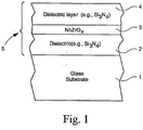
- Figure 1 is a side cross sectional view of a coated article according to an example embodiment of this invention.
- the coated article includes at least substrate 1 (e.g., clear, green, bronze, grey, blue, or blue-green glass substrate from about 1.0 to 12.0 mm thick), first optional dielectric layer 2 (e.g., of or including silicon nitride (e.g., Si 3 N 4 ), tin oxide, or some other suitable dielectric such as a metal oxide and/or nitride), infrared (IR) reflecting layer 3 of or including niobium zirconium (NbZr) and/or an 7 oxide of niobium zirconium (NbZrO x ), and second dielectric layer 4 (e.g., of or including silicon nitride (e.g., Si 3 N 4 ), tin oxide, or some other suitable dielectric such as a metal oxide and/or nitride).
- substrate 1 e.g., clear, green, bronze
- the bottom dielectric layer 2 may be omitted so that the IR reflecting layer 3 is located in contact with the glass substrate. Also, it is possible to nitride the NbZrO x IR reflecting layer to some extent in certain alternative embodiments of this invention.
- a protective overcoat of or including a material such as zirconium oxide may be provided over layers 2-4 in certain example embodiments of this invention.
- Example protective overcoats comprising silicon nitride, zirconium oxide and/or chromium oxide which may be optionally used in certain example embodiments of this invention are described in U.S. Patent Application Serial No. 10/406,003, filed April 3, 2003 .
- coating 5 optionally may not include any metallic IR blocking or reflecting layer of Ag or Au.
- NbZr and/or NbZrO x inclusive IR reflecting layer(s) 3 may be the only IR reflecting layer in coating 5, although many such layers may be provided in certain instances.
- NbZr and/or NbZrO x IR reflecting layer 3 reflects at least some IR radiation.
- Overall coating 5 includes at least layers 2-4.
- oxide and "nitride” as used herein include various stoichiometries.
- silicon nitride includes stoichiometric Si 3 N 4 , as well as non-stoichiometric silicon nitride.
- Silicon nitride may of course be doped with Al, Zr and/or any other suitable metal.
- a zirconium oxide overcoat may be doped with Si, or other materials.
- Layers 2-4 may be deposited on substrate 1 via magnetron sputtering, any other type of sputtering, or via any other suitable technique in different embodiments of this invention.
- the use of Zr and Nb in IR reflecting layer 3 allows the resulting coated article to realize excellent chemical and mechanical durability, and also good thermal performance.
- the use of NbZr and/or NbZrO x in IR reflecting layer(s) 3 allows the resulting coated article(s) to achieve: (a) improved corrosion resistance to alkaline solutions such as NaOH (compared to layer stacks of glass/Si 3 N 4 /Nb/Si 3 N 4 and glass/Si 3 N 4 /NbN x /Si 3 N 4 ); (b) excellent thermal performance comparable to that of Nb and NbN x ; (c) good mechanical performance such as scratch resistance; and/or (d) good color stability upon heat treatment (e.g., lower ⁇ E* value(s) than coated articles with layer stacks of glass/Si 3 N 4 /NiCr/Si 3 N 4 ). It has surprisingly been found that in certain example instances, the use of NbZr
- oxygen (O 2 ) gas flows when sputtering a NbZr target(s) may be from about 0.5 to 6 sccm/kW, more preferably from about 1 to 4 sccm/kW, and most preferably from about 2 to 3 sccm/kW (where kW is a unit of power used in sputtering). These oxygen flows, have been found to lead to significantly improved ⁇ E* value(s).
- ⁇ E* value(s) can be lowered even further due to oxiding the NbZr inclusive layer to form a layer comprising NbZrO x , compared to non-oxided layers of NbZr and NbZrN x .
- the Zr:Nb ratio (atomic %) layer 3 may be from about 0.001 to 1.0, more preferably from about 0.001 to 0.60, and even more preferably from about 0.004 to 0.50, and still more preferably from 0.05 to 0.2 (e.g., 0.11).
- the IR reflecting layer may include from about 0.1 to 60% Zr, more preferably from about 0.1 to 40% Zr, even more preferably from 0.1 to 20%, still more preferably from 0.1 to 15%, more preferably from about 0.4 to 15 % Zr, and most preferably from 3 to 12% Zr (atomic %). Surprising durability improvement has been observed even for very low Zr contents determined to be less than 0.44 atomic % (Zr/Nb ratio of 0.00438), while at the same time thermal performance is comparable to the use of Nb.
- the atomic ratio in the layer of oxygen to the total combination of Nb and Zr may be represented, in certain example embodiments, by (Nb+Zr) x O y , where the ratio y/x (i.e., the ratio of oxygen to Nb+Zr) is from 0.00001 to 1.0, even more preferably from 0.03 to 0.20, and still more preferably from 0.05 to 0.15. This ratio is applicable before and/or after heat treatment.
- the NbZr inclusive layer is partially oxided, although such oxidation is certainly material in that it results in significant advantages over non-oxided versions.
- Fig. 1 illustrates coating 5 in a manner where NbZr and/or NbZrO x layer 3 is in direct contact with dielectric layers 2 and 4, and wherein layer 3 is the only IR reflecting layer in the coating
- the instant invention is not so limited.
- Other layer(s) may be provided between layers 2 and 3 (and/or between layers 3 and 4) in certain other embodiments of this invention.
- other layer(s) may be provided between substrate 1 and layer 2 in certain embodiments of this invention; and/or other layer(s) (not shown) may be provided on substrate 1 over layer 4 in certain embodiments of this invention.
- the coating 5 or layers thereof is/are “on” or “supported by” substrate 1 (directly or indirectly), other layer(s) may be provided therebetween.
- the layer system 5 and layers thereof shown in Fig. 1 are considered “on” the substrate 1 even when other layer(s) (not shown) are provided therebetween (i.e., the terms “on” and “supported by” as used herein are not limited to directly contacting).
- more than one NbZr and/or NbZrO x IR reflecting layer may be provided in alternative embodiments of this invention.
- dielectric antireflection layer 2 may have an index of refraction "n" of from 1.7 to 2.7, more preferably from 1.9 to 2.5 in certain embodiments, while layer 4 may have an index of refraction "n” of from about 1.4 to 2.5, more preferably from 1.9 to 2.3.
- layer 3 when comprising an oxide of NbZr may have an index "n" of from about 2.0 to 3.2, more preferably from 2.2 to 3.0, and most preferably from 2.4 to 2.9; and may have an extinction coefficient "k" of from 2.5 to 4.5, more preferably from 3.0 to 4.0, and most preferably from 3.3 to 3.8.
- layers 2 and/or 4 comprise silicon nitride (e.g., Si 3 N 4 )
- sputtering targets including Si employed to form these layers may or may not be admixed with up to 1-40% by weight aluminum, zirconium and/or stainless steel (e.g. SS#316), with about this amount then appearing in the layers so formed. Even with this amount(s) of aluminum and/or stainless steel, such layers 2 and 4 are still considered dielectric layers herein.
- coated articles according to other embodiments of this invention may comprise IG (insulating glass) window units.
- coating 5 from Fig. 1 may be provided on the inner wall of the outer substrate of the IG unit, and/or on the inner wall of the inner substrate, or in any other suitable location in other embodiments of this invention.
- example thicknesses and materials for the respective layers 2-4 on the glass substrate 1 are as follows: Table 1 (Example non-limiting thicknesses) Layer Example Range ( ⁇ ) Preferred ( ⁇ ) Best ( ⁇ ) silicon nitride (layer 2): 0-1,500 ⁇ 20-1300 ⁇ 50-1200 ⁇ NbZr or NbZrO x (layer 3): 30-700 ⁇ 100-500 ⁇ 120-350 ⁇ silicon nitride (layer 4): 10-900 ⁇ 100-800 ⁇ 150-500 ⁇
- the color stability with HT may result in substantial matchability between heat-treated and non-heat treated versions of the coating or layer system.
- two glass substrates having the same coating system thereon appear to the naked human eye to look substantially the same.
- the value(s) ⁇ E* is important in determining whether or not there is matchability, or substantial color matchability upon HT, in the context of certain embodiments of this invention (i.e., the term ⁇ E* is important in determining color stability upon HT). Color herein is described by reference to the conventional a*, b* values. For example, the term ⁇ a* is indicative of how much color value a* changes due to HT. The term ⁇ E* (and ⁇ E) is well understood in the art. The definition of the term ⁇ E* may be found, for example, in WO 02/090281 and/or U.S. Patent No. 6,475,626 .
- ⁇ E may be calculated using equation (1) by replacing a*, b*, L* with Hunter Lab values a h , b h , L h . Also within the scope of this invention and the quantification of ⁇ E* are the equivalent numbers if converted to those calculated by any other technique employing the same concept of ⁇ E* as defined above.
- coated articles Before heat treatment (HT) such as thermal tempering, in certain example embodiments of this invention coated articles have color characteristics as follows in Table 2 (monolithic and/or IG unit). It is noted that subscript “G” stands for glass side reflective color, subscript “T” stands for transmissive color, and subscript “F” stands for film side color. As is known in the art, glass side (G) means reflective color when viewed from the glass side (as opposed to the layer/film side) of the coated article. Film side (F) means reflective color when viewed from the side of the coated article on which the coating 5 is provided.
- Table 2 monolithic and/or IG unit
- subscript “G” stands for glass side reflective color
- subscript “T” stands for transmissive color
- subscript “F” stands for film side color.
- glass side (G) means reflective color when viewed from the glass side (as opposed to the layer/film side) of the coated article.
- Film side (F) means reflective color when viewed from the side of the coated article on
- Table 3 set forth below illustrates certain characteristics of coated articles according to certain example embodiments of this invention after HT such as thermal tempering (monolithic and/or IG units) - the characteristics below in Table 2 (non-HT) are also applicable to HT coated articles herein, except for the additions set forth in Table 3.
- the coated article may have a glass side reflective ⁇ E* value due to heat treatment of no greater than 4.0, more preferably no greater than 3.0, more preferably no greater than 2.5, still more preferably no greater than 2.0, even more preferably no greater than 1.5, and sometimes even no greater than 1.0.
- Examples 1-2 and 4 are non-oxided reference examples (i.e., NbZr IR reflecting layers), whereas Examples 3 and 5-7 are examples of this invention where the IR reflecting layer is oxided so as to include NbZrO x .
- Examples 1-2 were monolithic coated articles (each ultimately annealed and heat treated, although not all embodiments herein need be HT), with the layer stack as shown in Fig. 1 .
- the Si 3 N 4 layers 2 and 4 in each example were deposited by sputtering a silicon target (doped with about 10% Al) in an atmosphere including nitrogen and argon gases.
- the NbZr IR reflecting layer 3 in each example was deposited by sputtering a target of about 90% Nb and about 10% Zr in an atmosphere including argon gas.
- the following sputtering process parameters were used in depositing the coating.
- Example 2 the following sputtering process parameters were used in depositing the coating. Again, line speed is in inches per minute (IPM), and gas flows were in units of sccm: TABLE 5: Example 2 Coating Process Parameters Layer Power Voltage Line Speed # Passes Ar flow N flow O flow SiN layer 2: 2.5 kW 485 V 42.8 2 40 55 0 NbZr layer 3: 1.0 kW 369 V 31 1 30 0 0 SiN layer 4: 2.5 kW 484 V 32.9 2 40 55 0
- each of these Examples could easily have been transformed into an NbZrN x embodiment by merely turning on an appropriate amount of nitrogen gas flow during the sputtering deposition of the IR reflecting layer 3.
- the NbZr layer 3 can be nitrided as a result of nitrogen diffusion during heat treatment, even if no nitrogen is intentionally added during sputtering.
- NbZr deposited over silicon nitride, and/or NbZr overcoated with silicon nitride may have some nitrogen therein due to diffusion even before heat treatment.
- Examples 1-2 After being sputtered, Examples 1-2 had the following characteristics (annealed and non-HT, monolithic) (Ill. C, 2 degree observer): TABLE 6: Characteristics (non- HT) Parameter Ex. 1 Ex. 2 T vis (TY)(transmission): 19.4% 20.9% a* T -1.5 -1.4 b* T 3.9 -4.9 L* T 51.2 52.9 R G Y(glass side refl. %): 19.0% 30.8 % a* G : -0.7 -2.9 b* G : -19.2 -0.9 L* G : 50.7 62.3 R F Y (film side refl.
- Example 1 Glass/Si 3 N 4 (850 ⁇ )/NbZr(190 ⁇ )/Si 3 N 4 (210 ⁇ )
- Example 2 Glass/Si 3 N 4 (190 ⁇ )/NbZr(200 ⁇ )/Si 3 N 4 (300 ⁇ )
- Examples 1-2 After being sputter coated, Examples 1-2 (as in Tables 4-7 above with no ZrO overcoat) were heat treated for 10 minutes at about 625 degrees C. Table 8 below sets forth certain color stability characteristics of Examples 1-2 upon/after such heat treatment (HT). TABLE 8: Glass Side Reflective Color Stability Upon HT Parameter Example 1 Example 2 ⁇ E* G : 1.7 2.5
- Examples 1-2 were characterized by satisfactory glass side reflective ⁇ E* values (the lower the better). These low values illustrate how little the glass side reflective optical characteristics of the coating change upon HT. This is indicative of good color stability upon heat treatment. Additionally, it has been found in other NbZr examples similar to Examples 1-2 but having higher Zr content of about 10% in layer 3 that glass side reflective ⁇ E* is from about 1.9 to 2.0.
- Examples 3-7 illustrate the unexpected finding that oxiding the NbZr IR reflecting layer 3 even further lowers the ⁇ E* value(s) according to certain embodiments of this invention.
- the coatings of Examples 1-2 with NbZr layers 3 have good color stability upon HT, still lower ⁇ E* value(s) would represent a significant commercial advantage.
- the human eye is able to notice slight differences in appearance between two samples having a ⁇ E* value of 2.0 (the first sample being non-HT and the second sample having been subjected to HT). However, the human eye is typically not able to notice slight differences in appearance between two samples having a ⁇ E* value of less than about 1.5.
- the examples were monolithic coated articles (each ultimately annealed and heat treated, although not all embodiments herein need be HT), with the layer stack as shown in Fig. 1 .
- the Si 3 N 4 layers 2 and 4 in all below Examples 3-7 were deposited by sputtering a silicon target (doped with about 10% Al) in an atmosphere including nitrogen and argon gases.
- the NbZrO x IR reflecting layer 3 in Examples 3-6 was deposited by sputtering a target of about 90% Nb and about 10% Zr, whereas the NbZrO x IR reflecting layer 3 in Example 7 was deposited by sputtering a target of about 85% Nb and about 15% Zr.
- Example 3 the following sputtering process parameters were used in depositing the coating.
- Line speed is in inches per minute (IPM)
- gas (Ar, O and N) flows were in units of seem: TABLE 9:
- Example 3 Coating Process Parameters Layer Power Voltage Line Speed # Passes Ar flow N flow O flow SiN layer 2: 1.0 kW 434 V 46.3 5 40 40 0 NbZr layer 3: 1.0 kW 374 V 58 2 30 0 3 SiN layer 4: 1.0 kW 437 V 46.2 7 40 55 0
- Example 3 Characteristics (non- HT) Parameter Ex.3 T vis (TY)(transmission): 19.5% a* T -1.1 b* T -4.3 L* T 52.9 R G Y(glass side refl. %): 30.4 % a* G : -2.7 b* G : -0.9 L* G : 62 R F Y (film side refl. %): 26.5% a* F : -0.4 b* F : 18.2 L* F : 58.5 Emissivity (hemispherical): 0.34 R s (sheet resistance; ohms/sq.): 48.1
- Example 3 had a layer stack as follows, set forth in Table 7. The thicknesses and stoichiometries listed below in Table 11. The glass substrate was clear and about 6 mm thick. TABLE 11: Coating in Example 3 Example 3: Glass/Si 3 N 4 (230 ⁇ )/NbZrO(175 ⁇ )/Si 3 N 4 (320 ⁇ )
- Example 3 was then evaluated and tested for durability, showing excellent performance in standard mechanical and chemical tests as coated and after HT. For example, the Teledyne scratch test with a 500 gm load did not produce noticeable scratches on either sample. A taber abrasion test after 500 revolutions was also passed. A one hour NaOH boil test was also passed although some changes in color were observed.
- Example 3 After being sputter coated, Example 3 was heat treated for about 10 minutes at about 625 degrees C. Table 12 below sets forth certain color stability characteristics of Examples 3-7. Table 12 includes the amount of oxygen used in sputtering the IR reflecting layer 3 in each of Examples 3-7, and also includes the glass side reflective ⁇ E* values due to HT (the IR reflecting layers 3 for each of Examples 3-7 was deposited using 30 sccm Ar gas flow and 1 kW of power). TABLE 12: Glass Side Reflective Color Stability Upon HT Oxygen Flow (sccm) ⁇ E* G Ex. 3 3 0.9 Ex. 4 0 2.6 Ex. 5 2 1.2 Ex. 6 4 2.6 Ex. 7 3 0.8
- Examples 1-2 were characterized by satisfactory glass side reflective ⁇ E* values (the lower the better). These low values illustrate how little the glass side reflective optical characteristics of the coating change upon HT. This is indicative of good color stability upon heat treatment. Additionally, it has been found in other NbZr examples similar to Examples 1-2 but having higher Zr content of about 10% in layer 3 that glass side reflective ⁇ E* is from about 1.9 to 2.0.
- Table 12 illustrates that even lower ⁇ E* (glass side) values can be achieved by oxidizing the NbZr inclusive IR reflecting layer 3 so as to form a layer comprising NbZrO x . This is shown by the fact that the NbZrO x examples (Examples 3 and 5-7) were characterized by ⁇ E* (glass side) values equal to or lower than non-oxided Example 4 as shown in Table 12. Furthermore, Table 12 illustrates that oxygen gas flows in the range of from about 2 to 3 sccm/kW unexpectedly allowed for the best ⁇ E* (glass side) values (i.e., the lowest) to be achieved.
- Examples 8-18 also illustrate the unexpected finding that oxiding the NbZr IR reflecting layer 3 even further lowers the ⁇ E* value(s) according to certain embodiments of this invention.
- the layer stack for each of Examples 8-18 was glass/Si 3 N 4 /NbZrO/Si 3 N 4 .
- the silicon nitride overcoat was about 280 to 330 angstroms thick; and in Examples 11-13 and 17 the silicon nitride (doped with Al in all cases in these examples) undercoat was about 800 angstroms thick and the silicon nitride overcoat was about 200 to 300 angstroms thick.
- Examples 8-13 used sputtering targets for layer 3 having a 5% Zr content, whereas Examples 14-17 used sputtering targets having a 10% Zr content, and Example 18 used a target with a 15% Zr content.
- the example non-limiting heat treatment used in determining the ⁇ E* data for Examples 8-18 was for about ten minutes at about 625 degrees C (although other types of HT may of coursed be used - the ⁇ E* values will be lower for shorter periods of HT and/or lower temperatures during HT).
- Table 13 - Examples 8-18 Ex.
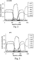
- Figs. 2-3 are XPS graphs of a coated article similar to Example 16, where the oxygen gas flow during deposition of the NbZrO layer 3 was 3 sccm.
- Fig. 2 is before heat treatment, whereas Fig. 3 is after heat treatment for about ten minutes at about 625 degrees C.
- the spike in Nb content in the central area of each of the Fig. 2 and Fig. 3 graphs illustrates the position of the NbZrO layer 3, whereas the pair of nitrogen spikes on either side thereof indicates silicon nitride layers 2 and 4.
- the increased oxygen content on the right sides of Figs. 2 and 3 is indicative of the glass substrate (i.e., the outer surface of the coated article is at the left of these figures whereas the glass substrate is at the right of these figures). It can be seen from Figs. 2-3 that the NbZrO layer 3 includes much more Nb than Zr, and also that the layer 3 is lightly nitrided.
- the ratio of oxygen to metals in layer 3 is from 0.09 to 0.15 in at least one part of the layer 3.
- NbZrO layer 3 is oxidation graded.
- the oxygen content in NbZrO layer 3 is higher near the interface with, for example, the overlying silicon nitride layer 4 compared to certain other portions of layer 3.
- This oxygen gradient has been found to be particularly beneficial at the interface with the top silicon nitride layer 4 since the higher oxygen content at this location tends to reduce the amount of nitrogen which diffuses into layer 3, before and/or after HT.
- this oxygen gradient i.e., higher oxygen content in layer 3 proximate the interface with the top silicon nitride layer
- nitrogen tends to diffuse into the NbZrO layer 3 during sputtering thereof and/or thereafter, so as to create a gradient layer 3 where the nitrogen content decreases towards the center of the layer 3. It has been found that the layer 3 can tolerate nitrogen more easily with smaller Zr content.
- Intensity of reflected visible wavelength light i.e. "reflectance” is defined by its percentage and is reported as R x Y (i.e. the Y value cited below in ASTM E-308-85), wherein "X” is either "G” for glass side or “F” for film side.
- Glass side e.g. “G”
- film side i.e. “F”
- Color characteristics are measured and reported herein using the CIE LAB a*, b* coordinates and scale (i.e. the CIE a*b* diagram, Ill. CIE-C, 2 degree observer). Other similar coordinates may be equivalently used such as by the subscript "h” to signify the conventional use of the Hunter Lab Scale, or Ill. CIE-C, 10° observer, or the CIE LUV u*v* coordinates.
- These scales are defined herein according to ASTM D-2244-93 "Standard Test Method for Calculation of Color Differences From Instrumentally Measured Color Coordinates" 9/15/93 as augmented by ASTM E-308-85, Annual Book of ASTM Standards, Vol. 06.01 "Standard Method for Computing the Colors of Objects by 10 Using the CIE System " and/or as reported in IES LIGHTING HANDBOOK 1981 Reference Volume .
- ED visible light transmittance
- T uv ultraviolet radiation transmittance
- TS Total solar energy transmittance
- visible transmittance As reported herein, is characterized by the standard CIE Illuminant C, 2 degree observer, technique at 380 - 720 nm; near-infrared is 720 - 2500 nm; ultraviolet is 300 - 380 nm; and total solar is 300 - 2500 nm.
- a particular infrared range i.e. 2,500 - 40,000 nm is employed.
- Visible transmittance can be measured using known, conventional techniques. For example, by using a spectrophotometer, such as a Perkin Elmer Lambda 900 or Hitachi U4001, a spectral curve of transmission is obtained. Visible transmission is then calculated using the aforesaid ASTM 308/2244-93 methodology. A lesser number of wavelength points may be employed than prescribed, if desired.
- Another technique for measuring visible transmittance is to employ a spectrometer such as a commercially available Spectrogard spectrophotometer manufactured by Pacific Scientific Corporation. This device measures and reports visible transmittance directly. As reported and measured herein, visible transmittance (i.e. the Y value in the CIE tristimulus system, ASTM E-308-85) uses the Ill. C.,2 degree observer.
- Sheet resistance is a well known term in the art and is used herein in accordance with its well known meaning. It is here reported in ohms per square units. Generally speaking, this term refers to the resistance in ohms for any square of a layer system on a glass substrate to an electric current passed through the layer system. Sheet resistance is an indication of how well the layer or layer system is reflecting infrared energy, and is thus often used along with emittance as a measure of this characteristic. "Sheet resistance” may for example be conveniently measured by using a 4-point probe ohmmeter, such as a dispensable 4-point resistivity probe with a Magnetron Instruments Corp. head, Model M-800 produced by Signatone Corp. of Santa Clara, California.
- heat treatment and "heat treating” as used herein mean heating the article to a temperature sufficient to enabling thermal tempering, bending, and/or heat strengthening of the glass inclusive article.
- This definition includes, for example, heating a coated article to a temperature of at least about 580 or 600 degrees C for a sufficient period to enable tempering and/or heat strengthening.
- the HT may be for at least about 4 or 5 minutes.
Landscapes
- Chemical & Material Sciences (AREA)
- Materials Engineering (AREA)
- Engineering & Computer Science (AREA)
- Chemical Kinetics & Catalysis (AREA)
- Organic Chemistry (AREA)
- General Chemical & Material Sciences (AREA)
- Geochemistry & Mineralogy (AREA)
- Life Sciences & Earth Sciences (AREA)
- Mechanical Engineering (AREA)
- Metallurgy (AREA)
- Inorganic Chemistry (AREA)
- Surface Treatment Of Glass (AREA)
- Laminated Bodies (AREA)
- Other Surface Treatments For Metallic Materials (AREA)
Priority Applications (1)
| Application Number | Priority Date | Filing Date | Title |
|---|---|---|---|
| PL04784024T PL1667809T3 (pl) | 2003-09-29 | 2004-09-15 | Nadający się do obróbki cieplnej powlekany wyrób zawierający warstwę odbijającą podczerwień z niobu i cyrkonu i metoda jego wytwarzania |
Applications Claiming Priority (2)
| Application Number | Priority Date | Filing Date | Title |
|---|---|---|---|
| US10/672,065 US6908679B2 (en) | 2003-04-25 | 2003-09-29 | Heat treatable coated article with niobium zirconium inclusive IR reflecting layer and method of making same |
| PCT/US2004/030026 WO2005034190A2 (en) | 2003-09-29 | 2004-09-15 | Heat treatable coated article with niobium zirconium inclusive ir refelecting layer and method of making same |
Publications (3)
| Publication Number | Publication Date |
|---|---|
| EP1667809A2 EP1667809A2 (en) | 2006-06-14 |
| EP1667809A4 EP1667809A4 (en) | 2010-07-07 |
| EP1667809B1 true EP1667809B1 (en) | 2018-10-17 |
Family
ID=34422017
Family Applications (1)
| Application Number | Title | Priority Date | Filing Date |
|---|---|---|---|
| EP04784024.4A Expired - Lifetime EP1667809B1 (en) | 2003-09-29 | 2004-09-15 | Heat treatable coated article with niobium zirconium inclusive ir refelecting layer and method of making same |
Country Status (7)
| Country | Link |
|---|---|
| US (1) | US6908679B2 (pl) |
| EP (1) | EP1667809B1 (pl) |
| CA (1) | CA2538081C (pl) |
| ES (1) | ES2704825T3 (pl) |
| PL (1) | PL1667809T3 (pl) |
| TR (1) | TR201900588T4 (pl) |
| WO (1) | WO2005034190A2 (pl) |
Families Citing this family (30)
| Publication number | Priority date | Publication date | Assignee | Title |
|---|---|---|---|---|
| US6967060B2 (en) * | 2003-05-09 | 2005-11-22 | Guardian Industries Corp. | Coated article with niobium zirconium inclusive layer(s) and method of making same |
| US7081301B2 (en) * | 2003-10-14 | 2006-07-25 | Guardian Industries Corp. | Coated article with and oxide of silicon zirconium or zirconium yttrium oxide in overcoat, and/or niobium nitrude in ir reflecting layer |
| US7153578B2 (en) * | 2004-12-06 | 2006-12-26 | Guardian Industries Corp | Coated article with low-E coating including zirconium silicon oxynitride and methods of making same |
| US7592068B2 (en) * | 2005-01-19 | 2009-09-22 | Centre Luxembourgeois De Recherches Pour Le Verre Et La Ceramique S.A. (C.R.V.C.) | Heat treatable coated article with zirconium silicon oxynitride layer(s) and methods of making same |
| AU2006247708A1 (en) | 2005-05-12 | 2006-11-23 | Agc Flat Glass North America, Inc. | Low emissivity coating with low solar heat gain coefficient, enhanced chemical and mechanical properties and method of making the same |
| US8287701B2 (en) | 2005-07-12 | 2012-10-16 | Verre et la Ceramique S.A. (C.R.V.C.) | Spandrel coating and method |
| FR2889182B1 (fr) * | 2005-07-29 | 2007-10-26 | Saint Gobain | Vitrage muni d'un empilement de couches minces agissant sur le rayonnement solaire |
| US7632543B2 (en) | 2006-12-05 | 2009-12-15 | Guardian Industries Corp. | Method of making IG window unit and forming silicon oxide based hydrophilic coating using chlorosilane vapor deposition |
| US7901781B2 (en) | 2007-11-23 | 2011-03-08 | Agc Flat Glass North America, Inc. | Low emissivity coating with low solar heat gain coefficient, enhanced chemical and mechanical properties and method of making the same |
| US8337988B2 (en) * | 2010-04-22 | 2012-12-25 | Centre Luxembourgeois De Recherches Pour Le Verre Et La Ceramique S.A. (C.R.V.C.) | Coated article having low-E coating with absorber layer(s) |
| US8445111B2 (en) | 2010-10-14 | 2013-05-21 | Guardian Industries Corp. | Gadolinium oxide-doped zirconium oxide overcoat and/or method of making the same |
| US8703281B2 (en) * | 2011-01-11 | 2014-04-22 | Guardian Industries Corp. | Heat treatable coated article with breaker layer |
| US9017821B2 (en) | 2012-02-22 | 2015-04-28 | Guardian Industries Corp. | Coated article with low-E coating having multilayer overcoat and method of making same |
| US9869016B2 (en) | 2012-02-22 | 2018-01-16 | Guardian Glass, LLC | Coated article with low-E coating having multilayer overcoat and method of making same |
| FR2992958B1 (fr) * | 2012-07-06 | 2017-07-21 | Saint Gobain | Vitrage isolant |
| FR2992959B1 (fr) * | 2012-07-06 | 2016-12-23 | Saint Gobain | Vitrage isolant comprenant deux couches fonctionnelles |
| CN104395257B (zh) * | 2012-07-06 | 2018-08-28 | 法国圣戈班玻璃厂 | 隔热窗玻璃 |
| FR3019541B1 (fr) * | 2014-04-08 | 2021-04-02 | Saint Gobain | Substrat muni d'un empilement a proprietes thermiques |
| AU2016397939B2 (en) * | 2016-03-14 | 2021-01-28 | Guardian Europe S.A.R.L. | Green colored heat treatable coated article having low solar factor value |
| MY193026A (en) * | 2016-03-15 | 2022-09-23 | Guardian Glass Llc | Bronze colored heat treatable coated article having low solar factor value |
| AU2016397694B2 (en) * | 2016-03-15 | 2021-09-16 | Guardian Europe S.A.R.L. | Grey colored heat treatable coated article having low solar factor value |
| EP3529073B1 (en) | 2016-10-18 | 2024-11-27 | Guardian Glass Management Services W.L.L. | Silver colored coated article with low-e coating having absorber layer and low visible transmission |
| JP7308748B2 (ja) | 2016-10-18 | 2023-07-14 | ガーディアン・グラス・エルエルシー | 低い可視光透過率の、吸収体層を有する低e被膜を含む灰色に着色した被覆物品 |
| WO2018109534A1 (en) * | 2016-12-16 | 2018-06-21 | Guardian Glass Holding S.P.C. | Heat treatable coated article for use in backsplash applications |
| FR3065211A1 (fr) * | 2017-04-12 | 2018-10-19 | Saint-Gobain Glass France | Vitrage reflechissant comprenant une couche mince de nitrure de silicium riche en silicium |
| US10752541B2 (en) | 2018-07-16 | 2020-08-25 | Guardian Glass, LLC | Low-E matchable coated articles having doped seed layer under silver, and corresponding methods |
| US10759693B2 (en) * | 2018-07-16 | 2020-09-01 | Guardian Glass, LLC | Low-E matchable coated articles having absorber film and corresponding methods |
| US10640418B2 (en) * | 2018-07-16 | 2020-05-05 | Guardian Glass, LLC | Low-E matchable coated articles having absorber film and corresponding methods |
| US10787385B2 (en) * | 2018-07-16 | 2020-09-29 | Guardian Glass, LLC | Low-E matchable coated articles having absorber film and corresponding methods |
| US10301215B1 (en) * | 2018-07-16 | 2019-05-28 | Guardian Glass, LLC | Low-E matchable coated articles having doped seed layer under silver, and corresponding methods |
Family Cites Families (29)
| Publication number | Priority date | Publication date | Assignee | Title |
|---|---|---|---|---|
| LU52726A1 (pl) * | 1966-12-30 | 1968-08-05 | ||
| US4071649A (en) * | 1973-03-30 | 1978-01-31 | Glaverbel-Mecaniver | Fireproof glasswork |
| NO157212C (no) * | 1982-09-21 | 1988-02-10 | Pilkington Brothers Plc | Fremgangsmaate for fremstilling av belegg med lav emisjonsevne. |
| AU585426B2 (en) * | 1986-01-29 | 1989-06-15 | Pilkington Brothers Plc | Coated glass |
| US5059295A (en) * | 1986-12-29 | 1991-10-22 | Ppg Industries, Inc. | Method of making low emissivity window |
| US5201926A (en) * | 1987-08-08 | 1993-04-13 | Leybold Aktiengesellschaft | Method for the production of coated glass with a high transmissivity in the visible spectral range and with a high reflectivity for thermal radiation |
| US5318685A (en) * | 1987-08-18 | 1994-06-07 | Cardinal Ig Company | Method of making metal oxide films having barrier properties |
| US5407733A (en) * | 1990-08-10 | 1995-04-18 | Viratec Thin Films, Inc. | Electrically-conductive, light-attenuating antireflection coating |
| FR2672884B1 (fr) * | 1991-02-20 | 1993-09-10 | Saint Gobain Vitrage Int | Couche protectrice sur un substrat conducteur. |
| JP3139031B2 (ja) * | 1991-02-21 | 2001-02-26 | 日本板硝子株式会社 | 熱線遮蔽ガラス |
| SG45418A1 (en) * | 1991-10-30 | 1998-01-16 | Asahi Glass Co Ltd | Method of making a heat treated coated glass |
| US5229194A (en) * | 1991-12-09 | 1993-07-20 | Guardian Industries Corp. | Heat treatable sputter-coated glass systems |
| US5395698A (en) * | 1993-06-04 | 1995-03-07 | Ppg Industries, Inc. | Neutral, low emissivity coated glass articles and method for making |
| US5688585A (en) * | 1993-08-05 | 1997-11-18 | Guardian Industries Corp. | Matchable, heat treatable, durable, IR-reflecting sputter-coated glasses and method of making same |
| US6352755B1 (en) * | 1994-10-04 | 2002-03-05 | Ppg Industries Ohio, Inc. | Alkali metal diffusion barrier layer |
| US5514476A (en) * | 1994-12-15 | 1996-05-07 | Guardian Industries Corp. | Low-E glass coating system and insulating glass units made therefrom |
| FR2728559B1 (fr) * | 1994-12-23 | 1997-01-31 | Saint Gobain Vitrage | Substrats en verre revetus d'un empilement de couches minces a proprietes de reflexion dans l'infrarouge et/ou dans le domaine du rayonnement solaire |
| US5557462A (en) * | 1995-01-17 | 1996-09-17 | Guardian Industries Corp. | Dual silver layer Low-E glass coating system and insulating glass units made therefrom |
| US6086210A (en) * | 1995-06-29 | 2000-07-11 | Cardinal Ig Company | Bendable mirrors and method of manufacture |
| FR2755962B1 (fr) * | 1996-11-21 | 1998-12-24 | Saint Gobain Vitrage | Vitrage comprenant un substrat muni d'un empilement de couches minces pour la protection solaire et/ou l'isolation thermique |
| JP2000294980A (ja) * | 1999-04-06 | 2000-10-20 | Nippon Sheet Glass Co Ltd | 透光性電磁波フィルタおよびその製造方法 |
| FR2799005B1 (fr) | 1999-09-23 | 2003-01-17 | Saint Gobain Vitrage | Vitrage muni d'un empilement de couches minces agissant sur le rayonnement solaire |
| US6514620B1 (en) * | 1999-12-06 | 2003-02-04 | Guardian Industries Corp. | Matchable low-E I G units and laminates and methods of making same |
| US6495263B2 (en) * | 1999-12-06 | 2002-12-17 | Guardian Industries Corp. | Low-E matchable coated articles and methods of making same |
| US6475626B1 (en) * | 1999-12-06 | 2002-11-05 | Guardian Industries Corp. | Low-E matchable coated articles and methods of making same |
| US6576349B2 (en) * | 2000-07-10 | 2003-06-10 | Guardian Industries Corp. | Heat treatable low-E coated articles and methods of making same |
| US6524714B1 (en) * | 2001-05-03 | 2003-02-25 | Guardian Industries Corp. | Heat treatable coated articles with metal nitride layer and methods of making same |
| AU2003268049A1 (en) | 2002-07-31 | 2004-02-16 | Cardinal Cg Compagny | Temperable high shading performance coatings |
| US6967060B2 (en) | 2003-05-09 | 2005-11-22 | Guardian Industries Corp. | Coated article with niobium zirconium inclusive layer(s) and method of making same |
-
2003
- 2003-09-29 US US10/672,065 patent/US6908679B2/en not_active Expired - Lifetime
-
2004
- 2004-09-15 ES ES04784024T patent/ES2704825T3/es not_active Expired - Lifetime
- 2004-09-15 CA CA2538081A patent/CA2538081C/en not_active Expired - Fee Related
- 2004-09-15 TR TR2019/00588T patent/TR201900588T4/tr unknown
- 2004-09-15 WO PCT/US2004/030026 patent/WO2005034190A2/en not_active Ceased
- 2004-09-15 EP EP04784024.4A patent/EP1667809B1/en not_active Expired - Lifetime
- 2004-09-15 PL PL04784024T patent/PL1667809T3/pl unknown
Non-Patent Citations (1)
| Title |
|---|
| None * |
Also Published As
| Publication number | Publication date |
|---|---|
| EP1667809A4 (en) | 2010-07-07 |
| US20040214013A1 (en) | 2004-10-28 |
| WO2005034190A3 (en) | 2005-08-11 |
| TR201900588T4 (tr) | 2019-02-21 |
| EP1667809A2 (en) | 2006-06-14 |
| US6908679B2 (en) | 2005-06-21 |
| CA2538081C (en) | 2011-02-22 |
| PL1667809T3 (pl) | 2019-02-28 |
| ES2704825T3 (es) | 2019-03-20 |
| WO2005034190A2 (en) | 2005-04-14 |
| CA2538081A1 (en) | 2005-04-14 |
Similar Documents
| Publication | Publication Date | Title |
|---|---|---|
| US6908679B2 (en) | Heat treatable coated article with niobium zirconium inclusive IR reflecting layer and method of making same | |
| EP1587766B1 (en) | Heat treatable coated article with niobium nitride ir reflecting layer and method of making same | |
| US7147924B2 (en) | Coated article with dual-layer protective overcoat of nitride and zirconium or chromium oxide | |
| EP1682346B1 (en) | Heat treatable coated article and method of making same | |
| EP1841706B1 (en) | Heat treatable coated article with zirconium silicon oxynitride layer(s) and methods of making same | |
| US6890659B2 (en) | Heat treatable coated article with niobium zirconium inclusive IR reflecting layer and method of making same | |
| US6852419B2 (en) | Heat treatable coated article with niobium chromium nitride IR reflecting layer and method of making same | |
| EP1597066B1 (en) | Heat treatable coated article with chromium nitride ir reflecting layer and method of making same | |
| US20040096671A1 (en) | Heat treatable coated articles with zirconium or zirconium nitride layer and methods of making same |
Legal Events
| Date | Code | Title | Description |
|---|---|---|---|
| PUAI | Public reference made under article 153(3) epc to a published international application that has entered the european phase |
Free format text: ORIGINAL CODE: 0009012 |
|
| 17P | Request for examination filed |
Effective date: 20060405 |
|
| AK | Designated contracting states |
Kind code of ref document: A2 Designated state(s): AT BE BG CH CY CZ DE DK EE ES FI FR GB GR HU IE IT LI LU MC NL PL PT RO SE SI SK TR |
|
| DAX | Request for extension of the european patent (deleted) | ||
| RIN1 | Information on inventor provided before grant (corrected) |
Inventor name: STACHOWIAK, GRZEGORZ Inventor name: CHONLAMAITRI, RATCHANEEKORN |
|
| A4 | Supplementary search report drawn up and despatched |
Effective date: 20100607 |
|
| RIC1 | Information provided on ipc code assigned before grant |
Ipc: C23C 14/00 20060101ALI20100531BHEP Ipc: C23C 14/08 20060101ALI20100531BHEP Ipc: C03C 17/34 20060101AFI20100531BHEP |
|
| 17Q | First examination report despatched |
Effective date: 20110610 |
|
| RAP1 | Party data changed (applicant data changed or rights of an application transferred) |
Owner name: GUARDIAN GLASS, LLC |
|
| REG | Reference to a national code |
Ref country code: DE Ref legal event code: R079 Ref document number: 602004053307 Country of ref document: DE Free format text: PREVIOUS MAIN CLASS: C03C0017340000 Ipc: B32B0017100000 |
|
| GRAP | Despatch of communication of intention to grant a patent |
Free format text: ORIGINAL CODE: EPIDOSNIGR1 |
|
| STAA | Information on the status of an ep patent application or granted ep patent |
Free format text: STATUS: GRANT OF PATENT IS INTENDED |
|
| RIC1 | Information provided on ipc code assigned before grant |
Ipc: B32B 17/10 20060101AFI20180322BHEP Ipc: C03C 17/36 20060101ALI20180322BHEP Ipc: C23C 14/18 20060101ALI20180322BHEP Ipc: C23C 14/00 20060101ALI20180322BHEP Ipc: C03C 17/34 20060101ALI20180322BHEP Ipc: C23C 14/08 20060101ALI20180322BHEP |
|
| INTG | Intention to grant announced |
Effective date: 20180409 |
|
| GRAS | Grant fee paid |
Free format text: ORIGINAL CODE: EPIDOSNIGR3 |
|
| GRAA | (expected) grant |
Free format text: ORIGINAL CODE: 0009210 |
|
| STAA | Information on the status of an ep patent application or granted ep patent |
Free format text: STATUS: THE PATENT HAS BEEN GRANTED |
|
| AK | Designated contracting states |
Kind code of ref document: B1 Designated state(s): AT BE BG CH CY CZ DE DK EE ES FI FR GB GR HU IE IT LI LU MC NL PL PT RO SE SI SK TR |
|
| REG | Reference to a national code |
Ref country code: GB Ref legal event code: FG4D |
|
| REG | Reference to a national code |
Ref country code: CH Ref legal event code: EP |
|
| REG | Reference to a national code |
Ref country code: IE Ref legal event code: FG4D |
|
| REG | Reference to a national code |
Ref country code: DE Ref legal event code: R096 Ref document number: 602004053307 Country of ref document: DE Ref country code: AT Ref legal event code: REF Ref document number: 1053505 Country of ref document: AT Kind code of ref document: T Effective date: 20181115 |
|
| REG | Reference to a national code |
Ref country code: NL Ref legal event code: MP Effective date: 20181017 |
|
| REG | Reference to a national code |
Ref country code: AT Ref legal event code: MK05 Ref document number: 1053505 Country of ref document: AT Kind code of ref document: T Effective date: 20181017 |
|
| REG | Reference to a national code |
Ref country code: ES Ref legal event code: FG2A Ref document number: 2704825 Country of ref document: ES Kind code of ref document: T3 Effective date: 20190320 |
|
| PG25 | Lapsed in a contracting state [announced via postgrant information from national office to epo] |
Ref country code: NL Free format text: LAPSE BECAUSE OF FAILURE TO SUBMIT A TRANSLATION OF THE DESCRIPTION OR TO PAY THE FEE WITHIN THE PRESCRIBED TIME-LIMIT Effective date: 20181017 |
|
| PG25 | Lapsed in a contracting state [announced via postgrant information from national office to epo] |
Ref country code: AT Free format text: LAPSE BECAUSE OF FAILURE TO SUBMIT A TRANSLATION OF THE DESCRIPTION OR TO PAY THE FEE WITHIN THE PRESCRIBED TIME-LIMIT Effective date: 20181017 Ref country code: BG Free format text: LAPSE BECAUSE OF FAILURE TO SUBMIT A TRANSLATION OF THE DESCRIPTION OR TO PAY THE FEE WITHIN THE PRESCRIBED TIME-LIMIT Effective date: 20190117 Ref country code: FI Free format text: LAPSE BECAUSE OF FAILURE TO SUBMIT A TRANSLATION OF THE DESCRIPTION OR TO PAY THE FEE WITHIN THE PRESCRIBED TIME-LIMIT Effective date: 20181017 |
|
| PG25 | Lapsed in a contracting state [announced via postgrant information from national office to epo] |
Ref country code: SE Free format text: LAPSE BECAUSE OF FAILURE TO SUBMIT A TRANSLATION OF THE DESCRIPTION OR TO PAY THE FEE WITHIN THE PRESCRIBED TIME-LIMIT Effective date: 20181017 Ref country code: GR Free format text: LAPSE BECAUSE OF FAILURE TO SUBMIT A TRANSLATION OF THE DESCRIPTION OR TO PAY THE FEE WITHIN THE PRESCRIBED TIME-LIMIT Effective date: 20190118 |
|
| REG | Reference to a national code |
Ref country code: DE Ref legal event code: R097 Ref document number: 602004053307 Country of ref document: DE |
|
| PG25 | Lapsed in a contracting state [announced via postgrant information from national office to epo] |
Ref country code: CZ Free format text: LAPSE BECAUSE OF FAILURE TO SUBMIT A TRANSLATION OF THE DESCRIPTION OR TO PAY THE FEE WITHIN THE PRESCRIBED TIME-LIMIT Effective date: 20181017 Ref country code: DK Free format text: LAPSE BECAUSE OF FAILURE TO SUBMIT A TRANSLATION OF THE DESCRIPTION OR TO PAY THE FEE WITHIN THE PRESCRIBED TIME-LIMIT Effective date: 20181017 |
|
| PLBE | No opposition filed within time limit |
Free format text: ORIGINAL CODE: 0009261 |
|
| STAA | Information on the status of an ep patent application or granted ep patent |
Free format text: STATUS: NO OPPOSITION FILED WITHIN TIME LIMIT |
|
| PG25 | Lapsed in a contracting state [announced via postgrant information from national office to epo] |
Ref country code: EE Free format text: LAPSE BECAUSE OF FAILURE TO SUBMIT A TRANSLATION OF THE DESCRIPTION OR TO PAY THE FEE WITHIN THE PRESCRIBED TIME-LIMIT Effective date: 20181017 Ref country code: RO Free format text: LAPSE BECAUSE OF FAILURE TO SUBMIT A TRANSLATION OF THE DESCRIPTION OR TO PAY THE FEE WITHIN THE PRESCRIBED TIME-LIMIT Effective date: 20181017 Ref country code: SK Free format text: LAPSE BECAUSE OF FAILURE TO SUBMIT A TRANSLATION OF THE DESCRIPTION OR TO PAY THE FEE WITHIN THE PRESCRIBED TIME-LIMIT Effective date: 20181017 |
|
| 26N | No opposition filed |
Effective date: 20190718 |
|
| PG25 | Lapsed in a contracting state [announced via postgrant information from national office to epo] |
Ref country code: SI Free format text: LAPSE BECAUSE OF FAILURE TO SUBMIT A TRANSLATION OF THE DESCRIPTION OR TO PAY THE FEE WITHIN THE PRESCRIBED TIME-LIMIT Effective date: 20181017 |
|
| PG25 | Lapsed in a contracting state [announced via postgrant information from national office to epo] |
Ref country code: MC Free format text: LAPSE BECAUSE OF FAILURE TO SUBMIT A TRANSLATION OF THE DESCRIPTION OR TO PAY THE FEE WITHIN THE PRESCRIBED TIME-LIMIT Effective date: 20181017 |
|
| REG | Reference to a national code |
Ref country code: CH Ref legal event code: PL |
|
| PG25 | Lapsed in a contracting state [announced via postgrant information from national office to epo] |
Ref country code: LU Free format text: LAPSE BECAUSE OF NON-PAYMENT OF DUE FEES Effective date: 20190915 Ref country code: CH Free format text: LAPSE BECAUSE OF NON-PAYMENT OF DUE FEES Effective date: 20190930 Ref country code: IE Free format text: LAPSE BECAUSE OF NON-PAYMENT OF DUE FEES Effective date: 20190915 Ref country code: LI Free format text: LAPSE BECAUSE OF NON-PAYMENT OF DUE FEES Effective date: 20190930 |
|
| REG | Reference to a national code |
Ref country code: BE Ref legal event code: MM Effective date: 20190930 |
|
| PG25 | Lapsed in a contracting state [announced via postgrant information from national office to epo] |
Ref country code: BE Free format text: LAPSE BECAUSE OF NON-PAYMENT OF DUE FEES Effective date: 20190930 |
|
| PG25 | Lapsed in a contracting state [announced via postgrant information from national office to epo] |
Ref country code: CY Free format text: LAPSE BECAUSE OF FAILURE TO SUBMIT A TRANSLATION OF THE DESCRIPTION OR TO PAY THE FEE WITHIN THE PRESCRIBED TIME-LIMIT Effective date: 20181017 |
|
| PG25 | Lapsed in a contracting state [announced via postgrant information from national office to epo] |
Ref country code: HU Free format text: LAPSE BECAUSE OF FAILURE TO SUBMIT A TRANSLATION OF THE DESCRIPTION OR TO PAY THE FEE WITHIN THE PRESCRIBED TIME-LIMIT; INVALID AB INITIO Effective date: 20040915 |
|
| PG25 | Lapsed in a contracting state [announced via postgrant information from national office to epo] |
Ref country code: PT Free format text: LAPSE BECAUSE OF FAILURE TO SUBMIT A TRANSLATION OF THE DESCRIPTION OR TO PAY THE FEE WITHIN THE PRESCRIBED TIME-LIMIT Effective date: 20181017 |
|
| PGFP | Annual fee paid to national office [announced via postgrant information from national office to epo] |
Ref country code: PL Payment date: 20230628 Year of fee payment: 20 |
|
| PGFP | Annual fee paid to national office [announced via postgrant information from national office to epo] |
Ref country code: TR Payment date: 20230914 Year of fee payment: 20 Ref country code: IT Payment date: 20230810 Year of fee payment: 20 Ref country code: GB Payment date: 20230727 Year of fee payment: 20 |
|
| PGFP | Annual fee paid to national office [announced via postgrant information from national office to epo] |
Ref country code: FR Payment date: 20230710 Year of fee payment: 20 Ref country code: DE Payment date: 20230718 Year of fee payment: 20 |
|
| PGFP | Annual fee paid to national office [announced via postgrant information from national office to epo] |
Ref country code: ES Payment date: 20231009 Year of fee payment: 20 |
|
| REG | Reference to a national code |
Ref country code: DE Ref legal event code: R071 Ref document number: 602004053307 Country of ref document: DE |
|
| REG | Reference to a national code |
Ref country code: ES Ref legal event code: FD2A Effective date: 20241001 |
|
| REG | Reference to a national code |
Ref country code: GB Ref legal event code: PE20 Expiry date: 20240914 |
|
| PG25 | Lapsed in a contracting state [announced via postgrant information from national office to epo] |
Ref country code: GB Free format text: LAPSE BECAUSE OF EXPIRATION OF PROTECTION Effective date: 20240914 |
|
| PG25 | Lapsed in a contracting state [announced via postgrant information from national office to epo] |
Ref country code: ES Free format text: LAPSE BECAUSE OF EXPIRATION OF PROTECTION Effective date: 20240916 |
|
| PG25 | Lapsed in a contracting state [announced via postgrant information from national office to epo] |
Ref country code: GB Free format text: LAPSE BECAUSE OF EXPIRATION OF PROTECTION Effective date: 20240914 Ref country code: ES Free format text: LAPSE BECAUSE OF EXPIRATION OF PROTECTION Effective date: 20240916 |