EP1667799B1 - Centrifuge with automatic balancing rotor - Google Patents
Centrifuge with automatic balancing rotor Download PDFInfo
- Publication number
- EP1667799B1 EP1667799B1 EP04821366A EP04821366A EP1667799B1 EP 1667799 B1 EP1667799 B1 EP 1667799B1 EP 04821366 A EP04821366 A EP 04821366A EP 04821366 A EP04821366 A EP 04821366A EP 1667799 B1 EP1667799 B1 EP 1667799B1
- Authority
- EP
- European Patent Office
- Prior art keywords
- balance weight
- rotor
- buckets
- balance
- automatic balancing
- Prior art date
- Legal status (The legal status is an assumption and is not a legal conclusion. Google has not performed a legal analysis and makes no representation as to the accuracy of the status listed.)
- Expired - Lifetime
Links
Images


Classifications
-
- B—PERFORMING OPERATIONS; TRANSPORTING
- B04—CENTRIFUGAL APPARATUS OR MACHINES FOR CARRYING-OUT PHYSICAL OR CHEMICAL PROCESSES
- B04B—CENTRIFUGES
- B04B9/00—Drives specially designed for centrifuges; Arrangement or disposition of transmission gearing; Suspending or balancing rotary bowls
- B04B9/14—Balancing rotary bowls ; Schrappers
-
- B—PERFORMING OPERATIONS; TRANSPORTING
- B04—CENTRIFUGAL APPARATUS OR MACHINES FOR CARRYING-OUT PHYSICAL OR CHEMICAL PROCESSES
- B04B—CENTRIFUGES
- B04B9/00—Drives specially designed for centrifuges; Arrangement or disposition of transmission gearing; Suspending or balancing rotary bowls
- B04B9/14—Balancing rotary bowls ; Schrappers
- B04B9/146—Imbalance detection devices
-
- B—PERFORMING OPERATIONS; TRANSPORTING
- B04—CENTRIFUGAL APPARATUS OR MACHINES FOR CARRYING-OUT PHYSICAL OR CHEMICAL PROCESSES
- B04B—CENTRIFUGES
- B04B5/00—Other centrifuges
- B04B5/04—Radial chamber apparatus for separating predominantly liquid mixtures, e.g. butyrometers
- B04B5/0407—Radial chamber apparatus for separating predominantly liquid mixtures, e.g. butyrometers for liquids contained in receptacles
- B04B5/0414—Radial chamber apparatus for separating predominantly liquid mixtures, e.g. butyrometers for liquids contained in receptacles comprising test tubes
- B04B5/0421—Radial chamber apparatus for separating predominantly liquid mixtures, e.g. butyrometers for liquids contained in receptacles comprising test tubes pivotably mounted
-
- Y—GENERAL TAGGING OF NEW TECHNOLOGICAL DEVELOPMENTS; GENERAL TAGGING OF CROSS-SECTIONAL TECHNOLOGIES SPANNING OVER SEVERAL SECTIONS OF THE IPC; TECHNICAL SUBJECTS COVERED BY FORMER USPC CROSS-REFERENCE ART COLLECTIONS [XRACs] AND DIGESTS
- Y10—TECHNICAL SUBJECTS COVERED BY FORMER USPC
- Y10T—TECHNICAL SUBJECTS COVERED BY FORMER US CLASSIFICATION
- Y10T74/00—Machine element or mechanism
- Y10T74/21—Elements
- Y10T74/2109—Balancing for drum, e.g., washing machine or arm-type structure, etc., centrifuge, etc.
Definitions
- the present invention relates, in general, to centrifuges comprising automatic balancing rotors and, more particularly, to centrifuges comprising an automatic balancing rotor which senses imbalance of the weight of samples, contained in buckets, prior to every centrifugal separation and radially moves balance weights, provided in rotor arms, according to the weight sensing result, thus dynamically maintaining balance during the centrifugal separation.
- centrifuges are apparatuses in which a rotor containing samples is rotated at high speed to apply a high centrifugal force to the samples, so that a high density fraction is moved radially outwards and a low density fraction is moved radially inwards, thus separating the fractions from each other.
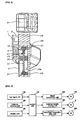
- FIG. 1 is a sectional view showing a conventional automatic balancing rotor for centrifuges.
- the conventional automatic balancing rotor for centrifuges uses a mechanism, in which a lever central body 636 is horizontally moved according to a control algorithm, to compensate for imbalance between samples contained in buckets supported by rotational arms 632.
- the lever moving mechanism includes a worm 662 which is axially coupled to a lever moving motor 652, a worm gear (not shown) which engages with the worm 662, a pinion 666 which is coaxially coupled to the worm gear, and the lever central body 636 having a rack 636a, which engages with the pinion 666.
- a pressure sensor 690 is provided under each rotational arm 632 to measured the weight of the sample contained in the associated bucket (not shown).
- a wiring layer 562 is integrally coupled to a lower part of the rotor to receive an electrical signal from the pressure sensors 690 and transmit an electrical signal to the lever moving motor 652 according to a control algorithm, thus balancing the centrifuge.
- the conventional automatic balancing rotor for centrifuges having the above-mentioned construction senses imbalance of the samples by measuring the weight of the buckets provided at both ends of the rotor lever, and controls the distance between each bucket and a rotating shaft of the rotor according to the weight difference of the samples, thus applying the same centrifugal force to the opposite buckets containing the samples. Thereby, the samples contained in the buckets maintain a dynamic balance state during the rotation of the rotor for centrifugal separation. More details are described in Korean Application No. 10-2002-0017498 (publication date: Apr.17, 2002 ) corresponding to WO 02/083 317 A1 which was filed by the inventor of the present invention, therefore further explanation is deemed unnecessary.
- JP 2002 221256 A discloses an automatic balancing rotor (see figures 5-8 ) comprising a plurality of rotating arms (24,25,26,27) having the same radial length and being arranged around a centrifugal rotating shaft (30), and being spaced out at regular angular intervals, with a plurality of buckets (20,21,22,23) containing samples therein supported by the rotating arms; a balance weight (29a,29b) provided in each of the rotating arms to be movable in a radial direction, thus compensating for imbalanced centrifugal force applied to the buckets during a centrifugal separation; and balance weight moving means (31 a,31 b) to horizontally move the balance weight in the radial direction of each of the rotating arms, in response to vibrations, sensed by an acceleration sensor (39), occurring due to imbalance.
- an object of the present invention is to provide a centrifuge comprising an automatic balancing rotor which compensates for an imbalance of a centrifugal force due to a weight difference of samples by horizontally moving balance weights provided in rotor arms without changing the length of the rotor arms, thus reducing the space that the automatic balancing rotor occupies, and applying the same centrifugal force to the samples contained in the buckets, and preventing the rotor from being affected by back lash during the automatic balancing process.
- a centrifuge comprising an automatic balancing rotor according to the present invention
- imbalance of a centrifugal force of the rotor due to a weight difference of samples is compensated for by controlling rotational radii of balance weights provided in rotor arms. Therefore, vibration of the automatic balancing rotor due to imbalance is prevented from occurring during centrifugal separation, thereby the lifetime of the automatic balancing rotor and of a centrifuge having the rotor is extended, and the samples are prevented from damage.
- the automatic balancing three-arm rotor of the present invention using a balance weight moving method can reduce the space required for centrifugal separation, therefore it is particularly useful in a centrifuge having a large capacity.
- the slot to guide the balance weight can be longitudinally formed through nearly all of the rotor arm, a sufficient balance weight moving distance is ensured, thereby minimizing the effect of back lash occurring between the balance weight and the balance weight moving shaft
- the present invention provides a centrifuge comprising an automatic balancing rotor according to claim 1.
- the buckets may be supported in spaces defined between the rotating arms, respectively.
- each of the rotating arms may include a slot formed through the rotating arm in the radial direction to receive therein the balance weight and guide the horizontal movement of the balance weight.
- the balance weight may have an internal thread formed through a center of the balance weight
- the balance weight moving means may have: a balance weight moving motor, a worm axially coupled to the balance weight moving motor, a worm gear engaging with the worm; and a balance weight moving shaft radially provided in the slot of the rotating arm and having an external thread on an outer surface thereof to engage with the internal thread of the balance weight
- the balance weight moving shaft is coaxially coupled at an end thereof to the worm gear.
- the automatic balancing rotor may further include a reference position sensing means provided at a predetermined position in the slot of the rotating arm to sense the balance weight placed at a reference position.
- FIG. 2 is a perspective view of an automatic balancing rotor for centrifuges, according to an embodiment of the present invention.
- FIG. 3 is an exploded perspective view of the automatic balancing rotor of FIG. 2 .
- FIG. 4 is a sectional view of the rotor taken along the line A-A of FIG. 2 .
- a three-arm swing rotor is shown as an example. As shown in FIGS.
- the automatic balancing rotor for centrifuges includes three rotor arms 29 which support a plurality of buckets 31 containing samples therein
- the automatic balancing rotor further includes a balance weight 15 which is provided in each of the rotor arms 29 to compensate for imbalanced centrifugal force applied to the buckets 31 during a centrifugal separation" and a balance weight moving means to horizontally move each balance weight 15 in the radial direction of each rotating arm 29.
- the rotor arms 29 are formed by cutting portions of a circular plate having a predetermined thickness at regular angular intervals, so that the buckets 31 are disposed in the cut portions.
- the rotor arms 29 are spaced out at 120° intervals.
- a pair of bucket support pins 33 is provided on opposite sidewalls of each rotor arm 29 to rotatably support each bucket 31.
- each bucket 31 is supported by the cooperation of two adjacent rotor arms 29.
- a slot 29a is formed through each rotating arm 29 in the radial direction to receive therein each balance weight 15 and guide the horizontal movement of the balance weight 15.
- the slot 29a has an elongated rectangular hole shape.
- the balance weight 15 have a hexahedral shape to prevent the balance weight 15 from rolling in the slot 29a
- An internal thread (not shown) is formed through the center of each balance weight 15.
- Each balance weight moving means has a balance weight moving motor 5 which is provided on a central portion of the automatic balancing rotor such that an output shaft of the balance weight moving motor 5 is vertically disposed.
- the balance weight moving means further has a worm 7 which is axially coupled to an end of the output shaft of the balance weight moving motor 5, and a balance weight moving shaft 17 which is longitudinally provided in the slot 29a of the rotor arm 29.
- the balance weight moving shaft 17 has an external thread on an outer surface thereof that engages with the internal thread of the balance weight 15.
- the balance weight moving means further has a worm gear 19 which is axially coupled to an end of the balance weight moving shaft 17 and engages with the worm 7, and a thrust bearing 21 and a radial bearing 23 which are coaxially coupled to opposite ends of the balance weight moving shaft 17.
- a reference position sensor 13 preferably a limit switch, is required.
- a reference position sensor 13 is provided at a predetermined position in each slot 29a.
- the reference position sensor 13 is mounted to a support bracket 11 which extends a predetermined length downwards from a slot cover 9.
- the reference numerals 3 and 1 respectively denote a support frame to support therein the balance weight moving motors 5, and a motor cap to cover the support frame 3.
- the reference numeral 9 denotes a slot cover to cover an open upper end of each slot 29a.
- the reference numerals 25 and 27 denote bearing supports to support each thrust bearing 21 and each radial bearing 23 in each slot 29a, respectively
- FIG. 5 is an electrical block diagram of the operation of a centrifuge having the automatic balancing rotor of the present invention.
- an electrical construction of the centrifuge having the automatic balancing rotor of the present invention includes a key input unit 110 to select and input various functions provided by the centrifuge having the automatic balancing rotor, and a balance sensing unit 120 which has a weight measuring apparatus (not shown) provided in the centrifuge and senses the weight of the samples contained in the buckets 31, which are supported by the rotor arms 29.
- the electrical construction of the centrifuge further includes a display unit 130 which displays information about the operation of the centrifuge on a display panel, and a control unit 100 which controls the entire operation of the centrifuge.
- the electrical construction of the centrifuge further includes a balance weight moving unit 150 which moves the balance weight 17 by driving the balance weight moving motor 5 along the balance weight moving shaft 17 from an initial position that is sensed by the reference position sensor 13.
- the electrical construction of the centrifuge further includes a signal connection unit 140 which connects a wiring connection board (not shown) to a wiring layer (not shown) by driving a wiring layer connection motor 170, thus forming an electrical system capable of transmitting a control command to the balance weight moving unit 150 according to a sensing signal from the balance sensing unit 120.
- the electrical, construction of the centrifuge further includes a centrifugal separation drive unit 160 which rotates the three-arm swing rotor supporting the buckets 31 therein by driving a rotor drive motor 180.
- the balance weight moving motor 5 may be embodied by a stepping motor which is able to precisely control its rotation angle.
- the balance weight moving motor 5 may be embodied by a servomotor.
- the control unit 100 includes a balance weight moving distance calculating equation (see equation 1 which will be disclosed herein later) using the difference in weight of the samples, thus calculating the distance to move the balance weight 15 along the balance weight moving shaft 17 using the rotation of the balance weight moving motor 5.
- a user puts adaptors (not shown) containing samples in three buckets 31 supported by the bucket support pins 33 of the rotor arms 29. Thereafter, the user inputs a control command suitable to a centrifugal separating condition for each sample using the key input unit 110. Then, the control unit 100 transmits the control command to the balance sensing unit 120.
- the weight measuring apparatus having a weight measuring sensor (not shown) measures the weight of the samples contained in the buckets 31 after spatially isolating the buckets 31 from the bucket support pins 33 by raising the buckets 31 upwards.
- control unit 100 receives a signal about the weight of the samples measured by the balance sensing unit 120, and calculates a moving distance of each balance weight 15 to compensate for imbalance of the weight of the samples.
- control unit 100 transmits a control command to the signal connection unit 140, thus driving the wiring layer connection motor 170, so that the wiring connection board (not shown) is connected to the wiring layer (not shown).
- the control unit 100 first determines whether each balance weight 15 is placed at the initial reference position or not through a signal received from each reference position sensor 13 through the signal connection unit 140. Here, if a signal from a reference position sensor 13 indicates that the associated balance weight 15 is placed at an initial reference position, the control unit 100 transmits a control command to the balance weight moving unit 150 through the connected signal connection unit 140 to control the rotation angle of the associated balance weight moving motor 5. As a result of this, the balance weight 15 is advanced by the calculated distance along the balance weight moving shaft 17.
- the control unit 100 transmits a control command to the balance weight moving unit 150 through the connected signal connection unit 140 to control the rotation angle of the associated balance weight moving motor 5 in a desired direction. Then, the balance weight 15 is retracted along the balance weight moving shaft 17 to the initial reference position.
- the control unit 100 continuously reads a signal from the reference position sensor 13 and determines whether the balance weight 15 reaches the initial reference position or not
- the control unit 100 immediately stops the control signal, which has been transmitter to the balance weight moving motor 5, and reversely rotates the balance weight moving motor 5, thus advancing the balance weight 15 by the calculated distance along the balance weight moving shafts 17.
- the control unit 100 transmits a control command to the signal connection unit 140 to drive the wiring layer connection motor 170, thus separating the wiring connection board from the wiring layer.
- the control unit 100 transmits a control command to the centrifugal separation drive unit 160 to drive the rotor drive motor 180.
- the centrifuge executes a centrifugal separation process in a balanced state.
- the display unit 130 displays various kinds of information about both a current setting and operational conditions on the display panel during the centrifugal separation.
- the moving distance of each balance weight 15 is calculated using the weight difference among the buckets 31 containing the samples which is measured by the weight measuring apparatus, so as to compensate for imbalance of the centrifugal force among the buckets 31 occurring due to the weight difference.
- This calculation of the balance weight moving distance is executed through a process which will be described step by step. First, the centrifugal force of each bucket 31, when rotated, is obtained from the weight of the bucket 31, the distance between the bucket 31 and the rotating shaft of the rotor, and the set rotating speed.
- a vector value of a total centrifugal force of the buckets 31 is obtained by summing vectors of the centrifugal forces of the buckets 31.
- a centrifugal force of each balance weight 15 can be determined from the weight of the balance weight 15, a distance between the balance weight 15 and the rotating shaft ofthe rotor to be induced, and the set rotating speed.
- a vector value of a total centrifugal force of the balance weights 15 can be calculated by summing vectors of the centrifugal forces of the balance weights 15. To balance the centrifuge during the centrifugal separation, a dynamic balance must be maintained between the total centrifugal force vector of the buckets 31 which acts as an imbalancing factor due to the samples contained in the buckets 31, and the total centrifugal force vector of the balance weights 15 which compensates for or offsets the total centrifugal force vector ofthe buckets 31.
- a distance to move each balance weight 15 along each balance weight moving shaft 17 is obtained using a relational expression for the dynamic balance between the total centrifugal force of the buckets 31 and the total centrifugal force of the balance weights 15.
- the factors m b,i and m cw denote the weight of each bucket 31 and the weight of each balance weight 15, respectively.
- the factors r b,i and r cw,i denote position vectors from the rotating shaft of the rotor toward centers of mass of the bucket 31 and the balance weight 15, respectively.
- the factor ⁇ denotes a rotating speed of the automatic balancing rotor.
- the equation 1 is for a three-arm rotor.
- the equation 1 shows that the left side, that is, the sum of centrifugal force vectors of three buckets 31 containing the samples, must be the same as that of the right side, that is, the sum of centrifugal force vectors of three balance weights 1, so that the total centrifugal force among them must theoretically become zero. From the equation 1, the distance r cw,i that each balance weight 15 is moved can be obtained.
- the wiring layer (not shown), which is connected to an electrical circuit of both the balance weight moving motor 5 and the reference position sensors 13, is disposed around an output shaft of the rotor drive motor 180. Accordingly, in a state in which the output shaft of the rotor drive motor 180 is rotated at an appropriate angle, the wiring layer is removably connected to the wiring connection board (not shown) without the entanglement of electrical wires near the rotor arms 29.
- each balance weight moving motor 5 is axially coupled to each worm 7 to move the associated balance weight 15 along the associated balance weight moving shaft 17.
- the worm 7 engages with the associated worm gear 19 at an appropriate gear ratio.
- the worm gear 19 can be driven by the rotation of the worm 7, but the worm 7 cannot be reversely rotated by the rotation of the worm gear 19. Therefore, even when the rotor arms 29 rotate at high speed, the balance weights 15 are prevented from undesirably moving along the balance weight moving shafts 17 outwards due to the centrifugal force.
- centrifuge comprising an automatic balancing rotor according to the present invention is not limited to the above-mentioned embodiment, and various modifications are possible, without departing from the scope of the invention as defined by the appended claim 5.
- a two-arm swing rotor, a four-arm swing rotor or a swing rotor having five arms or more may be used in a centrifuge, in place of the three-arm swing rotor shown in the above-mentioned embodiment
- rotor arms are spaced out at 180° intervals.
- rotor arms are spaced out at 90° intervals.
- balance weight moving units having the same structure must be provided in slots of rotor arms.
- an engagement ofbevel gears or other gears may be used as a balance weight moving unit to control the movement of the balance weights 15 in place of the engagement of the worm 7 and the worm gear 19.
- a multiple bearing may be used in the balance weight moving unit, in place of the thrust bearing 21 and the radial bearing 23 to support the balance weight moving shaft 17, to help smoothly rotate the balance weight moving shaft 17, and to sustain the centrifugal force of the balance weights.
- it may be embodied by combined application of the thrust bearing 21 and the radial bearing 23.
Landscapes
- Centrifugal Separators (AREA)
Abstract
Description
- The present invention relates, in general, to centrifuges comprising automatic balancing rotors and, more particularly, to centrifuges comprising an automatic balancing rotor which senses imbalance of the weight of samples, contained in buckets, prior to every centrifugal separation and radially moves balance weights, provided in rotor arms, according to the weight sensing result, thus dynamically maintaining balance during the centrifugal separation.
- Generally, centrifuges are apparatuses in which a rotor containing samples is rotated at high speed to apply a high centrifugal force to the samples, so that a high density fraction is moved radially outwards and a low density fraction is moved radially inwards, thus separating the fractions from each other.
-
FIG. 1 is a sectional view showing a conventional automatic balancing rotor for centrifuges. As shown inFIG. 1 , the conventional automatic balancing rotor for centrifuges uses a mechanism, in which a levercentral body 636 is horizontally moved according to a control algorithm, to compensate for imbalance between samples contained in buckets supported byrotational arms 632. Here, the lever moving mechanism includes aworm 662 which is axially coupled to alever moving motor 652, a worm gear (not shown) which engages with theworm 662, apinion 666 which is coaxially coupled to the worm gear, and the levercentral body 636 having arack 636a, which engages with thepinion 666. - Furthermore, a
pressure sensor 690 is provided under eachrotational arm 632 to measured the weight of the sample contained in the associated bucket (not shown). Awiring layer 562 is integrally coupled to a lower part of the rotor to receive an electrical signal from thepressure sensors 690 and transmit an electrical signal to thelever moving motor 652 according to a control algorithm, thus balancing the centrifuge. - The conventional automatic balancing rotor for centrifuges having the above-mentioned construction senses imbalance of the samples by measuring the weight of the buckets provided at both ends of the rotor lever, and controls the distance between each bucket and a rotating shaft of the rotor according to the weight difference of the samples, thus applying the same centrifugal force to the opposite buckets containing the samples. Thereby, the samples contained in the buckets maintain a dynamic balance state during the rotation of the rotor for centrifugal separation. More details are described in Korean Application No.
10-2002-0017498 (publication date: Apr.17, 2002 WO 02/083 317 A1 -
JP 2002 221256 A figures 5-8 ) comprising
a plurality of rotating arms (24,25,26,27) having the same radial length and being arranged around a centrifugal rotating shaft (30), and being spaced out at regular angular intervals, with a plurality of buckets (20,21,22,23) containing samples therein supported by the rotating arms;
a balance weight (29a,29b) provided in each of the rotating arms to be movable in a radial direction, thus compensating for imbalanced centrifugal force applied to the buckets during a centrifugal separation; and
balance weight moving means (31 a,31 b) to horizontally move the balance weight in the radial direction of each of the rotating arms, in response to vibrations, sensed by an acceleration sensor (39), occurring due to imbalance. - However, in the above-mentioned conventional automatic balancing rotor for centrifuges, because the rotor is balanced by moving the lever central body in a radial direction of the rotor, as the weight difference between the opposite buckets containing samples increases, a rotational radius of the rotor lever increases. Therefore, the space required for rotation of the rotor increases.
- Moreover, as the distance from the rotating center to one bucket containing a sample increases, the distance from the rotating center to the other bucket is reduced by the increased distance of the opposite side. Then, centrifugal force is differentially applied to the samples contained in the opposite buckets. Thereby, the samples may be excessively or incompletely separated Furthermore, there is a predetermined minimum limit in balancing the rotor due to a limited distance that the lever central body is horizontally moved, and due to back lash of a horizontal moving unit.
- Accordingly, the present invention has been made keeping in mind the above problems occurring in the prior art, and an object of the present invention is to provide a centrifuge comprising an automatic balancing rotor which compensates for an imbalance of a centrifugal force due to a weight difference of samples by horizontally moving balance weights provided in rotor arms without changing the length of the rotor arms, thus reducing the space that the automatic balancing rotor occupies, and applying the same centrifugal force to the samples contained in the buckets, and preventing the rotor from being affected by back lash during the automatic balancing process.
- In a centrifuge comprising an automatic balancing rotor according to the present invention, imbalance of a centrifugal force of the rotor due to a weight difference of samples is compensated for by controlling rotational radii of balance weights provided in rotor arms. Therefore, vibration of the automatic balancing rotor due to imbalance is prevented from occurring during centrifugal separation, thereby the lifetime of the automatic balancing rotor and of a centrifuge having the rotor is extended, and the samples are prevented from damage.
- Furthermore, because it is unnecessary for a user to weigh the samples or control the number of samples, the centrifugal separation of the samples is correctly and rapidly executed, thus reducing the time required for the centrifugal separation. In addition, compared with conventional two-arm swing rotors using a method of directly moving a rotor lever, the automatic balancing three-arm rotor of the present invention using a balance weight moving method can reduce the space required for centrifugal separation, therefore it is particularly useful in a centrifuge having a large capacity. As well, because the slot to guide the balance weight can be longitudinally formed through nearly all of the rotor arm, a sufficient balance weight moving distance is ensured, thereby minimizing the effect of back lash occurring between the balance weight and the balance weight moving shaft
-
-
FIG. 1 is a sectional view showing a conventional automatic balancing rotor for centrifuges; -
FIG. 2 is a perspective view of an automatic balancing rotor for centrifuges, according to an embodiment ofthe present invention; -
FIG. 3 is an exploded perspective view of the automatic balancing rotor ofFIG. 2 ; -
FIG. 4 is a sectional view of the automatic balancing rotor taken along the line A-A ofFIG. 2; and -
FIG. 5 is an electrical block diagram of a centrifuge having the automatic balancing rotor of the present invention. - In order to accomplish the above object(s), the present invention provides a centrifuge comprising an automatic balancing rotor according to
claim 1. - The buckets may be supported in spaces defined between the rotating arms, respectively. Furthermore, each of the rotating arms may include a slot formed through the rotating arm in the radial direction to receive therein the balance weight and guide the horizontal movement of the balance weight. The balance weight may have an internal thread formed through a center of the balance weight The balance weight moving means may have: a balance weight moving motor, a worm axially coupled to the balance weight moving motor, a worm gear engaging with the worm; and a balance weight moving shaft radially provided in the slot of the rotating arm and having an external thread on an outer surface thereof to engage with the internal thread of the balance weight The balance weight moving shaft is coaxially coupled at an end thereof to the worm gear.
- The automatic balancing rotor may further include a reference position sensing means provided at a predetermined position in the slot of the rotating arm to sense the balance weight placed at a reference position.
- Hereinafter, an automatic balancing rotor for centrifuges according to a preferred embodiment of the present invention will be described in detail with reference to the attached drawings.
-
FIG. 2 is a perspective view of an automatic balancing rotor for centrifuges, according to an embodiment of the present invention.FIG. 3 is an exploded perspective view of the automatic balancing rotor ofFIG. 2 .FIG. 4 is a sectional view of the rotor taken along the line A-A ofFIG. 2 . In the drawings, a three-arm swing rotor is shown as an example. As shown inFIGS. 2 through 4 , the automatic balancing rotor for centrifuges according to the embodiment of the present invention includes threerotor arms 29 which support a plurality ofbuckets 31 containing samples therein The automatic balancing rotor further includes abalance weight 15 which is provided in each of therotor arms 29 to compensate for imbalanced centrifugal force applied to thebuckets 31 during a centrifugal separation" and a balance weight moving means to horizontally move eachbalance weight 15 in the radial direction of each rotatingarm 29. - In the above-mentioned construction, the
rotor arms 29 are formed by cutting portions of a circular plate having a predetermined thickness at regular angular intervals, so that thebuckets 31 are disposed in the cut portions. In this embodiment, therotor arms 29 are spaced out at 120° intervals. A pair of bucket support pins 33 is provided on opposite sidewalls of eachrotor arm 29 to rotatably support eachbucket 31. Here, eachbucket 31 is supported by the cooperation of twoadjacent rotor arms 29. - In the meantime, a
slot 29a is formed through each rotatingarm 29 in the radial direction to receive therein eachbalance weight 15 and guide the horizontal movement of thebalance weight 15. Preferably, theslot 29a has an elongated rectangular hole shape. Furthermore, it is preferred that thebalance weight 15 have a hexahedral shape to prevent thebalance weight 15 from rolling in theslot 29a An internal thread (not shown) is formed through the center of eachbalance weight 15. - Each balance weight moving means has a balance
weight moving motor 5 which is provided on a central portion of the automatic balancing rotor such that an output shaft of the balanceweight moving motor 5 is vertically disposed. The balance weight moving means further has a worm 7 which is axially coupled to an end of the output shaft of the balanceweight moving motor 5, and a balanceweight moving shaft 17 which is longitudinally provided in theslot 29a of therotor arm 29. The balanceweight moving shaft 17 has an external thread on an outer surface thereof that engages with the internal thread of thebalance weight 15. The balance weight moving means further has aworm gear 19 which is axially coupled to an end of the balanceweight moving shaft 17 and engages with the worm 7, and a thrust bearing 21 and aradial bearing 23 which are coaxially coupled to opposite ends of the balanceweight moving shaft 17. - To sense a reference position for each
balance weight 15 which horizontally moves in theslot 29a, areference position sensor 13, preferably a limit switch, is required. Such areference position sensor 13 is provided at a predetermined position in eachslot 29a. Preferably, thereference position sensor 13 is mounted to asupport bracket 11 which extends a predetermined length downwards from aslot cover 9. - In the drawings, the
reference numerals weight moving motors 5, and a motor cap to cover thesupport frame 3. Thereference numeral 9 denotes a slot cover to cover an open upper end of eachslot 29a. The reference numerals 25 and 27 denote bearing supports to support each thrust bearing 21 and eachradial bearing 23 in eachslot 29a, respectively -
FIG. 5 is an electrical block diagram of the operation of a centrifuge having the automatic balancing rotor of the present invention. As shown inFIG. 5 , an electrical construction of the centrifuge having the automatic balancing rotor of the present invention includes akey input unit 110 to select and input various functions provided by the centrifuge having the automatic balancing rotor, and abalance sensing unit 120 which has a weight measuring apparatus (not shown) provided in the centrifuge and senses the weight of the samples contained in thebuckets 31, which are supported by therotor arms 29. The electrical construction of the centrifuge further includes adisplay unit 130 which displays information about the operation of the centrifuge on a display panel, and acontrol unit 100 which controls the entire operation of the centrifuge. The electrical construction of the centrifuge further includes a balanceweight moving unit 150 which moves thebalance weight 17 by driving the balanceweight moving motor 5 along the balanceweight moving shaft 17 from an initial position that is sensed by thereference position sensor 13. The electrical construction of the centrifuge further includes asignal connection unit 140 which connects a wiring connection board (not shown) to a wiring layer (not shown) by driving a wiringlayer connection motor 170, thus forming an electrical system capable of transmitting a control command to the balanceweight moving unit 150 according to a sensing signal from thebalance sensing unit 120. The electrical, construction of the centrifuge further includes a centrifugalseparation drive unit 160 which rotates the three-arm swing rotor supporting thebuckets 31 therein by driving arotor drive motor 180. - In the above-mentioned construction, the balance
weight moving motor 5 may be embodied by a stepping motor which is able to precisely control its rotation angle. Alternatively, the balanceweight moving motor 5 may be embodied by a servomotor. Thecontrol unit 100 includes a balance weight moving distance calculating equation (seeequation 1 which will be disclosed herein later) using the difference in weight of the samples, thus calculating the distance to move thebalance weight 15 along the balanceweight moving shaft 17 using the rotation of the balanceweight moving motor 5. - Hereinafter, the operation sequence and principle of the centrifuge having the automatic balancing rotor of the present invention will be explained in detail.
- First, a user puts adaptors (not shown) containing samples in three
buckets 31 supported by the bucket support pins 33 of therotor arms 29. Thereafter, the user inputs a control command suitable to a centrifugal separating condition for each sample using thekey input unit 110. Then, thecontrol unit 100 transmits the control command to thebalance sensing unit 120. In thebalance sensing unit 120, the weight measuring apparatus having a weight measuring sensor (not shown) measures the weight of the samples contained in thebuckets 31 after spatially isolating thebuckets 31 from the bucket support pins 33 by raising thebuckets 31 upwards. Thereafter, thecontrol unit 100 receives a signal about the weight of the samples measured by thebalance sensing unit 120, and calculates a moving distance of eachbalance weight 15 to compensate for imbalance of the weight of the samples. Next, thecontrol unit 100 transmits a control command to thesignal connection unit 140, thus driving the wiringlayer connection motor 170, so that the wiring connection board (not shown) is connected to the wiring layer (not shown). - Continuously, to control the rotation angle of each balance
weight moving motor 5 corresponding to the calculated moving distance of eachbalance weight 15 through the connectedsignal connection unit 140, thecontrol unit 100 first determines whether eachbalance weight 15 is placed at the initial reference position or not through a signal received from eachreference position sensor 13 through thesignal connection unit 140. Here, if a signal from areference position sensor 13 indicates that the associatedbalance weight 15 is placed at an initial reference position, thecontrol unit 100 transmits a control command to the balanceweight moving unit 150 through the connectedsignal connection unit 140 to control the rotation angle of the associated balanceweight moving motor 5. As a result of this, thebalance weight 15 is advanced by the calculated distance along the balanceweight moving shaft 17. - On the other hand, if a signal from a
reference position sensor 13 indicates that the associatedbalance weight 15 is not placed at an initial reference position, that is, it is already advanced by a predetermined distance on the associated balanceweight moving shaft 17, thecontrol unit 100 transmits a control command to the balanceweight moving unit 150 through the connectedsignal connection unit 140 to control the rotation angle of the associated balanceweight moving motor 5 in a desired direction. Then, thebalance weight 15 is retracted along the balanceweight moving shaft 17 to the initial reference position. Simultaneously, thecontrol unit 100 continuously reads a signal from thereference position sensor 13 and determines whether thebalance weight 15 reaches the initial reference position or not When the signal from thereference position sensor 13 indicates that thebalance weight 15 reaches the initial reference position, thecontrol unit 100 immediately stops the control signal, which has been transmitter to the balanceweight moving motor 5, and reversely rotates the balanceweight moving motor 5, thus advancing thebalance weight 15 by the calculated distance along the balanceweight moving shafts 17. - As such, when the
balance weights 15 are moved by the calculated distances along the balanceweight moving shafts 17, thebalance weights 15 can compensate for imbalance among thebuckets 31 containing the samples therein. As a result, even during the rotation of the automatic balancing rotor, it is possible to maintain the balance of centrifugal force among the samples andbalance weights 15. After balancing the rotor, thecontrol unit 100 transmits a control command to thesignal connection unit 140 to drive the wiringlayer connection motor 170, thus separating the wiring connection board from the wiring layer. In this state, thecontrol unit 100 transmits a control command to the centrifugalseparation drive unit 160 to drive therotor drive motor 180. Then, the centrifuge executes a centrifugal separation process in a balanced state. In the meantime, thedisplay unit 130 displays various kinds of information about both a current setting and operational conditions on the display panel during the centrifugal separation. - Of the description of the above-mentioned operational sequence and principle of the centrifuge having the automatic balancing rotor of the present invention, in the
control unit 100, the moving distance of eachbalance weight 15 is calculated using the weight difference among thebuckets 31 containing the samples which is measured by the weight measuring apparatus, so as to compensate for imbalance of the centrifugal force among thebuckets 31 occurring due to the weight difference. This calculation of the balance weight moving distance is executed through a process which will be described step by step. First, the centrifugal force of eachbucket 31, when rotated, is obtained from the weight of thebucket 31, the distance between thebucket 31 and the rotating shaft of the rotor, and the set rotating speed. A vector value of a total centrifugal force of thebuckets 31 is obtained by summing vectors of the centrifugal forces of thebuckets 31. Next, a centrifugal force of eachbalance weight 15 can be determined from the weight of thebalance weight 15, a distance between thebalance weight 15 and the rotating shaft ofthe rotor to be induced, and the set rotating speed. - A vector value of a total centrifugal force of the
balance weights 15 can be calculated by summing vectors of the centrifugal forces of thebalance weights 15. To balance the centrifuge during the centrifugal separation, a dynamic balance must be maintained between the total centrifugal force vector of thebuckets 31 which acts as an imbalancing factor due to the samples contained in thebuckets 31, and the total centrifugal force vector of thebalance weights 15 which compensates for or offsets the total centrifugal force vector ofthebuckets 31. A distance to move eachbalance weight 15 along each balanceweight moving shaft 17 is obtained using a relational expression for the dynamic balance between the total centrifugal force of thebuckets 31 and the total centrifugal force of thebalance weights 15. The relational expression for the dynamic balance between the total centrifugal force of thebuckets 31 andbalance weights 15 is as follows.
- In the
above equation 1, the factors mb,i and mcw denote the weight of eachbucket 31 and the weight of eachbalance weight 15, respectively. The factorsrb,i andrcw,i denote position vectors from the rotating shaft of the rotor toward centers of mass of thebucket 31 and thebalance weight 15, respectively. The factor Ω denotes a rotating speed of the automatic balancing rotor. Theequation 1 is for a three-arm rotor. Theequation 1 shows that the left side, that is, the sum of centrifugal force vectors of threebuckets 31 containing the samples, must be the same as that of the right side, that is, the sum of centrifugal force vectors of threebalance weights 1, so that the total centrifugal force among them must theoretically become zero. From theequation 1, the distancercw,i that eachbalance weight 15 is moved can be obtained. - In the meantime, in the
signal connection unit 140, the wiring layer (not shown), which is connected to an electrical circuit of both the balanceweight moving motor 5 and thereference position sensors 13, is disposed around an output shaft of therotor drive motor 180. Accordingly, in a state in which the output shaft of therotor drive motor 180 is rotated at an appropriate angle, the wiring layer is removably connected to the wiring connection board (not shown) without the entanglement of electrical wires near therotor arms 29. - In the balance
weight moving unit 150, an output shaft of each balanceweight moving motor 5 is axially coupled to each worm 7 to move the associatedbalance weight 15 along the associated balanceweight moving shaft 17. In addition, the worm 7 engages with the associatedworm gear 19 at an appropriate gear ratio. In such engagement of the worm 7 andworm gear 19, theworm gear 19 can be driven by the rotation of the worm 7, but the worm 7 cannot be reversely rotated by the rotation of theworm gear 19. Therefore, even when therotor arms 29 rotate at high speed, thebalance weights 15 are prevented from undesirably moving along the balanceweight moving shafts 17 outwards due to the centrifugal force. - The centrifuge comprising an automatic balancing rotor according to the present invention is not limited to the above-mentioned embodiment, and various modifications are possible, without departing from the scope of the invention as defined by the appended
claim 5. - For example, a two-arm swing rotor, a four-arm swing rotor or a swing rotor having five arms or more may be used in a centrifuge, in place of the three-arm swing rotor shown in the above-mentioned embodiment In the case of the two-arm swing rotor, rotor arms are spaced out at 180° intervals. In the case of the four-arm swing rotor, rotor arms are spaced out at 90° intervals. In such a multi-arm swing rotor, balance weight moving units having the same structure must be provided in slots of rotor arms. Furthermore, an engagement ofbevel gears or other gears may be used as a balance weight moving unit to control the movement of the
balance weights 15 in place of the engagement of the worm 7 and theworm gear 19. Moreover, a multiple bearing may be used in the balance weight moving unit, in place of thethrust bearing 21 and theradial bearing 23 to support the balanceweight moving shaft 17, to help smoothly rotate the balanceweight moving shaft 17, and to sustain the centrifugal force of the balance weights. Alternatively, it may be embodied by combined application of thethrust bearing 21 and theradial bearing 23.
Claims (4)
- A centrifuge, comprising:an automatic balancing rotor which comprises
a plurality of rotating arms (29) having the same radial length and being arranged around a centrifugal rotating shaft, and being spaced out at regular angular intervals, with a plurality of buckets (31) containing samples therein supported by the rotating arms (29),
a balance weight (15) provided in each of the rotating arms (29) to be movable in a radial direction, thus compensating for imbalanced centrifugal force applied to the buckets (31) during a centrifugal separation, and
balance weight moving means to horizontally move the balance weight (15) in the radial direction of each of the rotating arms (29);a weight measuring apparatus for measuring the weight of each sample contained in the buckets (31); anda control unit (100) for calculating the distance to move each balance weight (15) using the difference in weight of each sample. - The centrifuge according to claim 1, wherein the buckets (31) are supported in spaces defined between the rotating arms (29), respectively.
- The centrifuge according to claim 1, wherein:each of the rotating arms (29) comprises a slot (29a) formed through the rotating arm (29) in the radial direction to receive therein the balance weight (15) and guide the horizontal movement of the balance weight (15),the balance weight (15) has an internal thread formed through a center of the balance weight (15), andthe balance weight moving means comprises:a balance weight moving motor (5);a worm (7) axially coupled to the balance weight moving motor (5);a worm gear (19) engaging with the worm (7); anda balance weight moving shaft (17) radially provided in the slot (29a) of the rotating arm (29) and having an external thread on an outer surface thereof to engage with the internal thread of the balance weight (15), the balance weight moving shaft (17) coaxially coupled at an end thereof to the worm gear (19).
- The centrifuge according to any one of claims 1 through 3, the automatic balancing rotor further comprising:reference position sensing means provided at a predetermines position in the slot (29a) of the rotating arm (29) to sense the balance weight (15) placed at a reference position.
Applications Claiming Priority (2)
| Application Number | Priority Date | Filing Date | Title |
|---|---|---|---|
| KR1020040076489A KR100615630B1 (en) | 2004-09-23 | 2004-09-23 | Automatic Balanced Rotors for Centrifuges |
| PCT/KR2004/003011 WO2006033502A1 (en) | 2004-09-23 | 2004-11-19 | Automatic balancing rotor for centrifuge |
Publications (3)
| Publication Number | Publication Date |
|---|---|
| EP1667799A1 EP1667799A1 (en) | 2006-06-14 |
| EP1667799A4 EP1667799A4 (en) | 2007-04-11 |
| EP1667799B1 true EP1667799B1 (en) | 2008-09-10 |
Family
ID=36090235
Family Applications (1)
| Application Number | Title | Priority Date | Filing Date |
|---|---|---|---|
| EP04821366A Expired - Lifetime EP1667799B1 (en) | 2004-09-23 | 2004-11-19 | Centrifuge with automatic balancing rotor |
Country Status (10)
| Country | Link |
|---|---|
| US (1) | US7285085B2 (en) |
| EP (1) | EP1667799B1 (en) |
| JP (1) | JP4440892B2 (en) |
| KR (1) | KR100615630B1 (en) |
| CN (1) | CN100455358C (en) |
| AT (1) | ATE407741T1 (en) |
| AU (1) | AU2004313215B2 (en) |
| CA (1) | CA2520198C (en) |
| DE (1) | DE602004016538D1 (en) |
| WO (1) | WO2006033502A1 (en) |
Families Citing this family (35)
| Publication number | Priority date | Publication date | Assignee | Title |
|---|---|---|---|---|
| FR2842912B1 (en) * | 2002-07-25 | 2004-09-10 | Junior Instruments | PROCESS AND DEVICE FOR THE PRETREATMENT BY CENTRIFUGAL OF SAMPLES. |
| KR20050101600A (en) * | 2004-04-19 | 2005-10-25 | 주식회사 한랩 | Lift type weight measuring apparatus |
| KR100615630B1 (en) * | 2004-09-23 | 2006-09-19 | 주식회사 한랩 | Automatic Balanced Rotors for Centrifuges |
| KR100606264B1 (en) * | 2004-11-19 | 2006-07-31 | 주식회사 한랩 | Automatic equilibrium centrifuge with fluid compensation |
| KR100756231B1 (en) * | 2006-02-24 | 2007-09-06 | 주식회사 한랩 | Self-balancing rotor for centrifuge |
| US20090209404A1 (en) * | 2008-02-15 | 2009-08-20 | Greene Roger L | Mechanism for generating directional thrust from a centrifuge |
| KR100986744B1 (en) | 2008-07-10 | 2010-10-08 | 주식회사 한랩 | Automatic Balancing Centrifuge and its Control Method |
| KR100978912B1 (en) * | 2008-07-10 | 2010-08-31 | 주식회사 한랩 | Automatic Balanced Centrifuge |
| DE102009040525B4 (en) * | 2009-09-08 | 2015-02-05 | Andreas Hettich Gmbh & Co. Kg | Centrifuge for separating whole blood into blood components, and fluidically communicating containers for insertion into the centrifuge, and methods for obtaining a highly enriched platelet concentrate from whole blood |
| US9039992B2 (en) * | 2011-06-06 | 2015-05-26 | Abbott Laboratories | Apparatus for closed tube sampling and open tube sampling for automated clinical analyzers |
| DE102011054766A1 (en) * | 2011-10-24 | 2013-04-25 | Andreas Hettich Gmbh & Co. Kg | Method for automatically loading a centrifuge with sample containers |
| MX377915B (en) * | 2014-01-22 | 2025-03-10 | Labrador Diagnostics Llc | COMPACT HIGH-SPEED CENTRIFUGE FOR USE WITH SMALL SAMPLE VOLUMES. |
| JP6435778B2 (en) * | 2014-10-30 | 2018-12-12 | 工機ホールディングス株式会社 | Swing rotor and centrifuge for centrifuge |
| DE102015100613A1 (en) * | 2015-01-16 | 2016-07-21 | Andreas Hettich Gmbh & Co. Kg | Rotor of a dual centrifuge |
| ES2989325T3 (en) * | 2015-04-05 | 2024-11-26 | Arteriocyte Medical Systems Inc | Centrifuge counterweight with adjustable center of gravity and procedures for using it |
| US10967389B2 (en) | 2015-11-23 | 2021-04-06 | Fenwal, Inc. | Systems and methods for automatically balancing a centrifuge |
| CN105498983B (en) * | 2015-12-31 | 2017-10-03 | 宁夏东吴农化有限公司 | A kind of self-balancing chemical industry centrifuge |
| CN106964499B (en) * | 2017-04-11 | 2018-09-21 | 河南工程学院 | Supercentrifuge with counterweight and collecting function |
| DE102017123082A1 (en) * | 2017-10-05 | 2019-04-11 | Vorwerk & Co. Interholding Gmbh | External rotor motor |
| CN108176522B (en) * | 2017-11-30 | 2020-04-07 | 海南出入境检验检疫局检验检疫技术中心 | Food detects uses centrifuge with self-balancing function |
| CN116251658A (en) * | 2018-04-04 | 2023-06-13 | 乔迪·G·罗宾斯 | Separation of minerals by specific gravity |
| US12151251B2 (en) * | 2018-11-20 | 2024-11-26 | Tecan Trading Ag | Centrifugal processing unit |
| CN109465117B (en) * | 2018-12-27 | 2023-05-30 | 中国工程物理研究院总体工程研究所 | Dynamic balancing device and balancing method for integral centrifugal machine |
| JP7473176B2 (en) * | 2019-06-10 | 2024-04-23 | 株式会社セルピック | Cord blood bag set and cord blood centrifuge |
| CN110254754B (en) * | 2019-06-24 | 2021-01-15 | 北京机械设备研究所 | Spatial rotation release device and rotation release method |
| CN110947526A (en) * | 2019-12-10 | 2020-04-03 | 杭州医学院 | An automatic trim centrifuge |
| JP7837144B2 (en) * | 2020-05-29 | 2026-03-30 | ファイバーライト・セントリフュージ・エルエルシー | System and method for balancing a centrifugal rotor |
| CN113751212B (en) * | 2021-09-28 | 2025-03-14 | 金西盟干细胞(天津)有限责任公司 | A centrifuge with automatic balancing rotor structure and its use method |
| CN114682395A (en) * | 2022-04-07 | 2022-07-01 | 赵宏英 | A device for automatic preparation of platelet-rich plasma |
| WO2024112811A2 (en) | 2022-11-23 | 2024-05-30 | Good Earth Ip Holdings, Llc | Separation of minerals by gas injection |
| CN116673135B (en) * | 2023-05-30 | 2025-10-31 | 武汉兰丁云医学检验实验室有限公司 | Internal compensation type cell tissue centrifugal device with switchable weights |
| KR102855220B1 (en) * | 2023-08-24 | 2025-09-05 | 인하대학교 산학협력단 | Weight-Balancing Machine for Centrifuges using MRE |
| KR102736387B1 (en) | 2023-09-14 | 2024-11-29 | 주식회사 한랩 | Automatic balance adjusting centrifuge and the control method thereof |
| EP4578553A4 (en) * | 2023-10-31 | 2026-03-11 | Rorze Lifescience Inc | CENTRIFUGE AND METHOD FOR ADJUSTING THE CENTER OF GRAVITY OF THE ROTOR OF A CENTRIFUGE |
| CN119926682B (en) * | 2025-03-13 | 2026-02-17 | 西安捷盛电子技术有限责任公司 | Balancing device of centrifugal machine |
Family Cites Families (19)
| Publication number | Priority date | Publication date | Assignee | Title |
|---|---|---|---|---|
| US3834613A (en) * | 1971-03-01 | 1974-09-10 | Int Equipment Co | Centrifuge rotor with sample holding means and means for balancing the same |
| US4157781A (en) * | 1978-07-19 | 1979-06-12 | Hitoshi Maruyama | Self balancing centrifuge |
| US4412831A (en) * | 1981-07-09 | 1983-11-01 | Haemonetics Corporation | Two plane self-balancing centrifuge |
| US4435168A (en) * | 1982-06-04 | 1984-03-06 | Damon Corporation | Centrifuge rotor apparatus with sling arms |
| SE8304901D0 (en) * | 1983-09-13 | 1983-09-13 | Alfa Laval Separation Ab | DEVICE FOR BALANCING THE ROTOR WITH A Centrifugal Separator |
| JPH0667493B2 (en) * | 1986-09-02 | 1994-08-31 | 三菱化成株式会社 | Rotor with automatic balancer for centrifugation |
| FR2625923B1 (en) * | 1988-01-18 | 1992-02-21 | Acutronic France Sa | AUTOMATIC BALANCING DEVICE OF A CENTRIFUGE IN OPERATION |
| JPH03293047A (en) * | 1990-04-06 | 1991-12-24 | Hitachi Koki Co Ltd | Automatic centrifugal separator |
| US5207634A (en) * | 1991-01-23 | 1993-05-04 | Biotope, Inc. | Self-balancing apparatus and method for a centrifuge device |
| JP3293047B2 (en) * | 1993-02-26 | 2002-06-17 | オムロン株式会社 | Electric power steering device |
| JP2002221256A (en) * | 2000-11-22 | 2002-08-09 | Mitsubishi Heavy Ind Ltd | Minute gravity rotating apparatus |
| KR100470068B1 (en) * | 2001-04-02 | 2005-02-05 | 주식회사 한랩 | automatic balance adjusting centrifuge apparatus |
| JP2003236409A (en) * | 2002-02-15 | 2003-08-26 | Yasuyuki Yokoyama | Rotary body having self-balance and rotary apparatus |
| FR2842912B1 (en) * | 2002-07-25 | 2004-09-10 | Junior Instruments | PROCESS AND DEVICE FOR THE PRETREATMENT BY CENTRIFUGAL OF SAMPLES. |
| FR2858251B1 (en) * | 2003-07-29 | 2005-10-28 | Diagyr | METHOD FOR BALANCING A ROTARY TRAY OF A CENTRIFUGE AND CENTRIFUGE EMPLOYING THE PROCESS |
| KR20050101600A (en) * | 2004-04-19 | 2005-10-25 | 주식회사 한랩 | Lift type weight measuring apparatus |
| KR100615630B1 (en) * | 2004-09-23 | 2006-09-19 | 주식회사 한랩 | Automatic Balanced Rotors for Centrifuges |
| KR100606264B1 (en) * | 2004-11-19 | 2006-07-31 | 주식회사 한랩 | Automatic equilibrium centrifuge with fluid compensation |
| KR102001749B1 (en) | 2015-02-11 | 2019-07-18 | 아브 이니티오 테크놀로지 엘엘시 | Filtering data grid diagram |
-
2004
- 2004-09-23 KR KR1020040076489A patent/KR100615630B1/en not_active Expired - Fee Related
- 2004-11-19 JP JP2005518110A patent/JP4440892B2/en not_active Expired - Lifetime
- 2004-11-19 CA CA002520198A patent/CA2520198C/en not_active Expired - Fee Related
- 2004-11-19 AU AU2004313215A patent/AU2004313215B2/en not_active Ceased
- 2004-11-19 US US10/547,476 patent/US7285085B2/en not_active Expired - Fee Related
- 2004-11-19 WO PCT/KR2004/003011 patent/WO2006033502A1/en not_active Ceased
- 2004-11-19 EP EP04821366A patent/EP1667799B1/en not_active Expired - Lifetime
- 2004-11-19 AT AT04821366T patent/ATE407741T1/en not_active IP Right Cessation
- 2004-11-19 CN CNB2004800055935A patent/CN100455358C/en not_active Expired - Fee Related
- 2004-11-19 DE DE602004016538T patent/DE602004016538D1/en not_active Expired - Lifetime
Also Published As
| Publication number | Publication date |
|---|---|
| US20060252627A1 (en) | 2006-11-09 |
| WO2006033502A1 (en) | 2006-03-30 |
| KR100615630B1 (en) | 2006-09-19 |
| EP1667799A4 (en) | 2007-04-11 |
| EP1667799A1 (en) | 2006-06-14 |
| JP4440892B2 (en) | 2010-03-24 |
| KR20060027614A (en) | 2006-03-28 |
| AU2004313215A1 (en) | 2006-04-06 |
| AU2004313215B2 (en) | 2010-05-13 |
| CA2520198A1 (en) | 2006-03-23 |
| ATE407741T1 (en) | 2008-09-15 |
| US7285085B2 (en) | 2007-10-23 |
| CA2520198C (en) | 2009-05-19 |
| DE602004016538D1 (en) | 2008-10-23 |
| CN1812842A (en) | 2006-08-02 |
| HK1089406A1 (en) | 2006-12-01 |
| CN100455358C (en) | 2009-01-28 |
| JP2008518747A (en) | 2008-06-05 |
Similar Documents
| Publication | Publication Date | Title |
|---|---|---|
| US7285085B2 (en) | Automatic balancing rotor for centrifuge | |
| KR100470068B1 (en) | automatic balance adjusting centrifuge apparatus | |
| AU2002243085A1 (en) | Automatic balance adjusting centrifugal apparatus | |
| KR20100006760A (en) | Automatic balance adjusting centrifuge and the control method thereof | |
| US7195737B2 (en) | Specimen centrifuge system | |
| US8262551B2 (en) | Centrifuge having displacement sensor | |
| US20070203010A1 (en) | Automatic balance adjustable rotor for centrifuge apparatus | |
| HK1089406B (en) | Automatic balancing rotor for centrifuge | |
| EP3744430B1 (en) | Centrifuge | |
| KR100343336B1 (en) | automatic balance adjusting centrifuge apparatus | |
| JPH03293047A (en) | Automatic centrifugal separator | |
| JP2008212903A (en) | centrifuge | |
| KR102736387B1 (en) | Automatic balance adjusting centrifuge and the control method thereof | |
| JP2007326040A (en) | Centrifuge | |
| JPH11320333A (en) | Facing machine having counterweight and position control method thereof | |
| SU1291832A1 (en) | Rig for testing antifriction bearings | |
| CN121499841A (en) | A detection device and method integrating centrifugation and incubation | |
| JPH08141436A (en) | Centrifuge | |
| HK1065741B (en) | Automatic balance centrifugal apparatus |
Legal Events
| Date | Code | Title | Description |
|---|---|---|---|
| PUAI | Public reference made under article 153(3) epc to a published international application that has entered the european phase |
Free format text: ORIGINAL CODE: 0009012 |
|
| 17P | Request for examination filed |
Effective date: 20050830 |
|
| AK | Designated contracting states |
Kind code of ref document: A1 Designated state(s): AT BE BG CH CY CZ DE DK EE ES FI FR GB GR HU IE IS IT LI LU MC NL PL PT RO SE SI SK TR |
|
| AX | Request for extension of the european patent |
Extension state: AL HR LT LV MK YU |
|
| A4 | Supplementary search report drawn up and despatched |
Effective date: 20070308 |
|
| RIC1 | Information provided on ipc code assigned before grant |
Ipc: B04B 9/14 20060101AFI20070302BHEP Ipc: B04B 5/04 20060101ALI20070302BHEP |
|
| 17Q | First examination report despatched |
Effective date: 20070620 |
|
| DAX | Request for extension of the european patent (deleted) | ||
| GRAP | Despatch of communication of intention to grant a patent |
Free format text: ORIGINAL CODE: EPIDOSNIGR1 |
|
| RTI1 | Title (correction) |
Free format text: CENTRIFUGE WITH AUTOMATIC BALANCING ROTOR |
|
| GRAS | Grant fee paid |
Free format text: ORIGINAL CODE: EPIDOSNIGR3 |
|
| GRAA | (expected) grant |
Free format text: ORIGINAL CODE: 0009210 |
|
| AK | Designated contracting states |
Kind code of ref document: B1 Designated state(s): AT BE BG CH CY CZ DE DK EE ES FI FR GB GR HU IE IS IT LI LU MC NL PL PT RO SE SI SK TR |
|
| REG | Reference to a national code |
Ref country code: GB Ref legal event code: FG4D |
|
| REG | Reference to a national code |
Ref country code: CH Ref legal event code: EP |
|
| REG | Reference to a national code |
Ref country code: IE Ref legal event code: FG4D |
|
| REF | Corresponds to: |
Ref document number: 602004016538 Country of ref document: DE Date of ref document: 20081023 Kind code of ref document: P |
|
| PG25 | Lapsed in a contracting state [announced via postgrant information from national office to epo] |
Ref country code: FI Free format text: LAPSE BECAUSE OF FAILURE TO SUBMIT A TRANSLATION OF THE DESCRIPTION OR TO PAY THE FEE WITHIN THE PRESCRIBED TIME-LIMIT Effective date: 20080910 Ref country code: SI Free format text: LAPSE BECAUSE OF FAILURE TO SUBMIT A TRANSLATION OF THE DESCRIPTION OR TO PAY THE FEE WITHIN THE PRESCRIBED TIME-LIMIT Effective date: 20080910 Ref country code: AT Free format text: LAPSE BECAUSE OF FAILURE TO SUBMIT A TRANSLATION OF THE DESCRIPTION OR TO PAY THE FEE WITHIN THE PRESCRIBED TIME-LIMIT Effective date: 20080910 |
|
| NLV1 | Nl: lapsed or annulled due to failure to fulfill the requirements of art. 29p and 29m of the patents act | ||
| PG25 | Lapsed in a contracting state [announced via postgrant information from national office to epo] |
Ref country code: BE Free format text: LAPSE BECAUSE OF FAILURE TO SUBMIT A TRANSLATION OF THE DESCRIPTION OR TO PAY THE FEE WITHIN THE PRESCRIBED TIME-LIMIT Effective date: 20080910 |
|
| PG25 | Lapsed in a contracting state [announced via postgrant information from national office to epo] |
Ref country code: BG Free format text: LAPSE BECAUSE OF FAILURE TO SUBMIT A TRANSLATION OF THE DESCRIPTION OR TO PAY THE FEE WITHIN THE PRESCRIBED TIME-LIMIT Effective date: 20081210 Ref country code: ES Free format text: LAPSE BECAUSE OF FAILURE TO SUBMIT A TRANSLATION OF THE DESCRIPTION OR TO PAY THE FEE WITHIN THE PRESCRIBED TIME-LIMIT Effective date: 20081221 |
|
| PG25 | Lapsed in a contracting state [announced via postgrant information from national office to epo] |
Ref country code: NL Free format text: LAPSE BECAUSE OF FAILURE TO SUBMIT A TRANSLATION OF THE DESCRIPTION OR TO PAY THE FEE WITHIN THE PRESCRIBED TIME-LIMIT Effective date: 20080910 Ref country code: CZ Free format text: LAPSE BECAUSE OF FAILURE TO SUBMIT A TRANSLATION OF THE DESCRIPTION OR TO PAY THE FEE WITHIN THE PRESCRIBED TIME-LIMIT Effective date: 20080910 Ref country code: RO Free format text: LAPSE BECAUSE OF FAILURE TO SUBMIT A TRANSLATION OF THE DESCRIPTION OR TO PAY THE FEE WITHIN THE PRESCRIBED TIME-LIMIT Effective date: 20080910 Ref country code: SK Free format text: LAPSE BECAUSE OF FAILURE TO SUBMIT A TRANSLATION OF THE DESCRIPTION OR TO PAY THE FEE WITHIN THE PRESCRIBED TIME-LIMIT Effective date: 20080910 Ref country code: IS Free format text: LAPSE BECAUSE OF FAILURE TO SUBMIT A TRANSLATION OF THE DESCRIPTION OR TO PAY THE FEE WITHIN THE PRESCRIBED TIME-LIMIT Effective date: 20090110 |
|
| PG25 | Lapsed in a contracting state [announced via postgrant information from national office to epo] |
Ref country code: MC Free format text: LAPSE BECAUSE OF NON-PAYMENT OF DUE FEES Effective date: 20081130 |
|
| REG | Reference to a national code |
Ref country code: CH Ref legal event code: PL |
|
| PLBE | No opposition filed within time limit |
Free format text: ORIGINAL CODE: 0009261 |
|
| STAA | Information on the status of an ep patent application or granted ep patent |
Free format text: STATUS: NO OPPOSITION FILED WITHIN TIME LIMIT |
|
| PG25 | Lapsed in a contracting state [announced via postgrant information from national office to epo] |
Ref country code: EE Free format text: LAPSE BECAUSE OF FAILURE TO SUBMIT A TRANSLATION OF THE DESCRIPTION OR TO PAY THE FEE WITHIN THE PRESCRIBED TIME-LIMIT Effective date: 20080910 Ref country code: DK Free format text: LAPSE BECAUSE OF FAILURE TO SUBMIT A TRANSLATION OF THE DESCRIPTION OR TO PAY THE FEE WITHIN THE PRESCRIBED TIME-LIMIT Effective date: 20080910 |
|
| 26N | No opposition filed |
Effective date: 20090611 |
|
| REG | Reference to a national code |
Ref country code: IE Ref legal event code: MM4A |
|
| PG25 | Lapsed in a contracting state [announced via postgrant information from national office to epo] |
Ref country code: IT Free format text: LAPSE BECAUSE OF FAILURE TO SUBMIT A TRANSLATION OF THE DESCRIPTION OR TO PAY THE FEE WITHIN THE PRESCRIBED TIME-LIMIT Effective date: 20080910 |
|
| PG25 | Lapsed in a contracting state [announced via postgrant information from national office to epo] |
Ref country code: IE Free format text: LAPSE BECAUSE OF NON-PAYMENT OF DUE FEES Effective date: 20081119 Ref country code: CH Free format text: LAPSE BECAUSE OF NON-PAYMENT OF DUE FEES Effective date: 20081130 Ref country code: LI Free format text: LAPSE BECAUSE OF NON-PAYMENT OF DUE FEES Effective date: 20081130 |
|
| PG25 | Lapsed in a contracting state [announced via postgrant information from national office to epo] |
Ref country code: SE Free format text: LAPSE BECAUSE OF FAILURE TO SUBMIT A TRANSLATION OF THE DESCRIPTION OR TO PAY THE FEE WITHIN THE PRESCRIBED TIME-LIMIT Effective date: 20081210 |
|
| PG25 | Lapsed in a contracting state [announced via postgrant information from national office to epo] |
Ref country code: PL Free format text: LAPSE BECAUSE OF FAILURE TO SUBMIT A TRANSLATION OF THE DESCRIPTION OR TO PAY THE FEE WITHIN THE PRESCRIBED TIME-LIMIT Effective date: 20080910 |
|
| PG25 | Lapsed in a contracting state [announced via postgrant information from national office to epo] |
Ref country code: HU Free format text: LAPSE BECAUSE OF FAILURE TO SUBMIT A TRANSLATION OF THE DESCRIPTION OR TO PAY THE FEE WITHIN THE PRESCRIBED TIME-LIMIT Effective date: 20090311 Ref country code: CY Free format text: LAPSE BECAUSE OF FAILURE TO SUBMIT A TRANSLATION OF THE DESCRIPTION OR TO PAY THE FEE WITHIN THE PRESCRIBED TIME-LIMIT Effective date: 20080910 Ref country code: LU Free format text: LAPSE BECAUSE OF NON-PAYMENT OF DUE FEES Effective date: 20081119 |
|
| PG25 | Lapsed in a contracting state [announced via postgrant information from national office to epo] |
Ref country code: TR Free format text: LAPSE BECAUSE OF FAILURE TO SUBMIT A TRANSLATION OF THE DESCRIPTION OR TO PAY THE FEE WITHIN THE PRESCRIBED TIME-LIMIT Effective date: 20080910 |
|
| PG25 | Lapsed in a contracting state [announced via postgrant information from national office to epo] |
Ref country code: GR Free format text: LAPSE BECAUSE OF FAILURE TO SUBMIT A TRANSLATION OF THE DESCRIPTION OR TO PAY THE FEE WITHIN THE PRESCRIBED TIME-LIMIT Effective date: 20081211 |
|
| PG25 | Lapsed in a contracting state [announced via postgrant information from national office to epo] |
Ref country code: PT Free format text: LAPSE BECAUSE OF FAILURE TO SUBMIT A TRANSLATION OF THE DESCRIPTION OR TO PAY THE FEE WITHIN THE PRESCRIBED TIME-LIMIT Effective date: 20080910 |
|
| PGFP | Annual fee paid to national office [announced via postgrant information from national office to epo] |
Ref country code: GB Payment date: 20131113 Year of fee payment: 10 Ref country code: FR Payment date: 20131108 Year of fee payment: 10 |
|
| GBPC | Gb: european patent ceased through non-payment of renewal fee |
Effective date: 20141119 |
|
| REG | Reference to a national code |
Ref country code: FR Ref legal event code: ST Effective date: 20150731 |
|
| PG25 | Lapsed in a contracting state [announced via postgrant information from national office to epo] |
Ref country code: GB Free format text: LAPSE BECAUSE OF NON-PAYMENT OF DUE FEES Effective date: 20141119 |
|
| PG25 | Lapsed in a contracting state [announced via postgrant information from national office to epo] |
Ref country code: FR Free format text: LAPSE BECAUSE OF NON-PAYMENT OF DUE FEES Effective date: 20141201 |
|
| PGFP | Annual fee paid to national office [announced via postgrant information from national office to epo] |
Ref country code: DE Payment date: 20191125 Year of fee payment: 16 |
|
| REG | Reference to a national code |
Ref country code: DE Ref legal event code: R119 Ref document number: 602004016538 Country of ref document: DE |
|
| PG25 | Lapsed in a contracting state [announced via postgrant information from national office to epo] |
Ref country code: DE Free format text: LAPSE BECAUSE OF NON-PAYMENT OF DUE FEES Effective date: 20210601 |