EP1667461A2 - A method for block coding of a flow of data, in particular video data, and corresponding device and computer-program product - Google Patents
A method for block coding of a flow of data, in particular video data, and corresponding device and computer-program product Download PDFInfo
- Publication number
- EP1667461A2 EP1667461A2 EP05110313A EP05110313A EP1667461A2 EP 1667461 A2 EP1667461 A2 EP 1667461A2 EP 05110313 A EP05110313 A EP 05110313A EP 05110313 A EP05110313 A EP 05110313A EP 1667461 A2 EP1667461 A2 EP 1667461A2
- Authority
- EP
- European Patent Office
- Prior art keywords
- data
- block
- module
- data blocks
- compressed
- Prior art date
- Legal status (The legal status is an assumption and is not a legal conclusion. Google has not performed a legal analysis and makes no representation as to the accuracy of the status listed.)
- Withdrawn
Links
- 238000000034 method Methods 0.000 title claims abstract description 43
- 238000004590 computer program Methods 0.000 title claims description 4
- 238000013139 quantization Methods 0.000 claims abstract description 45
- 238000007906 compression Methods 0.000 claims abstract description 10
- 230000006835 compression Effects 0.000 claims abstract description 10
- 230000006870 function Effects 0.000 claims description 26
- 230000004048 modification Effects 0.000 claims description 7
- 238000012986 modification Methods 0.000 claims description 7
- 238000001514 detection method Methods 0.000 claims description 5
- 238000011144 upstream manufacturing Methods 0.000 claims description 4
- 238000009877 rendering Methods 0.000 claims 2
- 238000011156 evaluation Methods 0.000 claims 1
- 230000033001 locomotion Effects 0.000 description 8
- 230000002123 temporal effect Effects 0.000 description 6
- 239000013598 vector Substances 0.000 description 6
- 238000004422 calculation algorithm Methods 0.000 description 4
- 238000004364 calculation method Methods 0.000 description 4
- 230000000007 visual effect Effects 0.000 description 4
- 230000008569 process Effects 0.000 description 3
- 238000005265 energy consumption Methods 0.000 description 2
- 230000009467 reduction Effects 0.000 description 2
- 230000009466 transformation Effects 0.000 description 2
- 230000005540 biological transmission Effects 0.000 description 1
- 238000013144 data compression Methods 0.000 description 1
- 230000006866 deterioration Effects 0.000 description 1
- 238000010586 diagram Methods 0.000 description 1
- 230000000694 effects Effects 0.000 description 1
- 230000001131 transforming effect Effects 0.000 description 1
Images


Classifications
-
- H—ELECTRICITY
- H04—ELECTRIC COMMUNICATION TECHNIQUE
- H04N—PICTORIAL COMMUNICATION, e.g. TELEVISION
- H04N19/00—Methods or arrangements for coding, decoding, compressing or decompressing digital video signals
- H04N19/10—Methods or arrangements for coding, decoding, compressing or decompressing digital video signals using adaptive coding
- H04N19/102—Methods or arrangements for coding, decoding, compressing or decompressing digital video signals using adaptive coding characterised by the element, parameter or selection affected or controlled by the adaptive coding
- H04N19/124—Quantisation
-
- H—ELECTRICITY
- H04—ELECTRIC COMMUNICATION TECHNIQUE
- H04N—PICTORIAL COMMUNICATION, e.g. TELEVISION
- H04N19/00—Methods or arrangements for coding, decoding, compressing or decompressing digital video signals
- H04N19/10—Methods or arrangements for coding, decoding, compressing or decompressing digital video signals using adaptive coding
- H04N19/134—Methods or arrangements for coding, decoding, compressing or decompressing digital video signals using adaptive coding characterised by the element, parameter or criterion affecting or controlling the adaptive coding
- H04N19/136—Incoming video signal characteristics or properties
- H04N19/137—Motion inside a coding unit, e.g. average field, frame or block difference
-
- H—ELECTRICITY
- H04—ELECTRIC COMMUNICATION TECHNIQUE
- H04N—PICTORIAL COMMUNICATION, e.g. TELEVISION
- H04N19/00—Methods or arrangements for coding, decoding, compressing or decompressing digital video signals
- H04N19/10—Methods or arrangements for coding, decoding, compressing or decompressing digital video signals using adaptive coding
- H04N19/134—Methods or arrangements for coding, decoding, compressing or decompressing digital video signals using adaptive coding characterised by the element, parameter or criterion affecting or controlling the adaptive coding
- H04N19/136—Incoming video signal characteristics or properties
- H04N19/14—Coding unit complexity, e.g. amount of activity or edge presence estimation
-
- H—ELECTRICITY
- H04—ELECTRIC COMMUNICATION TECHNIQUE
- H04N—PICTORIAL COMMUNICATION, e.g. TELEVISION
- H04N19/00—Methods or arrangements for coding, decoding, compressing or decompressing digital video signals
- H04N19/10—Methods or arrangements for coding, decoding, compressing or decompressing digital video signals using adaptive coding
- H04N19/169—Methods or arrangements for coding, decoding, compressing or decompressing digital video signals using adaptive coding characterised by the coding unit, i.e. the structural portion or semantic portion of the video signal being the object or the subject of the adaptive coding
- H04N19/17—Methods or arrangements for coding, decoding, compressing or decompressing digital video signals using adaptive coding characterised by the coding unit, i.e. the structural portion or semantic portion of the video signal being the object or the subject of the adaptive coding the unit being an image region, e.g. an object
- H04N19/176—Methods or arrangements for coding, decoding, compressing or decompressing digital video signals using adaptive coding characterised by the coding unit, i.e. the structural portion or semantic portion of the video signal being the object or the subject of the adaptive coding the unit being an image region, e.g. an object the region being a block, e.g. a macroblock
-
- H—ELECTRICITY
- H04—ELECTRIC COMMUNICATION TECHNIQUE
- H04N—PICTORIAL COMMUNICATION, e.g. TELEVISION
- H04N19/00—Methods or arrangements for coding, decoding, compressing or decompressing digital video signals
- H04N19/10—Methods or arrangements for coding, decoding, compressing or decompressing digital video signals using adaptive coding
- H04N19/189—Methods or arrangements for coding, decoding, compressing or decompressing digital video signals using adaptive coding characterised by the adaptation method, adaptation tool or adaptation type used for the adaptive coding
- H04N19/192—Methods or arrangements for coding, decoding, compressing or decompressing digital video signals using adaptive coding characterised by the adaptation method, adaptation tool or adaptation type used for the adaptive coding the adaptation method, adaptation tool or adaptation type being iterative or recursive
- H04N19/194—Methods or arrangements for coding, decoding, compressing or decompressing digital video signals using adaptive coding characterised by the adaptation method, adaptation tool or adaptation type used for the adaptive coding the adaptation method, adaptation tool or adaptation type being iterative or recursive involving only two passes
-
- H—ELECTRICITY
- H04—ELECTRIC COMMUNICATION TECHNIQUE
- H04N—PICTORIAL COMMUNICATION, e.g. TELEVISION
- H04N19/00—Methods or arrangements for coding, decoding, compressing or decompressing digital video signals
- H04N19/44—Decoders specially adapted therefor, e.g. video decoders which are asymmetric with respect to the encoder
- H04N19/45—Decoders specially adapted therefor, e.g. video decoders which are asymmetric with respect to the encoder performing compensation of the inverse transform mismatch, e.g. Inverse Discrete Cosine Transform [IDCT] mismatch
-
- H—ELECTRICITY
- H04—ELECTRIC COMMUNICATION TECHNIQUE
- H04N—PICTORIAL COMMUNICATION, e.g. TELEVISION
- H04N19/00—Methods or arrangements for coding, decoding, compressing or decompressing digital video signals
- H04N19/60—Methods or arrangements for coding, decoding, compressing or decompressing digital video signals using transform coding
- H04N19/61—Methods or arrangements for coding, decoding, compressing or decompressing digital video signals using transform coding in combination with predictive coding
Definitions
- the present invention relates to methods and devices for block coding of data, in particular flows of image and video data, via operations of compression which make use of the discrete cosine transform (DCT).
- DCT discrete cosine transform
- the standards of compression based upon DCT include, by way of example, the standards MPEG-1, MPEG-2, MPEG-4 and H.263.
- the MPEG-4 standard contains an extended set of data-compression procedures. In order to achieve different goals, said procedures are divided into sets with progressively increasing capacities, referred to as "profiles". Within each profile, the admissible range of parameters is governed through "levels". Hence, an implementation of a certain given coding apparatus is specified through a given profile and a given level.
- the MPEG-4 standard enables reduction of the redundancy in the image of a sequence, transforming the data in an appropriate way.
- Application of an orthonormal transform enables concentration of the energy of the signal in the low-frequency coefficients, the information associated to which will be appropriately reduced to adapt to the channel.
- the correlation of the image is present between pixels that are locally adjacent in the image and between frames that are close to one another in time. For this reason, the MPEG-4 standard enables three different kinds of frames, designated by the letters I, P, and B.
- the frames I are coded without any temporal reference. They require a large number of bits, but enable reconstruction of the quality of the image and have a random access to the sequence.
- the reconstructed images of type I are used as references for reconstruction of the images that follow in the sequence.
- the frames P (Inter) are coded using the temporal correlation with the preceding frames of type I or P.
- the coding device estimates the movement that has occurred between two frames and sends corresponding motion vectors to the decoding device.
- the residual information given by the difference between the original image and the information shown obtained from the anchor frame, contains the data that cannot be estimated through motion vectors.
- the frames of type B are coded using the temporal correlation with the preceding and following frames of type I or P. Since two possible references are available, the coding device can choose the direction that is less costly in terms of dimensions of the compressed data. Since both the preceding images and the following images are used, the transmission and the temporal order must be modified so as to have all the information necessary for reconstructing the two-directional predicted frames.
- the profile referred to as "simple" used by the MPEG-4 standard makes use of only frames of type I and P.
- coding of the predicted frames can cause a mismatch between the coding device and the decoding device.
- the coding device In order to code a frame of such a type, the coding device must in fact store the preceding frame to be used for the temporal prediction. Consequently, both the coding device and the decoding device reconstruct the current frame, which is used as reference for the future images.
- the coding device and the decoding device would require having available exactly the same set of reconstructed data in order to reconstruct correctly the decoded image and thus prevent occurrence of the so-called mismatch error between the two images reconstructed at the encoder end and at the decoder end. In practice, minimal differences between the two images are, however, acceptable.
- the MPEG-4 standard defines statistically the maximum amount of variation between two images.
- the difference between the coding device and the decoding device may be due only to the modules that execute the discrete cosine transform (DCT) and the inverse discrete cosine transform (IDCT). In fact, it is the result on the individual block that can vary between different codings.
- DCT discrete cosine transform
- IDCT inverse discrete cosine transform
- the MPEG-4 standard provides only limits of tolerated error, as may be evinced from Annex A of the ISO/IEC 14496-2 recommendation, "Coding of audio - visual objects - Part 2: Visual", pp. 253-254, Third edition: 2003.
- the mismatch occurs when the coding device and the decoding device obtain different outputs from the IDCT block. Two different cases may arise:
- Figure 1 represents a working diagram of a coding and decoding method that involves a compression via DCT.
- the reference number 100 consequently designates a coding device, which comprises a block 120 representing a DCT operation and a block 130 representing a quantization operation with a certain quantization step QP.
- Said blocks 120 and 130 receive at input a noncompressed-data flow I, divided into blocks B, and return compressed blocks DB at output, which, via coding operations not represented in detail in Figure 1, which involve, for example, the use of Huffman tables, are then coded in an output compressed-data flow O.
- CB designates a current block, i.e., the block that is processed at a given instant by the coding device 100, and that, in the case shown, is assumed as containing non-zero coefficients.
- Present in the coding device 100 is a branch that fetches the compressed-data flow O and executes a set of inverse operations, i.e., an inverse quantization operation in a block 190 and an IDCT operation in a block 195, in order to obtain reconstructed blocks RB to be used in the reconstruction of the frames.
- a set of inverse operations i.e., an inverse quantization operation in a block 190 and an IDCT operation in a block 195, in order to obtain reconstructed blocks RB to be used in the reconstruction of the frames.
- the reference 100' thus designates a decoding device, which receives at input the compressed-data flow O and carries out thereon an inverse-quantization operation represented by a block 190' and an IDCT operation in a block 195', to supply reconstructed blocks RB' in a decompressed-data flow I'.
- Figure 1 shows the case where the block RB reconstructed by the coding device 100 and the block RB' reconstructed by the decoding device 100' are different on account of implementation of different procedures at the coding device 100 and at the decoding device 100'.
- the block RB reconstructed by the coding device 100 is a zero block, i.e., all its coefficients are zero.
- the MPEG-4 standard strongly recommends avoidance of such a case, i.e., the case where the IDCT of the coding device supplies a zero block, whilst the output of the coding device itself supplies a non-zero block (section "Mismatch control” (7.4.4.5) of the ISO/IEC 14496-2 recommendation, “Coding of audio - visual objects - Part 2: Visual", pp. 253-254, Third edition: 2003).
- the effects are not visible, since the margins defined are sufficient to guarantee negligible differences between the frames reconstructed at the coding-device end. However, in particular situations, the results of the mismatch may be very evident.
- prediction data with small errors are sent to the decoding device.
- These data can be reconstructed as zero data by the IDCT in the coding device, whereas they are reconstructed as non-zero data by another type of IDCT implementation at the decoding device.
- the same data are present at the coding device in the next image, the same mismatch occurs between the coding device and the decoding device. The errors accumulate in the same points, and the reconstructed images soon diverge.
- the object of the present invention is to solve a drawback of the above sort and to propose a solution that will enable intervention on the mismatch error.
- the present invention also regards a corresponding coding device, as well as a computer-program product that can be loaded into the memory of at least one computer and comprises portions of software code for implementing the aforesaid method.
- a computer-program product is understood as being equivalent to reference to a computer-readable medium containing instructions for controlling a computer system in order to coordinate execution of the method according to the invention.
- Reference to "at least one computer” is intended to highlight the possibility for the present invention to be implemented in a distributed and/or modular way.
- a block-coding method and a corresponding device for block coding of data envisage detecting in the coding step whether a block currently being coded is liable to generate a mismatch error, and, if so, modifying said current block so as to eliminate the mismatch error.
- the first embodiment which contemplates, that is, zeroizing the coefficients of the block before coding, substantially envisages verifying, after the IDCT at the encoder end, whether a zero block is reconstructed from a block that contains some non-zero DCT coefficients. If this occurs, the coding device is configured for forcing to zero a block in terms of Huffman coding.
- Figure 2 shows a coding device that implements said first embodiment.
- FIG. 2 Represented, then, in Figure 2 is a coding device, designated as a whole by the reference number 200, which receives at input the noncompressed-data flow I.
- Said noncompressed-data flow I is sent at input to a motion-estimator block 210, which generates at output motion vectors VM.
- the noncompressed-data flow I is sent in parallel to one of the inputs of an adder 212 to be added to the output of a frame memory 280.
- Said frame memory 280 has the function of storing the preceding frame to be used for the operations of temporal prediction together with the motion vectors VM.
- the sum obtained from the adder 212 is sent at input to a transformation module 220, which carries out the DCT.
- the output of the transformation module 220 is supplied to a quantization module 230, which applies a quantization according to a quantization parameter QP, which is supplied by a rate-control module 270.
- the rate-control module 270 operates on the basis of the input signal, i.e., the noncompressed-data flow I, and of the output signal, i.e., a compressed-data flow O, of the coding device 200, which the module 270 receives at two appropriate inputs of its own.
- the signal, constituted by the compressed blocks DB, is sent to an inverse-quantization module 290 and to an IDCT module 295, in order to obtain decompressed frames O' to be supplied to the frame memory 280, after being added to the output of the frame memory 280 in an appropriate adder 214.
- the output of the quantization module 230 is likewise sent to the output of the coding device 200 through an AC/DC prediction module 235 and a variable-length-coding (VLC) module 240, which adopts VLC techniques and Huffman coding to produce a coded data flow with a good statistical efficiency of compression.
- VLC variable-length-coding
- the output of the VLC module 240 is sent to a multiplexer 250, together with the motion vectors VM.
- Set downstream of the multiplexer 250 is a buffer 260, which supplies at output the compressed-data flow O.
- mismatch-control module 1000 detects the blocks RB reconstructed by the IDCT module 295 and modifies the compressed blocks DB upstream of the coding performed in the AC/DC prediction module 235 and in the VLC module 240, via the operation of zeroizing the DCT coefficients of said compressed blocks DB to be coded, should a zero block be reconstructed from a block containing non-zero DCT coefficients.
- the use of said procedure in the mismatch-control module 1000 imposes some constraints upon implementation of the H/W coding device.
- the data after the quantization performed in the quantization module 230, the data must wait for the results of the inverse quantization and of the IDCT in the blocks 290 and 295 to ensure that there will not be any mismatch.
- a second embodiment of the method proposed overcomes the drawback of having to wait for the results of the inverse quantizations and of the IDCT before coding via the Huffman table, as well as the deterioration in the PSNR values.
- Said second embodiment prevents the mismatch error without requiring any checks on the reconstructed block downstream of the IDCT, since it is based upon the analysis of the SAD (Sum of Absolute Differences) function and the quantizer values of the current block at the coding-device end. Said information is available at the coding-device end because the motion-estimation procedure calculates it in order to identify the motion vectors.
- SAD Sud of Absolute Differences
- a general approach to the mismatch error is provided, which is irrespective of the implementation of particular proprietary algorithmic procedures, for example, of a forward DCT, forward quantization, and inverse quantization type.
- Described in the second part is, instead, the treatment of the specific case of the implementation of the MPEG-4-coding procedure.
- the errors due to the finite-precision arithmetic will not be taken into consideration in a first-order approximation.
- said errors will be considered and a final solution to the problem will be provided.
- E the block energy
- MismatchWarning() corresponding to the modification operations can have two possible embodiments that envisage the operations either of:
- the first solution is simple to implement and, moreover, the blocks that follow can be turned off, with a consequent lower energy consumption.
- the index b indicates the block B that is each time examined as regards SAD and QP values, i.e., the current block CB.
- dct_b, iq_b, recon_b and VLC represent variables corresponding to application of DCTs, quantizations, inverse quantizations and VLC coding to the blocks B at input, in_b , or at output, out_b .
- FIG 3 shows a possible implementation, in a coding device 300, of the second solution for controlling mismatch described above, with the strategy of incrementation of the quantization step QP.
- the modules having functions similar to the ones already described with reference to Figure 2 are designated by the same reference numbers.
- a mismatch-control block 1100 is inserted so as to receive from the motion estimator 210 at one input thereof macroblocks MB derived from the noncompressed-data flow I, and at another input thereof values S of the corresponding SAD function; at a third input, the mismatch-control block 1100 receives the value of the quantization step QP applied in the compression of the current macroblock from the rate-control module 270.
- the mismatch-control module 1100 supplies a macroblock to be coded MB' to the adder 212, and a minimum quantizer value Qmin to the rate-control module 270.
- MismatchWarning() fixes the minimum value of the quantization step QP in order to increase the PSNR. Consequently, the procedure can, for example, be represented, in terms of program instructions in pseudocode, also as:
- the direct DCT, the quantization, the inverse quantization, and the inverse DCT can be avoided, with a lower energy consumption.
Landscapes
- Engineering & Computer Science (AREA)
- Multimedia (AREA)
- Signal Processing (AREA)
- Physics & Mathematics (AREA)
- Discrete Mathematics (AREA)
- General Physics & Mathematics (AREA)
- Compression Or Coding Systems Of Tv Signals (AREA)
- Compression, Expansion, Code Conversion, And Decoders (AREA)
Abstract
- detecting from said input-data blocks (B, CB; MB) and compressed-data blocks (DB) data blocks (DB; MB) that are liable to cause mismatch errors; and
- modifying said block (DB; MB) that are liable to cause mismatch errors prior to said coding operation (235, 240).
Description
- The present invention relates to methods and devices for block coding of data, in particular flows of image and video data, via operations of compression which make use of the discrete cosine transform (DCT). The standards of compression based upon DCT include, by way of example, the standards MPEG-1, MPEG-2, MPEG-4 and H.263.
- The MPEG-4 standard contains an extended set of data-compression procedures. In order to achieve different goals, said procedures are divided into sets with progressively increasing capacities, referred to as "profiles". Within each profile, the admissible range of parameters is governed through "levels". Hence, an implementation of a certain given coding apparatus is specified through a given profile and a given level.
- The MPEG-4 standard enables reduction of the redundancy in the image of a sequence, transforming the data in an appropriate way. Application of an orthonormal transform enables concentration of the energy of the signal in the low-frequency coefficients, the information associated to which will be appropriately reduced to adapt to the channel.
- The correlation of the image is present between pixels that are locally adjacent in the image and between frames that are close to one another in time. For this reason, the MPEG-4 standard enables three different kinds of frames, designated by the letters I, P, and B.
- The frames I (Intra) are coded without any temporal reference. They require a large number of bits, but enable reconstruction of the quality of the image and have a random access to the sequence. The reconstructed images of type I (anchor frame) are used as references for reconstruction of the images that follow in the sequence.
- The frames P (Inter) are coded using the temporal correlation with the preceding frames of type I or P. The coding device estimates the movement that has occurred between two frames and sends corresponding motion vectors to the decoding device. The residual information, given by the difference between the original image and the information shown obtained from the anchor frame, contains the data that cannot be estimated through motion vectors.
- The frames of type B (two-directional frames) are coded using the temporal correlation with the preceding and following frames of type I or P. Since two possible references are available, the coding device can choose the direction that is less costly in terms of dimensions of the compressed data. Since both the preceding images and the following images are used, the transmission and the temporal order must be modified so as to have all the information necessary for reconstructing the two-directional predicted frames. The profile referred to as "simple" used by the MPEG-4 standard makes use of only frames of type I and P.
- Potentially, coding of the predicted frames (whether P frames or B frames) can cause a mismatch between the coding device and the decoding device. In order to code a frame of such a type, the coding device must in fact store the preceding frame to be used for the temporal prediction. Consequently, both the coding device and the decoding device reconstruct the current frame, which is used as reference for the future images.
- Theoretically, the coding device and the decoding device would require having available exactly the same set of reconstructed data in order to reconstruct correctly the decoded image and thus prevent occurrence of the so-called mismatch error between the two images reconstructed at the encoder end and at the decoder end. In practice, minimal differences between the two images are, however, acceptable.
- These differences are due to the particular discrete-cosine-transform procedure used. In fact, the aim of standards, and in particular of the MPEG-4 standard, is to allow the developers and implementers of the circuits the highest possible degree of freedom in implementing of the procedure. Since many DCT algorithms have been developed in the past, different implementers can use their own solutions to get an edge over the competitors, using the most innovative algorithms. However, since each DCT algorithm intrinsically represents a method of approximation of the cosine transform, different approximations generate slightly different results. Standards of the MPEG-4 type define the maximum amount of differences allowed.
- However, since, as explained previously, the images are predicted on the basis of the preceding ones, the difference tends to increase in time. The MPEG-4 standard defines statistically the maximum amount of variation between two images.
- When the coding device and the decoding device operate on different preceding data, on account of the fact that they use different DCT algorithms, the so-called mismatch error thus occurs. As stated previously, the difference between the coding device and the decoding device may be due only to the modules that execute the discrete cosine transform (DCT) and the inverse discrete cosine transform (IDCT). In fact, it is the result on the individual block that can vary between different codings.
- The MPEG-4 standard provides only limits of tolerated error, as may be evinced from Annex A of the ISO/IEC 14496-2 recommendation, "Coding of audio - visual objects - Part 2: Visual", pp. 253-254, Third edition: 2003.
- In particular, the mismatch occurs when the coding device and the decoding device obtain different outputs from the IDCT block. Two different cases may arise:
- the IDCT of the coding device supplies a zero block, i.e., a block identified by zero coefficients, from a block of the input data flow that originally was non-zero, whilst the decoding device supplies a non-zero block; or else
- the IDCT of the coding device supplies a non-zero block, whilst the decoding device supplies a zero block.
- An example of a similar problem can be obtained from an examination of Figure 1, which represents a working diagram of a coding and decoding method that involves a compression via DCT.
- In Figure 1, the
reference number 100 consequently designates a coding device, which comprises ablock 120 representing a DCT operation and ablock 130 representing a quantization operation with a certain quantization step QP. Said blocks 120 and 130 receive at input a noncompressed-data flow I, divided into blocks B, and return compressed blocks DB at output, which, via coding operations not represented in detail in Figure 1, which involve, for example, the use of Huffman tables, are then coded in an output compressed-data flow O. CB designates a current block, i.e., the block that is processed at a given instant by thecoding device 100, and that, in the case shown, is assumed as containing non-zero coefficients. - Present in the
coding device 100 is a branch that fetches the compressed-data flow O and executes a set of inverse operations, i.e., an inverse quantization operation in ablock 190 and an IDCT operation in ablock 195, in order to obtain reconstructed blocks RB to be used in the reconstruction of the frames. - The reference 100' thus designates a decoding device, which receives at input the compressed-data flow O and carries out thereon an inverse-quantization operation represented by a block 190' and an IDCT operation in a block 195', to supply reconstructed blocks RB' in a decompressed-data flow I'.
- Figure 1 shows the case where the block RB reconstructed by the
coding device 100 and the block RB' reconstructed by the decoding device 100' are different on account of implementation of different procedures at thecoding device 100 and at the decoding device 100'. In particular, the block RB reconstructed by thecoding device 100 is a zero block, i.e., all its coefficients are zero. - The MPEG-4 standard strongly recommends avoidance of such a case, i.e., the case where the IDCT of the coding device supplies a zero block, whilst the output of the coding device itself supplies a non-zero block (section "Mismatch control" (7.4.4.5) of the ISO/IEC 14496-2 recommendation, "Coding of audio - visual objects - Part 2: Visual", pp. 253-254, Third edition: 2003). Normally, the effects are not visible, since the margins defined are sufficient to guarantee negligible differences between the frames reconstructed at the coding-device end. However, in particular situations, the results of the mismatch may be very evident.
- For example, when a still image is coded, prediction data with small errors are sent to the decoding device. These data can be reconstructed as zero data by the IDCT in the coding device, whereas they are reconstructed as non-zero data by another type of IDCT implementation at the decoding device. When the same data are present at the coding device in the next image, the same mismatch occurs between the coding device and the decoding device. The errors accumulate in the same points, and the reconstructed images soon diverge.
- Consequently, even though the standards fix quantitative limits of mismatch error, from the state of the art no solutions are known for attenuating or eliminating the mismatch error.
- The object of the present invention is to solve a drawback of the above sort and to propose a solution that will enable intervention on the mismatch error.
- According to the present invention, that object is achieved by a method having the characteristics recalled in the attached claims, which form an integral part of the technical disclosure of the invention provided herein. The present invention also regards a corresponding coding device, as well as a computer-program product that can be loaded into the memory of at least one computer and comprises portions of software code for implementing the aforesaid method. As used herein, reference to such a computer-program product is understood as being equivalent to reference to a computer-readable medium containing instructions for controlling a computer system in order to coordinate execution of the method according to the invention. Reference to "at least one computer" is intended to highlight the possibility for the present invention to be implemented in a distributed and/or modular way.
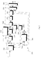
- The invention will now be described, by way of non-limiting example, with reference to the figures of the annexed figures of drawing, wherein:
- Figure 1 has already been described previously;
- Figure 2 shows a first embodiment of a coding device according to the invention; and
- Figure 3 shows a second embodiment of a coding device according to the invention.
- In summary, a block-coding method and a corresponding device for block coding of data are proposed, which envisage detecting in the coding step whether a block currently being coded is liable to generate a mismatch error, and, if so, modifying said current block so as to eliminate the mismatch error.
- To take into account the type of implementation of the coding device, i.e., whether said coding device will be implemented in a purely software way or in a mixed hardware/software way, two different embodiments are proposed, which envisage, respectively:
- resetting the block coefficients to zero; this enables a simple low-power implementation to be obtained, as will be illustrated more clearly hereinafter with reference to Figure 2; and
- incrementing the value of the quantizer in order to prevent the mismatch; this solution, which is illustrated hereinafter with reference to Figure 3, appears to be the best solution in terms of quality and of PSNR (Peak Signal-to-Noise Ratio) values, even though it requires all the blocks of one and the same macroblock to be coded with a higher quantizer value.
- The first embodiment, which contemplates, that is, zeroizing the coefficients of the block before coding, substantially envisages verifying, after the IDCT at the encoder end, whether a zero block is reconstructed from a block that contains some non-zero DCT coefficients. If this occurs, the coding device is configured for forcing to zero a block in terms of Huffman coding.
- Figure 2 shows a coding device that implements said first embodiment.
- Represented, then, in Figure 2 is a coding device, designated as a whole by the
reference number 200, which receives at input the noncompressed-data flow I. Said noncompressed-data flow I is sent at input to a motion-estimator block 210, which generates at output motion vectors VM. The noncompressed-data flow I is sent in parallel to one of the inputs of anadder 212 to be added to the output of aframe memory 280. Saidframe memory 280 has the function of storing the preceding frame to be used for the operations of temporal prediction together with the motion vectors VM. The sum obtained from theadder 212 is sent at input to atransformation module 220, which carries out the DCT. The output of thetransformation module 220 is supplied to aquantization module 230, which applies a quantization according to a quantization parameter QP, which is supplied by a rate-control module 270. The rate-control module 270 operates on the basis of the input signal, i.e., the noncompressed-data flow I, and of the output signal, i.e., a compressed-data flow O, of thecoding device 200, which themodule 270 receives at two appropriate inputs of its own. - Downstream of the
quantization module 230 the signal, constituted by the compressed blocks DB, is sent to an inverse-quantization module 290 and to anIDCT module 295, in order to obtain decompressed frames O' to be supplied to theframe memory 280, after being added to the output of theframe memory 280 in anappropriate adder 214. - The output of the
quantization module 230 is likewise sent to the output of thecoding device 200 through an AC/DC prediction module 235 and a variable-length-coding (VLC)module 240, which adopts VLC techniques and Huffman coding to produce a coded data flow with a good statistical efficiency of compression. The output of theVLC module 240 is sent to amultiplexer 250, together with the motion vectors VM. Set downstream of themultiplexer 250 is abuffer 260, which supplies at output the compressed-data flow O. - The modules so far described and their arrangements are in themselves known to the state of the art regarding coding devices of an MPEG type. However, according to the method proposed, in the coding device described in Figure 2, provided downstream of the
quantization module 230 and upstream of the AC/DC prediction module 235 is a mismatch-control module 1000. Said mismatch-control module 1000 detects the blocks RB reconstructed by theIDCT module 295 and modifies the compressed blocks DB upstream of the coding performed in the AC/DC prediction module 235 and in theVLC module 240, via the operation of zeroizing the DCT coefficients of said compressed blocks DB to be coded, should a zero block be reconstructed from a block containing non-zero DCT coefficients. - The use of said procedure in the mismatch-
control module 1000 imposes some constraints upon implementation of the H/W coding device. In fact, after the quantization performed in thequantization module 230, the data must wait for the results of the inverse quantization and of the IDCT in theblocks DC prediction module 235 there must hence be inserted an additional buffer contained in the mismatch-control module 1000, which leads to an increase in the area dedicated to the chip, an increase in the latency of the data, and a reduction in the parallelism between the computing procedures involved. - A second embodiment of the method proposed overcomes the drawback of having to wait for the results of the inverse quantizations and of the IDCT before coding via the Huffman table, as well as the deterioration in the PSNR values.
- Said second embodiment prevents the mismatch error without requiring any checks on the reconstructed block downstream of the IDCT, since it is based upon the analysis of the SAD (Sum of Absolute Differences) function and the quantizer values of the current block at the coding-device end. Said information is available at the coding-device end because the motion-estimation procedure calculates it in order to identify the motion vectors.
- The ensuing description of said second embodiment of the method proposed comprises two parts. In a first part a general approach to the mismatch error is provided, which is irrespective of the implementation of particular proprietary algorithmic procedures, for example, of a forward DCT, forward quantization, and inverse quantization type.
- Described in the second part is, instead, the treatment of the specific case of the implementation of the MPEG-4-coding procedure. In the treatment that follows the errors due to the finite-precision arithmetic will not be taken into consideration in a first-order approximation. In a second step, shown in the subsequent paragraph, said errors will be considered and a final solution to the problem will be provided.
- As regards infinite arithmetic approximation, by virtue of Parseval's theorem, there is a connection between the energy in the DCT domain and the energy in the space domain.

where x i indicate coefficients in the space domain corresponding to a block in the input data flow I and X i indicate coefficients corresponding to the DCT domain. - It is possible to set in relation the SAD function with the energy:

- The above Equation (2) enables an upper limit to be set to the mismatch error. In fact, if one finds the block that presents the maximum value for the summation

- Assuming that the coefficients in the space domain x i represent the data on the mismatch error, we can write


- Thus, the square of the SAD function is

- Hence, finally, we obtain

- Applying Parseval's theorem, it is possible to set in relation the energy in the space domain with the energy in the DCT domain, so that

where x i are the coefficients in the space domain, whilst Xi are the coefficients in the DCT domain. - Finally, on the basis of the equations given above, it is possible to attempt calculation of the minimum value of the SAD function that enables the mismatch error to be prevented. Said problem can be solved by finding, from among the blocks that produce the mismatch error, the one presenting the maximum value of energy.
- The impact of the finite-precision arithmetic must be considered in the light of the fact that the previous solution, in particular with reference to Equation (7) has been obtained considering the validity of Parseval's theorem, which is, however, only proven when an infinite precision of calculation is assumed.
- In an implementation of a real type, the DCT is calculated using finite-precision arithmetic, so that it is necessary to take into account that the Parseval relation becomes

where E is the block energy. - In the above calculation the SAD function in the space domain and the energy in the DCT domain are calculated, so that the FDCT (Finite Discrete Cosine Transform) error must be appropriately studied.
- Assuming the finite-precision calculations as an error ε that affects each DCT coefficient, we can write the relation

where X i indicates the ideal value of the DCT coefficient, X̅ i is the DCT coefficient obtained with the finite-precision arithmetic and εi is the error. - Assuming that X i , ε i ∈∀i, we have


- Given a maximum error ε x = max(ε i , i = 1,...,64), we obtain

- The relation with the SAD function will be

- In the real case, to be able to exploit the solution described above, it is necessary to take into account the particular implementation of the IDCT.
- Once the real implementation of the encoder has been fixed, it is thus sufficient to identify the block having maximum SAD that causes mismatch error and to use said value as upper limit Th for the equation 12. It is possible to identify also a minimum value Qpmin of the quantization parameter QP above which the mismatch does not occur. This makes it possible to avoid that blocks presenting a value assumed by the SAD function (designated in what follows as value S) lower than the threshold identified will be considered as being affected by mismatch errors when in actual fact they are not.
- Consequently, the pseudocode that describes the operation of detection of the mismatch, on the basis of the value calculated in this example of embodiment, would be:
If(QP<=QPmin && SAD<Th)
MismatchWarning () ;
where the function MismatchWarning() is the function that handles the modification. - The function MismatchWarning() corresponding to the modification operations can have two possible embodiments that envisage the operations either of:
- resetting the block to be coded; or else of
- incrementing the value of the quantization step QP=
QPmin+ 1. - The first solution is simple to implement and, moreover, the blocks that follow can be turned off, with a consequent lower energy consumption.
- The second solution is simple to implement and ensures a higher quality in so far as some of the blocks detected as being affected by mismatch, with QP=
QPmin+ 1, will certainly not in fact be affected. - The pseudocode corresponding to the function MismatchWarning() for the first solution that envisages block resetting is:

- The index b indicates the block B that is each time examined as regards SAD and QP values, i.e., the current block CB. dct_b, iq_b, recon_b and VLC represent variables corresponding to application of DCTs, quantizations, inverse quantizations and VLC coding to the blocks B at input, in_b, or at output, out_b.
- An example of procedure in pseudocode comprising the function MismatchWarning() for the second solution, with the strategy of incrementation of the quantization step QP, is:

- Figure 3 shows a possible implementation, in a
coding device 300, of the second solution for controlling mismatch described above, with the strategy of incrementation of the quantization step QP. In Figure 3, the modules having functions similar to the ones already described with reference to Figure 2 are designated by the same reference numbers. - In Figure 3, a mismatch-
control block 1100 is inserted so as to receive from themotion estimator 210 at one input thereof macroblocks MB derived from the noncompressed-data flow I, and at another input thereof values S of the corresponding SAD function; at a third input, the mismatch-control block 1100 receives the value of the quantization step QP applied in the compression of the current macroblock from the rate-control module 270. - At output, the mismatch-
control module 1100 supplies a macroblock to be coded MB' to theadder 212, and a minimum quantizer value Qmin to the rate-control module 270. - The function MismatchWarning() fixes the minimum value of the quantization step QP in order to increase the PSNR. Consequently, the procedure can, for example, be represented, in terms of program instructions in pseudocode, also as:

- It should be noted that, in this case, the direct DCT, the quantization, the inverse quantization, and the inverse DCT can be avoided, with a lower energy consumption.
- The major advantages of this type of embodiment are the following:
- the loop-coding device does not require any modifications;
- the block is coded just once;
- multitasking is allowed, so that each block can process different macroblocks (i.e., the quantization block can process a macroblock, whilst the DCT block can process a subsequent macroblock at the same time);
- a lower-limit constraint is set on the quantizer value only for critical macroblocks;
- the embodiment is very simple to implement and does not require an excessive use of resources.
- In actual fact, not all the blocks that present a value of the SAD function lower than the value established will give rise to mismatch. Using this procedure, a lower limit is set on the quantizer value also for these macroblocks.
- Consequently, without prejudice to the principle of the invention, the details of implementation and the embodiments may vary, even significantly, with respect to what is described and illustrated herein, purely by way of non-limiting example, without thereby departing from the scope of the invention, as defined in the ensuing claims.
- For example, as regards the procedure of identification of the values of SAD function and of minimum quantization parameter, it is possible to obtain said values even in another way, for example, by means of an exhaustive procedure that tries all the combinations of values, according to a so-called 'brute force' approach.
Claims (19)
- A method for block coding of a flow (I) of data, in particular video data, via a compression operation (100; 200; 300) which comprises: applying to input-data blocks (B, CB; MB) in said data flow (I) a discrete-cosine-transform (DCT) operation (120; 220) and a quantization operation (130; 230) to produce compressed-data blocks (DB); subjecting said compressed-data blocks (DB) to a coding operation (235, 240) to obtain compressed output flows (O); and moreover applying an inverse-quantization operation (190; 290) and an inverse-discrete-cosine-transform (IDCT) operation (195; 295) on said compressed-data blocks (DB) to obtain reconstructed blocks (RB), said method being characterized in that it comprises controlling (1000; 1100) generation of mismatch errors from said input-data blocks (B, CB; MB) via the operations of:- detecting from said input-data blocks (B, CB; MB) and said compressed-data blocks (DB) data blocks (DB; MB) that are liable to cause mismatch errors; and- modifying said blocks (DB; MB) that are liable to cause mismatch errors prior to said coding operation (235, 240).
- The method according to Claim 1, characterized in that said operation of detecting (1000) blocks that are liable to cause mismatch errors (DB) comprises verifying whether a block (RB) reconstructed from a compressed-data block (DB) is a zero block and whether a corresponding current block (CB) from among the input-data blocks (B, CB) is a non-zero block, and said modification operation comprises rendering said compressed-data block (DB) a zero block.
- The method according to Claim 2, characterized in that it comprises the operation of storing temporarily the results of said quantization operation (230) during said detection operation (1000).
- The method according to Claim 1, characterized in that said detection operation (1100) comprises evaluating a value (S) of SAD (Sum of Absolute Differences) function and a value (QP) of a quantization step corresponding to a current input-data block (MB).
- The method according to Claim 4, characterized in that said detection operation (1100) comprises evaluating whether said value (QP) of quantization step differs from a minimum value (QPmin) that can cause mismatch.
- The method according to Claim 4 or Claim 5, characterized in that said detection operation (1100) comprises calculating the minimum value of the SAD function that is able to prevent the mismatch error and comparing said value (S) of SAD function of blocks belonging to the input data (I) with said minimum value.
- The method according to any one of Claims 4 to 6, characterized in that said modification operation comprises zeroizing the current input-data block (MB) and turning off the subsequent data blocks.
- The method according to any one of Claims 4 to 6, characterized in that said modification operation comprises fixing a lower limit to said value of the quantization step (QP) on the basis of the result of said evaluation operation at an incremented value (QPmin+1).
- The method according to one or more of the preceding claims, characterized in that said compression operation (200; 300) is performed in accordance with one of the standards MPEG-1, MPEG-2, MPEG-4 and H.263.
- A device for block coding of a flow (I) of data, in particular video data, of the type that comprises a module (100; 200; 300) for performing a compression on input-data blocks (B, CB, MB) in said data flow (I), which comprises: a module for performing a discrete cosine transform (DCT) (120; 220) and a quantization module (130; 230), which produce compressed-data blocks (DB); a coding module (235, 240) operating on said compressed-data blocks (DB); and, in addition, an inverse-quantization module (190, 290) and an inverse-discrete-cosine-transform (IDCT) module (195; 295) operating on said compressed-data blocks (DB) to obtain reconstructed blocks (RB),
said device being characterized in that it further comprises a module (1000; 1100) for controlling generation of mismatch errors configured for detecting, from the input-data blocks (B, CB, MB) and the compressed-data blocks (DB), data blocks (DB; MB) that are liable to cause mismatch errors and for modifying said data blocks (DB; MB) that are liable to cause mismatch errors, said module (1000; 1100) for controlling generation of mismatch errors being set upstream of said coding module (235, 240). - The device according to Claim 10, characterized in that said module (1000; 1100) for controlling generation of mismatch errors is connected to the output of said IDCT module (295) so as to verify whether a block (RB) reconstructed from a compressed-data block (DB) is a zero block and whether a corresponding block (DB) from among the input-data blocks (B, CB; MB) is a non-zero block, and in that said module (1000) for controlling generation of mismatch errors is moreover configured for rendering said compressed-data block (DB) a zero block.
- The device according to Claim 11,
characterized in that said module (1000) for controlling generation of mismatch errors comprises temporary-memory means for storing data at output from said quantization module (230). - The device according to Claim 10, characterized in that said module (1100) for controlling generation of mismatch errors receives at input a current block (MB) of the input data flow (I), a value (S) of SAD (Sum of Absolute Differences) function corresponding to said current block (MB) from a motion-estimation module (210), and a value (QP) of quantization step corresponding to said current block (MB) from a rate-control module (270), and in that said module (1100) for controlling generation of mismatch errors is configured for enabling, according to said value (S) of SAD function and said value (QP) of quantization step, execution of said operation of modifying said blocks (MB) that are liable to cause mismatch errors.
- The device according to Claim 13, characterized in that said mismatch-control module (1100) is configured for evaluating whether said value (QP) of the quantization step is higher than the minimum value that will produce mismatch error.
- The device according to Claim 13 or Claim 14, characterized in that said module (1100) for controlling generation of mismatch errors is configured for calculating the minimum value of the SAD function that enables the mismatch error to be prevented and compare said value (S) of SAD function of the current block (MB) with said minimum value.
- The device according to at least one of Claims 13 to 15, characterized in that said module (1100) for controlling generation of mismatch errors is configured for zeroizing the block (MB) that is liable to cause mismatch errors and turning off the subsequent blocks.
- The device according to at least one of Claims 13 to 15, characterized in that said mismatch-control module (1100) is configured for executing said modification operation by calculating an incremented value of the quantization step (Qmin) and supplying said incremented value of the quantization step (Qmin) to said rate-control module (270).
- The device according to one or more of Claims 10 to 16, characterized in that said module for performing a compression (200; 300) operates in accordance with one of the standards MPEG-1, MPEG-2, MPEG-4 and H.263.
- A computer-program product loadable into the memory of at least one computer and comprising software code portions for implementing the method according to any one of Claims 1 to 9.
Applications Claiming Priority (1)
| Application Number | Priority Date | Filing Date | Title |
|---|---|---|---|
| IT000764A ITTO20040764A1 (en) | 2004-11-05 | 2004-11-05 | PROCEDURE FOR CODIFYING A FLOW OF DATA, IN PARTICULAR VIDEO, RELATIVE DATA, RELATIVE DEVICE AND IT PRODUCT. |
Publications (2)
| Publication Number | Publication Date |
|---|---|
| EP1667461A2 true EP1667461A2 (en) | 2006-06-07 |
| EP1667461A3 EP1667461A3 (en) | 2010-12-01 |
Family
ID=36201524
Family Applications (1)
| Application Number | Title | Priority Date | Filing Date |
|---|---|---|---|
| EP05110313A Withdrawn EP1667461A3 (en) | 2004-11-05 | 2005-11-03 | A method for block coding of a flow of data, in particular video data, and corresponding device and computer-program product |
Country Status (3)
| Country | Link |
|---|---|
| US (1) | US7974483B2 (en) |
| EP (1) | EP1667461A3 (en) |
| IT (1) | ITTO20040764A1 (en) |
Families Citing this family (9)
| Publication number | Priority date | Publication date | Assignee | Title |
|---|---|---|---|---|
| US20070162531A1 (en) * | 2006-01-12 | 2007-07-12 | Bhaskar Kota | Flow transform for integrated circuit design and simulation having combined data flow, control flow, and memory flow views |
| US8121189B2 (en) * | 2007-09-20 | 2012-02-21 | Microsoft Corporation | Video decoding using created reference pictures |
| US9848209B2 (en) * | 2008-04-02 | 2017-12-19 | Microsoft Technology Licensing, Llc | Adaptive error detection for MPEG-2 error concealment |
| US9788018B2 (en) * | 2008-06-30 | 2017-10-10 | Microsoft Technology Licensing, Llc | Error concealment techniques in video decoding |
| US9924184B2 (en) | 2008-06-30 | 2018-03-20 | Microsoft Technology Licensing, Llc | Error detection, protection and recovery for video decoding |
| US20100065343A1 (en) * | 2008-09-18 | 2010-03-18 | Chien-Liang Liu | Fingertip Touch Pen |
| US9131241B2 (en) * | 2008-11-25 | 2015-09-08 | Microsoft Technology Licensing, Llc | Adjusting hardware acceleration for video playback based on error detection |
| US8340510B2 (en) * | 2009-07-17 | 2012-12-25 | Microsoft Corporation | Implementing channel start and file seek for decoder |
| EP2485488B1 (en) * | 2011-02-02 | 2017-04-12 | Nagravision S.A. | A media decoder and a decoding method allowing for the media decoder to be traced |
Citations (1)
| Publication number | Priority date | Publication date | Assignee | Title |
|---|---|---|---|---|
| US6215425B1 (en) * | 1992-02-19 | 2001-04-10 | Netergy Networks, Inc. | Deblocking filter for encoder/decoder arrangement and method with divergence reduction |
Family Cites Families (4)
| Publication number | Priority date | Publication date | Assignee | Title |
|---|---|---|---|---|
| JPH05276500A (en) * | 1991-07-19 | 1993-10-22 | Sony Corp | Moving image coding and decoding device |
| US5604502A (en) * | 1994-03-21 | 1997-02-18 | Lucent Technologies Inc. | Motion video compression system with inverse discrete cosine transform mismatch control |
| US6275527B1 (en) * | 1998-01-14 | 2001-08-14 | Conexant Systems, Inc. | Pre-quantization in motion compensated video coding |
| JP3960451B2 (en) * | 2000-03-06 | 2007-08-15 | Kddi株式会社 | Scene characteristic detection type moving picture coding apparatus |
-
2004
- 2004-11-05 IT IT000764A patent/ITTO20040764A1/en unknown
-
2005
- 2005-11-03 EP EP05110313A patent/EP1667461A3/en not_active Withdrawn
- 2005-11-04 US US11/267,077 patent/US7974483B2/en active Active
Patent Citations (1)
| Publication number | Priority date | Publication date | Assignee | Title |
|---|---|---|---|---|
| US6215425B1 (en) * | 1992-02-19 | 2001-04-10 | Netergy Networks, Inc. | Deblocking filter for encoder/decoder arrangement and method with divergence reduction |
Also Published As
| Publication number | Publication date |
|---|---|
| US20060098732A1 (en) | 2006-05-11 |
| US7974483B2 (en) | 2011-07-05 |
| ITTO20040764A1 (en) | 2005-02-05 |
| EP1667461A3 (en) | 2010-12-01 |
Similar Documents
| Publication | Publication Date | Title |
|---|---|---|
| US8175404B2 (en) | Method and device for estimating image quality of compressed images and/or video sequences | |
| Lengwehasatit et al. | Scalable variable complexity approximate forward DCT | |
| US20050053288A1 (en) | Bitstream-controlled post-processing filtering | |
| Xin et al. | Converting DCT coefficients to H. 264/AVC transform coefficients | |
| US8000393B2 (en) | Video encoding apparatus and video encoding method | |
| EP2373049A1 (en) | Video quality measurement | |
| EP0577350B1 (en) | A video signal coding and decoding apparatus with an adaptive edge enhancement filter | |
| US6717988B2 (en) | Scalable MPEG-2 decoder | |
| PL173287B1 (en) | Method of and apparatus for preventing rounding errors during reversed transformation of coefficients of a transform representing a moving image signal | |
| US11394958B2 (en) | Image encoding device, image decoding device and program | |
| KR20060060000A (en) | Video Encoding and Decoding Methods and Apparatuses | |
| US20060274959A1 (en) | Image processing to reduce blocking artifacts | |
| US20170041605A1 (en) | Video encoding device and video encoding method | |
| US7974483B2 (en) | Method and corresponding device for block coding data | |
| KR20030086076A (en) | Filtering method for removing block artifacts and/or ringing noise and apparatus therefor | |
| US6859815B2 (en) | Approximate inverse discrete cosine transform for scalable computation complexity video and still image decoding | |
| US20040028127A1 (en) | Method and apparatus for reducing computational complexity in video encoders | |
| Lee et al. | A CU-level rate and distortion estimation scheme for RDO of hardware-friendly HEVC encoders using low-complexity integer DCTs | |
| US10104389B2 (en) | Apparatus, method and non-transitory medium storing program for encoding moving picture | |
| US20070147505A1 (en) | Processing a compressed video signal | |
| US20220337837A1 (en) | Architecture for rate estimation in video coding | |
| US20190089955A1 (en) | Image encoding method, and image encoder and image decoder using same | |
| US9131246B2 (en) | Detecting artifacts in quantization noise in images compresses using discrete cosine transforms | |
| US20130329792A1 (en) | Method and device for optimizing the compression of a video stream | |
| EP1819171A2 (en) | Information processing apparatus |
Legal Events
| Date | Code | Title | Description |
|---|---|---|---|
| PUAI | Public reference made under article 153(3) epc to a published international application that has entered the european phase |
Free format text: ORIGINAL CODE: 0009012 |
|
| AK | Designated contracting states |
Kind code of ref document: A2 Designated state(s): AT BE BG CH CY CZ DE DK EE ES FI FR GB GR HU IE IS IT LI LT LU LV MC NL PL PT RO SE SI SK TR |
|
| AX | Request for extension of the european patent |
Extension state: AL BA HR MK YU |
|
| RAP1 | Party data changed (applicant data changed or rights of an application transferred) |
Owner name: STMICROELECTRONICS SRL |
|
| PUAL | Search report despatched |
Free format text: ORIGINAL CODE: 0009013 |
|
| AK | Designated contracting states |
Kind code of ref document: A3 Designated state(s): AT BE BG CH CY CZ DE DK EE ES FI FR GB GR HU IE IS IT LI LT LU LV MC NL PL PT RO SE SI SK TR |
|
| AX | Request for extension of the european patent |
Extension state: AL BA HR MK YU |
|
| 17P | Request for examination filed |
Effective date: 20110531 |
|
| AKX | Designation fees paid |
Designated state(s): DE FR GB IT |
|
| 17Q | First examination report despatched |
Effective date: 20110719 |
|
| RAP1 | Party data changed (applicant data changed or rights of an application transferred) |
Owner name: STMICROELECTRONICS SRL |
|
| GRAP | Despatch of communication of intention to grant a patent |
Free format text: ORIGINAL CODE: EPIDOSNIGR1 |
|
| STAA | Information on the status of an ep patent application or granted ep patent |
Free format text: STATUS: THE APPLICATION IS DEEMED TO BE WITHDRAWN |
|
| 18D | Application deemed to be withdrawn |
Effective date: 20130409 |