EP1667048A1 - Antennenanordnung sowie eine Tiererkennungsvorrichtung mit einer Antennenanordnung - Google Patents
Antennenanordnung sowie eine Tiererkennungsvorrichtung mit einer Antennenanordnung Download PDFInfo
- Publication number
- EP1667048A1 EP1667048A1 EP05025823A EP05025823A EP1667048A1 EP 1667048 A1 EP1667048 A1 EP 1667048A1 EP 05025823 A EP05025823 A EP 05025823A EP 05025823 A EP05025823 A EP 05025823A EP 1667048 A1 EP1667048 A1 EP 1667048A1
- Authority
- EP
- European Patent Office
- Prior art keywords
- sections
- antenna
- antenna arrangement
- animal
- pair
- Prior art date
- Legal status (The legal status is an assumption and is not a legal conclusion. Google has not performed a legal analysis and makes no representation as to the accuracy of the status listed.)
- Granted
Links
- 241001465754 Metazoa Species 0.000 title claims abstract description 60
- 238000001514 detection method Methods 0.000 claims description 12
- 241000283707 Capra Species 0.000 description 3
- 241001494479 Pecora Species 0.000 description 3
- 241000283690 Bos taurus Species 0.000 description 2
- 241000282836 Camelus dromedarius Species 0.000 description 2
- 230000001419 dependent effect Effects 0.000 description 2
- 238000011161 development Methods 0.000 description 2
- 230000018109 developmental process Effects 0.000 description 2
- 238000004804 winding Methods 0.000 description 2
- 238000003491 array Methods 0.000 description 1
- 235000013365 dairy product Nutrition 0.000 description 1
- 230000007423 decrease Effects 0.000 description 1
- 210000002249 digestive system Anatomy 0.000 description 1
- 230000000694 effects Effects 0.000 description 1
- 244000144980 herd Species 0.000 description 1
- 230000006698 induction Effects 0.000 description 1
- 238000004519 manufacturing process Methods 0.000 description 1
- 230000001105 regulatory effect Effects 0.000 description 1
- 238000005303 weighing Methods 0.000 description 1
Images


Classifications
-
- A—HUMAN NECESSITIES
- A01—AGRICULTURE; FORESTRY; ANIMAL HUSBANDRY; HUNTING; TRAPPING; FISHING
- A01K—ANIMAL HUSBANDRY; AVICULTURE; APICULTURE; PISCICULTURE; FISHING; REARING OR BREEDING ANIMALS, NOT OTHERWISE PROVIDED FOR; NEW BREEDS OF ANIMALS
- A01K11/00—Marking of animals
- A01K11/006—Automatic identification systems for animals, e.g. electronic devices, transponders for animals
Definitions
- the subject of the present invention relates to an antenna arrangement for transmitting and / or receiving a signal to and from a transponder carried by an animal, as well as to an animal recognition device having such an antenna arrangement.
- identification transponders For identification of animals, especially in dairy farms, electronic systems are used.
- the animals to be identified are equipped with identification means.
- identification means Usually these are transponders.
- the transponders can be attached, for example, as ear tags to animals.
- identification means are implanted subcutaneously.
- identification transponders are used in the digestive system of the animal.
- the transponders may be passive or active transponders. Passive transponders do not have their own energy source. Such transponders receive induced electrical energy by receiving appropriate electromagnetic energy emitted by an antenna mounted at the locations where identification is to be achieved.
- antennas are provided, for example, in the area of a feeding place, a milking station, a weighing station.
- the identification of animals also serves for the sorting of animals, so that antennas are also arranged in the area of sorting devices.
- this can also transmit a plurality of different signal contents.
- This may be, for example, an identification signal and / or signals related to the physical characteristics of the animal.
- transponders are known which also transmit the temperature of the animal. For the detection of heat in milk-emitting animals, the activity of the animal is determined and transmitted by means of the transponder as a signal to the antenna.
- Active transponders have their own energy sources, so that these transponders can transmit the corresponding signals to the antenna without any energy being induced.
- Antenna arrays are used to transmit and / or receive a signal to or from a transponder carried by an animal.
- Such antenna arrangements are known, for example, from WO 97/32468 or from WO 97/08646.
- WO 97/32468 describes an antenna arrangement with two antennas, which are essentially U-shaped. They each have two vertically extending portions which are interconnected by a horizontally extending connecting portion. These antennas are positioned adjacent to the passage through which the animals are led.
- the present invention is based on the object of an antenna arrangement for transmitting and / or receiving a signal to a or from a transponder carried by an animal, so on that detection reliability is increased.
- the antenna arrangement according to the invention for transmitting and / or receiving a signal to and from a transponder which is carried by an animal has at least one antenna.
- the antenna has at least one pair of spaced and interconnected portions located in a common area, particularly in a common plane. As viewed in the sections, a distance between sections is variable.
- This embodiment of the antenna arrangement according to the invention generates a spatial field that is inhomogeneous with respect to its orientation. This strong inhomogeneity of the field has the advantage that an identification is achieved substantially independently of an orientation of a transponder. Particularly in the case of an antenna arrangement, by means of which electrical energy is induced for the transponder, it is induced sufficient electrical energy in the region of a detection zone which is determined by the field.
- the surface in which the at least one pair of spaced-apart and interconnected portions lies is preferably flat. Depending on the application, the surface may also be curved. Preferred is an embodiment in which the at least one pair is arranged in a vertical or horizontal plane. If the antenna arrangement according to the invention is used in conjunction with an animal recognition device, then this is preferably arranged so that the surface is substantially parallel to one of the side surfaces of a passage.
- the orientation and the shape of the field which the antenna generates can be influenced by suitable configurations of the sections as well as the courses of the sections relative to each other.
- the distance in the longitudinal direction of the sections changes continuously over at least a partial length of the sections.
- At least one section is substantially rectilinear.
- an embodiment in which all sections of the antenna are rectilinear is preferred.
- Such an embodiment has the advantage that the manufacture of the antenna is relatively simple. This is particularly important if the antenna is to be fixed to a support structure, which is, for example, support plates.
- the antenna arrangement For an even further increase in the detection reliability of transponders that are carried by animals, it is proposed according to a still further advantageous embodiment of the antenna arrangement that at least two pairs are provided, each having sections that are connected to each other in a common area and spaced from each other are.
- the detection range can be increased.
- the detection reliability of the transponder and the induction of energy in passive transponders can be increased even further by providing two surfaces in each of which a pair of sections spaced apart from one another and connected to one another in the respective surface are provided.
- the surfaces intersect.
- the surfaces can also intersect at right angles, so that, for example, one antenna is provided in one vertical surface and another antenna is provided in a horizontal surface.
- the at least one antenna is formed by at least one coil.
- the antenna is formed by a plurality of coils, wherein a co-directional winding of the coil is preferred.
- the present invention is also based on the object, so on an animal detection device with a passage and an arranged in the passage area antenna arrangement for transmitting and / or receiving a signal to or from a transponder, which is carried by an animal to form in that a more reliable animal identification or animal identification is achieved.
- the device according to the invention has a passage and an antenna arrangement arranged in the region of the passage.
- the antenna arrangement serves to transmit and / or receive a signal to or from a transponder which is carried by an animal.
- the antenna assembly has at least one antenna.
- This antenna has at least one pair of spaced-apart and interconnected portions lying in a common area.
- the arrangement of the sections is selected such that viewed in a longitudinal direction of the sections, a distance between the sections is variable.
- the animals that are provided with a transponder can be cows, buffaloes, dromedaries, mares or smaller milk-yielding animals such as, in particular, sheep or goats.
- the animal recognition device according to the invention is particularly suitable for the detection of transponders that are carried by sheep or goats.
- an embodiment of an animal identification device in which the sections are arranged in a substantially vertical surface of the passage.
- the sections preferably extend to near the bottom of the passage, so that even animals which have, for example, a transponder as ear tag, are recognized by the lowered head.
- the at least one pair is designed such that the spacing of the sections increases from a bottom of the passage to the top.
- an antenna or an antenna are provided in each case.
- the distance in the longitudinal direction of the sections changes continuously over at least a partial length of the sections.
- an embodiment of the animal recognition device is particularly preferred, in which at least one of the sections is substantially rectilinear.
- the animal recognition device In order to further improve the recognition reliability or the recognition rate, it is proposed according to a still further advantageous refinement of the animal recognition device that at least two pairs of sections spaced from one another and connected to one another are provided in at least one common area. This will further improve the recognition rate.
- the antenna may be formed by at least one coil.
- the animal recognition device has further numerous advantages. It is suitable for detecting milk-emitting animals, which are z. B. can be cows, goats, sheep, mares, dromedaries, yaks or the like.
- the animal recognition device can be connected to a corresponding control and regulating device of a milking device.
- the data determined by the animal recognition device be transmitted to a herd management system.
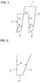
- FIG. 1 shows schematically and in perspective an antenna arrangement for transmitting and / or receiving a signal to and from a transponder carried by an animal.
- the antenna arrangement has an antenna 1.
- the antenna has a first pair of spaced-apart and interconnected ones in one common surface lying sections 2, 3.
- the sections 2, 3 are connected in the illustrated embodiment by a substantially horizontally extending portion 6. Viewed in the longitudinal direction of the sections, the distance between the sections 2, 3 changes. As viewed from the horizontal section 6, the distance in the longitudinal direction of the sections 2, 3 increases.
- sections 4, 5 are provided in a plane parallel to the surface in which the sections 2, 3 lie.
- the sections 4, 5 are connected to each other by a substantially horizontally extending portion 6.
- the sections 4, 5 form a second pair of sections of the antenna 1.
- the antenna 1 is formed substantially symmetrically.
- the distance A in the longitudinal direction of the sections changes continuously.
- the sections 2 to 5 are formed in the illustrated embodiment is substantially rectilinear. This is not mandatory.
- the antenna 1 is formed by a coil. There is also the possibility that the antenna is formed by a plurality of coils. In such an embodiment, a co-directional winding of the coils is preferred.
- the antenna arrangement according to the invention allows numerous different configurations. By way of example, some possible configurations of the antenna arrangement are shown in FIGS. 3 to 6.
- Figure 3 shows an antenna in a configuration in which two pairs of sections are provided.
- the first pair is formed by the sections 7, 8, wherein the sections 7, 8 viewed in the longitudinal direction of the sections have a distance A which is variable.
- the sections 7, 8 are connected by a section 9 with each other.
- the portion 7 is substantially perpendicular, wherein the portion 8 is inclined relative to a vertical.
- the second pair is formed by the sections 11, 12. Also in sections 11, 12 the distance changes. From a section 13 connecting the sections 11, 12, viewed from the distance B increases.
- the illustration according to FIG. 3 shows that the section 12 extends essentially vertically, the section 11 being inclined toward the section 8. The inclination angles of the first pair and the second pair are different.
- the first pair and second pair or the portion 8 and the portion 11 are connected by a portion 10 with each other.
- sections 7 and 12 are substantially perpendicular. These may also be inclined to a vertical when the antenna is positioned in a vertical plane.
- the antenna arrangement can be designed so that it is for example V- or W-shaped.
- FIG. 4 shows a still further embodiment of an antenna arrangement.
- two pairs of sections are shown.
- a first pair is formed by the sections 7, 8, while the second pair are formed by the sections 11, 12.
- the pairs are offset from each other.
- Figure 4 shows an embodiment in which the sections 7, 12 and the sections 8 and 11 are each substantially parallel to each other, but this is not absolutely necessary.
- FIG. Sections 7, 8 are provided in which the distance A increases in the longitudinal direction of the section 7 as viewed from a section 9, while the distance B of the pair of sections 11, 12 decreases from a section 13 in the longitudinal direction of the section 12.
- FIG. 6 shows a sawtooth configuration of an antenna.
- the course of the distances A, B of the pairs is preferably equal, so that the antenna is constructed substantially symmetrically.
- FIGs 7 and 8 show schematically an animal detection device with a passage 14.
- the passage 14 is laterally bounded by a struts 15, 16 formed, in particular a non-metallic, scaffold.
- An antenna array is provided on the scaffold for transmitting and / or receiving a signal to and from a transponder carried by an unillustrated animal.
- the antenna arrangement has an antenna 1, which is constructed according to the embodiment of FIG. When animals are being carried in the direction of the arrow in FIG. 8, animal identification is carried out.
Landscapes
- Life Sciences & Earth Sciences (AREA)
- Environmental Sciences (AREA)
- Birds (AREA)
- Zoology (AREA)
- Animal Husbandry (AREA)
- Biodiversity & Conservation Biology (AREA)
- Radar Systems Or Details Thereof (AREA)
- Details Of Aerials (AREA)
- Burglar Alarm Systems (AREA)
Abstract
Description
- Der Gegenstand der vorliegenden Erfindung bezieht sich auf eine Antennenanordnung zum Senden und/oder Empfangen eines Signals zu einem bzw. von einem Transponder, der von einem Tier getragen wird, sowie auf eine Tiererkennungsvorrichtung mit einer solchen Antennenanordnung.
- Zur Identifikation von Tieren, insbesondere in Milchviehaltungsbetrieben werden elektronische Systeme verwendet. Die zu identifizierenden Tiere sind mit Identifikationsmitteln ausgestattet. Gewöhnlich handelt es sich hierbei um Transponder. Die Transponder können beispielsweise als Ohrmarken an Tieren befestigt sein. Es ist auch bekannt, dass Identifizierungsmittel subkutan implantiert werden. Darüber hinaus ist bekannt, dass Identifizierungs-Transponder in das Verdauungssystem des Tieres eingesetzt werden.
- Bei den Transpondern kann es sich um passive oder aktive Transponder handeln. Passive Transponder verfügen über keine eigene Energiequelle. Solche Transponder erhalten induzierte elektrische Energie durch Empfangen geeigneter elektromagnetischer Energie, die durch eine Antenne emittiert wird, die an den Positionen angebracht sind, an denen eine Identifikation erreicht werden soll.
- Es ist daher bekannt, dass Antennen beispielsweise im Bereich eines Fütterungsplatzes, einer Melkstation, einer Wiegestation vorgesehen werden. Die Identifikation von Tieren dient auch zur Sortierung von Tieren, so dass Antennen auch im Bereich von Sortiereinrichtungen angeordnet werden. In Abhängigkeit vom Aufbau des Transponders kann dieser auch eine Mehrzahl von unterschiedlichen Signalinhalten übermitteln. Hierbei kann es sich beispielsweise um ein Identifikationssignal und/oder Signale, die im Zusammenhang mit den physischen Eigenschaften des Tieres stehen, handeln. So sind beispielsweise Transponder bekannt, die auch die Temperatur des Tieres übermitteln. Zur Brunsterkennung bei Milch abgebenden Tieren wird auch die Aktivität des Tieres bestimmt und mittels des Transponders als Signal an die Antenne übermittelt.
- Aktive Transponder verfügen über eigene Energiequellen, so dass diese Transponder die entsprechenden Signale, ohne dass Energie induziert wird an die Antenne übermitteln können.
- Zum Senden und/oder Empfangen eines Signals zu einem bzw. von einem Transponder der von einem Tier getragen wird, werden Antennenanordnungen verwendet. Solche Antennenanordnungen sind beispielsweise durch die WO 97/32468 oder durch die WO 97/08646 bekannt. Die WO 97/32468 beschreibt eine Antennenanordnung mit zwei Antennen, die im Wesentlichen U-förmig ausgebildet sind. Sie weisen jeweils zwei vertikal verlaufende Abschnitte auf, die durch einen horizontal verlaufenden Verbindungsabschnitt miteinander verbunden sind. Diese Antennen sind benachbart zum Durchgang, durch den die Tiere geführt werden, positioniert.
- Problematisch bei derartigen Antennen ist, dass die Position eines Transponders hinsichtlich der Orientierung, der Höhe und dem Abstand zur Antenne erheblichen Schwankungen unterliegen kann. Hierdurch bedingt kann es zu Schwierigkeiten bei der Tieridentifikation kommen. Dieses Problem kann noch verschärft auftreten, wenn eine Identifikation im Durchlauf erfolgen soll.
- Hiervon ausgehend liegt der vorliegenden Erfindung die Aufgabe zu Grunde eine Antennenanordnung zum Senden und/oder Empfangen eines Signals zu einem bzw. von einem Transponder, der von einem Tier getragen wird, so weiter zu bilden, dass eine Erkennungssicherheit erhöht wird.
- Diese Aufgabe wird erfindungsgemäß durch eine Antennenanordnung mit den Merkmalen des Anspruchs 1 gelöst. Vorteilhafte Weiterbildungen und Ausgestaltungen der Antennenanordnung sind Gegenstand der abhängigen Ansprüche.
- Die erfindungsgemäße Antennenanordnung zum Senden und/oder Empfangen eines Signals zu einem bzw. von einem Transponder der von einem Tier getragen wird, weist wenigstens eine Antenne auf. Die Antenne hat wenigstens ein Paar von im Abstand und miteinander verbundenen, in einer gemeinsamen Fläche, insbesondere in einer gemeinsamen Ebene liegende Abschnitte. In Richtung der Abschnitte betrachtet ist ein Abstand zwischen den Abschnitten veränderlich. Durch diese erfindungsgemäße Ausgestaltung der Antennenanordnung wird ein räumliches Feld erzeugt, dass inhomogen in Bezug auf seine Orientierung ausgebildet ist. Diese starke Inhomogenität des Feldes hat den Vorteil, dass im Wesentlichen unabhängig von einer Orientierung eines Transponders eine Identifikation erreicht wird. Insbesondere bei einer Antennenanordnung, durch welche dem Transponder elektrische Energie induziert wird, wird diese im Bereich einer Erkennungszone, die durch das Feld bestimmt wird, eine ausreichende elektrische Energie induziert.
- Die Fläche, in der das wenigstens eine Paar von im Abstand zueinander und miteinander verbundenen Abschnitte liegt, ist vorzugsweise eben. In Abhängigkeit vom Anwendungsfall kann die Fläche auch gekrümmt sein. Bevorzug ist eine Ausbildung, bei der das wenigstens eine Paar in einer vertikalen oder horizontalen Ebene angeordnet ist. Wird die erfindungsgemäße Antennenanordnung in Verbindung mit einer Tiererkennungseinrichtung verwendet, so ist diese vorzugsweise so angeordnet, dass die Fläche im wesentlichen parallel zu einer der Seitenflächen eines Durchgangs ist.
- Die Orientierung und die Form des Feldes, welches die Antenne erzeugt, kann durch geeignete Ausgestaltungen der Abschnitte sowie der Verläufe der Abschnitte relativ zueinander beeinflusst werden. Um Bereiche des Feldes zu vermeiden, in denen das Antennenfeld geschwächt wird, wird vorgeschlagen, dass sich der Abstand in Längsrichtung der Abschnitte über wenigstens eine Teillänge der Abschnitte stetig verändert.
- Gemäß einer noch weiteren vorteilhaften Antennenanordnung wird vorgeschlagen, dass wenigstens ein Abschnitt im Wesentlichen geradlinig ausgebildet ist. Bevorzugt ist dabei eine Ausgestaltung, bei der sämtliche Abschnitte der Antenne geradlinig ausgebildet sind. Eine solche Ausgestaltung hat den Vorteil, dass die Herstellung der Antenne relativ einfach ist. Dies hat insbesondere dann Bedeutung, wenn die Antenne an einer Tragekonstruktion, bei der es sich beispielsweise um Tragplatten handelt, festgelegt werden soll.
- Zu einer noch weiteren Erhöhung der Erkennungssicherheit von Transpondern, die von Tieren getragen werden, wird gemäß einer noch weiteren vorteilhaften Ausgestaltung der Antennenanordnung vorgeschlagen, dass wenigstens zwei Paare vorgesehen sind, die jeweils Abschnitte aufweisen, die miteinander verbunden in einer gemeinsamen Fläche liegen und zueinander beabstandet sind.
- Hierdurch kann der Erkennungsbereich vergrößert werden. Darüber hinaus besteht die Möglichkeit in Abhängigkeit von der Ausgestaltung der Abschnitte zueinander Feldverstärkungen zu erreichen.
- Bevorzugt ist dabei eine Ausgestaltung einer Antennenanordnung, bei der wenigstens zwei Paare von Abschnitten vorgesehen sind, wobei wenigstens ein Paar vorhanden ist, bei dem der Abstand der Abschnitte verschieden vom Abstand der Abschnitte wenigstens eines anderen Paares ist. Die Erkennungssicherheit der Transponder sowie die Induktion von Energie in passive Transponder kann noch weiter dadurch gesteigert werden, dass zwei Flächen in denen jeweils ein Paar von im Abstand zueinander und mit einander verbundenen in der jeweiligen Fläche liegende Abschnitte vorgesehen sind.
- Bevorzugt ist hierbei eine Anordnung, bei der die Flächen im Wesentlichen parallel zueinander sind. Konkret kann dies dadurch realisiert werden, dass beidseits eines Durchgangs jeweils eine Antenne angeordnet ist.
- Gemäß einer noch weiteren vorteilhaften Ausgestaltung der Antennenanordnung wird vorgeschlagen, dass die Flächen sich schneiden. Die Flächen können sich auch rechtwinklig schneiden, so dass beispielsweise eine Antenne in einer vertikalen Fläche und eine andere Antenne in einer horizontalen Fläche vorgesehen ist.
- Nach einer noch weiteren bevorzugten Ausgestaltung der Antennenanordnung wird vorgeschlagen, dass die wenigstens eine Antenne durch wenigstens eine Spule gebildet wird. Insbesondere wird vorgeschlagen, dass die Antenne durch eine Mehrzahl von Spulen gebildet ist, wobei eine gleichsinnige Wicklung der Spulen bevorzugt ist.
- Der vorliegenden Erfindung liegt auch die Aufgabe zu Grunde, eine Tiererkennungsvorrichtung mit einem Durchgang und einer im Bereich des Durchgangs angeordneten Antennenanordnung zum Aussenden und/oder Empfangen eines Signals zu einem bzw. von einem Transponder, der von einem Tier getragen wird, so weiter zu bilden, dass ein zuverlässigerere Tiererkennung bzw. Tieridentifikation erreicht wird.
- Diese Aufgabe wird erfindungsgemäß durch eine Tiererkennungsvorrichtung mit den Merkmalen des Anspruchs 10 erreicht. Vorteilhafte Weiterbildungen und Ausgestaltungen der Tiererkennungsvorrichtung sind Gegenstand der abhängigen Ansprüche.
- Die erfindungsgemäße Vorrichtung weist einen Durchgang und eine im Bereich des Durchgangs angeordnete Antennenanordnung auf. Die Antennenanordnung dient zum Aussenden und/oder Empfangen eines Signals zu einem bzw. von einem Transponder der von einem Tier getragen wird. Die Antennenanordnung weist wenigstens eine Antenne auf Diese Antenne hat wenigstens ein Paar von im Abstand zueinander und miteinander verbundene, in einer gemeinsamen Fläche liegende Abschnitte. Die Anordnung der Abschnitte ist so gewählt, dass in einer Längsrichtung der Abschnitte betrachtet ein Abstand zwischen den Abschnitten veränderlich ist. Durch diese erfindungsgemäße Tiererkennungsvorrichtung wird die Erkennungssicherheit erhöht, da durch die Antenne ein inhomogenes Feld bereit gestellt wird, so dass auch Transponder die ungünstig orientiert sind, auch erkannt werden. Die erfindungsgemäße Tiererkennungsvorrichtung führt insbesondere bei einer Durchlauferkennung zu höheren Erkennungsquoten. Bei den Tieren, die mit einem Transponder versehen werden, kann es sich um Kühe, Büffel, Dromedare, Stuten oder kleinere Milch abgebende Tiere wie insbesondere Schafe oder Ziegen handeln. Die erfindungsgemäße Tiererkennungsvorrichtung eignet sich besonders zur Erkennung von Transpondern, die von Schafen oder Ziegen getragen werden.
- Bevorzugt ist eine Ausgestaltung einer Tiererkennungsvorrichtung, bei der die Abschnitte in einer im wesentlichen vertikalen Fläche des Durchgangs angeordnet sind. Die Abschnitte erstrecken sich vorzugsweise bis in Bodennähe des Durchgangs, so dass auch Tiere, die beispielsweise ein Transponder als Ohrmarke haben, beim gesenkten Kopf erkannt werden.
- Gemäß einer noch weiteren vorteilhaften Ausgestaltung der Tiererkennungsvorrichtung wird vorgeschlagen, dass das wenigstens eine Paar so ausgebildet ist, dass der Abstand der Abschnitte von einem Boden des Durchgangs nach oben hin zunimmt.
- Bevorzugt ist eine Tiererkennungsvorrichtung, bei der wenigstens ein Abschnitt an einer Seite des Durchgangs angebracht ist. Es besteht auch die Möglichkeit, dass beidseits des Durchgangs eine Antenne oder jeweils eine Antenne vorgesehen sind.
- Nach einer noch weiteren bevorzugten Ausgestaltung der Tiererkennungseinrichtung wird vorgeschlagen, dass sich der Abstand in Längsrichtung der Abschnitte über wenigstens eine Teillänge der Abschnitte stetig verändert. Besonders bevorzugt ist dabei eine Ausgestaltung der Tiererkennungseinrichtung, bei der wenigstens eine der Abschnitte im Wesentlichen geradlinig ausgebildet ist.
- Um die Erkennungssicherheit bzw. die Erkennungsquote noch weiter zu verbessern, wird nach einer noch weiteren vorteilhaften Ausgestaltung der Tiererkennungseinrichtung vorgeschlagen, dass in wenigstens einer gemeinsamen Fläche mindestens zwei Paare von in Abstand zueinander und miteinander verbundene Abschnitte vorgesehen sind. Hierdurch wird die Erkennungsquote noch weiter verbessert. Die Antenne kann durch wenigstens eine Spule gebildet sein.
- Die erfindungsgemäße Tiererkennungsvorrichtung weist noch weitere zahlreiche Vorteile auf. Sie ist geeignet zur Erkennung von Milch abgebenden Tieren, bei denen es sich z. B. um Kühe, Ziegen, Schafe, Stuten, Dromedare, Yaks oder dergleichen handeln kann.
- Die Tiererkennungsvorrichtung kann mit einer entsprechenden Steuer- und Regeleinrichtung einer Melkvorrichtung verbunden sein. Insbesondere wird vorgeschlagen, dass die von der Tiererkennungsvorrichtung ermittelten Daten an ein Herdenmanagementsystem übermittelt werden.
- Weitere Vorteile und Einzelheiten der Erfindung werden an Hand der in der Zeichnung dargestellten Ausführungsbeispiele erläutert, ohne dass der Gegenstand der Erfindung auf diese Konkreten Ausführungsbeispiele beschränkt wird.
- Es zeigen:
- Figur 1
- in einer perspektivischen Ansicht eine erste Ausführungsform einer Antennenanordnung,
- Figur 2
- die Antennenanordnung nach Figur 1 in einer Seitenansicht,
- Figuren 3 bis 6
- unterschiedliche Ausführungsformen einer Antennenanordnung,
- Figur 7
- eine Tiererkennungsvornchtung in einer Vorderansicht und
- Figur 8
- die Tiererkennungsvornchtung nach Figur 7 in einer Seitenansicht.
- In der Figur 1 ist schematisch und perspektivisch eine Antennenanordnung zum Senden und/oder Empfangen eines Signals zu einem bzw. von einem Transponder, der von einem Tier getragen wird, dargestellt. Die Antennenanordnung weist eine Antenne 1 auf. In dem dargestellten Ausführungsbeispiel weist die Antenne ein erstes Paar von in Abstand zueinander und miteinander verbundenen, in einer gemeinsamen Fläche liegenden Abschnitte 2, 3 auf. Die Abschnitte 2, 3 sind in dem dargestellten Ausführungsbeispiel durch einen im Wesentlichen waagerecht verlaufenden Abschnitt 6 verbunden. In Längsrichtung der Abschnitte betrachtet verändert sich der Abstand zwischen den Abschnitten 2, 3. Vom waagerechten Abschnitt 6 aus gesehen, nimmt der Abstand in Längsrichtung der Abschnitte 2, 3 zu.
- In einer zu der Fläche, in der die Abschnitte 2, 3 liegen, parallelen Fläche sind zwei Abschnitte 4, 5 vorgesehen. Auch die Abschnitte 4, 5 sind durch einen im Wesentlichen waagerecht verlaufenden Abschnitt 6 miteinander verbunden. Die Abschnitte 4, 5 bilden ein zweites Paar von Abschnitten der Antenne 1. Die Antenne 1 ist im Wesentlichen symmetrisch ausgebildet. Durch die Abschnitte 2, 3, die in dem dargestellten Ausführungsbeispiel geneigt zueinander sind, wird ein inhomogenes Feld erzeugt.
- Der Abstand A in Längsrichtung der Abschnitte verändert sich stetig. Die Abschnitte 2 bis 5 sind in dem dargestellten Ausführungsbeispiel im Wesentlichen geradlinig ausgebildet. Dies ist nicht zwingend notwendig.
- Die Antenne 1 ist durch eine Spule gebildet. es besteht auch die Möglichkeit, dass die Antenne durch eine Mehrzahl von Spulen gebildet ist. Bevorzugt ist bei einer solchen Ausgestaltung eine gleichsinnige Wicklung der Spulen.
- Die erfindungsgemäße Antennenanordnung ermöglicht zahlreiche unterschiedliche Konfigurationen. Beispielhaft sind einige mögliche Konfigurationen der Antennenanordnung in den Figuren 3 bis 6 dargestellt.
- Figur 3 zeigt eine Antenne in einer Konfiguration, in der zwei Paare von Abschnitten vorgesehen sind. Das erste Paar wird durch die Abschnitte 7, 8 gebildet, wobei die Abschnitte 7, 8 in Längsrichtung der Abschnitte betrachtet einen Abstand A aufweisen, der veränderlich ist. Die Abschnitte 7, 8 sind durch einen Abschnitt 9 miteinander verbunden. In dem dargestellten Ausführungsbeispiel verläuft der Abschnitt 7 im Wesentlichen senkrecht, wobei der Abschnitt 8 gegenüber einer Senkrechten geneigt ist.
- Das zweite Paar ist durch die Abschnitte 11, 12 gebildet. Auch bei den Abschnitten 11, 12 verändert sich der Abstand. Von einem Abschnitt 13, der die Abschnitte 11, 12 verbindet, aus betrachtet, nimmt der Abstand B zu. Die Darstellung nach Figur 3 zeigt, dass der Abschnitt 12 im Wesentlichen senkrecht verläuft, wobei der Abschnitt 11 zum Abschnitt 8 hin geneigt ist. Die Neigungswinkel des ersten Paares und des zweiten Paares sind unterschiedlich. Das erste Paar und zweite Paar bzw. der Abschnitt 8 und der Abschnitt 11 sind durch einen Abschnitt 10 miteinander verbunden.
- Es ist nicht zwingend notwendig, dass die Abschnitte 7 und 12 im Wesentlichen senkrecht verlaufen. Auch diese können gegenüber einer Vertikalen geneigt sein, wenn die Antenne in einer vertikalen Fläche positioniert ist. Die Antennenanordnung kann so ausgestaltet sein, dass diese beispielsweise V- oder W-förmig ausgebildet ist.
- Figur 4 zeigt eine noch weitere Ausführungsform einer Antennenanordnung. Bei dieser Ausführungsform sind zwei Paare von Abschnitten dargestellt. Ein erstes Paar ist gebildet durch die Abschnitte 7, 8, während das zweite Paar durch die Abschnitte 11, 12 gebildet sind. Hierbei sind die Paare versetzt zueinander ausgebildet. Figur 4 zeigt eine Ausgestaltung, bei der die Abschnitte 7, 12 und die Abschnitte 8 und 11 jeweils im Wesentlichen parallel zueinander verlaufen, was jedoch nicht zwingend notwendig ist.
- Eine noch weitere Ausführungsform einer Antenne ist in der Figur 5 dargestellt. Es sind Abschnitte 7, 8 vorgesehen, bei denen der Abstand A von einem Abschnitt 9 aus betrachtet in Längsrichtung des Abschnitts 7 zunimmt, während der Abstand B des Paares der Abschnitte 11, 12 von einem Abschnitt 13 aus in Längsrichtung des Abschnitts 12 abnimmt.
- Figur 6 zeigt eine Sägezahnförmige Ausgestaltung einer Antenne. Der Verlauf der Abstände A, B der Paare ist vorzugsweise gleich, so dass die Antenne im Wesentlichen symmetrisch aufgebaut ist.
- Figuren 7 und 8 zeigen schematisch eine Tiererkennungsvorrichtung mit einem Durchgang 14. Der Durchgang 14 ist durch ein aus Streben 15, 16 gebildetes, insbesondere ein nichtmetallisches, Gerüst seitlich begrenzt. An dem Gerüst ist eine Antennenandordnung zum Aussenden und/oder empfangen eines Signals zu einem bzw. von einem Transponder, der von einem nicht dargestellten Tier getragen wird, vorgesehen. Die Antennenanordnung weist eine Antenne 1 auf, die entsprechend der Ausgestaltung nach Figur 1 aufgebaut ist. Bei der Durchführung von Tieren in Richtung des Pfeils der Figur 8 wird eine Tiererkennung durchgeführt.
-
- 1
- Antenne
- 2 bis 13
- Abschnitt
- 14
- Durchgang
- 15, 16
- Streben
Claims (18)
- Antennenanordnung zum Senden und/oder Empfangen eines Signals zu einem beziehungsweise von einem Transponder, der von einem Tier getragen wird, mit wenigstens einer Antenne (1), die wenigstens ein Paar von im Abstand zueinander und miteinander verbundenen, in einer gemeinsamen Fläche liegende Abschnitte (2, 3; 4, 5; 7, 8; 11, 12) aufweist,
dadurch gekennzeichnet, dass in einer Längsrichtung der Abschnitte (2, 3; 4, 5; 7, 8; 11, 12) betrachtet ein Abstand (A, B) zwischen den Abschnitten (2, 3; 4, 5; 7, 8; 11, 12) veränderlich ist. - Antennenanordnung nach Anspruch 1, dadurch gekennzeichnet, dass sich der Abstand (A, B) in Längsrichtung der Abschnitte (2, 3; 4, 5; 7, 8; 11, 12) über wenigstens eine Teillänge der Abschnitte (2, 3; 4, 5; 7, 8; 11, 12) stetig verändert.
- Antennenanordnung nach Anspruch 1 oder 2, dadurch gekennzeichnet, dass wenigstens einer der Abschnitte (2, 3; 4, 5; 7, 8; 11, 12) im wesentlichen gradlinig ausgebildet ist.
- Antennenanordnung nach Anspruch 1, 2 oder 3, dadurch gekennzeichnet, dass wenigstens zwei Paare vorgesehen sind, die jeweils Abschnitte (2, 3; 4, 5; 7, 8; 11, 12) aufweisen, die miteinander verbunden in einer gemeinsamen Fläche liegen und zueinander beabstandet sind.
- Antennenanordnung nach Anspruch 4, gekennzeichnet durch wenigstens ein Paar bei dem der Abstand (A) der Abschnitte (7, 8) verschieden vom Abstand (B) der Abschnitte (11; 12) wenigstens eines anderen Paares ist.
- Antennenanordnung nach einem oder mehreren vorhergehenden Ansprüchen 1 bis 5, gekennzeichnet durch zwei Flächen in denen jeweils wenigstens ein Paar von im Abstand zueinander und miteinander verbundenen, in der jeweiligen Fläche liegenden Abschnitte (2, 3; 4, 5; 7, 8; 11, 12) vorgesehen ist.
- Antennenanordnung nach Anspruch 6, dadurch gekennzeichnet, dass die Flächen im wesentlichen parallel zueinander sind.
- Antennenanordnung nach Anspruch 6, dadurch gekennzeichnet, dass die Flächen sich schneiden.
- Antennenanordnung nach einem oder mehreren vorhergehenden Ansprüchen 1 bis 8, dadurch gekennzeichnet, dass die wenigstens eine Antenne (1) durch wenigstens eine Spule gebildet wird.
- Tiererkennungsvorrichtung mit einem Durchgang (14) und einer im Bereich des Durchgangs (14) angeordneten Antennenanordnung, zum Aussenden und/oder Empfangen eines Signals zu einem beziehungsweise von einem Transponder, der von einem Tier getragen wird, wobei die Antennenanordnung wenigstens eine Antenne (1) aufweist, die wenigstens ein Paar von im Abstand zueinander und miteinander verbundenen, in einer gemeinsamen Fläche liegende Abschnitte (2, 3; 4, 5; 7, 8; 11, 12) hat,
dadurch gekennzeichnet, dass in einer Längsrichtung einer der Abschnitte (2, 3; 4, 5; 7, 8; 11, 12) betrachtet ein Abstand (A, B) zwischen den Abschnitten (2, 3; 4, 5; 7, 8; 11, 12) veränderlich ist. - Tiererkennungsvorrichtung nach Anspruch 10, dadurch gekennzeichnet, dass die Abschnitte (2, 3; 4, 5; 7, 8; 11, 12) in einer im wesentlichen vertikalen Fläche des Durchgangs (14) angeordnet sind.
- Tiererkennungsvorrichtung nach Anspruch 10 oder 11, dadurch gekennzeichnet, dass wenigstens ein Paar vorgesehen ist, bei dem der Abstand (A) von einem Boden des Durchgangs (14) nach oben hin zunimmt.
- Tiererkennungsvorrichtung nach Anspruch 10, 11 oder 12, dadurch gekennzeichnet, dass wenigstens ein Abschnitt (2, 3) an einer Seite des Durchgangs (14) angebracht ist.
- Tiererkennungsvorrichtung nach einem oder mehreren vorhergehenden Ansprüchen 10 bis 13, dadurch gekennzeichnet, dass sich der Abstand (A) in Längsrichtung einer der Abschnitte (2, 3) über wenigstens eine Teillänge der Abschnitte (2, 3) stetig verändert.
- Tiererkennungsvorrichtung nach einem der Ansprüche 10 bis 14, dadurch gekennzeichnet, dass wenigstens einer der Abschnitte (2, 3) im wesentlichen gradlinig ausgebildet ist.
- Tiererkennungsvorrichtung nach einem der Ansprüche 10 bis 15, dadurch gekennzeichnet, dass in wenigstens einer gemeinsamen Fläche mindestens zwei Paare von im Abstand zueinander und miteinander verbundenen Abschnitte vorgesehen sind.
- Tiererkennungsvorrichtung nach Anspruch 16, dadurch gekennzeichnet, dass in der jeweiligen Fläche wenigstens ein Paar vorgesehen ist, bei dem der Abstand der Abschnitte verschieden vom Abstand der Abschnitte wenigstens eines anderen Paares ist.
- Tiererkennungsvorrichtung nach einem oder mehreren vorhergehenden Ansprüchen 13 bis 17, dadurch gekennzeichnet, dass die wenigstens eine Antenne (1) durch wenigstens eine Spule gebildet wird.
Applications Claiming Priority (1)
| Application Number | Priority Date | Filing Date | Title |
|---|---|---|---|
| DE102004058068A DE102004058068A1 (de) | 2004-12-01 | 2004-12-01 | Antennenanordnung sowie eine Tiererkennungsvorrichtung mit einer Antennenanordnung |
Publications (2)
| Publication Number | Publication Date |
|---|---|
| EP1667048A1 true EP1667048A1 (de) | 2006-06-07 |
| EP1667048B1 EP1667048B1 (de) | 2009-03-25 |
Family
ID=35922997
Family Applications (1)
| Application Number | Title | Priority Date | Filing Date |
|---|---|---|---|
| EP05025823A Expired - Lifetime EP1667048B1 (de) | 2004-12-01 | 2005-11-25 | Tiererkennungsvorrichtung mit einer Antennenanordnung |
Country Status (4)
| Country | Link |
|---|---|
| EP (1) | EP1667048B1 (de) |
| AT (1) | ATE426859T1 (de) |
| DE (2) | DE102004058068A1 (de) |
| ES (1) | ES2324619T3 (de) |
Families Citing this family (1)
| Publication number | Priority date | Publication date | Assignee | Title |
|---|---|---|---|---|
| DE102012110500A1 (de) * | 2012-11-02 | 2014-05-08 | Gea Farm Technologies Gmbh | Steuerschrankeinheit eines Melkstands und Melkstandanordnung |
Citations (6)
| Publication number | Priority date | Publication date | Assignee | Title |
|---|---|---|---|---|
| EP0748586A2 (de) * | 1995-06-13 | 1996-12-18 | Chikusanyou Densi Gijutu Kenkyu Kumiai | Anlage zur Erkennung von Vieh und anderen Wesen |
| WO1997008646A1 (en) | 1995-08-23 | 1997-03-06 | A.T.L. Agricultural Technology Limited | Identification apparatus |
| WO1997032468A1 (en) | 1996-03-06 | 1997-09-12 | Alfa Laval Agri Ab | Livestock identification apparatus |
| US6166637A (en) * | 1999-02-09 | 2000-12-26 | Micron Technology, Inc. | Apparatuses for electronic identification of a plurality of passing units and methods of electronic identification of a plurality of passing units |
| US20030229647A1 (en) * | 2002-04-12 | 2003-12-11 | Ezequiel Mejia | Livestock chute scanner |
| WO2004026025A1 (en) * | 2002-09-20 | 2004-04-01 | Shearwell Data Limited | Apparatus and method for the detection and identification of animals |
-
2004
- 2004-12-01 DE DE102004058068A patent/DE102004058068A1/de not_active Ceased
-
2005
- 2005-11-25 AT AT05025823T patent/ATE426859T1/de not_active IP Right Cessation
- 2005-11-25 ES ES05025823T patent/ES2324619T3/es not_active Expired - Lifetime
- 2005-11-25 EP EP05025823A patent/EP1667048B1/de not_active Expired - Lifetime
- 2005-11-25 DE DE502005006939T patent/DE502005006939D1/de not_active Expired - Lifetime
Patent Citations (6)
| Publication number | Priority date | Publication date | Assignee | Title |
|---|---|---|---|---|
| EP0748586A2 (de) * | 1995-06-13 | 1996-12-18 | Chikusanyou Densi Gijutu Kenkyu Kumiai | Anlage zur Erkennung von Vieh und anderen Wesen |
| WO1997008646A1 (en) | 1995-08-23 | 1997-03-06 | A.T.L. Agricultural Technology Limited | Identification apparatus |
| WO1997032468A1 (en) | 1996-03-06 | 1997-09-12 | Alfa Laval Agri Ab | Livestock identification apparatus |
| US6166637A (en) * | 1999-02-09 | 2000-12-26 | Micron Technology, Inc. | Apparatuses for electronic identification of a plurality of passing units and methods of electronic identification of a plurality of passing units |
| US20030229647A1 (en) * | 2002-04-12 | 2003-12-11 | Ezequiel Mejia | Livestock chute scanner |
| WO2004026025A1 (en) * | 2002-09-20 | 2004-04-01 | Shearwell Data Limited | Apparatus and method for the detection and identification of animals |
Also Published As
| Publication number | Publication date |
|---|---|
| DE102004058068A1 (de) | 2006-06-29 |
| EP1667048B1 (de) | 2009-03-25 |
| ES2324619T3 (es) | 2009-08-11 |
| ATE426859T1 (de) | 2009-04-15 |
| DE502005006939D1 (de) | 2009-05-07 |
Similar Documents
| Publication | Publication Date | Title |
|---|---|---|
| DE69713490T2 (de) | Tieridentifikationsvorrichtung | |
| DE69215309T2 (de) | System zur Unterscheidung beweglicher Objekte | |
| DE60311469T2 (de) | Verfahren und anordnung zur automatischen verifizierung von identitäten von milcherzeugenden tieren | |
| DE69505133T3 (de) | Vorrichtung und verfahren zum automatischen melken von tieren | |
| DE602004006697T2 (de) | Melkvorrichtung zum Melken von Tieren | |
| DE69917450T2 (de) | Anlage und verfahren zum halten von milchgebenden tieren | |
| DE69419212T3 (de) | Gerät zum automatischen Melken von Tieren | |
| DE69515472T2 (de) | Antennenanordnung | |
| DE69514682T2 (de) | Nichtleitende melkstalleneingangstür | |
| DE10221484A1 (de) | Vorrichtung zur Energieversorgung einer Datenerfassungs- und Datenübertragungseinheit sowie Datenerfassungs- und Übertragungseinheit | |
| DE69415740T2 (de) | Vorrichtung zum automatischen Melken von Tieren | |
| DE69325688T2 (de) | System zum selektiven Unterscheiden von mehreren Gruppen von Tieren | |
| DE69417313T2 (de) | Vorrichtung zum automatischen Melken von Tieren | |
| EP1667048B1 (de) | Tiererkennungsvorrichtung mit einer Antennenanordnung | |
| EP2137792A2 (de) | Rfid-antennen-system | |
| DE60036623T2 (de) | Ortungssystem und verfahren | |
| DE60309202T3 (de) | Vorrichtung zur erfassung von tieren | |
| DE69705049T2 (de) | Identifizierungseinrichtung | |
| DE69433287T2 (de) | Konstruktion zum automatischen Melken von Tieren | |
| DE102014107233A1 (de) | Vorrichtung zum gelenkten Tierverkehr | |
| DE69614997T2 (de) | Verfahren zum automatischen melken von tieren und vorrichtung zu deren anwendung | |
| DE202022104632U1 (de) | Dockingstation, Führungsvorrichtung und autonomes Betriebssystem | |
| DE102020103742A1 (de) | Verfahren zur Verfolgung des Aufenthaltsortes von Nutztieren | |
| DE69329954T2 (de) | Gerät zum automatischen Melken von Tieren, wie Kühen | |
| WO2012159618A1 (de) | Rfid-transponder mit abgebogener schlitzantenne |
Legal Events
| Date | Code | Title | Description |
|---|---|---|---|
| PUAI | Public reference made under article 153(3) epc to a published international application that has entered the european phase |
Free format text: ORIGINAL CODE: 0009012 |
|
| AK | Designated contracting states |
Kind code of ref document: A1 Designated state(s): AT BE BG CH CY CZ DE DK EE ES FI FR GB GR HU IE IS IT LI LT LU LV MC NL PL PT RO SE SI SK TR |
|
| AX | Request for extension of the european patent |
Extension state: AL BA HR MK YU |
|
| 17P | Request for examination filed |
Effective date: 20061205 |
|
| 17Q | First examination report despatched |
Effective date: 20070111 |
|
| AKX | Designation fees paid |
Designated state(s): AT BE BG CH CY CZ DE DK EE ES FI FR GB GR HU IE IS IT LI LT LU LV MC NL PL PT RO SE SI SK TR |
|
| GRAP | Despatch of communication of intention to grant a patent |
Free format text: ORIGINAL CODE: EPIDOSNIGR1 |
|
| RTI1 | Title (correction) |
Free format text: ANIMAL RECOGNITION APPARATUS WITH AN ANTENNA APPARATUS |
|
| GRAS | Grant fee paid |
Free format text: ORIGINAL CODE: EPIDOSNIGR3 |
|
| GRAA | (expected) grant |
Free format text: ORIGINAL CODE: 0009210 |
|
| RAP1 | Party data changed (applicant data changed or rights of an application transferred) |
Owner name: GEA WESTFALIASURGE GMBH |
|
| AK | Designated contracting states |
Kind code of ref document: B1 Designated state(s): AT BE BG CH CY CZ DE DK EE ES FI FR GB GR HU IE IS IT LI LT LU LV MC NL PL PT RO SE SI SK TR |
|
| REG | Reference to a national code |
Ref country code: GB Ref legal event code: FG4D Free format text: NOT ENGLISH |
|
| REG | Reference to a national code |
Ref country code: CH Ref legal event code: EP |
|
| REG | Reference to a national code |
Ref country code: IE Ref legal event code: FG4D Free format text: LANGUAGE OF EP DOCUMENT: GERMAN |
|
| REF | Corresponds to: |
Ref document number: 502005006939 Country of ref document: DE Date of ref document: 20090507 Kind code of ref document: P |
|
| REG | Reference to a national code |
Ref country code: GR Ref legal event code: EP Ref document number: 20090401565 Country of ref document: GR |
|
| PG25 | Lapsed in a contracting state [announced via postgrant information from national office to epo] |
Ref country code: FI Free format text: LAPSE BECAUSE OF FAILURE TO SUBMIT A TRANSLATION OF THE DESCRIPTION OR TO PAY THE FEE WITHIN THE PRESCRIBED TIME-LIMIT Effective date: 20090325 Ref country code: SI Free format text: LAPSE BECAUSE OF FAILURE TO SUBMIT A TRANSLATION OF THE DESCRIPTION OR TO PAY THE FEE WITHIN THE PRESCRIBED TIME-LIMIT Effective date: 20090325 Ref country code: LT Free format text: LAPSE BECAUSE OF FAILURE TO SUBMIT A TRANSLATION OF THE DESCRIPTION OR TO PAY THE FEE WITHIN THE PRESCRIBED TIME-LIMIT Effective date: 20090325 |
|
| REG | Reference to a national code |
Ref country code: ES Ref legal event code: FG2A Ref document number: 2324619 Country of ref document: ES Kind code of ref document: T3 |
|
| PG25 | Lapsed in a contracting state [announced via postgrant information from national office to epo] |
Ref country code: LV Free format text: LAPSE BECAUSE OF FAILURE TO SUBMIT A TRANSLATION OF THE DESCRIPTION OR TO PAY THE FEE WITHIN THE PRESCRIBED TIME-LIMIT Effective date: 20090325 Ref country code: PL Free format text: LAPSE BECAUSE OF FAILURE TO SUBMIT A TRANSLATION OF THE DESCRIPTION OR TO PAY THE FEE WITHIN THE PRESCRIBED TIME-LIMIT Effective date: 20090325 Ref country code: SE Free format text: LAPSE BECAUSE OF FAILURE TO SUBMIT A TRANSLATION OF THE DESCRIPTION OR TO PAY THE FEE WITHIN THE PRESCRIBED TIME-LIMIT Effective date: 20090625 |
|
| REG | Reference to a national code |
Ref country code: IE Ref legal event code: FD4D |
|
| PG25 | Lapsed in a contracting state [announced via postgrant information from national office to epo] |
Ref country code: PT Free format text: LAPSE BECAUSE OF FAILURE TO SUBMIT A TRANSLATION OF THE DESCRIPTION OR TO PAY THE FEE WITHIN THE PRESCRIBED TIME-LIMIT Effective date: 20090901 Ref country code: EE Free format text: LAPSE BECAUSE OF FAILURE TO SUBMIT A TRANSLATION OF THE DESCRIPTION OR TO PAY THE FEE WITHIN THE PRESCRIBED TIME-LIMIT Effective date: 20090325 Ref country code: CZ Free format text: LAPSE BECAUSE OF FAILURE TO SUBMIT A TRANSLATION OF THE DESCRIPTION OR TO PAY THE FEE WITHIN THE PRESCRIBED TIME-LIMIT Effective date: 20090325 |
|
| PG25 | Lapsed in a contracting state [announced via postgrant information from national office to epo] |
Ref country code: RO Free format text: LAPSE BECAUSE OF FAILURE TO SUBMIT A TRANSLATION OF THE DESCRIPTION OR TO PAY THE FEE WITHIN THE PRESCRIBED TIME-LIMIT Effective date: 20090325 Ref country code: IS Free format text: LAPSE BECAUSE OF FAILURE TO SUBMIT A TRANSLATION OF THE DESCRIPTION OR TO PAY THE FEE WITHIN THE PRESCRIBED TIME-LIMIT Effective date: 20090725 Ref country code: SK Free format text: LAPSE BECAUSE OF FAILURE TO SUBMIT A TRANSLATION OF THE DESCRIPTION OR TO PAY THE FEE WITHIN THE PRESCRIBED TIME-LIMIT Effective date: 20090325 |
|
| PG25 | Lapsed in a contracting state [announced via postgrant information from national office to epo] |
Ref country code: IE Free format text: LAPSE BECAUSE OF FAILURE TO SUBMIT A TRANSLATION OF THE DESCRIPTION OR TO PAY THE FEE WITHIN THE PRESCRIBED TIME-LIMIT Effective date: 20090325 Ref country code: DK Free format text: LAPSE BECAUSE OF FAILURE TO SUBMIT A TRANSLATION OF THE DESCRIPTION OR TO PAY THE FEE WITHIN THE PRESCRIBED TIME-LIMIT Effective date: 20090325 Ref country code: BG Free format text: LAPSE BECAUSE OF FAILURE TO SUBMIT A TRANSLATION OF THE DESCRIPTION OR TO PAY THE FEE WITHIN THE PRESCRIBED TIME-LIMIT Effective date: 20090625 |
|
| PLBE | No opposition filed within time limit |
Free format text: ORIGINAL CODE: 0009261 |
|
| STAA | Information on the status of an ep patent application or granted ep patent |
Free format text: STATUS: NO OPPOSITION FILED WITHIN TIME LIMIT |
|
| 26N | No opposition filed |
Effective date: 20091229 |
|
| BERE | Be: lapsed |
Owner name: GEA WESTFALIASURGE G.M.B.H. Effective date: 20091130 |
|
| PG25 | Lapsed in a contracting state [announced via postgrant information from national office to epo] |
Ref country code: MC Free format text: LAPSE BECAUSE OF NON-PAYMENT OF DUE FEES Effective date: 20091130 |
|
| REG | Reference to a national code |
Ref country code: CH Ref legal event code: PL |
|
| GBPC | Gb: european patent ceased through non-payment of renewal fee |
Effective date: 20091125 |
|
| PG25 | Lapsed in a contracting state [announced via postgrant information from national office to epo] |
Ref country code: LI Free format text: LAPSE BECAUSE OF NON-PAYMENT OF DUE FEES Effective date: 20091130 Ref country code: BE Free format text: LAPSE BECAUSE OF NON-PAYMENT OF DUE FEES Effective date: 20091130 Ref country code: CH Free format text: LAPSE BECAUSE OF NON-PAYMENT OF DUE FEES Effective date: 20091130 |
|
| PG25 | Lapsed in a contracting state [announced via postgrant information from national office to epo] |
Ref country code: GB Free format text: LAPSE BECAUSE OF NON-PAYMENT OF DUE FEES Effective date: 20091125 |
|
| PG25 | Lapsed in a contracting state [announced via postgrant information from national office to epo] |
Ref country code: AT Free format text: LAPSE BECAUSE OF NON-PAYMENT OF DUE FEES Effective date: 20091125 |
|
| PG25 | Lapsed in a contracting state [announced via postgrant information from national office to epo] |
Ref country code: LU Free format text: LAPSE BECAUSE OF NON-PAYMENT OF DUE FEES Effective date: 20091125 |
|
| PG25 | Lapsed in a contracting state [announced via postgrant information from national office to epo] |
Ref country code: HU Free format text: LAPSE BECAUSE OF FAILURE TO SUBMIT A TRANSLATION OF THE DESCRIPTION OR TO PAY THE FEE WITHIN THE PRESCRIBED TIME-LIMIT Effective date: 20090926 |
|
| PG25 | Lapsed in a contracting state [announced via postgrant information from national office to epo] |
Ref country code: TR Free format text: LAPSE BECAUSE OF FAILURE TO SUBMIT A TRANSLATION OF THE DESCRIPTION OR TO PAY THE FEE WITHIN THE PRESCRIBED TIME-LIMIT Effective date: 20090325 |
|
| PG25 | Lapsed in a contracting state [announced via postgrant information from national office to epo] |
Ref country code: CY Free format text: LAPSE BECAUSE OF FAILURE TO SUBMIT A TRANSLATION OF THE DESCRIPTION OR TO PAY THE FEE WITHIN THE PRESCRIBED TIME-LIMIT Effective date: 20090325 |
|
| PGFP | Annual fee paid to national office [announced via postgrant information from national office to epo] |
Ref country code: IT Payment date: 20121124 Year of fee payment: 8 |
|
| PGFP | Annual fee paid to national office [announced via postgrant information from national office to epo] |
Ref country code: DE Payment date: 20121227 Year of fee payment: 8 |
|
| PG25 | Lapsed in a contracting state [announced via postgrant information from national office to epo] |
Ref country code: IT Free format text: LAPSE BECAUSE OF NON-PAYMENT OF DUE FEES Effective date: 20131125 Ref country code: DE Free format text: LAPSE BECAUSE OF NON-PAYMENT OF DUE FEES Effective date: 20140603 |
|
| REG | Reference to a national code |
Ref country code: DE Ref legal event code: R119 Ref document number: 502005006939 Country of ref document: DE Effective date: 20140603 |
|
| REG | Reference to a national code |
Ref country code: FR Ref legal event code: PLFP Year of fee payment: 11 |
|
| PGFP | Annual fee paid to national office [announced via postgrant information from national office to epo] |
Ref country code: GR Payment date: 20151127 Year of fee payment: 11 |
|
| PGFP | Annual fee paid to national office [announced via postgrant information from national office to epo] |
Ref country code: ES Payment date: 20151103 Year of fee payment: 11 |
|
| REG | Reference to a national code |
Ref country code: FR Ref legal event code: PLFP Year of fee payment: 12 |
|
| PG25 | Lapsed in a contracting state [announced via postgrant information from national office to epo] |
Ref country code: GR Free format text: LAPSE BECAUSE OF NON-PAYMENT OF DUE FEES Effective date: 20170612 |
|
| REG | Reference to a national code |
Ref country code: FR Ref legal event code: PLFP Year of fee payment: 13 |
|
| PGFP | Annual fee paid to national office [announced via postgrant information from national office to epo] |
Ref country code: NL Payment date: 20171124 Year of fee payment: 13 Ref country code: FR Payment date: 20171124 Year of fee payment: 13 |
|
| PG25 | Lapsed in a contracting state [announced via postgrant information from national office to epo] |
Ref country code: ES Free format text: LAPSE BECAUSE OF NON-PAYMENT OF DUE FEES Effective date: 20161126 |
|
| REG | Reference to a national code |
Ref country code: ES Ref legal event code: FD2A Effective date: 20181121 |
|
| REG | Reference to a national code |
Ref country code: NL Ref legal event code: MM Effective date: 20181201 |
|
| PG25 | Lapsed in a contracting state [announced via postgrant information from national office to epo] |
Ref country code: NL Free format text: LAPSE BECAUSE OF NON-PAYMENT OF DUE FEES Effective date: 20181201 |
|
| PG25 | Lapsed in a contracting state [announced via postgrant information from national office to epo] |
Ref country code: FR Free format text: LAPSE BECAUSE OF NON-PAYMENT OF DUE FEES Effective date: 20181130 |