EP1666855A1 - Vibration sensor - Google Patents
Vibration sensor Download PDFInfo
- Publication number
- EP1666855A1 EP1666855A1 EP04787729A EP04787729A EP1666855A1 EP 1666855 A1 EP1666855 A1 EP 1666855A1 EP 04787729 A EP04787729 A EP 04787729A EP 04787729 A EP04787729 A EP 04787729A EP 1666855 A1 EP1666855 A1 EP 1666855A1
- Authority
- EP
- European Patent Office
- Prior art keywords
- diaphragm
- vibration sensor
- electrode
- elastic support
- diaphragm portion
- Prior art date
- Legal status (The legal status is an assumption and is not a legal conclusion. Google has not performed a legal analysis and makes no representation as to the accuracy of the status listed.)
- Withdrawn
Links
- 230000005484 gravity Effects 0.000 claims abstract description 9
- 239000010935 stainless steel Substances 0.000 claims description 5
- 229910001220 stainless steel Inorganic materials 0.000 claims description 5
- WFKWXMTUELFFGS-UHFFFAOYSA-N tungsten Chemical compound [W] WFKWXMTUELFFGS-UHFFFAOYSA-N 0.000 claims description 4
- 229910052721 tungsten Inorganic materials 0.000 claims description 4
- 239000010937 tungsten Substances 0.000 claims description 4
- 229910000881 Cu alloy Inorganic materials 0.000 claims description 3
- 229910004353 Ti-Cu Inorganic materials 0.000 claims description 3
- 229910045601 alloy Inorganic materials 0.000 claims description 3
- 239000000956 alloy Substances 0.000 claims description 3
- 238000010276 construction Methods 0.000 description 14
- 230000035939 shock Effects 0.000 description 11
- 239000004734 Polyphenylene sulfide Substances 0.000 description 3
- 238000005452 bending Methods 0.000 description 3
- 238000006073 displacement reaction Methods 0.000 description 3
- 229920000139 polyethylene terephthalate Polymers 0.000 description 3
- 239000005020 polyethylene terephthalate Substances 0.000 description 3
- 229920000069 polyphenylene sulfide Polymers 0.000 description 3
- 125000006850 spacer group Chemical group 0.000 description 3
- 230000003292 diminished effect Effects 0.000 description 2
- 239000000463 material Substances 0.000 description 2
- 230000002093 peripheral effect Effects 0.000 description 2
- 238000010586 diagram Methods 0.000 description 1
- 238000005530 etching Methods 0.000 description 1
- 239000011810 insulating material Substances 0.000 description 1
- 238000004519 manufacturing process Methods 0.000 description 1
- -1 polyethylene terephthalate Polymers 0.000 description 1
- 239000011359 shock absorbing material Substances 0.000 description 1
Images


Classifications
-
- G—PHYSICS
- G01—MEASURING; TESTING
- G01H—MEASUREMENT OF MECHANICAL VIBRATIONS OR ULTRASONIC, SONIC OR INFRASONIC WAVES
- G01H11/00—Measuring mechanical vibrations or ultrasonic, sonic or infrasonic waves by detecting changes in electric or magnetic properties
- G01H11/06—Measuring mechanical vibrations or ultrasonic, sonic or infrasonic waves by detecting changes in electric or magnetic properties by electric means
Definitions
- the present invention relates to a vibration sensor of the capacitance type, and particularly to a vibration sensor for outputting, as vibration signals, variations of capacitance between a fixed electrode and a diaphragm electrode opposed the fixed electrode.
- a diaphragm electrode conventionally comprises a film of polyethylene terephthalate (PET), polyphenylene sulfide (PPS) or the like, and includes a weight or weights mounted on a central portion of the film to obtain signals of greater amplitude (see Patent Document 1, for example).
- PET polyethylene terephthalate
- PPS polyphenylene sulfide
- a vibration sensor including a vibrating and displacing diaphragm portion having slits formed in a plate member, and a weight attached to the diaphragm portion (see Patent Document 2, for example).
- the slits of the vibration sensor include an annular slit and radial slits extending outward from the center of the sensor.
- the vibration sensors disclosed in Patent Document 1 and Patent Document 2 have a construction including the weight(s) mounted on the diaphragm electrode, which requires a space for the weight(s) to be mounted. This makes it difficult for the vibration sensor to have a thin construction. Further, when the vibration sensor is dropped or an excessive shock is applied from outside to the sensor, the provision of the weight(s) causes the diaphragm electrode to be deformed or damaged, which results in drawbacks that output signals cannot be obtained or may be diminished.
- the present invention has been made having regard to the above-noted problem, and its object is to provide a vibration sensor of the capacitance type for detecting micro-vibrations, the vibration sensor having a thinner construction and excellent shock resistance.
- a characteristic feature of the present invention lies in a vibration sensor for outputting, as vibration signals, variations of capacitance between a fixed electrode and a diaphragm electrode opposed thereto, in which the diaphragm electrode has slits formed in the same plate member to define a diaphragm portion positioned centrally to be vibrated and displaced only by gravity, a fixed portion positioned peripherally, and elastic support portions for connecting the diaphragm portion to the fixed portion.
- the elastic support portions formed by providing the slits in the diaphragm electrode act as a spring to allow the center diaphragm portion to be vibrated and displaced by gravity, whereby a desired amplitude can be obtained without providing any weight.
- a shock applied from outside is absorbed by the elastic support portions having the spring structure, which can improve shock resistance.
- the slits formed in the diaphragm electrode will function as a shock absorbing material against a shock applied circumferentially of the diaphragm electrode to alleviate the shock.
- a further characteristic feature of the vibration sensor according to the present invention lies in that the plate member is made of one of stainless steel, tungsten, Ti-Cu alloy and Be-Cu alloy.
- a still further characteristic feature of the present invention lies in that the plate member is 30 ⁇ m to 50 ⁇ m in thickness.
- the thickness of the plate member is set to a larger value than the thickness of a conventional diaphragm electrode (approximately 3 ⁇ m to 4 ⁇ m, for example), which can improve the bending strength and shock resistance of the plate member.
- the weight of the diaphragm portion can be set such that sufficient output signals are obtained without providing an additional weight.
- a still further characteristic feature of the present invention lies in that the diaphragm portion has a circular shape, and each of the elastic support portions is formed as an arcuate strip member with one end continuous with the diaphragm portion and the other end continuous with the fixed portion, a plurality of elastic support portions being arranged at equal intervals circumferentially of the diaphragm portion.
- the arcuate strip member constitutes an elastically deformable spring element, which allows the elastic support portions to be formed with a simple construction, and facilitates manufacture of the diaphragm electrode.
- the arcuate strip members (spring members) are arranged at equal intervals circumferentially of the diaphragm portion to apply a load uniformly to the elastic support portions, which allows the diaphragm portion to displace in parallel, thereby to obtain stable outputs.
- a three-point support structure with three strip members will enlarge displacement of the diaphragm portion to increase sensor output.
- a still further characteristic feature of the present invention lies in that the elastic support portion is formed to have a beam shape for connecting a position of the diaphragm portion at an outer periphery thereof to the fixed portion adjacent said position of the diaphragm portion.
- the diaphragm portion has a single-point support (cantilever) structure to prevent the fixed electrode from making a face-to-face contact with the diaphragm portion when the diaphragm portion is displaced.
- the diaphragm portion will easily stick to the electret member owing to charges of the electret member.
- this characteristic construction may effectively prevent the diaphragm portion from sticking to the electret member.
- a vibration sensor 1 is a vibration sensor for outputting, as vibration signals, variations of capacitance between a fixed electrode 2 and a diaphragm electrode 3 opposed to the fixed electrode 2.
- the diaphragm electrode 3 has slits 3a formed in the same plate member to define a diaphragm portion 3b positioned centrally to be vibrated and displaced only by gravity, a fixed portion 3c positioned peripherally, and elastic support portions 3d for connecting the diaphragm portion 3b to the fixed portion 3c.
- an operational amplifier is provided at an output side to act as an amplifier circuit 11. It should be noted that the present invention can be applied to both the front type and back type.
- a front-type vibration sensor 1 has a fixed electrode 2 provided by a bottom portion of a case member 7 having a U-shaped section with an electret member 4 formed on an inner surface thereof.
- a ring-shaped spacer 6 Successively stacked on the bottom portion of the case member 7 are a ring-shaped spacer 6, a diaphragm electrode 3 and a diaphragm electrode ring 5.
- the case member 7 is covered with and secured to a circuit board 8, thereby completing assembling of the vibration sensor.
- the fixed electrode 2 is connected to the circuit board 8 through the case member 7, while the diaphragm electrode 3 is connected to the circuit board 8 through the diaphragm electrode ring 5.
- a back-type vibration sensor 1 has a diaphragm electrode ring 5, a diaphragm electrode 3, a spacer 6, a fixed electrode 2 with a electret member 4, a back electrode holder 10 and a gate ring 9 successively stacked on a bottom portion of a case member 7.
- the case member 7 is then covered with and secured to a circuit board 8, thereby completing assembling of the vibration sensor.
- the fixed electrode 2 is fixedly supported with peripheral portions thereof pinched by the back electrode holder 10 made of an insulating material.
- the fixed electrode 2 is connected to the circuit board 8 through the gate ring 9.
- the diaphragm electrode 3 is connected to the circuit board 8 through the diaphragm electrode ring 5 and case member 7.
- the thickness of the diaphragm electrode ring 5 is reduced in both the front-type and back-type in order to improve shock resistance, which contributes to thinning of the vibration sensor 1. It should be noted that the amplifier circuit 11 may be or may not be incorporated in the circuit board 8.
- the diaphragm electrode 3 is made of SUS304 (stainless steel), for example, and is set to 30 ⁇ m to 50 ⁇ m in thickness. Further, the diaphragm electrode 3 has the slits formed in the same plate member to define the diaphragm portion 3b, fixed portion 3c and elastic support portions 3d, and thus can easily be manufactured by press working, etching and so on.
- the diaphragm portion 3b has a circular shape, and its area is determined so as to have a weight for detecting vibrations effectively and obtaining a desired amplitude.
- Each of the elastic support portions 3d is formed as an arcuate strip member with one end continuous with the diaphragm portion 3b and the other end continuous with the fixed portion 3c.
- the plural elastic support portions 3d are arranged at equal intervals circumferentially of the diaphragm portion 3b.
- three elastic support portions 3d of the same shape are arranged at equal intervals circumferentially of the diaphragm portion 3b to assume a three-point support structure, which increases displacement of the diaphragm portion 3b to increase sensor output.
- the number of elastic support portions 3d may be selected as desired, though the present embodiment provides three elastic support portions 3d by taking stability of the vibration sensor 1 and so on into consideration.
- the vibration sensor 1 of this embodiment has undergone tests in which the sensor was dropped as fixed to a box from a height of 1.5meters once in each of the six directions, which has confirmed that no damage is done to the vibration sensor 1, or the diaphragm electrode 3 in particular. Also, a proper thickness of the diaphragm electrode 3 having a diameter of approximately ⁇ 4 is 30 ⁇ m, while a proper thickness of the diaphragm electrode 3 having a diameter of approximately ⁇ 6 is 50 ⁇ m. Although the thickness of the diaphragm electrode 3 having a diameter of approximately ⁇ 4 may be set to 50 ⁇ m, output signals will be diminished.
- Fig. 4 shows output voltages under the conditions of resonance frequency (Hz) and low frequency vibrations (2.5Hz and 1.75Hz) with respect to vibration sensors 1 having the two types of diaphragm electrodes 3, one of which is 30 ⁇ m in thickness and approximately ⁇ 4 in diameter, the other is 50 ⁇ m in thickness and approximately ⁇ 6 in diameter.
- the stage gain of the amplifier circuit 11 is set to 16, while the source voltage is set to 3V.
- the diaphragm portion 3b has a circular shape, and a beam-shaped elastic support portion 3d is formed for connecting a position at an outer periphery of the diaphragm portion 3b to a fixed portion 3c adjacent that position. More particularly, a partly circular slit 3a is formed to extend inwardly from opposite ends thereof to form straight slits 3a.
- the elastic support portion 3d is formed in one location to have a cantilever beam construction, whereby the diaphragm portion 3b does not make a parallel displacement to prevent the diaphragm electrode 3 from sticking to the electret member 4.
- the diaphragm portion 3b has a circular shape, and a beam-shaped elastic support portion 3d is formed for connecting a position at an outer periphery of the diaphragm portion 3b to a fixed portion 3c adjacent that position.
- a partly circular slit 3a is formed.
- the plate member is formed of SUS304 (stainless steel). Instead, any material having a high specific gravity and great bending strength may be employed such as tungsten, Ti-Cu alloy, Be-Cu alloy or the like.
- the present invention is useful for a vibration sensor for a pedometer, a micro-vibration galvanometer or a precision device, a vibration sensor for an anti-blur function of a camera, and so on.
Landscapes
- Physics & Mathematics (AREA)
- General Physics & Mathematics (AREA)
- Measurement Of Mechanical Vibrations Or Ultrasonic Waves (AREA)
Abstract
In a vibration sensor for outputting, as vibration signals, variations of capacitance between a fixed electrode and a diaphragm 3 electrode opposed thereto, the diaphragm electrode 3 has slits 3a formed in the same plate member to define a diaphragm portion 3b positioned centrally to be vibrated and displace only by gravity, a fixed portion 3c positioned peripherally, and elastic support portions 3d for connecting the diaphragm portion 3b to the fixed portion 3c.
Description
- The present invention relates to a vibration sensor of the capacitance type, and particularly to a vibration sensor for outputting, as vibration signals, variations of capacitance between a fixed electrode and a diaphragm electrode opposed the fixed electrode.
- In a vibration sensor of the capacitance type used as a vibration sensor for a pedometer, a micro-vibration galvanometer and a precision device, a vibration sensor for an anti-blur function of a camera and the like, a diaphragm electrode conventionally comprises a film of polyethylene terephthalate (PET), polyphenylene sulfide (PPS) or the like, and includes a weight or weights mounted on a central portion of the film to obtain signals of greater amplitude (see
Patent Document 1, for example). - Another prior art has proposed a vibration sensor including a vibrating and displacing diaphragm portion having slits formed in a plate member, and a weight attached to the diaphragm portion (see
Patent Document 2, for example). The slits of the vibration sensor include an annular slit and radial slits extending outward from the center of the sensor. - Patent Document 1: Patent Application "Kokai" No. 59-79700
- Patent Document 2: Patent Application "Kokai" No. 9-49856
- However, the vibration sensors disclosed in
Patent Document 1 andPatent Document 2 have a construction including the weight(s) mounted on the diaphragm electrode, which requires a space for the weight(s) to be mounted. This makes it difficult for the vibration sensor to have a thin construction. Further, when the vibration sensor is dropped or an excessive shock is applied from outside to the sensor, the provision of the weight(s) causes the diaphragm electrode to be deformed or damaged, which results in drawbacks that output signals cannot be obtained or may be diminished. - The present invention has been made having regard to the above-noted problem, and its object is to provide a vibration sensor of the capacitance type for detecting micro-vibrations, the vibration sensor having a thinner construction and excellent shock resistance.
- In order to achieve the above-noted object, a characteristic feature of the present invention lies in a vibration sensor for outputting, as vibration signals, variations of capacitance between a fixed electrode and a diaphragm electrode opposed thereto, in which the diaphragm electrode has slits formed in the same plate member to define a diaphragm portion positioned centrally to be vibrated and displaced only by gravity, a fixed portion positioned peripherally, and elastic support portions for connecting the diaphragm portion to the fixed portion.
- With this construction, the elastic support portions formed by providing the slits in the diaphragm electrode act as a spring to allow the center diaphragm portion to be vibrated and displaced by gravity, whereby a desired amplitude can be obtained without providing any weight. A shock applied from outside is absorbed by the elastic support portions having the spring structure, which can improve shock resistance. Particularly, the slits formed in the diaphragm electrode will function as a shock absorbing material against a shock applied circumferentially of the diaphragm electrode to alleviate the shock. As a result, it is possible to provide the vibration sensor dispensing with a space for providing a weight or weights, which is thinner and has excellent shock resistance.
- A further characteristic feature of the vibration sensor according to the present invention lies in that the plate member is made of one of stainless steel, tungsten, Ti-Cu alloy and Be-Cu alloy.
- With this construction, since the material having high specific gravity and great bending strength is used, such as stainless steel having a specific gravity of 7.8 (SUS304), tungsten having a specific gravity of 16, or the like, instead of conventionally employed PET or PPS, a desired amplitude is obtained only by dead weight of the diaphragm portion, and shock resistance can be improved. Thus, this characteristic construction can provide a practical mode for using the vibration sensor capable of obtaining sufficient output signals and realizing excellent shock resistance.
- A still further characteristic feature of the present invention lies in that the plate member is 30µm to 50µm in thickness.
With this construction, the thickness of the plate member is set to a larger value than the thickness of a conventional diaphragm electrode (approximately 3µm to 4µm, for example), which can improve the bending strength and shock resistance of the plate member. The weight of the diaphragm portion can be set such that sufficient output signals are obtained without providing an additional weight. - A still further characteristic feature of the present invention lies in that the diaphragm portion has a circular shape, and each of the elastic support portions is formed as an arcuate strip member with one end continuous with the diaphragm portion and the other end continuous with the fixed portion, a plurality of elastic support portions being arranged at equal intervals circumferentially of the diaphragm portion.
- With this construction, the arcuate strip member constitutes an elastically deformable spring element, which allows the elastic support portions to be formed with a simple construction, and facilitates manufacture of the diaphragm electrode.
- Also, the arcuate strip members (spring members) are arranged at equal intervals circumferentially of the diaphragm portion to apply a load uniformly to the elastic support portions, which allows the diaphragm portion to displace in parallel, thereby to obtain stable outputs. Particularly, a three-point support structure with three strip members will enlarge displacement of the diaphragm portion to increase sensor output.
- A still further characteristic feature of the present invention lies in that the elastic support portion is formed to have a beam shape for connecting a position of the diaphragm portion at an outer periphery thereof to the fixed portion adjacent said position of the diaphragm portion.
- With this construction, the diaphragm portion has a single-point support (cantilever) structure to prevent the fixed electrode from making a face-to-face contact with the diaphragm portion when the diaphragm portion is displaced. Particularly, where an electret member is formed on a surface of the fixed electrode opposed to the diaphragm electrode, the diaphragm portion will easily stick to the electret member owing to charges of the electret member. However, this characteristic construction may effectively prevent the diaphragm portion from sticking to the electret member.
- Embodiments of the present invention will be described hereinafter with reference to the drawings.
A first embodiment will be described first.
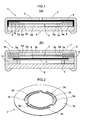
As shown in Figs. 1 and 2, avibration sensor 1 according to the present invention is a vibration sensor for outputting, as vibration signals, variations of capacitance between afixed electrode 2 and adiaphragm electrode 3 opposed to thefixed electrode 2. Thediaphragm electrode 3 hasslits 3a formed in the same plate member to define adiaphragm portion 3b positioned centrally to be vibrated and displaced only by gravity, a fixedportion 3c positioned peripherally, andelastic support portions 3d for connecting thediaphragm portion 3b to the fixedportion 3c. Further, as shown in Fig. 3, an operational amplifier is provided at an output side to act as anamplifier circuit 11. It should be noted that the present invention can be applied to both the front type and back type. - As shown in Fig. 1(a), a front-
type vibration sensor 1 has afixed electrode 2 provided by a bottom portion of acase member 7 having a U-shaped section with anelectret member 4 formed on an inner surface thereof. Successively stacked on the bottom portion of thecase member 7 are a ring-shaped spacer 6, adiaphragm electrode 3 and adiaphragm electrode ring 5. Thecase member 7 is covered with and secured to acircuit board 8, thereby completing assembling of the vibration sensor. Thefixed electrode 2 is connected to thecircuit board 8 through thecase member 7, while thediaphragm electrode 3 is connected to thecircuit board 8 through thediaphragm electrode ring 5. - As shown in Fig. 1(b), a back-
type vibration sensor 1 has adiaphragm electrode ring 5, adiaphragm electrode 3, aspacer 6, afixed electrode 2 with aelectret member 4, aback electrode holder 10 and agate ring 9 successively stacked on a bottom portion of acase member 7. Thecase member 7 is then covered with and secured to acircuit board 8, thereby completing assembling of the vibration sensor. In this construction, thefixed electrode 2 is fixedly supported with peripheral portions thereof pinched by theback electrode holder 10 made of an insulating material. Thefixed electrode 2 is connected to thecircuit board 8 through thegate ring 9. Thediaphragm electrode 3 is connected to thecircuit board 8 through thediaphragm electrode ring 5 andcase member 7. - The thickness of the
diaphragm electrode ring 5 is reduced in both the front-type and back-type in order to improve shock resistance, which contributes to thinning of thevibration sensor 1. It should be noted that theamplifier circuit 11 may be or may not be incorporated in thecircuit board 8. - The
diaphragm electrode 3 is made of SUS304 (stainless steel), for example, and is set to 30µm to 50µm in thickness. Further, thediaphragm electrode 3 has the slits formed in the same plate member to define thediaphragm portion 3b, fixedportion 3c andelastic support portions 3d, and thus can easily be manufactured by press working, etching and so on. - The
diaphragm portion 3b has a circular shape, and its area is determined so as to have a weight for detecting vibrations effectively and obtaining a desired amplitude. Each of theelastic support portions 3d is formed as an arcuate strip member with one end continuous with thediaphragm portion 3b and the other end continuous with the fixedportion 3c. The pluralelastic support portions 3d are arranged at equal intervals circumferentially of thediaphragm portion 3b. In this embodiment, threeelastic support portions 3d of the same shape are arranged at equal intervals circumferentially of thediaphragm portion 3b to assume a three-point support structure, which increases displacement of thediaphragm portion 3b to increase sensor output. The number ofelastic support portions 3d may be selected as desired, though the present embodiment provides threeelastic support portions 3d by taking stability of thevibration sensor 1 and so on into consideration. - The
vibration sensor 1 of this embodiment has undergone tests in which the sensor was dropped as fixed to a box from a height of 1.5meters once in each of the six directions, which has confirmed that no damage is done to thevibration sensor 1, or thediaphragm electrode 3 in particular. Also, a proper thickness of thediaphragm electrode 3 having a diameter of approximately φ4 is 30µm, while a proper thickness of thediaphragm electrode 3 having a diameter of approximately φ6 is 50µm. Although the thickness of thediaphragm electrode 3 having a diameter of approximately φ4 may be set to 50µm, output signals will be diminished. - Fig. 4 shows output voltages under the conditions of resonance frequency (Hz) and low frequency vibrations (2.5Hz and 1.75Hz) with respect to
vibration sensors 1 having the two types ofdiaphragm electrodes 3, one of which is 30µm in thickness and approximately φ4 in diameter, the other is 50µm in thickness and approximately φ6 in diameter. Here, the stage gain of theamplifier circuit 11 is set to 16, while the source voltage is set to 3V. - Next, a second embodiment of the present invention will be described based on Fig. 5.
In this embodiment, thediaphragm portion 3b has a circular shape, and a beam-shapedelastic support portion 3d is formed for connecting a position at an outer periphery of thediaphragm portion 3b to a fixedportion 3c adjacent that position. More particularly, a partlycircular slit 3a is formed to extend inwardly from opposite ends thereof to formstraight slits 3a. In this embodiment, theelastic support portion 3d is formed in one location to have a cantilever beam construction, whereby thediaphragm portion 3b does not make a parallel displacement to prevent thediaphragm electrode 3 from sticking to theelectret member 4. - A third embodiment of the present invention will be described based on Fig. 6.
In this embodiment, as in the second embodiment, thediaphragm portion 3b has a circular shape, and a beam-shapedelastic support portion 3d is formed for connecting a position at an outer periphery of thediaphragm portion 3b to a fixedportion 3c adjacent that position. In this embodiment, a partlycircular slit 3a is formed. As a result, the shape of theslit 3a can be simplified to realize thevibration sensor 1 according to the present invention by providing a simpler construction. - In the first to three embodiments as described above, the plate member is formed of SUS304 (stainless steel). Instead, any material having a high specific gravity and great bending strength may be employed such as tungsten, Ti-Cu alloy, Be-Cu alloy or the like.
- The present invention is useful for a vibration sensor for a pedometer, a micro-vibration galvanometer or a precision device, a vibration sensor for an anti-blur function of a camera, and so on.
-
- [Fig. 1] Sectional views showing an embodiment of a vibration sensor according to the present invention.
- [Fig. 2] Schematic view showing an example of diaphragm electrode of the vibration sensor according to the present invention.
- [Fig. 3] Wiring diagram showing the vibration sensor and a peripheral circuit thereof.
- [Fig. 4] Tables showing examples of resonance frequency and output voltage of the vibration sensor according to the present invention.
- [Fig. 5] Schematic view showing a modified example of diaphragm electrode of the vibration sensor according to the present invention.
- [Fig. 6] Schematic view showing another modified example of diaphragm electrode of the vibration sensor according to the present invention.
-
- 1
- vibration sensor
- 2
- fixed electrode
- 3
- diaphragm electrode
- 4
- electret
- 5
- diaphragm electrode ring
- 6
- spacer
- 7
- case member
- 8
- circuit board
- 9
- gate ring
- 10
- back electrode holder
- 11
- amplifier circuit
Claims (5)
- A vibration sensor for outputting, as vibration signals, variations of capacitance between a fixed electrode and a diaphragm electrode opposed thereto,
wherein the diaphragm electrode has slits formed in the same plate member to define a diaphragm portion positioned centrally to be vibrated and displaced only by gravity, a fixed portion positioned peripherally, and elastic support portions for connecting the diaphragm portion to the fixed portion. - A vibration sensor as defined in Claim 1, wherein the plate member is made of one of stainless steel, tungsten, Ti-Cu alloy and Be-Cu alloy.
- A vibration sensor as defined in Claim 1, wherein the plate member is 30µm to 50µm in thickness.
- A vibration sensor as defined in Claim 1, wherein the diaphragm portion has a circular shape, and each of the elastic support portions is formed as an arcuate strip member with one end continuous with the diaphragm portion and the other end continuous with the fixed portion, a plurality of elastic support portions being arranged at equal intervals circumferentially of the diaphragm portion.
- A vibration sensor as defined in Claim 1, wherein the elastic support portion is formed to have a beam shape for connecting a position of the diaphragm portion at an outer periphery thereof to the fixed portion adjacent said position of the diaphragm portion.
Applications Claiming Priority (2)
| Application Number | Priority Date | Filing Date | Title |
|---|---|---|---|
| JP2003329877A JP2005098726A (en) | 2003-09-22 | 2003-09-22 | Vibration sensor |
| PCT/JP2004/013046 WO2005029013A1 (en) | 2003-09-22 | 2004-09-08 | Vibration sensor |
Publications (1)
| Publication Number | Publication Date |
|---|---|
| EP1666855A1 true EP1666855A1 (en) | 2006-06-07 |
Family
ID=34372979
Family Applications (1)
| Application Number | Title | Priority Date | Filing Date |
|---|---|---|---|
| EP04787729A Withdrawn EP1666855A1 (en) | 2003-09-22 | 2004-09-08 | Vibration sensor |
Country Status (8)
| Country | Link |
|---|---|
| US (1) | US20070107521A1 (en) |
| EP (1) | EP1666855A1 (en) |
| JP (1) | JP2005098726A (en) |
| KR (1) | KR20050029686A (en) |
| CN (1) | CN1853090A (en) |
| CA (1) | CA2529136A1 (en) |
| TW (1) | TWI238245B (en) |
| WO (1) | WO2005029013A1 (en) |
Families Citing this family (8)
| Publication number | Priority date | Publication date | Assignee | Title |
|---|---|---|---|---|
| JP2005098727A (en) * | 2003-09-22 | 2005-04-14 | Hosiden Corp | Vibration sensor |
| CN101294844B (en) * | 2007-04-23 | 2015-07-22 | 成都锐华光电技术有限责任公司 | Bending piezo-electricity type zinc oxide nano stick micromotor(MEMS) vibration transducer |
| US7841234B2 (en) * | 2007-07-30 | 2010-11-30 | Chevron U.S.A. Inc. | System and method for sensing pressure using an inductive element |
| JP5852390B2 (en) * | 2011-01-25 | 2016-02-03 | 日本電波工業株式会社 | Vibration detector |
| WO2012109259A2 (en) | 2011-02-07 | 2012-08-16 | Ion Geophysical Corporation | Method and apparatus for sensing underwater signals |
| CN102538949B (en) * | 2011-12-13 | 2013-08-21 | 江苏大学 | Nano-electromechanical resonant sensor based on graphene sheet layer and manufacturing method thereof |
| CN108362371A (en) * | 2018-04-08 | 2018-08-03 | 东莞泉声电子有限公司 | Vibrate membrane structure and vibration detecting sensor |
| CN115523998A (en) * | 2022-10-26 | 2022-12-27 | 南方电网数字电网研究院有限公司 | Vibration capacitance detection device, system and method and storage medium |
Family Cites Families (19)
| Publication number | Priority date | Publication date | Assignee | Title |
|---|---|---|---|---|
| CH642461A5 (en) * | 1981-07-02 | 1984-04-13 | Centre Electron Horloger | ACCELEROMETER. |
| US4516428A (en) * | 1982-10-28 | 1985-05-14 | Pan Communications, Inc. | Acceleration vibration detector |
| JPS5979700A (en) * | 1982-10-28 | 1984-05-08 | Katsuo Motoi | Detector of vibration |
| JPH037796Y2 (en) * | 1984-12-10 | 1991-02-26 | ||
| US4694687A (en) * | 1986-04-17 | 1987-09-22 | Vericom Corporation | Vehicle performance analyzer |
| US4932258A (en) * | 1988-06-29 | 1990-06-12 | Sundstrand Data Control, Inc. | Stress compensated transducer |
| JP2807919B2 (en) * | 1990-05-30 | 1998-10-08 | 株式会社コパル | Acceleration sensor |
| US5253526A (en) * | 1990-05-30 | 1993-10-19 | Copal Company Limited | Capacitive acceleration sensor with free diaphragm |
| JP3240390B2 (en) * | 1992-03-04 | 2001-12-17 | オムロン株式会社 | Displacement detection sensor |
| US5347867A (en) * | 1993-02-03 | 1994-09-20 | Minnetonka Warehouse Supply, Inc | Accelerometer incorporating a driven shield |
| US5798460A (en) * | 1994-06-20 | 1998-08-25 | Sony Corporation | Vibration sensor employing a flexible diaphragm and an electret film |
| US6026690A (en) * | 1994-06-20 | 2000-02-22 | Sony Corporation | Vibration sensor using the capacitance between a substrate and a flexible diaphragm |
| JPH1026554A (en) * | 1996-07-12 | 1998-01-27 | Omron Corp | Seismic sensor and gas meter |
| JP2000346867A (en) * | 1999-06-02 | 2000-12-15 | Topre Corp | Acceleration sensor |
| EP1613969B1 (en) * | 2003-04-15 | 2009-07-29 | Fraunhofer-Gesellschaft zur Förderung der angewandten Forschung e.V. | Micromechanical component having an adjustable resonance frequency |
| JP4073382B2 (en) * | 2003-09-02 | 2008-04-09 | ホシデン株式会社 | Vibration sensor |
| JP2005098727A (en) * | 2003-09-22 | 2005-04-14 | Hosiden Corp | Vibration sensor |
| JP2006078444A (en) * | 2004-09-13 | 2006-03-23 | Hosiden Corp | Acceleration sensor |
| JP2006084219A (en) * | 2004-09-14 | 2006-03-30 | Hosiden Corp | Acceleration sensor |
-
2003
- 2003-09-22 JP JP2003329877A patent/JP2005098726A/en active Pending
-
2004
- 2004-07-29 TW TW093122750A patent/TWI238245B/en not_active IP Right Cessation
- 2004-09-08 US US10/572,424 patent/US20070107521A1/en not_active Abandoned
- 2004-09-08 WO PCT/JP2004/013046 patent/WO2005029013A1/en not_active Ceased
- 2004-09-08 CA CA002529136A patent/CA2529136A1/en not_active Abandoned
- 2004-09-08 CN CNA200480027160XA patent/CN1853090A/en active Pending
- 2004-09-08 EP EP04787729A patent/EP1666855A1/en not_active Withdrawn
- 2004-09-16 KR KR1020040074106A patent/KR20050029686A/en not_active Ceased
Non-Patent Citations (1)
| Title |
|---|
| See references of WO2005029013A1 * |
Also Published As
| Publication number | Publication date |
|---|---|
| US20070107521A1 (en) | 2007-05-17 |
| CN1853090A (en) | 2006-10-25 |
| TW200512436A (en) | 2005-04-01 |
| WO2005029013A1 (en) | 2005-03-31 |
| KR20050029686A (en) | 2005-03-28 |
| TWI238245B (en) | 2005-08-21 |
| JP2005098726A (en) | 2005-04-14 |
| CA2529136A1 (en) | 2005-03-31 |
Similar Documents
| Publication | Publication Date | Title |
|---|---|---|
| US11265657B2 (en) | Piezoelectric MEMS microphone | |
| EP3668079B1 (en) | Vibratory device and optical detection device | |
| EP0533284A1 (en) | Electroacoustic transducer of the electret type | |
| EP1666854A1 (en) | Vibration sensor | |
| US20210151661A1 (en) | Systems and methods for integrating ultrasonic transducers with hybrid contacts | |
| US20170180864A1 (en) | Center-fixed mems microphone membrane | |
| US20070107521A1 (en) | Vibration sensor | |
| WO2005111555A1 (en) | Vibration sesor | |
| US20160238630A1 (en) | Mems tilt sensor | |
| US6257068B1 (en) | Capacitive pressure sensor having petal electrodes | |
| EP1662238A1 (en) | Vibration sensor | |
| US20020043110A1 (en) | Mechano-electrical sensor | |
| US6556024B2 (en) | Capacitance type load sensor | |
| EP3697105A1 (en) | Speaker unit | |
| JP5113115B2 (en) | Piezoelectric acceleration sensor | |
| EP1715721A1 (en) | Capacity detection type sensor element | |
| KR102890067B1 (en) | Piezoelectric transducers without a conical structure | |
| EP4431893A1 (en) | Load cell | |
| US11212601B1 (en) | Sound transducer and electronic device | |
| JP2006292673A (en) | Acceleration sensor | |
| JP2011242257A (en) | Vibration gyro | |
| WO2002001167A1 (en) | A mechano-electrical sensor for sensing force or vibration | |
| CN103206970B (en) | Microelectromechanical sensor with non-conductive sensing mass, and method of sensing through a microelectromechanical sensor | |
| WO2002103367A1 (en) | Acceleration transducer and method | |
| JPS63120594A (en) | speaker |
Legal Events
| Date | Code | Title | Description |
|---|---|---|---|
| PUAI | Public reference made under article 153(3) epc to a published international application that has entered the european phase |
Free format text: ORIGINAL CODE: 0009012 |
|
| 17P | Request for examination filed |
Effective date: 20051209 |
|
| AK | Designated contracting states |
Kind code of ref document: A1 Designated state(s): DE FI FR GB NL SE |
|
| DAX | Request for extension of the european patent (deleted) | ||
| RBV | Designated contracting states (corrected) |
Designated state(s): DE FI FR GB NL SE |
|
| STAA | Information on the status of an ep patent application or granted ep patent |
Free format text: STATUS: THE APPLICATION HAS BEEN WITHDRAWN |
|
| 18W | Application withdrawn |
Effective date: 20080701 |