EP1666740A2 - Blind rivet - Google Patents
Blind rivet Download PDFInfo
- Publication number
- EP1666740A2 EP1666740A2 EP05111548A EP05111548A EP1666740A2 EP 1666740 A2 EP1666740 A2 EP 1666740A2 EP 05111548 A EP05111548 A EP 05111548A EP 05111548 A EP05111548 A EP 05111548A EP 1666740 A2 EP1666740 A2 EP 1666740A2
- Authority
- EP
- European Patent Office
- Prior art keywords
- rivet
- mandrel
- component
- head
- threaded portion
- Prior art date
- Legal status (The legal status is an assumption and is not a legal conclusion. Google has not performed a legal analysis and makes no representation as to the accuracy of the status listed.)
- Withdrawn
Links
Images


Classifications
-
- F—MECHANICAL ENGINEERING; LIGHTING; HEATING; WEAPONS; BLASTING
- F16—ENGINEERING ELEMENTS AND UNITS; GENERAL MEASURES FOR PRODUCING AND MAINTAINING EFFECTIVE FUNCTIONING OF MACHINES OR INSTALLATIONS; THERMAL INSULATION IN GENERAL
- F16B—DEVICES FOR FASTENING OR SECURING CONSTRUCTIONAL ELEMENTS OR MACHINE PARTS TOGETHER, e.g. NAILS, BOLTS, CIRCLIPS, CLAMPS, CLIPS OR WEDGES; JOINTS OR JOINTING
- F16B19/00—Bolts without screw-thread; Pins, including deformable elements; Rivets
- F16B19/04—Rivets; Spigots or the like fastened by riveting
- F16B19/05—Bolts fastening by swaged-on collars
-
- B—PERFORMING OPERATIONS; TRANSPORTING
- B21—MECHANICAL METAL-WORKING WITHOUT ESSENTIALLY REMOVING MATERIAL; PUNCHING METAL
- B21J—FORGING; HAMMERING; PRESSING METAL; RIVETING; FORGE FURNACES
- B21J15/00—Riveting
- B21J15/02—Riveting procedures
- B21J15/022—Setting rivets by means of swaged-on locking collars, e.g. lockbolts
-
- F—MECHANICAL ENGINEERING; LIGHTING; HEATING; WEAPONS; BLASTING
- F16—ENGINEERING ELEMENTS AND UNITS; GENERAL MEASURES FOR PRODUCING AND MAINTAINING EFFECTIVE FUNCTIONING OF MACHINES OR INSTALLATIONS; THERMAL INSULATION IN GENERAL
- F16B—DEVICES FOR FASTENING OR SECURING CONSTRUCTIONAL ELEMENTS OR MACHINE PARTS TOGETHER, e.g. NAILS, BOLTS, CIRCLIPS, CLAMPS, CLIPS OR WEDGES; JOINTS OR JOINTING
- F16B23/00—Specially shaped nuts or heads of bolts or screws for rotations by a tool
- F16B23/0069—Specially shaped nuts or heads of bolts or screws for rotations by a tool with holes to be engaged with corresponding pins on the tool or protruding pins to be engaged with corresponding holes on the tool
-
- F—MECHANICAL ENGINEERING; LIGHTING; HEATING; WEAPONS; BLASTING
- F16—ENGINEERING ELEMENTS AND UNITS; GENERAL MEASURES FOR PRODUCING AND MAINTAINING EFFECTIVE FUNCTIONING OF MACHINES OR INSTALLATIONS; THERMAL INSULATION IN GENERAL
- F16B—DEVICES FOR FASTENING OR SECURING CONSTRUCTIONAL ELEMENTS OR MACHINE PARTS TOGETHER, e.g. NAILS, BOLTS, CIRCLIPS, CLAMPS, CLIPS OR WEDGES; JOINTS OR JOINTING
- F16B35/00—Screw-bolts; Stay-bolts; Screw-threaded studs; Screws; Set screws
- F16B35/04—Screw-bolts; Stay-bolts; Screw-threaded studs; Screws; Set screws with specially-shaped head or shaft in order to fix the bolt on or in an object
- F16B35/041—Specially-shaped shafts
- F16B35/048—Specially-shaped necks
Definitions
- This invention relates to blind rivets and in particular to blind rivets for forming an electrical connection to a metal component.
- blind rivets make a considerable contribution to reducing the cost of a component or assembly through increased assembly speed and of the low cost of the rivet itself. For instance, without the benefit of blind rivets assemblies would have to be bolted together and there would be an attendant increase in assembly time would result. Also where the weight of an assembly is to be a minimum then using fasteners such as nuts and bolts would increase weight and design complexity compared with the use of blind rivet technology. Furthermore it is known that the simplicity and low cost blind rivet techniques afford are more cost effective compared with other means of assembly such as welding or self-piercing riveting require the use of specialist equipment that is expensive and inappropriate where very thin materials are being used.
- An object of the present invention is to provide a rivet for attachment to a component that has splines that improve electrical contact between the rivet and one or more metal components and is easy to remove.
- the head of the mandrel is a countersunk head for location in a complementary shaped recess in the predefined hole in component and the head has a recess for receiving a complementary shaped tool.
- the head may comprise a multi-facetted body for location in a complementary shaped recess in the predefined hole in the component.
- the head may be of hexagonal shape.
- the head may be of a domed shape and have a recess in the convex surface of the dome for receiving a complementary shaped tool.
- the stem has a grooved outer surface.
- the swaging of the body to the external thread is achieved by pushing a nose piece that has a shaped internal profile, (preferably hexagon shaped), over the body so that the nose piece profile is formed on the outer surface of the body during the swaging step.
- a nose piece that has a shaped internal profile, (preferably hexagon shaped)
- a first and a second component may be provided each having an aligned predefined hole, the hole in the first component being of larger diameter than that in the second component, and the step of setting the rivet causes the head of the mandrel to deform the second component into the hole of the first component.
- the rivet may be subsequently removed from the one or more components by unscrewing the swaged body from the threaded portion of the mandrel using a suitable tool.
- the rivet 20 comprises a mandrel 1 and a hollow body 2.
- the mandrel 1 is best seen in Figures 3 to 6 and has a head 3 that is of a countersunk shape and has a recess 4 for receiving a tool (not shown) such as a screwdriver, Allen key, or a similar tool.
- the recess is of a shape complementary to that of the tool.
- the recess 4 could be a slot to receive a flat bladed screwdriver, or a cross - head slot (such as a Pozidrive (Trade Mark) or a Phillips (Trade Mark) screwdriver.
- the head 3 of the mandrel is shown as being countersunk form (i.e. it has a conical profile) it is to be understood that it could be of any desired shape, such as for example, a dome shape, a cylindrical shape, an elliptical shape or a multi facetted body (e.g. hexagonal, polygonal, or the like).
- the mandrel 1 further comprises a splined portion 5 immediately adjacent the head 3, a threaded portion 7 immediately adjacent the splined portion 5 and a stem 8 having external grooves 9 to provide a gripping surface for a setting tool to grip as will be explained hereinafter.
- the grooves could be axially spaced grooves as shown or a helical screw thread groove (not shown).
- the stem 8 is connected to the threaded portion 7 by a frangible region 10 that is designed to break at a predetermined load during setting of the rivet 20.
- the body 2 is a hollow body made of a ductile metal and has a shank 12 and a flange 13.
- the bore 14 of the body 2 is dimensioned so that it can be slid over the outside diameter of the threaded portion 7 of the mandrel.
- the body 2 has a ductility that allows the shank 12 to be swaged onto the threaded portion 7 of the mandrel 1, as will be explained hereinafter.
- the mandrel 1 is inserted into a predefined hole 18 in one component 16 to bring the splined portion 5 of the mandrel into contact with the hole 18 of the component 16.
- the component 16 has a slightly smaller diameter hole 18 that overlaps the hole 19 in component 15.
- the hole 18 may be punched or drilled through and may have a countersunk recess that is of complimentary shape to that of the head 3 of the mandrel 1 to accommodate the head 3.
- Operation of the tool 21 to set the rivet 20 causes the nose 22 of the tool to push the flange 13 against the component 15.
- the jaws 22 pull the head 3 of the mandrel 1 towards the component 16 to force the splined portion 5 into the hole 18 and bring the head 3 into intimate contact with the component 16. This action causes the head 3 to deform the component 16 into the hole 19 of component 15.
- the internal bore 24 of the nose piece 23 of the setting tool is for convenience shown in Figure 11 and takes the form of a hexagon or any other polygonal shape.
- the inner bore 14 of the body 2 is deformed into the threaded portion 7 of the stem 8 so that the body is locked in-place. It follows that the polygonal or hexagon form of the nose piece is impressed in a similar polygonal or hexagon form 25 on the outer surface of the body as shown in Figure 7a.
- the mandrel 1 breaks at the frangible zone 10 (as shown in Figure 10) and the separate portion of the mandrel is removed leaving the rivet 20 firmly attached to the components 15, 16 (as shown in Figure 11).
- a tool such as a screwdriver or Allen key (not shown) is inserted into the recess 4 in the head 3 and the body is unscrewed from the mandrel 1 using a suitable spanner that can easily apply a rotational torque to the body 2, and thus body and mandrel can be discarded or even reused using the same tools.
Landscapes
- Engineering & Computer Science (AREA)
- General Engineering & Computer Science (AREA)
- Mechanical Engineering (AREA)
- Insertion Pins And Rivets (AREA)
Abstract
Description
- This invention relates to blind rivets and in particular to blind rivets for forming an electrical connection to a metal component.
- It has long been recognised that blind rivets make a considerable contribution to reducing the cost of a component or assembly through increased assembly speed and of the low cost of the rivet itself. For instance, without the benefit of blind rivets assemblies would have to be bolted together and there would be an attendant increase in assembly time would result. Also where the weight of an assembly is to be a minimum then using fasteners such as nuts and bolts would increase weight and design complexity compared with the use of blind rivet technology. Furthermore it is known that the simplicity and low cost blind rivet techniques afford are more cost effective compared with other means of assembly such as welding or self-piercing riveting require the use of specialist equipment that is expensive and inappropriate where very thin materials are being used.
- However, recent European legislation evolving from environmental concerns is beginning to have an impact on everyday assemblies where permanent, high speed fixing afforded by blind rivets is being questioned. British Building Regulations 2000 (SI200/2531), CE Marking, COSH Regulations and Safety at Work Acts are some of the formal requirements that apply pressure on the designers, especially of florescent lighting devices, to incorporate simple means of dismantling without compromising the cost of the assembly. Domestic and industrial lighting industries perceive the need to recycle high percentages of components and materials as well as making more energy efficient appliances.
- The continued use of blind rivets to secure components that need to be removed and recycled due to the high material cost or potential damage on the environment will ultimately create extra cost due to increased design complexity as an alternative to a permanent fixing. It could be envisaged that costly three piece nut, screw and shake-proof washer would be the only likely alternative, but with a higher in-place cost penalty.
- There is therefore, a need to provide a good electrical connection to metal components that is both relatively cheap and reliable and can easily be dismantled.
- An object of the present invention is to provide a rivet for attachment to a component that has splines that improve electrical contact between the rivet and one or more metal components and is easy to remove.
- According to the present invention there is provided a rivet for attachment to one or more components by insertion through a predefmed hole in the one or more components, the rivet comprising:
- (a) a mandrel having a head, a splined portion adjacent the head for engaging the component, an externally threaded portion adjacent the splined portion, and a stem portion connected to the threaded portion by a frangible zone, and
- (b) a hollow body of ductile material having a flange for contacting the component on a side opposite to that contacted by the head of the mandrel, a bore that is dimensioned so as to be capable, in use, of sliding over the outside of the threaded portion of the mandrel to bring the flange into contact with the component and capable of being swaged onto the external thread of the threaded portion thereby to secure the body to the threaded portion during setting of the rivet.
- Preferably the head of the mandrel is a countersunk head for location in a complementary shaped recess in the predefined hole in component and the head has a recess for receiving a complementary shaped tool.
- The head may comprise a multi-facetted body for location in a complementary shaped recess in the predefined hole in the component. In this case the head may be of hexagonal shape. The head may be of a domed shape and have a recess in the convex surface of the dome for receiving a complementary shaped tool.
- Preferably the stem has a grooved outer surface.
- According to a further aspect of the present invention there is provided a method of securing a rivet to a component comprising the steps of
- (c) providing a rivet constructed in accordance with any one of the attached
claims 1 to 6; - (d) providing one or more components with a predefined hole in which the rivet is to be inserted,
- (e) inserting the rivet into the predefined hole of the component so as to bring the splined portion of the mandrel into contact with the one or more components on one side of the one or more components;
- (f) sliding the body over the threaded portion of the mandrel so as to bring the flange into contact with the component on a side of the component remote from that contacted by the splined portion,
- (g) placing a tool onto the stem of the mandrel so as to grip the mandrel, and
- (h) setting the rivet by operating the tool to pull the head of the mandrel towards the component until the frangible zone breaks whilst pushing the flange against the one or more components on a side of the one or more components remote from the head of the rivet and thereby force the splined portion into the predefined hole and cause the rivet to set by swaging the body onto the threaded portion of the mandrel.
- Preferably the swaging of the body to the external thread is achieved by pushing a nose piece that has a shaped internal profile, (preferably hexagon shaped), over the body so that the nose piece profile is formed on the outer surface of the body during the swaging step.
- A first and a second component may be provided each having an aligned predefined hole, the hole in the first component being of larger diameter than that in the second component, and the step of setting the rivet causes the head of the mandrel to deform the second component into the hole of the first component.
- The rivet may be subsequently removed from the one or more components by unscrewing the swaged body from the threaded portion of the mandrel using a suitable tool.
- The present invention will now be described by way of example with reference to the accompanying drawings in which;
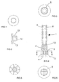
- Figure 1 is an end view of a body of a rivet constructed in accordance with the present invention;
- Figure 2 is a side view of the body that is used in conjunction with the mandrel of Figure 4;
- Figure 3 is an end view of a mandrel of a rivet constructed in accordance with the present invention;
- Figure 4 is a side view of the mandrel shown in Figure 3;
- Figure 5 is an end view of the mandrel of Figures 3, and 4 looking at the head of the mandrel;
- Figure 6 is a cross sectional view taken along line 6-6 of Figure 4;
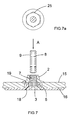
- Figure 7 is a cross sectional view of a rivet constructed in accordance with the present invention and shows the rivet after it has been set and attached to a component and a hexagon shape generated on the swaged body; and,
- Figures 8 to 11 show schematically the method of setting the rivet of Figures 1 to 7.
- Referring to Figures 1 to 6 the
rivet 20 comprises amandrel 1 and ahollow body 2. Themandrel 1 is best seen in Figures 3 to 6 and has ahead 3 that is of a countersunk shape and has arecess 4 for receiving a tool (not shown) such as a screwdriver, Allen key, or a similar tool. The recess is of a shape complementary to that of the tool. For example, therecess 4 could be a slot to receive a flat bladed screwdriver, or a cross - head slot (such as a Pozidrive (Trade Mark) or a Phillips (Trade Mark) screwdriver. - Although the
head 3 of the mandrel is shown as being countersunk form (i.e. it has a conical profile) it is to be understood that it could be of any desired shape, such as for example, a dome shape, a cylindrical shape, an elliptical shape or a multi facetted body (e.g. hexagonal, polygonal, or the like). - The
mandrel 1 further comprises asplined portion 5 immediately adjacent thehead 3, a threadedportion 7 immediately adjacent thesplined portion 5 and astem 8 havingexternal grooves 9 to provide a gripping surface for a setting tool to grip as will be explained hereinafter. The grooves could be axially spaced grooves as shown or a helical screw thread groove (not shown). - The
stem 8 is connected to the threadedportion 7 by afrangible region 10 that is designed to break at a predetermined load during setting of therivet 20. - Referring to Figures 1 and 2 the
body 2 is a hollow body made of a ductile metal and has ashank 12 and aflange 13. Thebore 14 of thebody 2 is dimensioned so that it can be slid over the outside diameter of the threadedportion 7 of the mandrel. Thebody 2 has a ductility that allows theshank 12 to be swaged onto the threadedportion 7 of themandrel 1, as will be explained hereinafter. - Referring to Figure 7, the
mandrel 1 is inserted into apredefined hole 18 in onecomponent 16 to bring thesplined portion 5 of the mandrel into contact with thehole 18 of thecomponent 16. In Figure 7 there are twocomponents components 15 has alarger diameter hole 19 than theother component 16. Thecomponent 16 has a slightlysmaller diameter hole 18 that overlaps thehole 19 incomponent 15. - In the case of
thick component 16 thehole 18 may be punched or drilled through and may have a countersunk recess that is of complimentary shape to that of thehead 3 of themandrel 1 to accommodate thehead 3. - Referring to Figure 8 once the mandrel is inserted into the
predefined hole 18 thebody 2 is slid over the outside of the threadedportion 7 to bring theflange 13 of thebody 2 into contact with a side of thecomponent 15 that is remote from that where thesplined portion 5 contacts thecomponent 16. Asetting tool 21 is then offered up to thestem 8 so that thejaws 22 of thesetting tool 21 grip thestem 8 of themandrel 1 and thenose 23 of thetool 21 engages the flange 11 of the body. - Operation of the
tool 21 to set therivet 20 causes thenose 22 of the tool to push theflange 13 against thecomponent 15. At the same time thejaws 22 pull thehead 3 of themandrel 1 towards thecomponent 16 to force thesplined portion 5 into thehole 18 and bring thehead 3 into intimate contact with thecomponent 16. This action causes thehead 3 to deform thecomponent 16 into thehole 19 ofcomponent 15. - Continued operation of the
tool 21 as shown in Figure 9 causes thenose 23 to swage theshank 12 of thebody 2 onto the threadedportion 5. Theinternal bore 24 of thenose piece 23 of the setting tool is for convenience shown in Figure 11 and takes the form of a hexagon or any other polygonal shape. As theshank 12 of thebody 2 is swaged, theinner bore 14 of thebody 2 is deformed into the threadedportion 7 of thestem 8 so that the body is locked in-place. It follows that the polygonal or hexagon form of the nose piece is impressed in a similar polygonal orhexagon form 25 on the outer surface of the body as shown in Figure 7a. - At a predetermined load, the
mandrel 1 breaks at the frangible zone 10 (as shown in Figure 10) and the separate portion of the mandrel is removed leaving therivet 20 firmly attached to thecomponents 15, 16 (as shown in Figure 11). - If it is required later to remove the
rivet 20 from thecomponents recess 4 in thehead 3 and the body is unscrewed from themandrel 1 using a suitable spanner that can easily apply a rotational torque to thebody 2, and thus body and mandrel can be discarded or even reused using the same tools.
Claims (12)
- A rivet for attachment to one or more components (15, 16) by insertion through a predefmed hole (18, 19) in the one or more components, the rivet comprising:(a) a mandrel (1) having a head (3), a splined portion (5) adjacent the head for engaging the component (16), an externally threaded portion (7) adjacent the splined portion, and a stem portion connected to the threaded portion (7) by a frangible zone (10), and(b) a hollow body (2) of ductile material having a flange (13) for contacting the component (15) on a side opposite to that contacted by the head (3) of the mandrel (1), a bore that is dimensioned so as to be capable, in use, of sliding over the outside of the threaded portion (7) of the mandrel (1) to bring the flange (13) into contact with the component (15) and capable of being swaged onto the external thread of the threaded portion (7) thereby to secure the body (2) to the threaded portion (7) during setting of the rivet.
- A rivet according to Claim 1 wherein the head (3) of the mandrel (1) is a countersunk head for location in a complementary shaped recess in the predefined hole (18) in component (16) and the head has a recess (4) for receiving a complementary shaped tool.
- A rivet according to Claim 1 wherein the head (3) comprises a multi-facetted body for location in a complementary shaped recess in the predefined hole in the component.
- A rivet according to Claim 3 wherein the head (3) is of hexagonal shape.
- A rivet according to Claim 1 wherein the head (3) is of a domed shape and the head has a recess in the convex surface of the dome for receiving a complementary shaped tool.
- A rivet according to any one of the preceding Claims wherein the stem (8) has a grooved outer surface.
- A method of securing a rivet to a component comprising the steps of(a) providing a rivet constructed in accordance with any one of the preceding claims;(b) providing one or more components (15, 16) with a predefined hole (18, 19) in which the rivet is to be inserted,(c) inserting the rivet into the predefined hole (18) of the component (15) so as to bring the splined portion (5) of the mandrel (1) into contact with the one or more components on one side of the one or more components;(d) sliding the body (2) over the threaded portion (7) of the mandrel (1) so as to bring the flange (13) into contact with the component (16) on a side of the component remote from that contacted by the splined portion (5),(e) placing a tool onto the stem (8) of the mandrel (1)so as to grip the mandrel (1), and(f) setting the rivet by operating the tool to pull the head (3) of the mandrel (1) towards the component (16) until the frangible zone (10) breaks whilst pushing the flange (13) against the one or more components (15) on a side of the one or more components remote from the head (3) of the rivet and thereby force the splined portion (5) into the predefined hole (18) and cause the rivet to set by swaging the body (2) onto the threaded portion (7) of the mandrel (1).
- A method according to Claim 7 wherein the step of swaging the body (2) onto the threaded portion (7) is carried out with a tubular tool that has a predetermined cross-sectional shaped bore that impresses the shape of the bore on the outer surface of the body during the swaging step.
- A method according to Claim 7 wherein the cross sectional shape of the bore and the impressed shape on the outer surface of the body (2) is polygonal shaped so that complimentary tools can be applied to remove the rivet.
- A method according to claim 9 wherein the polygonal shape is a hexagon.
- A method according to claim 7 wherein there is a first and a second component (15, 16) each having an aligned predefined hole (18, 19), the hole (19) in the first component (15) being of larger diameter than that in the second component (16), and the step of setting the rivet causes the head (3) of the mandrel (1) to deform the second component (16) into the hole (19) of the first component (15).
- A method according to any one of claims 7 or 8 wherein the rivet is subsequently removed from the one or more components by unscrewing the threaded portion of the body (2) from the threaded portion (7) of the mandrel (1).
Applications Claiming Priority (1)
| Application Number | Priority Date | Filing Date | Title |
|---|---|---|---|
| GB0426578A GB2420835B (en) | 2004-12-03 | 2004-12-03 | Blind rivet |
Publications (2)
| Publication Number | Publication Date |
|---|---|
| EP1666740A2 true EP1666740A2 (en) | 2006-06-07 |
| EP1666740A3 EP1666740A3 (en) | 2006-07-26 |
Family
ID=34044021
Family Applications (1)
| Application Number | Title | Priority Date | Filing Date |
|---|---|---|---|
| EP05111548A Withdrawn EP1666740A3 (en) | 2004-12-03 | 2005-12-01 | Blind rivet |
Country Status (2)
| Country | Link |
|---|---|
| EP (1) | EP1666740A3 (en) |
| GB (1) | GB2420835B (en) |
Cited By (2)
| Publication number | Priority date | Publication date | Assignee | Title |
|---|---|---|---|---|
| FR3013617A1 (en) * | 2013-11-22 | 2015-05-29 | Airbus Operations Sas | METHOD OF ASSEMBLY DISASSEMBLY BETWEEN TWO PIECES BY ADAPTABLE DEFORMATION OF A CRIMPING RING. |
| WO2026084726A1 (en) * | 2024-10-18 | 2026-04-23 | Howmet Aerospace Inc. | Lockbolt fasteners and methods for fastening |
Families Citing this family (1)
| Publication number | Priority date | Publication date | Assignee | Title |
|---|---|---|---|---|
| ITTO20070254A1 (en) | 2007-04-12 | 2008-10-13 | Bruno Bisiach | HEAD FOR REPLACEMENT MACHINE AND ITS CONTROL METHOD. |
Family Cites Families (9)
| Publication number | Priority date | Publication date | Assignee | Title |
|---|---|---|---|---|
| BE542528A (en) * | 1945-12-29 | |||
| US2972274A (en) * | 1955-04-18 | 1961-02-21 | Bombard Emerson H La | Self broaching fastener |
| AU646394B2 (en) * | 1989-05-31 | 1994-02-24 | Huck International, Inc. | Fastener system including a swage fastener and tool for installing same |
| US4983085A (en) * | 1989-09-26 | 1991-01-08 | Northrop Corporation | Threaded lockable fastener with swaged collar |
| EP0663535A1 (en) * | 1992-07-03 | 1995-07-19 | Emhart Inc. | Component mounting assembly and method |
| EP0834974B1 (en) * | 1996-10-04 | 2002-12-11 | Elek Gmbh | Frame for a switchgear cabinet |
| DE20116901U1 (en) * | 2001-10-15 | 2002-12-19 | Schmitz Cargobull AG, 48341 Altenberge | Joint connection for metal elements and fitting screws for such a joint connection |
| JP2003322124A (en) * | 2002-04-26 | 2003-11-14 | Nippon Pop Rivets & Fasteners Ltd | Blind rivet and fastening method |
| US6665922B2 (en) * | 2002-05-13 | 2003-12-23 | Hi-Shear Corporation | Pull stem hi-lite pin with pull groove for swaging collars |
-
2004
- 2004-12-03 GB GB0426578A patent/GB2420835B/en not_active Expired - Fee Related
-
2005
- 2005-12-01 EP EP05111548A patent/EP1666740A3/en not_active Withdrawn
Cited By (2)
| Publication number | Priority date | Publication date | Assignee | Title |
|---|---|---|---|---|
| FR3013617A1 (en) * | 2013-11-22 | 2015-05-29 | Airbus Operations Sas | METHOD OF ASSEMBLY DISASSEMBLY BETWEEN TWO PIECES BY ADAPTABLE DEFORMATION OF A CRIMPING RING. |
| WO2026084726A1 (en) * | 2024-10-18 | 2026-04-23 | Howmet Aerospace Inc. | Lockbolt fasteners and methods for fastening |
Also Published As
| Publication number | Publication date |
|---|---|
| GB2420835B (en) | 2008-01-16 |
| EP1666740A3 (en) | 2006-07-26 |
| GB2420835A (en) | 2006-06-07 |
| GB0426578D0 (en) | 2005-01-05 |
Similar Documents
| Publication | Publication Date | Title |
|---|---|---|
| US8777533B2 (en) | Blind fastener | |
| US8511952B2 (en) | Dual-action disposable clamp | |
| US8517649B2 (en) | Dual-action disposable clamp | |
| US8979453B2 (en) | Blind fastener | |
| EP0655559B1 (en) | Dual-function fastener and method of use | |
| US9464654B2 (en) | Fastener and method of installing same | |
| CA2516052C (en) | Blind fastener and method of removing it from a workpiece | |
| US3276308A (en) | Blind fasteners | |
| EP1529170B1 (en) | Blind fastener and drive nut assembly and method of installation thereof | |
| US20120263556A1 (en) | Fastener and method of installing same | |
| US8961086B2 (en) | Fastener and method of installing same | |
| EP1841552B1 (en) | Method for removing blind fasteners | |
| EP4435277B1 (en) | Fastener, fastening assembly and method of installing a fastener | |
| EP3921552B1 (en) | Blind fastener and method of installation thereof | |
| GB2420835A (en) | Swaged rivet | |
| KR101449188B1 (en) | Fastening structure of blind bolt with a stabel head | |
| US11739780B2 (en) | Functional element | |
| EP4535571A1 (en) | Grounding contact and method for assembling a ground cable and a component | |
| GB2401662A (en) | Removable blind rivet | |
| US2991681A (en) | Tubular rivet having frangible tool gripping portion | |
| HK1138345B (en) | Zero-clearance bolted joint |
Legal Events
| Date | Code | Title | Description |
|---|---|---|---|
| PUAI | Public reference made under article 153(3) epc to a published international application that has entered the european phase |
Free format text: ORIGINAL CODE: 0009012 |
|
| AK | Designated contracting states |
Kind code of ref document: A2 Designated state(s): AT BE BG CH CY CZ DE DK EE ES FI FR GB GR HU IE IS IT LI LT LU LV MC NL PL PT RO SE SI SK TR |
|
| AX | Request for extension of the european patent |
Extension state: AL BA HR MK YU |
|
| PUAL | Search report despatched |
Free format text: ORIGINAL CODE: 0009013 |
|
| AK | Designated contracting states |
Kind code of ref document: A3 Designated state(s): AT BE BG CH CY CZ DE DK EE ES FI FR GB GR HU IE IS IT LI LT LU LV MC NL PL PT RO SE SI SK TR |
|
| AX | Request for extension of the european patent |
Extension state: AL BA HR MK YU |
|
| RIC1 | Information provided on ipc code assigned before grant |
Ipc: B21J 15/02 20060101ALI20060622BHEP Ipc: F16B 35/04 20060101ALI20060622BHEP Ipc: F16B 23/00 20060101ALI20060622BHEP Ipc: F16B 19/05 20060101AFI20060622BHEP |
|
| 17P | Request for examination filed |
Effective date: 20070123 |
|
| 17Q | First examination report despatched |
Effective date: 20070306 |
|
| AKX | Designation fees paid |
Designated state(s): AT BE BG CH CY CZ DE DK EE ES FI FR GB GR HU IE IS IT LI LT LU LV MC NL PL PT RO SE SI SK TR |
|
| STAA | Information on the status of an ep patent application or granted ep patent |
Free format text: STATUS: THE APPLICATION IS DEEMED TO BE WITHDRAWN |
|
| 18D | Application deemed to be withdrawn |
Effective date: 20091013 |