EP1666657A1 - Low-noise household clothes drying machine - Google Patents
Low-noise household clothes drying machine Download PDFInfo
- Publication number
- EP1666657A1 EP1666657A1 EP04106204A EP04106204A EP1666657A1 EP 1666657 A1 EP1666657 A1 EP 1666657A1 EP 04106204 A EP04106204 A EP 04106204A EP 04106204 A EP04106204 A EP 04106204A EP 1666657 A1 EP1666657 A1 EP 1666657A1
- Authority
- EP
- European Patent Office
- Prior art keywords
- drum
- air
- conduit
- machine according
- drying
- Prior art date
- Legal status (The legal status is an assumption and is not a legal conclusion. Google has not performed a legal analysis and makes no representation as to the accuracy of the status listed.)
- Granted
Links
Images



Classifications
-
- D—TEXTILES; PAPER
- D06—TREATMENT OF TEXTILES OR THE LIKE; LAUNDERING; FLEXIBLE MATERIALS NOT OTHERWISE PROVIDED FOR
- D06F—LAUNDERING, DRYING, IRONING, PRESSING OR FOLDING TEXTILE ARTICLES
- D06F58/00—Domestic laundry dryers
- D06F58/20—General details of domestic laundry dryers
-
- D—TEXTILES; PAPER
- D06—TREATMENT OF TEXTILES OR THE LIKE; LAUNDERING; FLEXIBLE MATERIALS NOT OTHERWISE PROVIDED FOR
- D06F—LAUNDERING, DRYING, IRONING, PRESSING OR FOLDING TEXTILE ARTICLES
- D06F58/00—Domestic laundry dryers
- D06F58/02—Domestic laundry dryers having dryer drums rotating about a horizontal axis
- D06F58/04—Details
-
- D—TEXTILES; PAPER
- D06—TREATMENT OF TEXTILES OR THE LIKE; LAUNDERING; FLEXIBLE MATERIALS NOT OTHERWISE PROVIDED FOR
- D06F—LAUNDERING, DRYING, IRONING, PRESSING OR FOLDING TEXTILE ARTICLES
- D06F58/00—Domestic laundry dryers
- D06F58/32—Control of operations performed in domestic laundry dryers
- D06F58/34—Control of operations performed in domestic laundry dryers characterised by the purpose or target of the control
- D06F58/52—Preventing or reducing noise
Definitions
- the present invention refers to an improved kind of clothes drying machine, preferably of the type for use in households, which is provided with improved means for circulating the drying air that are improved to ensure high energy efficiency and low-noise operation.
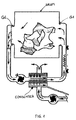
- the present invention therefore applies also to the so-called exhaust-type clothes drying machines, in which the air is taken from the outside ambient, duly heated up, blown into the rotating drum, removed from the same rotating drum and, eventually, exhausted again into the outside ambient, as opposed to what occurs in condenser-type clothes drying machines, in which the air is on the contrary caused to circulate in a closed-loop circuit that includes a suitable condenser arrangement, so as this is illustrated symbolically in Figure 1.
- Both condenser-type and exhaust-type clothes drying machines share - further to the rotating drum - a common operating feature, i.e. the circumstance that in both cases there are provided an air delivery or inflow conduit and an outflow conduit, along with related openings arranged in the walls of the drum, through and in which the drying air is caused to circulate with the aid of means largely known as such in the art.
- a drum 1 adapted to hold the clothes to be dried, to which there is associated a delivery conduit 2 letting the drying air into the drum through an appropriate inflow opening 3, an air outlet or exhaust conduit 4 removing the drying air from the interior of the drum through a corresponding outflow opening 5, wherein said conduits 2 and 4 are joined to each other via a condenser 6, which is adapted to cause the moisture contained in the drying air flowing therethough to condense, said condenser being furthermore flown through by a flow of "cold" air, i.e. air taken in from the outside ambient and sent to said condenser 6 via a corresponding cooling conduit (not shown).
- "cold" air i.e. air taken in from the outside ambient and sent to said condenser 6 via a corresponding cooling conduit (not shown).
- said drum is entirely muffled and enclosed in a substantially closed container 8, with the sole exceptions that shall be pointed out further on in this description, being preferably in the shape of a cylinder so as to as far as possible closely follow the contour of the drum contained therein, while avoiding to occupy any excessive additional space inside the outer casing of the clothes drying machine, so as this is better illustrated in Figure 3.
- This cylindrical container 8 is provided with related parallel bases 9 and 10; in each one of these bases there is provided a related opening 11, 12, through which the corresponding air delivery conduit 2 and outlet conduit 4 are allowed to pass.
- the connection at which said air delivery conduit 2 flows into the corresponding inflow opening 11 is of the sealed, i.e. air-tight type; the same applies as far as the connection at which said air outlet conduit 4 flows into the corresponding outflow opening 12 is concerned.
- said cylindrical container 8 is suspended inside the outer casing of the clothes drying machine with the aid of means that are largely known as such in the art (not shown in the Figures).
- said container 8 does not only contain the drum 1 thereinside, but also the portions 2A and 4A of the air delivery conduit 2 and the air outlet conduit 4, which penetrate into and extend beyond the respective openings 11 and 12.
- said container 8 proves effective in enabling the desired result to be fully attained, since it encloses the entire drum thereinside, so that the noise generated in said drum, and leaking out towards the outside ambient, is deadened in a most effective, radical manner.
- one of these improvements consists in designing the delivery conduit 2 so that a section thereof features a portion that it shares with the base 9, which it extends through, wherein this common portion may be an outwardly facing portion 2B of the conduit 2.
- a section of the outlet conduit 4 features a portion that it shares with the base 10, which it extends through., wherein this common portion may be an outwardly facing portion 4B of the conduit 4.
- FIG. 3 and 4 are just symbolical views and are used to represent in a simple and readily appreciable manner what is actually the core of the present invention.
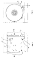
- Figure 5 is a view illustrating an embodiment of the present invention, which is closer to a real machine and provides further construction-related advantages.
- said container 8 is constituted by a substantially cylindrical wrapper, i.e. side wall which, further to containing the drum 1 and other members and parts associated therewith, as described in greater detail below, is not provided with any base, i.e. front and rear walls of its own, but shuts both frontally and at the rear by abutting against respective portions 16 and 17 of the front wall and the rear wall, respectively, of the outer casing of the machine.
- the axis X of the cylindrical contour of said container 8 is most suitably caused to coincide with the axis of the drum 1, which is conventionally made in the shape of a cylinder, and which is driven to rotate about an axis of rotation that in turn coincides with said axis X.
- the drive motor 7 used to rotatably drive the clothes holding drum is also included, jointly with the driving belt 18 used to transmit motion from the motor pulley to the exterior of the drum 1 in a manner largely known as such in the art, inside the container 8.
- said motor 7 is mounted on the inner surface of the container 8, to which it is secured with the aid of generally known fastening means. Furthermore, for it to be adapted to accommodate said motor 7, said container 8 is shaped so as to feature a suitably shaped niche-like accommodation 19, so that the container 8 practically behaves as a "skin" that encloses solely the drum and the motor, further to obviously a part of the delivery and exhaust conduits. It therefore does not add any particular complication to the construction and the operation of the machine.
- a further improvement consists in providing the wall of the drum with a number of perforations 20, so that any air that may possibly leak into the gap or hollow space 21 between the drum 1 and said container 8, is allowed, by passing through said perforations 20, to flow back again into the drum and contribute to the drying process.
- a further advantage of such solution lies in the fact that the air flowing back into the drum through said perforations impinges upon the clothes, i.e. the drying load from outside, thereby favouring a more rapid and uniform drying effect, since the main flow of drying air passes through the drum in an axial direction and, therefore, impinges in a preferential manner upon those portions of clothes or drying items that lie in the central zone of the drum, while it does so in a more limited manner as far as the drying items are concerned, which lie in zones that are closer to the wall of the same drum.
Landscapes
- Engineering & Computer Science (AREA)
- Textile Engineering (AREA)
- Detail Structures Of Washing Machines And Dryers (AREA)
Abstract
Description
- The present invention refers to an improved kind of clothes drying machine, preferably of the type for use in households, which is provided with improved means for circulating the drying air that are improved to ensure high energy efficiency and low-noise operation.
- The machines, which the present invention refers to, are generally known in the art. They have on the other hand been described, along with a detailed discussion of a technical nature on the advantages and the drawbacks of a number of different variations in the design and general embodiment thereof, in the Italian patent application no. PN2003U000015 filed by this same Applicant with the title "Household Clothes Drying Machine with Improved Fan", to which reference should therefore be made for reasons of greater convenience and brevity in this description.
- It should however be right away appreciated that, while the above-cited Italian patent application refers to condenser-type clothes drying machines, which are well known in their peculiarities to all those skilled in the art, so that they do not need any further explanation here, the present invention applies in the broadest sense to the generality of clothes drying machines of the tumbler-type, i.e. provided with a rotating drum and flown through by a flow of appropriately heated-up drying air, which is blown into and through the rotating drum via an appropriate opening to eventually leave said drum through a second air-removal opening. In this sense, the present invention therefore applies also to the so-called exhaust-type clothes drying machines, in which the air is taken from the outside ambient, duly heated up, blown into the rotating drum, removed from the same rotating drum and, eventually, exhausted again into the outside ambient, as opposed to what occurs in condenser-type clothes drying machines, in which the air is on the contrary caused to circulate in a closed-loop circuit that includes a suitable condenser arrangement, so as this is illustrated symbolically in Figure 1.
- Both condenser-type and exhaust-type clothes drying machines share - further to the rotating drum - a common operating feature, i.e. the circumstance that in both cases there are provided an air delivery or inflow conduit and an outflow conduit, along with related openings arranged in the walls of the drum, through and in which the drying air is caused to circulate with the aid of means largely known as such in the art.
- Therefore, what actually differentiates the two above-mentioned kinds of clothes drying machine designs is the way in which the drying air is caused to circulate, i.e. following an open-loop pattern from and into the surrounding ambient in the case of exhaust-type machines, and a closed-loop pattern in the case of condenser-type machines, regardless of the kind of condensation process used and the way in which this also occurs.
- Both types of clothes drying machines, however, share a common typical drawback, as well. This is represented by the rather remarkable noise that they generate during their operation. This noise is largely known to be produced mainly by the rotating drum, due to basically two distinct circumstances:
- >>> the first one of these circumstances is brought about by the fact that, as the drum rotates, the drying load thereinside is continuously lifted from the bottom thereof to immediately fall back again thereonto, and this process, jointly with the fact that the drum is made of metal, i.e. a material that inherently has no sound-deadening property, is a first major source of noise, which weighs in a particularly heavy manner during the initial phases of the drying process, when the clothes to be dried are still wet and, therefore, cannot be prevented from falling rather heavily back onto the bottom of the drum;
- >>> the second one of these circumstances refers to the fact that the forced flow of the air in the conduits which it is due to flow through, and which are usually made of metal, too, gives rise to a peculiar kind of rumbling noise that is again practically impossible to eliminate.
- In view of reducing, i.e. dampening the overall noise effect so generated by clothes drying machines, a number of solutions have been proposed and disclosed in as many patent publications, which have anyway failed to solve the above-cited problem in a radical manner; one of the most effective solutions in this connection is disclosed in the European patent application No. 04101157.8; according to this solution, to the cylindrical inner metal wall of the drum there is applied, on the inside, an additional layer of sound-deadening material.
- However, this solution proves only partially effective, since the circular planar surfaces of the drum are not similarly covered by corresponding sound-deadening surfaces (in fact, they cannot be covered with such layers, since the need arises in this case for an adequate space to be provided for the air intake and outflow openings). Furthermore, the air conduits are fully disregarded by the above-cited invention, so that the clothes drying machine concerned is far from proving adequately silenced.
- In addition, and in connection with condenser-type clothes drying machines only, a further usually neglected drawback should be duly pointed out here. Reference is made here to the fact that the coupling between the drying air delivery conduit and the related inflow opening in the drum, as well as the coupling between the drying air exhaust conduit and the related outflow opening in the drum are provided with appropriate annular gaskets, e.g. of felt or some other low-friction and highly deformable material, as indicated at G1 and G2, respectively, in Figure 2.
- These gaskets, however, give generally rise to air leakages, which may reach values of up to approx. 20 percent of the total air flow rate.
- Even in exhaust-type clothes drying machines, anyway, the problem of drying air leaking through the gaskets between the conduits and the drum is a rather serious and generally acknowledged one. As a matter of fact, if the exhaust air, instead of being totally conveyed ed exhausted into the outside ambient, comes to be partly released inside the machine, this would imply serious as far as the safety and operativeness, the functional state of the machine itself are concerned, owing to the high moisture content in the exhaust air flowing out of a drying drum.
- As far as condenser-type clothes drying machines are concerned, in which the drying air is recovered and continuously circulated in a closed-loop circuit, basically to the purpose of recovering the thermal energy contained therein, the above-cited problem has a different purport. These machines are in fact so designed as to desirably allow the totality of the moisture contained in the drying air to be removed therefrom, so as to ensure a quick and perfect drying of the clothes. However, for this aim to be reached, it is of the utmost importance that the flow of the drying air is entirely conveyed into and through the condenser. Now, this most obviously implies that there are no losses and/or leakages of drying air at the gaskets provided as sealing means between the drying air circulation conduits and the drum.
- In condenser-type clothes drying machines, therefore, a loss of a significant portion of the drying air at or through these gaskets generates a corresponding loss of energy efficiency, which is heavily detrimental as far as the quality and the performance levels of currently produced clothes drying machines are concerned, which are actually required to generally qualify on the marketplace for such properties as a high energy efficiency, low-noise operation and a low level of moisture released into the surrounding ambient.
- It would therefore be desirable, and it is actually a main purpose of the present invention, to provide a clothes drying machine of either the condenser type or the exhaust type, which is particularly quiet, i.e. silent in most of the parts thereof, in which the drying air is due to circulate, as well as throughout the operation thereof, regardless of the phase of the drying process being carried out.
- It would be further desirable, and it is another purpose of the present invention, to provide a clothes drying machine, in particular of the condenser type, in which the above-described losses and leaks of moisture-laden air from the drying air circulation circuit are avoided in a radical, total manner.
- According to the present invention, these aims, along with further ones that will be apparent from the following description, are reached in a clothes drying machine incorporating the features as recited in the appended claims.
- Anyway, features and advantages of the present invention will be more readily understood from the description that is given below by mere way of non-limiting example with reference to the accompanying drawings, in which:
- Figure 3 is a median vertical-section view through the axis of the drum of a first embodiment of a clothes drying machine according to the present invention, as illustrated in a symbolical manner;
- Figure 4 is a similar view as the one appearing in Figure 3 of an improved embodiment of a clothes drying machine according to the present invention;
- Figure 5 is a similar view as the one appearing in Figure 3 of a further improved embodiment of a clothes drying machine according to the present invention;
- Figure 6 is a vertical-section view along the line A-A in Figure 5;
- Figure 7 is a perspective, cut-away view of the basic parts and items of the present invention as referred to the clothes drying machine illustrated in Figure 5.
- In a clothes drying machine according to a prior-art embodiment there is provided a
drum 1 adapted to hold the clothes to be dried, to which there is associated adelivery conduit 2 letting the drying air into the drum through anappropriate inflow opening 3, an air outlet orexhaust conduit 4 removing the drying air from the interior of the drum through acorresponding outflow opening 5, wherein saidconduits condenser 6, which is adapted to cause the moisture contained in the drying air flowing therethough to condense, said condenser being furthermore flown through by a flow of "cold" air, i.e. air taken in from the outside ambient and sent to saidcondenser 6 via a corresponding cooling conduit (not shown). - It should of course be appreciated that, as already pointed out hereinbefore, the
condenser 6, along with said cooling conduit associated therewith, is cited here to mere illustrative and exemplifying purposes in connection with an embodiment and a particularly advantageous application of the present invention, since these parts might equally be omitted, i.e. not necessarily be provided, in the case that the clothes drying machine is of the exhaust type. - According to the present invention, said drum is entirely muffled and enclosed in a substantially closed
container 8, with the sole exceptions that shall be pointed out further on in this description, being preferably in the shape of a cylinder so as to as far as possible closely follow the contour of the drum contained therein, while avoiding to occupy any excessive additional space inside the outer casing of the clothes drying machine, so as this is better illustrated in Figure 3. - This
cylindrical container 8 is provided with relatedparallel bases related opening air delivery conduit 2 andoutlet conduit 4 are allowed to pass. The connection at which saidair delivery conduit 2 flows into thecorresponding inflow opening 11 is of the sealed, i.e. air-tight type; the same applies as far as the connection at which saidair outlet conduit 4 flows into thecorresponding outflow opening 12 is concerned. - In addition, said
cylindrical container 8 is suspended inside the outer casing of the clothes drying machine with the aid of means that are largely known as such in the art (not shown in the Figures). - Briefly stated, said
container 8 does not only contain thedrum 1 thereinside, but also theportions air delivery conduit 2 and theair outlet conduit 4, which penetrate into and extend beyond therespective openings - In this way, said
container 8 proves effective in enabling the desired result to be fully attained, since it encloses the entire drum thereinside, so that the noise generated in said drum, and leaking out towards the outside ambient, is deadened in a most effective, radical manner. - Moreover, it also enables a significant energy saving effect to be attained, as well, since it forms a kind of heat shield, or barrier, preventing the heat from being capable of directly transferring from the drum into the surrounding ambient. Furthermore, as this is most clearly illustrated in Figures 3, 4 and 5, between said
conduit portion 2A and thecorresponding inflow opening 3, and similarly between theconduit portion 4A and the respective outflow opening 5 there may be omitted the use of any gasket or similar sealing means, such as for instance thefelt gaskets G 1 and G2 used in prior-art clothes drying machines and shown in Figure 2. - As a matter of fact, any air that may possibly escape thereat will not be released into the surrounding ambient, but is rather retained inside the
container 8. - The solution illustrated above is anyway such as to allow for a number of further advantageous improvements. With reference to Figure 4, one of these improvements consists in designing the
delivery conduit 2 so that a section thereof features a portion that it shares with thebase 9, which it extends through, wherein this common portion may be an outwardly facingportion 2B of theconduit 2. - In a fully similar manner, a section of the
outlet conduit 4 features a portion that it shares with thebase 10, which it extends through., wherein this common portion may be an outwardly facingportion 4B of theconduit 4. - It will of course be appreciated that the present invention is by no means limited to the above described embodiment and related improvements, since it may be embodied in a number of other manners, such as in the case in which said portion of the
base 9 is in common with a portion of theconduit 2 that faces inwardly, rather than outwardly. A similar solution is easily obtained also as far as theoutlet conduit 4 is concerned. - The illustrations in Figures 3 and 4 are just symbolical views and are used to represent in a simple and readily appreciable manner what is actually the core of the present invention. Figure 5, on the contrary, is a view illustrating an embodiment of the present invention, which is closer to a real machine and provides further construction-related advantages. In this Figure, in fact, there is illustrated a clothes drying machine, in which said
container 8 is constituted by a substantially cylindrical wrapper, i.e. side wall which, further to containing thedrum 1 and other members and parts associated therewith, as described in greater detail below, is not provided with any base, i.e. front and rear walls of its own, but shuts both frontally and at the rear by abutting againstrespective portions - In addition, the axis X of the cylindrical contour of
said container 8 is most suitably caused to coincide with the axis of thedrum 1, which is conventionally made in the shape of a cylinder, and which is driven to rotate about an axis of rotation that in turn coincides with said axis X. - The construction of the machine is in this manner made simpler and less expensive; moreover, the cylindrical wrapper of the
container 8, being so connected rigidly to the front and rear wall of the outer casing of the machine, has the effect of increasing the structural robustness thereof. - With reference to Figures 5 and 6, the drive motor 7 used to rotatably drive the clothes holding drum is also included, jointly with the
driving belt 18 used to transmit motion from the motor pulley to the exterior of thedrum 1 in a manner largely known as such in the art, inside thecontainer 8. - It can be readily appreciated that, in the totality of the embodiments illustrated in Figures 3 to 7, no use is made of any gasket or sealing means, such as felts or the like, between the inflow and
outflow openings drum 1 and the delivery and outlet orexhaust conduit container 8, so that it cannot escape outside. - In an advantageous manner, said motor 7 is mounted on the inner surface of the
container 8, to which it is secured with the aid of generally known fastening means. Furthermore, for it to be adapted to accommodate said motor 7, saidcontainer 8 is shaped so as to feature a suitably shaped niche-like accommodation 19, so that thecontainer 8 practically behaves as a "skin" that encloses solely the drum and the motor, further to obviously a part of the delivery and exhaust conduits. It therefore does not add any particular complication to the construction and the operation of the machine. - With reference to Figures 5 and 7, a further improvement consists in providing the wall of the drum with a number of
perforations 20, so that any air that may possibly leak into the gap or hollow space 21 between thedrum 1 and saidcontainer 8, is allowed, by passing through saidperforations 20, to flow back again into the drum and contribute to the drying process. - A further advantage of such solution lies in the fact that the air flowing back into the drum through said perforations impinges upon the clothes, i.e. the drying load from outside, thereby favouring a more rapid and uniform drying effect, since the main flow of drying air passes through the drum in an axial direction and, therefore, impinges in a preferential manner upon those portions of clothes or drying items that lie in the central zone of the drum, while it does so in a more limited manner as far as the drying items are concerned, which lie in zones that are closer to the wall of the same drum.
Claims (9)
- Front-loading clothes drying machine comprising a drum (1) holding the clothes to be dried, an inflow opening (3) that opens into said drum, a delivery conduit (2) that conveys the drying air into said drum through said inflow opening, an outflow opening (5) adapted to allow the drying air to flow from the interior of said drum out to the exterior thereof, an outlet or exhaust conduit (4) that removes the drying air from the interior of said drum through said outflow opening, a motor (7) adapted to rotatably drive said drum in a selective manner, characterized in that there are provided containment means (8) adapted to enclose said rotating drum (1) and said drive motor (7), along with the respective driving belt (19) provided to transmit motion from said motor to said drum, within a common space that is substantially closed, i.e. sealed outwardly.
- Clothes drying machine according to claim 1, characterized in that said container (8) comprises also- a portion (2A) of said air delivery conduit (2), which penetrates said container to debouch into said drum, and- a portion (4A) of said air outlet conduit (4), which penetrates said container to debouch into said drum,therewithin.
- Clothes drying machine according to claim 1, characterized in that said containment means (8) comprise a rear wall or base (9) and a front wall or base (10), and that said rear base (9) shares a portion of the surface thereof with a portion (2B) of the air delivery conduit (2), and/or that said front base (10) shares a portion of the surface thereof with a portion (4B) of the air outlet conduit (4).
- Machine according to claim 1, characterized in that said containment means (8) are constituted by a substantially cylindrical wrapper having an axis that substantially coincides with the axis of said drum, said substantially cylindrical wrapper being closed frontally by a portion (16) of the inner surface of the front wall of the outer casing of the machine, and being further closed at the rear by a portion (17) of the inner surface of the back wall of the outer casing of the machine.
- Machine according to any of the preceding claims, characterized in that said motor (7) is firmly secured onto the inner wall of said containment means (8).
- Machine according to claim 5, characterized in that a portion of the cylindrical surface of said container (8) is given a niche-like conformation (19) that is adapted to accommodate said motor (7).
- Machine according to any of the preceding claims, characterized in that no gasket or sealing means is provided between the inflow opening (3) letting air into said drum and said air delivery conduit (2).
- Machine according to any of the preceding claims, characterized in that no gasket or sealing means is provided between the outflow opening (5) letting air out of said drum and said air outlet conduit (4).
- Machine according to any of the preceding claims, characterized in that a plurality of perforations (20) are provided in the outer wall of said rotating drum (1).
Priority Applications (4)
| Application Number | Priority Date | Filing Date | Title |
|---|---|---|---|
| EP04106204A EP1666657B1 (en) | 2004-12-01 | 2004-12-01 | Low-noise household clothes drying machine |
| ES04106204T ES2379264T3 (en) | 2004-12-01 | 2004-12-01 | Low noise household laundry dryer machine |
| PL04106204T PL1666657T3 (en) | 2004-12-01 | 2004-12-01 | Low-noise household clothes drying machine |
| AT04106204T ATE543940T1 (en) | 2004-12-01 | 2004-12-01 | QUIET HOUSEHOLD DRYER |
Applications Claiming Priority (1)
| Application Number | Priority Date | Filing Date | Title |
|---|---|---|---|
| EP04106204A EP1666657B1 (en) | 2004-12-01 | 2004-12-01 | Low-noise household clothes drying machine |
Publications (2)
| Publication Number | Publication Date |
|---|---|
| EP1666657A1 true EP1666657A1 (en) | 2006-06-07 |
| EP1666657B1 EP1666657B1 (en) | 2012-02-01 |
Family
ID=34929974
Family Applications (1)
| Application Number | Title | Priority Date | Filing Date |
|---|---|---|---|
| EP04106204A Expired - Lifetime EP1666657B1 (en) | 2004-12-01 | 2004-12-01 | Low-noise household clothes drying machine |
Country Status (4)
| Country | Link |
|---|---|
| EP (1) | EP1666657B1 (en) |
| AT (1) | ATE543940T1 (en) |
| ES (1) | ES2379264T3 (en) |
| PL (1) | PL1666657T3 (en) |
Cited By (2)
| Publication number | Priority date | Publication date | Assignee | Title |
|---|---|---|---|---|
| EP2107154A1 (en) * | 2008-04-04 | 2009-10-07 | Electrolux Home Products Corporation N.V. | Household laundry washing and/or drying appliance |
| US8490294B2 (en) * | 2006-02-17 | 2013-07-23 | Bsh Bosch Und Siemens Hausgeraete Gmbh | Cleaning device for a component of a household washer-dryer |
Citations (8)
| Publication number | Priority date | Publication date | Assignee | Title |
|---|---|---|---|---|
| JPH01175896A (en) * | 1987-12-29 | 1989-07-12 | Matsushita Electric Ind Co Ltd | Clothes dryer |
| JPH049196A (en) * | 1990-04-27 | 1992-01-13 | Matsushita Electric Ind Co Ltd | Dehumidifying clothes dryer |
| JPH0686897A (en) * | 1992-09-09 | 1994-03-29 | Matsushita Electric Ind Co Ltd | Drum washer dryer |
| JPH07275582A (en) * | 1994-04-13 | 1995-10-24 | Nippon Kentetsu Co Ltd | Clothes drying machine |
| JP2000225289A (en) | 1999-02-04 | 2000-08-15 | Matsushita Electric Ind Co Ltd | Washing machine |
| JP2000225298A (en) * | 1999-02-08 | 2000-08-15 | Hitachi Ltd | Clothes dryer |
| CN1467332A (en) | 2002-07-12 | 2004-01-14 | 乐金电子(天津)电器有限公司 | Tumbling box for household electrical appliance |
| EP1475474A1 (en) | 2003-05-09 | 2004-11-10 | Electrolux Home Products Corporation N.V. | Household clothes drying machine with improved fan arrangement |
-
2004
- 2004-12-01 PL PL04106204T patent/PL1666657T3/en unknown
- 2004-12-01 AT AT04106204T patent/ATE543940T1/en active
- 2004-12-01 ES ES04106204T patent/ES2379264T3/en not_active Expired - Lifetime
- 2004-12-01 EP EP04106204A patent/EP1666657B1/en not_active Expired - Lifetime
Patent Citations (8)
| Publication number | Priority date | Publication date | Assignee | Title |
|---|---|---|---|---|
| JPH01175896A (en) * | 1987-12-29 | 1989-07-12 | Matsushita Electric Ind Co Ltd | Clothes dryer |
| JPH049196A (en) * | 1990-04-27 | 1992-01-13 | Matsushita Electric Ind Co Ltd | Dehumidifying clothes dryer |
| JPH0686897A (en) * | 1992-09-09 | 1994-03-29 | Matsushita Electric Ind Co Ltd | Drum washer dryer |
| JPH07275582A (en) * | 1994-04-13 | 1995-10-24 | Nippon Kentetsu Co Ltd | Clothes drying machine |
| JP2000225289A (en) | 1999-02-04 | 2000-08-15 | Matsushita Electric Ind Co Ltd | Washing machine |
| JP2000225298A (en) * | 1999-02-08 | 2000-08-15 | Hitachi Ltd | Clothes dryer |
| CN1467332A (en) | 2002-07-12 | 2004-01-14 | 乐金电子(天津)电器有限公司 | Tumbling box for household electrical appliance |
| EP1475474A1 (en) | 2003-05-09 | 2004-11-10 | Electrolux Home Products Corporation N.V. | Household clothes drying machine with improved fan arrangement |
Non-Patent Citations (6)
| Title |
|---|
| DATABASE WPI Section EI Week 200439, Derwent World Patents Index; Class X27, AN 2004-412037, XP002326359 * |
| PATENT ABSTRACTS OF JAPAN vol. 013, no. 451 (C - 643) 11 October 1989 (1989-10-11) * |
| PATENT ABSTRACTS OF JAPAN vol. 016, no. 156 (C - 0930) 16 April 1992 (1992-04-16) * |
| PATENT ABSTRACTS OF JAPAN vol. 018, no. 347 (C - 1219) 30 June 1994 (1994-06-30) * |
| PATENT ABSTRACTS OF JAPAN vol. 1996, no. 02 29 February 1996 (1996-02-29) * |
| PATENT ABSTRACTS OF JAPAN vol. 2000, no. 11 3 January 2001 (2001-01-03) * |
Cited By (3)
| Publication number | Priority date | Publication date | Assignee | Title |
|---|---|---|---|---|
| US8490294B2 (en) * | 2006-02-17 | 2013-07-23 | Bsh Bosch Und Siemens Hausgeraete Gmbh | Cleaning device for a component of a household washer-dryer |
| EP2107154A1 (en) * | 2008-04-04 | 2009-10-07 | Electrolux Home Products Corporation N.V. | Household laundry washing and/or drying appliance |
| WO2009121515A1 (en) * | 2008-04-04 | 2009-10-08 | Electrolux Home Products Corporation N.V. | Household laundry washing and/or drying appliance |
Also Published As
| Publication number | Publication date |
|---|---|
| EP1666657B1 (en) | 2012-02-01 |
| ATE543940T1 (en) | 2012-02-15 |
| PL1666657T3 (en) | 2012-07-31 |
| ES2379264T3 (en) | 2012-04-24 |
Similar Documents
| Publication | Publication Date | Title |
|---|---|---|
| US7036243B2 (en) | Laundry dryer and condenser assembly thereof | |
| EP1584729B1 (en) | Washing-drying machine | |
| EP1666657B1 (en) | Low-noise household clothes drying machine | |
| KR100619728B1 (en) | Sealing device for drum for clothes dryer | |
| EP1559827B1 (en) | Basket for a dryer machine | |
| KR101141641B1 (en) | structure for condensing duct of drum type washing machine with laundry drying function | |
| JP3544876B2 (en) | Drum type washing machine | |
| JP3197840B2 (en) | Clothes dryer | |
| KR100546613B1 (en) | Drum washing machine | |
| KR100446763B1 (en) | Apparatus for heating clothes in clothes dryer | |
| EP1595994A1 (en) | Clothes dryer | |
| EP1832678A1 (en) | Energy saving household clothes drying machine | |
| JP3482682B2 (en) | Clothes dryer | |
| CN111101317B (en) | Clothes treating device | |
| CN115198486B (en) | A door structure and clothing handling device | |
| KR20070037167A (en) | Clothes dryer | |
| KR100673439B1 (en) | Drying Drum Washing Machine | |
| JP5306312B2 (en) | Washing and drying machine | |
| CN115198487B (en) | A door structure and clothing handling device | |
| KR890000315B1 (en) | Clothes drier | |
| KR102023505B1 (en) | Clothing Dryer | |
| JP2766120B2 (en) | Dehumidifying clothes dryer | |
| KR100546612B1 (en) | Drum washing machine | |
| KR0127340Y1 (en) | Setting structure of a motor in a drum washing machine | |
| JP2007117277A (en) | Washing/dewatering/drying machine |
Legal Events
| Date | Code | Title | Description |
|---|---|---|---|
| PUAI | Public reference made under article 153(3) epc to a published international application that has entered the european phase |
Free format text: ORIGINAL CODE: 0009012 |
|
| 17P | Request for examination filed |
Effective date: 20050927 |
|
| AK | Designated contracting states |
Kind code of ref document: A1 Designated state(s): AT BE BG CH CY CZ DE DK EE ES FI FR GB GR HU IE IS IT LI LT LU MC NL PL PT RO SE SI SK TR |
|
| AX | Request for extension of the european patent |
Extension state: AL BA HR LV MK YU |
|
| AKX | Designation fees paid |
Designated state(s): AT BE BG CH CY CZ DE DK EE ES FI FR GB GR HU IE IS IT LI LT LU MC NL PL PT RO SE SI SK TR |
|
| 17Q | First examination report despatched |
Effective date: 20081029 |
|
| RAP1 | Party data changed (applicant data changed or rights of an application transferred) |
Owner name: ELECTROLUX HOME PRODUCTS CORPORATION N.V. |
|
| RAP1 | Party data changed (applicant data changed or rights of an application transferred) |
Owner name: ELECTROLUX HOME PRODUCTS CORPORATION N.V. |
|
| GRAP | Despatch of communication of intention to grant a patent |
Free format text: ORIGINAL CODE: EPIDOSNIGR1 |
|
| GRAS | Grant fee paid |
Free format text: ORIGINAL CODE: EPIDOSNIGR3 |
|
| GRAA | (expected) grant |
Free format text: ORIGINAL CODE: 0009210 |
|
| AK | Designated contracting states |
Kind code of ref document: B1 Designated state(s): AT BE BG CH CY CZ DE DK EE ES FI FR GB GR HU IE IS IT LI LT LU MC NL PL PT RO SE SI SK TR |
|
| REG | Reference to a national code |
Ref country code: GB Ref legal event code: FG4D |
|
| REG | Reference to a national code |
Ref country code: AT Ref legal event code: REF Ref document number: 543940 Country of ref document: AT Kind code of ref document: T Effective date: 20120215 Ref country code: CH Ref legal event code: EP |
|
| REG | Reference to a national code |
Ref country code: DE Ref legal event code: R096 Ref document number: 602004036350 Country of ref document: DE Effective date: 20120329 |
|
| REG | Reference to a national code |
Ref country code: ES Ref legal event code: FG2A Ref document number: 2379264 Country of ref document: ES Kind code of ref document: T3 Effective date: 20120424 |
|
| REG | Reference to a national code |
Ref country code: NL Ref legal event code: VDEP Effective date: 20120201 |
|
| LTIE | Lt: invalidation of european patent or patent extension |
Effective date: 20120201 |
|
| PG25 | Lapsed in a contracting state [announced via postgrant information from national office to epo] |
Ref country code: NL Free format text: LAPSE BECAUSE OF FAILURE TO SUBMIT A TRANSLATION OF THE DESCRIPTION OR TO PAY THE FEE WITHIN THE PRESCRIBED TIME-LIMIT Effective date: 20120201 Ref country code: LT Free format text: LAPSE BECAUSE OF FAILURE TO SUBMIT A TRANSLATION OF THE DESCRIPTION OR TO PAY THE FEE WITHIN THE PRESCRIBED TIME-LIMIT Effective date: 20120201 Ref country code: IS Free format text: LAPSE BECAUSE OF FAILURE TO SUBMIT A TRANSLATION OF THE DESCRIPTION OR TO PAY THE FEE WITHIN THE PRESCRIBED TIME-LIMIT Effective date: 20120601 |
|
| REG | Reference to a national code |
Ref country code: PL Ref legal event code: T3 |
|
| PG25 | Lapsed in a contracting state [announced via postgrant information from national office to epo] |
Ref country code: BE Free format text: LAPSE BECAUSE OF FAILURE TO SUBMIT A TRANSLATION OF THE DESCRIPTION OR TO PAY THE FEE WITHIN THE PRESCRIBED TIME-LIMIT Effective date: 20120201 Ref country code: FI Free format text: LAPSE BECAUSE OF FAILURE TO SUBMIT A TRANSLATION OF THE DESCRIPTION OR TO PAY THE FEE WITHIN THE PRESCRIBED TIME-LIMIT Effective date: 20120201 Ref country code: PT Free format text: LAPSE BECAUSE OF FAILURE TO SUBMIT A TRANSLATION OF THE DESCRIPTION OR TO PAY THE FEE WITHIN THE PRESCRIBED TIME-LIMIT Effective date: 20120601 Ref country code: GR Free format text: LAPSE BECAUSE OF FAILURE TO SUBMIT A TRANSLATION OF THE DESCRIPTION OR TO PAY THE FEE WITHIN THE PRESCRIBED TIME-LIMIT Effective date: 20120502 |
|
| REG | Reference to a national code |
Ref country code: AT Ref legal event code: MK05 Ref document number: 543940 Country of ref document: AT Kind code of ref document: T Effective date: 20120201 |
|
| PG25 | Lapsed in a contracting state [announced via postgrant information from national office to epo] |
Ref country code: CY Free format text: LAPSE BECAUSE OF FAILURE TO SUBMIT A TRANSLATION OF THE DESCRIPTION OR TO PAY THE FEE WITHIN THE PRESCRIBED TIME-LIMIT Effective date: 20120201 |
|
| PG25 | Lapsed in a contracting state [announced via postgrant information from national office to epo] |
Ref country code: CZ Free format text: LAPSE BECAUSE OF FAILURE TO SUBMIT A TRANSLATION OF THE DESCRIPTION OR TO PAY THE FEE WITHIN THE PRESCRIBED TIME-LIMIT Effective date: 20120201 Ref country code: SI Free format text: LAPSE BECAUSE OF FAILURE TO SUBMIT A TRANSLATION OF THE DESCRIPTION OR TO PAY THE FEE WITHIN THE PRESCRIBED TIME-LIMIT Effective date: 20120201 Ref country code: SE Free format text: LAPSE BECAUSE OF FAILURE TO SUBMIT A TRANSLATION OF THE DESCRIPTION OR TO PAY THE FEE WITHIN THE PRESCRIBED TIME-LIMIT Effective date: 20120201 Ref country code: DK Free format text: LAPSE BECAUSE OF FAILURE TO SUBMIT A TRANSLATION OF THE DESCRIPTION OR TO PAY THE FEE WITHIN THE PRESCRIBED TIME-LIMIT Effective date: 20120201 Ref country code: EE Free format text: LAPSE BECAUSE OF FAILURE TO SUBMIT A TRANSLATION OF THE DESCRIPTION OR TO PAY THE FEE WITHIN THE PRESCRIBED TIME-LIMIT Effective date: 20120201 Ref country code: RO Free format text: LAPSE BECAUSE OF FAILURE TO SUBMIT A TRANSLATION OF THE DESCRIPTION OR TO PAY THE FEE WITHIN THE PRESCRIBED TIME-LIMIT Effective date: 20120201 |
|
| PG25 | Lapsed in a contracting state [announced via postgrant information from national office to epo] |
Ref country code: SK Free format text: LAPSE BECAUSE OF FAILURE TO SUBMIT A TRANSLATION OF THE DESCRIPTION OR TO PAY THE FEE WITHIN THE PRESCRIBED TIME-LIMIT Effective date: 20120201 |
|
| PLBE | No opposition filed within time limit |
Free format text: ORIGINAL CODE: 0009261 |
|
| STAA | Information on the status of an ep patent application or granted ep patent |
Free format text: STATUS: NO OPPOSITION FILED WITHIN TIME LIMIT |
|
| 26N | No opposition filed |
Effective date: 20121105 |
|
| PG25 | Lapsed in a contracting state [announced via postgrant information from national office to epo] |
Ref country code: AT Free format text: LAPSE BECAUSE OF FAILURE TO SUBMIT A TRANSLATION OF THE DESCRIPTION OR TO PAY THE FEE WITHIN THE PRESCRIBED TIME-LIMIT Effective date: 20120201 |
|
| PGFP | Annual fee paid to national office [announced via postgrant information from national office to epo] |
Ref country code: PL Payment date: 20121127 Year of fee payment: 9 |
|
| REG | Reference to a national code |
Ref country code: DE Ref legal event code: R097 Ref document number: 602004036350 Country of ref document: DE Effective date: 20121105 |
|
| PGFP | Annual fee paid to national office [announced via postgrant information from national office to epo] |
Ref country code: ES Payment date: 20121226 Year of fee payment: 9 |
|
| PG25 | Lapsed in a contracting state [announced via postgrant information from national office to epo] |
Ref country code: BG Free format text: LAPSE BECAUSE OF FAILURE TO SUBMIT A TRANSLATION OF THE DESCRIPTION OR TO PAY THE FEE WITHIN THE PRESCRIBED TIME-LIMIT Effective date: 20120501 Ref country code: MC Free format text: LAPSE BECAUSE OF NON-PAYMENT OF DUE FEES Effective date: 20121231 |
|
| REG | Reference to a national code |
Ref country code: CH Ref legal event code: PL |
|
| REG | Reference to a national code |
Ref country code: IE Ref legal event code: MM4A |
|
| PG25 | Lapsed in a contracting state [announced via postgrant information from national office to epo] |
Ref country code: IE Free format text: LAPSE BECAUSE OF NON-PAYMENT OF DUE FEES Effective date: 20121201 Ref country code: LI Free format text: LAPSE BECAUSE OF NON-PAYMENT OF DUE FEES Effective date: 20121231 Ref country code: CH Free format text: LAPSE BECAUSE OF NON-PAYMENT OF DUE FEES Effective date: 20121231 |
|
| PG25 | Lapsed in a contracting state [announced via postgrant information from national office to epo] |
Ref country code: TR Free format text: LAPSE BECAUSE OF FAILURE TO SUBMIT A TRANSLATION OF THE DESCRIPTION OR TO PAY THE FEE WITHIN THE PRESCRIBED TIME-LIMIT Effective date: 20120201 |
|
| PG25 | Lapsed in a contracting state [announced via postgrant information from national office to epo] |
Ref country code: LU Free format text: LAPSE BECAUSE OF NON-PAYMENT OF DUE FEES Effective date: 20121201 |
|
| PG25 | Lapsed in a contracting state [announced via postgrant information from national office to epo] |
Ref country code: HU Free format text: LAPSE BECAUSE OF FAILURE TO SUBMIT A TRANSLATION OF THE DESCRIPTION OR TO PAY THE FEE WITHIN THE PRESCRIBED TIME-LIMIT Effective date: 20041201 |
|
| PG25 | Lapsed in a contracting state [announced via postgrant information from national office to epo] |
Ref country code: PL Free format text: LAPSE BECAUSE OF NON-PAYMENT OF DUE FEES Effective date: 20131201 |
|
| REG | Reference to a national code |
Ref country code: PL Ref legal event code: LAPE |
|
| REG | Reference to a national code |
Ref country code: ES Ref legal event code: FD2A Effective date: 20150430 |
|
| PG25 | Lapsed in a contracting state [announced via postgrant information from national office to epo] |
Ref country code: ES Free format text: LAPSE BECAUSE OF NON-PAYMENT OF DUE FEES Effective date: 20131202 |
|
| REG | Reference to a national code |
Ref country code: FR Ref legal event code: PLFP Year of fee payment: 12 |
|
| REG | Reference to a national code |
Ref country code: FR Ref legal event code: PLFP Year of fee payment: 13 |
|
| PGFP | Annual fee paid to national office [announced via postgrant information from national office to epo] |
Ref country code: GB Payment date: 20161222 Year of fee payment: 13 |
|
| PGFP | Annual fee paid to national office [announced via postgrant information from national office to epo] |
Ref country code: FR Payment date: 20161222 Year of fee payment: 13 |
|
| PGFP | Annual fee paid to national office [announced via postgrant information from national office to epo] |
Ref country code: IT Payment date: 20161223 Year of fee payment: 13 |
|
| GBPC | Gb: european patent ceased through non-payment of renewal fee |
Effective date: 20171201 |
|
| REG | Reference to a national code |
Ref country code: FR Ref legal event code: ST Effective date: 20180831 |
|
| PG25 | Lapsed in a contracting state [announced via postgrant information from national office to epo] |
Ref country code: IT Free format text: LAPSE BECAUSE OF NON-PAYMENT OF DUE FEES Effective date: 20171201 Ref country code: FR Free format text: LAPSE BECAUSE OF NON-PAYMENT OF DUE FEES Effective date: 20180102 |
|
| PG25 | Lapsed in a contracting state [announced via postgrant information from national office to epo] |
Ref country code: GB Free format text: LAPSE BECAUSE OF NON-PAYMENT OF DUE FEES Effective date: 20171201 |
|
| PGFP | Annual fee paid to national office [announced via postgrant information from national office to epo] |
Ref country code: DE Payment date: 20201211 Year of fee payment: 17 |
|
| REG | Reference to a national code |
Ref country code: DE Ref legal event code: R119 Ref document number: 602004036350 Country of ref document: DE |
|
| PG25 | Lapsed in a contracting state [announced via postgrant information from national office to epo] |
Ref country code: DE Free format text: LAPSE BECAUSE OF NON-PAYMENT OF DUE FEES Effective date: 20220701 |