EP1666451A1 - Improved process for chemical reactions involving cyanohydrins - Google Patents
Improved process for chemical reactions involving cyanohydrins Download PDFInfo
- Publication number
- EP1666451A1 EP1666451A1 EP05257081A EP05257081A EP1666451A1 EP 1666451 A1 EP1666451 A1 EP 1666451A1 EP 05257081 A EP05257081 A EP 05257081A EP 05257081 A EP05257081 A EP 05257081A EP 1666451 A1 EP1666451 A1 EP 1666451A1
- Authority
- EP
- European Patent Office
- Prior art keywords
- reaction
- reactants
- hydrolysis
- tubular reactor
- reaction medium
- Prior art date
- Legal status (The legal status is an assumption and is not a legal conclusion. Google has not performed a legal analysis and makes no representation as to the accuracy of the status listed.)
- Granted
Links
Images

Classifications
-
- C—CHEMISTRY; METALLURGY
- C07—ORGANIC CHEMISTRY
- C07C—ACYCLIC OR CARBOCYCLIC COMPOUNDS
- C07C231/00—Preparation of carboxylic acid amides
- C07C231/06—Preparation of carboxylic acid amides from nitriles by transformation of cyano groups into carboxamide groups
-
- B—PERFORMING OPERATIONS; TRANSPORTING
- B01—PHYSICAL OR CHEMICAL PROCESSES OR APPARATUS IN GENERAL
- B01J—CHEMICAL OR PHYSICAL PROCESSES, e.g. CATALYSIS OR COLLOID CHEMISTRY; THEIR RELEVANT APPARATUS
- B01J19/00—Chemical, physical or physico-chemical processes in general; Their relevant apparatus
- B01J19/26—Nozzle-type reactors, i.e. the distribution of the initial reactants within the reactor is effected by their introduction or injection through nozzles
-
- B—PERFORMING OPERATIONS; TRANSPORTING
- B01—PHYSICAL OR CHEMICAL PROCESSES OR APPARATUS IN GENERAL
- B01J—CHEMICAL OR PHYSICAL PROCESSES, e.g. CATALYSIS OR COLLOID CHEMISTRY; THEIR RELEVANT APPARATUS
- B01J19/00—Chemical, physical or physico-chemical processes in general; Their relevant apparatus
- B01J19/32—Packing elements in the form of grids or built-up elements for forming a unit or module inside the apparatus for mass or heat transfer
-
- C—CHEMISTRY; METALLURGY
- C07—ORGANIC CHEMISTRY
- C07C—ACYCLIC OR CARBOCYCLIC COMPOUNDS
- C07C253/00—Preparation of carboxylic acid nitriles
- C07C253/32—Separation; Purification; Stabilisation; Use of additives
-
- C—CHEMISTRY; METALLURGY
- C07—ORGANIC CHEMISTRY
- C07C—ACYCLIC OR CARBOCYCLIC COMPOUNDS
- C07C51/00—Preparation of carboxylic acids or their salts, halides or anhydrides
- C07C51/06—Preparation of carboxylic acids or their salts, halides or anhydrides from carboxylic acid amides
-
- C—CHEMISTRY; METALLURGY
- C07—ORGANIC CHEMISTRY
- C07C—ACYCLIC OR CARBOCYCLIC COMPOUNDS
- C07C51/00—Preparation of carboxylic acids or their salts, halides or anhydrides
- C07C51/08—Preparation of carboxylic acids or their salts, halides or anhydrides from nitriles
-
- C—CHEMISTRY; METALLURGY
- C07—ORGANIC CHEMISTRY
- C07C—ACYCLIC OR CARBOCYCLIC COMPOUNDS
- C07C51/00—Preparation of carboxylic acids or their salts, halides or anhydrides
- C07C51/347—Preparation of carboxylic acids or their salts, halides or anhydrides by reactions not involving formation of carboxyl groups
- C07C51/377—Preparation of carboxylic acids or their salts, halides or anhydrides by reactions not involving formation of carboxyl groups by splitting-off hydrogen or functional groups; by hydrogenolysis of functional groups
-
- C—CHEMISTRY; METALLURGY
- C07—ORGANIC CHEMISTRY
- C07C—ACYCLIC OR CARBOCYCLIC COMPOUNDS
- C07C67/00—Preparation of carboxylic acid esters
- C07C67/08—Preparation of carboxylic acid esters by reacting carboxylic acids or symmetrical anhydrides with the hydroxy or O-metal group of organic compounds
Definitions
- the present invention relates to minimizing the thermal decomposition of cyanohydrins in chemical reactions involving cyanohydrins, such as hydrolysis reactions of acetone cyanohydrin, whereby overall product yields are increased.
- MAA methacrylic acid
- esters thereof such as methyl methacrylate (“MMA”) and butyl methacrylate (“BMA”)
- acetone cyanohydrin typically involves a series of reactions, including the initial hydrolysis reaction of acetone cyanohydrin with sulfuric acid.
- the process for production of MAA and esters of MAA also includes cracking of the hydrolysis products and further reaction, such as an acidification reaction to form MAA, or an esterification reaction to form esters of MAA.
- acetone cyanohydrin itself is the product of the reaction of acetone with hydrogen cyanide.
- the commercial market for MAA and esters thereof is extremely cost-sensitive and, therefore, any improvement in product yield, however slight, can result in significant cost-savings.
- cyanohydrins are susceptible to decomposition in the presence of strong acids (e.g., sulfuric or phosphoric acid) or strong bases (e.g., caustic or diethylamine) to form hydrogen cyanide and other decomposition products (depending upon the nature of the cyanohydrin) at elevated temperatures, such as, for example, greater than about 70°C. Decomposition of cyanohydrin in reactions where the cyanohydrins are themselves the desired products results directly in decreased product yields.
- strong acids e.g., sulfuric or phosphoric acid
- strong bases e.g., caustic or diethylamine
- CSTR continuous stirred tank reactor
- CSTRs are typically well-agitated kettles or tanks and, for various reasons, a reaction process may include two or more CSTRs connected in series.
- CSTRs are often selected to contain reaction zones of particular chemical reactions requiring homogeneity because they are well-known and understood in the art to provide a homogenous reaction environment, i.e., where the reaction mixture composition and the reaction temperature are homogenous throughout the reaction zone.
- composition and temperature at which the reaction takes place within a CSTR is understood and assumed in the art to be the same as the composition and temperature at all locations within the CSTR, as well as the CSTR exit stream.
- Such uniformity of temperature and composition is helpful for optimizing the yield of chemical reactions, including those involving cyanohydrins, such as hydrolysis reactions of acetone cyanohydrin, in accordance with prior art methods.
- the hydrolysis reaction temperature is typically 70°C to 135°C (which means that the temperature of the bulk reaction mixture in the CSTR is 70°C to 135°C).
- the hydrolysis reaction produces a hydrolysis mixture comprising ⁇ -sulfatoisobutyramide ("SIBAM”), ⁇ -hydroxyisobutyramide (“HIBAM”), and a lesser amount of methacrylamide (“MAM”).
- SIBAM ⁇ -sulfatoisobutyramide
- HIBAM ⁇ -hydroxyisobutyramide
- MAM methacrylamide
- the hydrolysis mixture is subjected to a cracking reaction in which the SIBAM and HIBAM are converted to more MAM.
- the resulting MAM product may then be further reacted with water to produce MAA and with alkanols (e.g., methanol, butanol) to produce esters of MAA, (e.g., MMA, BMA).
- alkanols e.
- reaction temperature is the most significant with respect to acetone cyanohydrin decomposition.
- laboratory experimentation by the applicants has revealed that acetone cyanohydrin decomposition decreases hydrolysis yield by about 1% for each 10°C increase in hydrolysis reaction temperature.
- hydrolysis reactions of acetone cyanohydrin with sulfuric acid conducted in a laboratory-scale CSTR, it was determined that an increase in the hydrolysis temperature of 10°C, from 85°C to 95°C, resulted in an incremental 1% product yield loss.
- U.S. Patent No. 5,763,687 discloses that thorough mixing in a chemical reaction for producing aromatic mononitro compounds can be achieved by the use of a tubular reactor having a particular internal configuration. More particularly, a plurality of twisted tabular members are arranged and positioned within the tubular reactor such that when reactants are fed to the reactor they are efficiently mixed as they pass through the reactor.
- the method of the present invention achieves this goal by using a reactor apparatus that ensures rapid and thorough mixing of the reactants with the reaction medium in the reaction zone and by manipulating the reaction temperature.
- a method for minimizing decomposition of cyanohydrins in an exothermic reaction process involving cyanohydrins comprises the steps of: (a) providing a reaction medium to a tubular reactor containing at least one reaction zone therein and having internal mixing means positioned in the at least one reaction zone; (b) providing one or more reactants to the tubular reactor; and (c) mixing the reaction medium with the one or more reactants in the at least one reaction zone, thereby forming a bulk reaction mixture having a substantially homogenous composition and a substantially homogenous reaction temperature.
- the exothermic reaction produces a quantity of heat and, therefore, the method of the present invention further comprises (d) removing a quantity of heat from the exothermic reaction process, the quantity of heat being equivalent to the quantity of heat produced by the exothermic reaction process; and (e) reacting the one or more reactants in the at least one reaction zone to produce a mixed product having a bulk temperature.
- the tubular reactor may, in fact comprise two or more tubular reactors arranged in parallel or in series with one another.
- the internal mixing means of the tubular reactor may be at least one device selected from the group consisting of: static mixers, orifice plates, venturis, jet mixers, eductors, perforated plates, spargers, agitators, rotary mixers, high-velocity circulation loops, and spray nozzles.
- the reaction medium and the one or more reactants may be provided to the tubular reactor at a ratio of reaction medium:reactants of between 2:1 and 200:1.
- the step of removing a quantity of heat may be performed by cooling the reaction medium to a temperature between 1 °C and 10°C less than the bulk temperature prior to providing the reaction medium to the tubular reactor.
- a first one of the one or more reactants may be provided to the tubular reactor in at least one of a plurality of points of addition by a plurality of injector devices positioned circumferentially about the tubular reactor apparatus.
- the step of mixing the reaction medium with the one or more reactants to form a homogenous bulk reaction mixture may be accomplished, at least in part, by selecting and using one or more of the plurality of injector devices to provide the at least a first one of the one or more reactants to the tubular reactor.
- the exothermic reaction process involving cyanohydrins is a hydrolysis reaction, wherein a first reactant comprises acetone cyanohydrin, and a second reactant comprises an acid selected from the group consisting of: sulfuric acid, oluem and mixtures thereof.
- a first reactant comprises acetone cyanohydrin
- a second reactant comprises an acid selected from the group consisting of: sulfuric acid, oluem and mixtures thereof.
- the molar ratio of acid:acetone cyanohydrin present in the bulk reaction mixture may be in the range of from 1.3:1 to 1.9:1.
- the mixed product of the hydrolysis reaction may comprise one or more products selected from the group consisting of: ⁇ -sulfatoisobutyramide, ⁇ -hydroxyisobutyramide, and methacrylamide; and the method may further comprise: (f) thermally converting the mixed product from the hydrolysis reaction in a cracker reactor to produce a cracker reactor mixture comprising methacrylamide and methacrylic acid; and (g) reacting the cracker reactor mixture in at least one reactor with a material selected from alkanol and water to produce a monomer selected from methacrylic acid and esters thereof.
- cyanohydrins are subject to decomposition when in the presence of strong acids at elevated temperatures, for example at temperatures greater than about 70°C, thereby resulting in reduced process yields.
- ACH acetone cyanohydrin
- the decomposition of acetone cyanohydrin to acetone and hydrogen cyanide not only results in reducing the yield of hydrolysis products and, in turn, of the downstream MAA and MAA ester products, but it can also lead to additional complications in the hydrolysis system.
- the hydrogen cyanide formed by decomposition of acetone cyanohydrin is rapidly hydrolyzed and converted to formamide in the hydrolysis reaction. Subsequently and at a slower rate, the formamide thermally cracks to form carbon monoxide (CO) gas and ammonium sulfate salt. Unless the product mixture is adequately degassed, the presence of CO may manifest itself as pump cavitation and may contribute to overall process and unit inoperability. Increases in the overall temperature of the process can aid in the degassing process, however, increased hydrolysis reaction temperature leads to increased the levels of decomposition of acetone cyanohydrin.
- CO carbon monoxide
- acetone is sulfonated by sulfuric acid to a mixture of mono- and di-sulfonic acids.
- AMSA acetone monosulfonic acid
- ADSA acetone disulfonic acid
- This series of reactions is important because each sulfonation of acetone reaction is accompanied by the stoichiometric generation of water.
- water is present in the hydrolysis reaction mixture it will react to convert SIBAM to HIBAM, which is more difficult and requires higher temperatures to convert to MAM in the subsequent cracking reaction.
- the method of the present invention for minimizing decomposition of cyanohydrins in an exothermic reaction process involving cyanohydrins comprises the steps of providing a reaction medium to a tubular reactor and providing one or more reactants to the tubular reactor.
- the tubular reactor contains at least one reaction zone therein and has internal mixing means positioned in the at least one reaction zone.
- the method of the present invention further comprises mixing the reaction medium with the one or more reactants in the at least one reaction zone. This mixing forms a bulk reaction mixture having a substantially homogenous composition and a substantially homogenous reaction temperature.
- the method also comprises removing a quantity of heat from the exothermic reaction process, where the quantity of heat removed is equivalent to the quantity of heat produced by the exothermic reaction process.
- the method of the present invention comprises the step of reacting the one or more reactants in the at least one reaction zone to produce a mixed product having a bulk temperature.
- the bulk temperature of the mixed product is optimally measured after the reaction has ceased (such as, for example, when substantially all of at least one of the one or more reactants has been reacted) and the mixed product has exited the tubular reactor.
- an exothermic reaction process involving cyanohydrins
- one or more of the reactants and products of the reaction processes comprise one or more cyanohydrins.
- an exothermic reaction is a reaction which produces a quantity of heat, where the quantity depends upon a number of factors, including but not limited to, the types and amounts of reactants and the temperature and duration of the reaction.
- cyanohydrins as used herein means compounds having the general formula: wherein R and R' may be the same or different and are selected from the group consisting of hydrogen and hydrocarbons.
- the structure of the hydrocarbons is not particularly limited and may comprise straight chains, branched chains, aromatic rings, etc. and the hydrocarbons may be saturated, substituted, or unsaturated.
- R and R' together may form part of an alicyclic or heterocyclic moiety.
- the method of the present invention includes embodiments wherein there is more than one tubular reactor, or even a plurality of tubular reactors (such as, for example, in a shell-and-tube type of reactor apparatus), used to perform the exothermic reaction process involving cyanohydrins.
- a plurality of tubular reactors such as, for example, in a shell-and-tube type of reactor apparatus
- at least one, and preferably all of the tubular reactors contain at least one reaction zone therein and have internal mixing means positioned in the at least one reaction zone.
- the internal mixing means of the tubular reactor is at least one device selected from the group consisting of: static mixers comprising static mixing elements, orifice plates, venturis, jet mixers, eductors, perforated plates, spargers, agitators, rotary mixers, high-velocity circulation loops, and spray nozzles.
- the static mixing elements may be one or more elements selected from the group consisting of blades, pins, baffles, tabular inserts, and other shear-inducing devices.
- Such devices and static mixing elements are well known and commercially available from companies such as Koch-Glitsch, Inc. of Wichita, KS, Chemineer, Inc. of Dayton, OH, and Sulzer Chemtech Ltd. of Tulsa, OK.
- the tubular reactor and its internal mixing means should be constructed of corrosion resistant materials, including but not limited to stainless steel (e.g., 300 series, 904L, 6-moly), tantalum, zirconium, and HASTELLOY® (e.g., B, B-2, B-3, C-22, and C-276).
- stainless steel e.g., 300 series, 904L, 6-moly
- tantalum e.g., tantalum, zirconium
- HASTELLOY® e.g., B, B-2, B-3, C-22, and C-276.
- the reaction medium may be any material suitable for mixing with, containing, and transporting the reactants of the desired chemical reaction, without being consumed by the reaction, and will depend upon the nature of the desired chemical reaction and the required reactants.
- a suitable reaction medium may comprise the same types of compounds as are expected to be produced by the reaction process involving cyanohydrins.
- the reaction medium may be suitably comprised of captured and recycled products of the reaction process.
- the reaction medium could suitably comprise one or more of SIBAM, HIBAM and MAM.
- the reaction medium may further comprise diluent materials, such as for example, hexane, sulfur dioxide, or straight-chain hydrocarbons.
- one or more of the reactants may be provided indirectly to the tubular reactor by first adding one or more of the reactants to the reaction medium prior to providing the reaction medium to the tubular reactor.
- suitable reactants may be acetone cyanohydrin and an acid selected from the group consisting of sulfuric acid, oleum and mixtures thereof (as disclosed in US '093 discussed earlier hereinabove).
- the reactants may be acetone and hydrogen cyanide (as described in Kirk-Othmer, Encyclopedia of Chemical Technology), and a strong base, such as sodium hydroxide, may be present.
- water may also be present as a diluent, and the reaction may be typically performed between 0°C and 20°C, with elevated temperatures (greater than about 20°C) promoting cyanohydrin decomposition in this reaction system.
- the reactants may be hydrocyanic acid and methyl ethyl ketone (as disclosed in U.S. Patent No. 6,743,938), and the reaction may be performed in the presence of a strong base, such as diethylamine.
- the cyanohydrin may be the reactant or the product in the reaction process and the method of the present invention may be advantageously applied to any such exothermic reaction process involving cyanohydrins.
- the step of mixing the reaction medium with the one or more reactants to form a bulk reaction mixture having a substantially homogenous composition and a substantially homogenous reaction temperature is accomplished, at least in part, in accordance with the present invention, by the use of the tubular reactor having internal mixing means described hereinabove.
- Another way to rapidly and thoroughly mix the reaction medium and one or more reactants to form a homogenous bulk reaction mixture would be to provide at least one of the reactants to the tubular reactor at a plurality of points of addition, using a plurality of injector devices, such as without limitation, injector nozzles, that are positioned about the tubular reactor apparatus.
- the injector devices may be positioned about the tubular reactor circumferentially, longitudinally, or both.
- all of the injector devices need not be used at any given time, but rather, at least one, and preferably more than one injector device should be in use to provide at least one of the reactants to the tubular reactor at various different points of addition. This arrangement serves to distribute the reactant more evenly into the reaction medium.
- the injection velocity of the reactant or reactants being provided through the injector devices may be the same at each injector device being used. Additionally, the injection velocity of the reactant(s) may be maintained, for example, without limitation, between 10 ft/see and 80 ft/sec (3m/sec and 24m/sec), or between 20 ft/sec and 65 ft/sec (6m/sec and 20m/sec), or even between 28 ft/sec and 42 ft/sec (8.5m/sec and 13m/sec), to achieve efficient mixing.
- the addition rate of a reactant is controlled such that the temperature at the point of addition is never greater than the bulk temperature of the mixed product which leaves the tubular reactor. This serves to minimize, or even eliminate, the hot spots which may otherwise develop at the point of addition of the reactants through the injector devices.
- the heat produced by the exothermic reaction process involving cyanohydrins must be removed in order to sustain the reaction process over time in a continuous steady state.
- the heat may be removed by cooling the tubular reactor, which will of course also cool the reaction zones and the bulk reaction mixture therein, using any conventional cooling means such as for example, any one or more of the following devices: shell-and-tube heat exchangers, spiral coolers, plate-and-frame exchangers, jacketed piping sections, and vessels with internal coiling coils or jacketing. It is possible to use turbulators in the tubes of shell-and-tube heat exchangers to improve cooling efficiency and/or resist fouling.
- heat may also be removed from the exothermic reaction process by cooling the reaction medium to a temperature between 1°C and 10°C less than the bulk temperature of the mixed product prior to providing the reaction medium to the tubular reactor.
- This aspect of the present invention results in the formation of a cooled bulk reaction mixture upon mixing the reactants with the reaction medium in the at least one reaction zone of the tubular reactor, which provides a cooler environment for the cyanohydrin, regardless of whether the cyanohydrin is a reactant that is added, or a product that is formed, in the reaction zone.
- reaction medium and the one or more reactants may be provided at a ratio of reaction medium:reactants of between 2:1 and 200:1, or between 3:1 and 100:1, or even between 4:1 to 40:1. It is noted that higher reaction medium:reactants ratios are better because they are believed to provide a larger heat sink capable of absorbing greater quantities of heat.
- one or more of the reactants may be cooled prior to being provided to the tubular reactor, for example, using separate heat exchangers (not shown).
- the method may further comprise thermally converting the mixed product from the hydrolysis reaction in a cracker reactor to produce a cracker reactor mixture comprising methacrylamide and methacrylic acid.
- the cracker reactor mixture may then be reacted in at least one reactor with a material selected from alkanols and water to produce a monomer selected from methacrylic acid and esters thereof.
- suitable alkanols include but are not limited to methanol, ethanol, and butanol.
- the exothermic reaction process is a hydrolysis reaction of acetone cyanohydrin with sulfuric acid
- the reaction process may be a two stage system, i.e., having two tubular reactors and where the acetone cyanohydrin reactant feed is split between the two reactors, with between 50% and 95% of the acetone cyanohydrin reaction being provided to the first reactor, and the remainder to the second reactor.
- reaction processes involving cyanohydrins may also involve the need to transport and pump process streams which are highly viscous.
- One or more of the reaction medium and the mixed product may be transported and circulated through and between the process apparatus using high-viscosity service pumps, such as, but not limited to, Disc pumps (commercially available from Discflo Corporation of Santee, California), positive displacement pumps, or gear pumps.
- One or more of the reactants, such as the acid in a hydrolysis reaction may be injected into the reaction medium prior to providing the reaction medium to the tubular reactor to provide higher localized mole ratios and to reduce the viscosity effects.
- any conventional degassing means is suitable, including but not limited to, one or more devices selected from the group consisting of: impingement plates, coalescers, baffles, centrifugal separators (such as "Porta-Test Revolution” degassers, from NATCO Group, Inc. of Houston, TX), vacuum chambers, distributors, nozzles, throttling valves, flash tanks, settling chambers, ASP-type Degassing Pumps (commercially available from Yokota Manufacturing Co., Ltd. of Hiroshima, Japan), and the Kurabo In-line Degassing Device (available from Kurabo Industries Ltd. of Osaka, Japan).
- polymerization inhibitors may also be advantageous to add one or more polymerization inhibitors to the reaction process, such as, for example, to one or more of the reactants prior to providing them to the tubular reactor.
- Suitable polymerization inhibitors will depend, at least in part, upon the types of reactants and products involved in the reaction process. For example, where the exothermic reaction process is a hydrolysis reaction of acetone cyanohydrin with sulfuric acid, a suitable inhibitor would be include, although not limited to, phenothiazine.
- the exothermic reaction process is a hydrolysis reaction of acetone cyanohydrin with sulfuric acid
- the molar ratio of acid:acetone cyanohydrin present in the bulk reaction mixture is in the range of from 1.3:1 to 1.9:1
- a first hydrolysis process (“Prior Art") of the type disclosed in Kirk-Othmer and US '093 is illustrated by Figure 2, and comprised two CSTR reactors in series. This system was operated at an H2SO4:ACH molar ratio of 1.48, and at a 2.3:1 ACH addition split, wherein 70% by weight of the total ACH feed was added to the first reaction stage, and 30% by weight of the total ACH feed was added to the second reaction stage. Sulfuric acid at a concentration of 99.5% and ACH at a concentration of 98.5% were utilized as reactants in this system.
- the 1 st reaction stage of the hydrolysis system employed in this example comprised a 1 st stage CSTR 230, a centrifugal pump 210, a heat exchanger 220, and associated 1 st stage circulation piping (203,204,205).
- CSTR 230 comprised a 5000 gal (19 cubic meters) vessel and a dual-impeller, pitched-blade agitator for high-efficiency mixing of the reactor contents.
- Sub-surface ACH addition to the 1 st stage CSTR 230 was provided via 201 using a first dip-pipe.
- Sub-surface Sulfuric Acid addition to the 1 st stage CSTR 230 was provided via 202 using a second dip-pipe.
- dip-pipes served to direct the flow of reactants into the turbulent zone near the tip of the agitator blades in order to maximize efficiency of the mixing.
- PTZ inhibitor in acetone solution (not shown) was also added into CSTR 230 to retard polymer formation.
- the temperature of the bulk liquid in the bottom of CSTR 230 could be monitored using thermocouple T230.
- Stream 203 provides hydrolysis mix to Pump 210, which then circulated hydrolysis mix through the 1 st stage circulation piping at a continuous rate of about 2.8 million lbs/hr (i.e., 4000 gpm, 15,140 liters/min).
- Stream 204 conveyed the hydrolysis mix from the discharge of pump 210 to heat exchanger 220, where it was cooled.
- Heat exchanger 220 was a shell-and-tube type exchanger, with the process flow (hydrolysis mix) passing through the shell side and a nominal 60 °C tempered water flow passing through the tube side.
- Cooled hydrolysis mix exited the heat exchanger via stream 205 and was returned to CSTR 230. Gases removed from the hydrolysis mix were vented to a process flare header (not shown) for disposal. Degassed hydrolysis mix overflowed from the side of CSTR 230 and was conveyed forward to the 2 nd reaction stage via stream 209.
- the 2 nd reaction stage of the hydrolysis system employed in this example comprised a 2 nd stage CSTR 260, a centrifugal pump 240, a heat exchanger 250, and associated 2 nd stage circulation piping (213,214,215).
- CSTR 260 comprised a 5000 gal (19 cubic meters) vessel and a dual-impeller, pitched-blade agitator for high-efficiency mixing of the reactor contents.
- Sub-surface ACH addition to the 2 nd stage CSTR 230 was provided via 211 using a first dip-pipe.
- Optional Sub-surface Sulfuric Acid (212) addition to the 2 nd stage CSTR 230 was not used in this example.
- thermocouple T260 As with the 1 st stage CSTR dip-pipes, these 2 nd stage dip-pipes served to direct the flow of reactants into the turbulent zone near the tip of the agitator blades in order to maximize efficiency of the mixing.
- the temperature of the bulk liquid in the bottom of CSTR 260 could be monitored using thermocouple T260.
- Stream 213 provided hydrolysis mix to Pump 240, which then circulated hydrolysis mix through the 2 nd stage circulation piping at a continuous rate of about 4.2 million lbs/hr (i.e., 6000 gpm, 22,700 liters/min).
- Stream 214 conveyed the hydrolysis mix from the discharge of pump 240 to heat exchanger 250, where it was cooled.
- Heat exchanger 250 was a shell-and-tube type exchanger, with the process flow (hydrolysis mix) passing through the shell side and a nominal 65 °C tempered water flow passing through the tube side. Cooled hydrolysis mix exited the heat exchanger via stream 215 and was returned to CSTR 260. Gases removed from the hydrolysis mix were vented to a process flare header (not shown) for disposal. Degassed hydrolysis mix overflowed from the side of CSTR 260 and was conveyed forward to the cracker reactor (100) via Stream 219.
- samples of the final hydrolysis mix were collected from stream 219 using well-insulated sample containers (ThermosTM brand vacuum bottles).
- this improved hydrolysis system was operated at an H2SO4:ACH molar ratio of 1.48, and at a 2.3:1 ACH addition split, wherein 70% by weight of the total ACH feed was added to the first reaction stage and 30% by weight of the total ACH feed was added to the second reaction stage.
- Sulfuric acid at a concentration of 99.5% and ACH at a concentration of 98.5% were utilized as reactants.
- the 1 st reaction stage of the hydrolysis system employed in this example comprised an ACH mixing apparatus 10, a degassing apparatus 20, a centrifugal pump 30, a heat exchanger 40, and associated 1 st stage circulation piping (3,4,5,7,8).
- Sulfuric Acid (6) was added into the hydrolysis mix in stream 5 through a mixing tee.
- Stream 5 provided hydrolysis mix to Pump 30, which then circulated hydrolysis mix through the 1 st stage circulation piping at a continuous rate of about 2.5million lbs/hr (i.e., 3500gpm, 13,250 liters/min).
- Stream 7 conveyed the hydrolysis mix from the discharge of pump 30 to heat exchanger 40, where it was cooled.
- Heat exchanger 40 was a shell-and-tube type exchanger, with the process flow (hydrolysis mix) passing through the shell side and a nominal 60 °C tempered water flow passing through the tube side. Cooled hydrolysis mix exited the heat exchanger via stream 8. The temperature of the cooled hydrolysis mix could be monitored using thermocouple T8. The hydrolysis mix then entered the ACH mixing apparatus 10, wherein ACH was added into the hydrolysis mix stream.
- the ACH mixing apparatus 10 comprised a single static mixing unit consisting of four Koch SMXL mixing elements (available from Koch-Glitsch, Inc. of Wichita, Kansas) installed in series within a 12" diameter piping section. The static mixing unit was approximately 190 inches in length.
- the ACH mixing apparatus 10 further comprised two sets of ACH injectors: a first set of four injectors (1) located at a distance of about 30" from the inlet end of the mixing apparatus and a second set of four injectors (2) located at a distance of about 45" from the inlet end of the mixing element.
- Each of the four injectors in a set were evenly-spaced along the circumference of the pipe section - e.g., one injector each positioned at 0°, 90°, 180°, and 270° relative to the pipe section centerline.
- Each injector comprised a 0.290" internal diameter orifice, flush-mounted to the piping section wall, through which liquid ACH flowed at a velocity of about 36 feet per second (11 meters per second) into the static mixing unit. At this velocity, a jet of ACH was produced having sufficient kinetic energy to traverse from the pipe section wall toward the centerline of the static mixing unit, thereby ensuring rapid and efficient mixing.
- six of the eight injectors were utilized: all four of the first set of injectors and two of the second set of injectors. Of the injectors in operation, all were operated at the same ACH flow rate.
- the hydrolysis mix warmed within the ACH mixing apparatus.
- the warm hydrolysis mix exited the ACH mixing apparatus via stream 3 and entered the degassing apparatus 20.
- PTZ inhibitor in acetone solution (9) was added into the hydrolysis mix stream 3 to retard polymer formation.
- Degassing apparatus 20 comprised an unagitated 5,600 gallon (21 cubic meters) degassing vessel in which was installed a "Porta-Test Revolution" model centrifugal gas/liquid separator (designed and manufactured by NATCO Group, Inc. of Houston, Texas). Gases removed from the hydrolysis mix were vented to a process flare header (not shown) for disposal; the degassed hydrolysis mix collected as a bulk liquid in the bottom of the degassing vessel. The temperature of the bulk liquid in the bottom of the degassing vessel could be monitored using thermocouple T20.
- Degassed hydrolysis mix was withdrawn from the bottom of the degassing vessel and was divided into two streams: stream 49 conveyed a first portion of the hydrolysis mix forward to the 2 nd reaction stage, while stream 5 returned a second portion of the hydrolysis mix to centrifugal pump 30 to maintain the 1 st stage circulation.
- the 2 nd reaction stage of the inventive hydrolysis system employed in this example comprised an ACH mixing apparatus 50, a degassing apparatus 60, a centrifugal pump 70, a heat exchanger 80, and associated 2 nd stage circulation piping (13,14,15,17,18).
- Hydrolysis mix from stream 49 entered the 2 nd stage and was combined with the hydrolysis mix in stream 15.
- optional sulfuric acid (16) was not added.
- Stream 15 provided hydrolysis mix to Pump 70, which then circulated hydrolysis mix through the 2 nd stage circulation piping at a continuous rate of about 2.2 million lbs/hr (i.e., 3000gpm, 11,360 liters/min).
- Stream 17 conveyed the hydrolysis mix from the discharge of pump 70 to heat exchanger 80, where it was cooled.
- Heat exchanger 80 was a shell-and-tube type exchanger, with the process flow (hydrolysis mix) passing through the tube side and a nominal 70 °C tempered water flow passing through the shell side. Cooled hydrolysis mix exited the heat exchanger via stream 18. The temperature of the cooled hydrolysis mix could be monitored using thermocouple T18.
- the hydrolysis mix then entered the ACH mixing apparatus 50, wherein ACH was added into the hydrolysis mix stream.
- the ACH mixing apparatus 50 comprised a single static mixing unit consisting of four Koch SMXL mixing elements installed in series within a 12" diameter piping section. The static mixing unit was approximately 210 inches in length.
- the ACH mixing apparatus 50 further comprised two sets of ACH injectors: a first set of four injectors (1) located at a distance of about 30" from the inlet end of the mixing apparatus and a second set of four injectors (2) located at a distance of about 45" from the inlet end of the mixing element.
- Each of the four injectors in a set were evenly-spaced along the circumference of the pipe section - e.g., one injector each positioned at 0°, 90°, 180°, and 270° relative to the pipe section centerline.
- Each injector comprised a 0.175" internal diameter orifice, flush-mounted to the piping section wall, through which liquid ACH flowed at a velocity of about 62 feet per second (19 meters per second) into the static mixing unit. At this velocity, a jet of ACH was produced having sufficient kinetic energy to traverse from the pipe section wall toward the centerline of the static mixing unit, thereby ensuring rapid and efficient mixing.
- the first set of four injectors were utilized; of the injectors in operation, all were operated at the same ACH flow rate.
- the hydrolysis mix warmed within the ACH mixing apparatus.
- the warm hydrolysis mix exited the ACH mixing apparatus via stream 13 and entered the degassing apparatus 60.
- optional PTZ inhibitor in acetone solution (19) was not added.
- Degassing apparatus 60 comprised an unagitated 10,900 gallon (41 cubic meters) degassing vessel in which was installed a "Porta-Test Revolution" model centrifugal gas/liquid separator (designed and manufactured by NATCO Group, Inc. of Houston, Texas). Gases removed from the hydrolysis mix were vented to a process flare header (not shown) for disposal; the degassed hydrolysis mix collected as a bulk liquid in the bottom of the degassing vessel. The temperature of the bulk liquid in the bottom of the degassing vessel could be monitored using thermocouple T60.
- Degassed hydrolysis mix was withdrawn from the bottom of the degassing vessel (14) and was divided into two streams: stream 99 conveyed a first portion of the hydrolysis mix forward to the cracker reactor (100), while stream 15 returned a second portion of the hydrolysis mix to centrifugal pump 70 to maintain the 2 nd stage circulation.
- samples of the final hydrolysis mix were collected from stream 99 using well-insulated sample containers (ThermosTM brand vacuum bottles).
Landscapes
- Chemical & Material Sciences (AREA)
- Organic Chemistry (AREA)
- Engineering & Computer Science (AREA)
- Oil, Petroleum & Natural Gas (AREA)
- Chemical Kinetics & Catalysis (AREA)
- Physics & Mathematics (AREA)
- Thermal Sciences (AREA)
- Organic Low-Molecular-Weight Compounds And Preparation Thereof (AREA)
Abstract
Description
- The present invention relates to minimizing the thermal decomposition of cyanohydrins in chemical reactions involving cyanohydrins, such as hydrolysis reactions of acetone cyanohydrin, whereby overall product yields are increased.
- There are many chemical processes which involve cyanohydrins, either as reactants or products. For example, well-known commercial processes for the production of methacrylic acid ("MAA") and esters thereof, such as methyl methacrylate ("MMA") and butyl methacrylate ("BMA"), from acetone cyanohydrin typically involve a series of reactions, including the initial hydrolysis reaction of acetone cyanohydrin with sulfuric acid. The process for production of MAA and esters of MAA also includes cracking of the hydrolysis products and further reaction, such as an acidification reaction to form MAA, or an esterification reaction to form esters of MAA. In addition, acetone cyanohydrin itself is the product of the reaction of acetone with hydrogen cyanide. The commercial market for MAA and esters thereof is extremely cost-sensitive and, therefore, any improvement in product yield, however slight, can result in significant cost-savings.
- It is known that cyanohydrins are susceptible to decomposition in the presence of strong acids (e.g., sulfuric or phosphoric acid) or strong bases (e.g., caustic or diethylamine) to form hydrogen cyanide and other decomposition products (depending upon the nature of the cyanohydrin) at elevated temperatures, such as, for example, greater than about 70°C. Decomposition of cyanohydrin in reactions where the cyanohydrins are themselves the desired products results directly in decreased product yields. Decomposition of cyanohydrin in reactions where the cyanohydrins are intermediates or reactants in further reactions, such as in the production of MAA and its esters, indirectly results in decreased product yields, since a portion of the cyanohydrin is destroyed rather than being consumed by further reactions to produce the intended, desired reaction products. Thus, minimization of decomposition of cyanohydrin is an ongoing goal of chemical manufacturers whose reactions involve cyanohydrins.
- It is also known that while higher temperatures generally increase the reaction rate of chemical reactions involving cyanohydrins, such reactions are also typically exothermic. Thus, in view of the potential for decomposition of cyanohydrins at high temperatures, strict control of the reaction temperature in processes involving cyanohydrins is important to maintain reaction rates while minimizing decomposition of the cyanohydrins.
- One method known in the art for strictly controlling the reaction temperature of reactions involving cyanohydrins, including the hydrolysis reaction of acetone cyanohydrin with sulfuric acid, is to contain the reaction zone (where the reaction occurs) in one or more continuous stirred tank reactor ("CSTR"). CSTRs are typically well-agitated kettles or tanks and, for various reasons, a reaction process may include two or more CSTRs connected in series. CSTRs are often selected to contain reaction zones of particular chemical reactions requiring homogeneity because they are well-known and understood in the art to provide a homogenous reaction environment, i.e., where the reaction mixture composition and the reaction temperature are homogenous throughout the reaction zone. This means that the composition and temperature at which the reaction takes place within a CSTR is understood and assumed in the art to be the same as the composition and temperature at all locations within the CSTR, as well as the CSTR exit stream. Such uniformity of temperature and composition is helpful for optimizing the yield of chemical reactions, including those involving cyanohydrins, such as hydrolysis reactions of acetone cyanohydrin, in accordance with prior art methods.
- For example, the Encyclopedia of Chemical Technology, by Kirk-Othmer, 4th Edition, Vol. 16, John Wiley & Sons, 1995, pp. 16-18 and Figure 4, teaches the preparation of MAA and its esters using the well-known process which begins with hydrolyzing acetone cyanohydrin with sulfuric acid in a CSTR. Similarly, U.S. Patent Publication No. 2003/0208093 (US '093) teaches a process for production of MAA and its esters wherein a series of two to three CSTR's are used for the hydrolysis reaction of acetone cyanohydrin with sulfuric acid. US '093 teaches that the hydrolysis reaction temperature is typically 70°C to 135°C (which means that the temperature of the bulk reaction mixture in the CSTR is 70°C to 135°C). According to the teachings of both documents, the hydrolysis reaction produces a hydrolysis mixture comprising α-sulfatoisobutyramide ("SIBAM"), α-hydroxyisobutyramide ("HIBAM"), and a lesser amount of methacrylamide ("MAM"). The hydrolysis mixture is subjected to a cracking reaction in which the SIBAM and HIBAM are converted to more MAM. The resulting MAM product may then be further reacted with water to produce MAA and with alkanols (e.g., methanol, butanol) to produce esters of MAA, (e.g., MMA, BMA).
- However, surprisingly and contrary to the general knowledge in the art, it has been discovered that where CSTRs are used in reactions involving cyanohydrins, such as the hydrolysis reaction of acetone cyanohydrin with sulfuric acid, persistent regions of high temperature occur in and around the location where the reactant feed is introduced into the CSTR (hereinafter, referred to as the "point of addition"). These localized regions of high temperature (herein referred to as "hot spots") may be up to 10°C, or even up to 20°C, higher than the otherwise uniform temperature of the bulk reaction mixture within the CSTR. These hot spots promote thermal decomposition of the cyanohydrin, thereby leading to a significant source of decreased product yields.
- Thus, for example, in a process for the production of MAA and its esters, which involves the hydrolysis reaction of acetone cyanohydrin with sulfuric acid in a CSTR, where the reaction temperature is maintained within the presumably safe range of 80°C to 90°C, the hot spot at the point of addition of the acetone cyanohydrin is greater than 90°C, which promotes the decomposition of the acetone cyanohydrin over the production of the preferred hydrolysis products (i.e., SIBAM, HIBAM and MAM) that are required for the further downstream reactions and ultimate production of MAA and its esters. Such irrecoverable yield losses can be as high as 3% and are, therefore, quite significant to the overall MAA and MAA ester production processes.
- Out of all of the process variables in the hydrolysis reaction discussed above, studies have revealed that reaction temperature is the most significant with respect to acetone cyanohydrin decomposition. On average, laboratory experimentation by the applicants has revealed that acetone cyanohydrin decomposition decreases hydrolysis yield by about 1% for each 10°C increase in hydrolysis reaction temperature. For example, in hydrolysis reactions of acetone cyanohydrin with sulfuric acid, conducted in a laboratory-scale CSTR, it was determined that an increase in the hydrolysis temperature of 10°C, from 85°C to 95°C, resulted in an incremental 1% product yield loss.
- Additionally, rapid and thorough mixing of the reactants with the reaction medium in the reaction zone is important for various reasons, including facilitating temperature control in reactions involving cyanohydrins. U.S. Patent No. 5,763,687 discloses that thorough mixing in a chemical reaction for producing aromatic mononitro compounds can be achieved by the use of a tubular reactor having a particular internal configuration. More particularly, a plurality of twisted tabular members are arranged and positioned within the tubular reactor such that when reactants are fed to the reactor they are efficiently mixed as they pass through the reactor.
- In view of the foregoing difficulties and shortcomings of conducting reactions involving cyanohydrins using CSTRs, which results in the newly discovered formation of a detrimental hot spot at the point of addition to the CSTR, there is a need for a method of conducting such reactions which minimizes the potential for decomposition of the cyanohydrins. The method of the present invention achieves this goal by using a reactor apparatus that ensures rapid and thorough mixing of the reactants with the reaction medium in the reaction zone and by manipulating the reaction temperature.
- In a general embodiment of the present invention, a method for minimizing decomposition of cyanohydrins in an exothermic reaction process involving cyanohydrins is provided. The method comprises the steps of: (a) providing a reaction medium to a tubular reactor containing at least one reaction zone therein and having internal mixing means positioned in the at least one reaction zone; (b) providing one or more reactants to the tubular reactor; and (c) mixing the reaction medium with the one or more reactants in the at least one reaction zone, thereby forming a bulk reaction mixture having a substantially homogenous composition and a substantially homogenous reaction temperature. The exothermic reaction produces a quantity of heat and, therefore, the method of the present invention further comprises (d) removing a quantity of heat from the exothermic reaction process, the quantity of heat being equivalent to the quantity of heat produced by the exothermic reaction process; and (e) reacting the one or more reactants in the at least one reaction zone to produce a mixed product having a bulk temperature.
- The tubular reactor may, in fact comprise two or more tubular reactors arranged in parallel or in series with one another. The internal mixing means of the tubular reactor may be at least one device selected from the group consisting of: static mixers, orifice plates, venturis, jet mixers, eductors, perforated plates, spargers, agitators, rotary mixers, high-velocity circulation loops, and spray nozzles. Furthermore, the reaction medium and the one or more reactants may be provided to the tubular reactor at a ratio of reaction medium:reactants of between 2:1 and 200:1.
- In a particular embodiment of the present invention, the step of removing a quantity of heat may be performed by cooling the reaction medium to a temperature between 1 °C and 10°C less than the bulk temperature prior to providing the reaction medium to the tubular reactor.
- In another particular embodiment of the present invention, a first one of the one or more reactants may be provided to the tubular reactor in at least one of a plurality of points of addition by a plurality of injector devices positioned circumferentially about the tubular reactor apparatus. The step of mixing the reaction medium with the one or more reactants to form a homogenous bulk reaction mixture may be accomplished, at least in part, by selecting and using one or more of the plurality of injector devices to provide the at least a first one of the one or more reactants to the tubular reactor.
- In still another embodiment of the present invention, the exothermic reaction process involving cyanohydrins is a hydrolysis reaction, wherein a first reactant comprises acetone cyanohydrin, and a second reactant comprises an acid selected from the group consisting of: sulfuric acid, oluem and mixtures thereof. In this embodiment, the molar ratio of acid:acetone cyanohydrin present in the bulk reaction mixture may be in the range of from 1.3:1 to 1.9:1. Additionally, in this embodiment, the mixed product of the hydrolysis reaction may comprise one or more products selected from the group consisting of: α-sulfatoisobutyramide, α-hydroxyisobutyramide, and methacrylamide; and the method may further comprise: (f) thermally converting the mixed product from the hydrolysis reaction in a cracker reactor to produce a cracker reactor mixture comprising methacrylamide and methacrylic acid; and (g) reacting the cracker reactor mixture in at least one reactor with a material selected from alkanol and water to produce a monomer selected from methacrylic acid and esters thereof.
- Additional features and advantages will become apparent from the following detailed description of various embodiments of the present invention, considered in conjunction with the accompanying drawings, in which like reference numbers indicate like features, and wherein:
- Figure 1 is a schematic representation of an embodiment of the present invention wherein the reaction process is a hydrolysis reaction of acetone cyanohydrin with acid; and
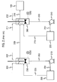
- Figure 2 is a schematic representation of a known prior art process for hydrolysis of acetone cyanohydrin with acid, provided for comparison.
- As discussed hereinabove, cyanohydrins are subject to decomposition when in the presence of strong acids at elevated temperatures, for example at temperatures greater than about 70°C, thereby resulting in reduced process yields. Furthermore, in the context of a hydrolysis reaction of acetone cyanohydrin ("ACH") with sulfuric acid, the decomposition of acetone cyanohydrin to acetone and hydrogen cyanide not only results in reducing the yield of hydrolysis products and, in turn, of the downstream MAA and MAA ester products, but it can also lead to additional complications in the hydrolysis system.
- For example, the hydrogen cyanide formed by decomposition of acetone cyanohydrin is rapidly hydrolyzed and converted to formamide in the hydrolysis reaction. Subsequently and at a slower rate, the formamide thermally cracks to form carbon monoxide (CO) gas and ammonium sulfate salt. Unless the product mixture is adequately degassed, the presence of CO may manifest itself as pump cavitation and may contribute to overall process and unit inoperability. Increases in the overall temperature of the process can aid in the degassing process, however, increased hydrolysis reaction temperature leads to increased the levels of decomposition of acetone cyanohydrin.
- Additionally, under the typical operating conditions described in Kirk-Othmer, Encyclopedia of Chemical Technology, acetone is sulfonated by sulfuric acid to a mixture of mono- and di-sulfonic acids. In the hydrolysis section, acetone monosulfonic acid ("AMSA") predominates and as the reaction progresses further, acetone disulfonic acid ("ADSA") increases and becomes predominant. This series of reactions is important because each sulfonation of acetone reaction is accompanied by the stoichiometric generation of water. As is well-known in the art and pointed out in US '093, where water is present in the hydrolysis reaction mixture it will react to convert SIBAM to HIBAM, which is more difficult and requires higher temperatures to convert to MAM in the subsequent cracking reaction.
- In a general embodiment, the method of the present invention for minimizing decomposition of cyanohydrins in an exothermic reaction process involving cyanohydrins, comprises the steps of providing a reaction medium to a tubular reactor and providing one or more reactants to the tubular reactor. The tubular reactor contains at least one reaction zone therein and has internal mixing means positioned in the at least one reaction zone. The method of the present invention further comprises mixing the reaction medium with the one or more reactants in the at least one reaction zone. This mixing forms a bulk reaction mixture having a substantially homogenous composition and a substantially homogenous reaction temperature. The method also comprises removing a quantity of heat from the exothermic reaction process, where the quantity of heat removed is equivalent to the quantity of heat produced by the exothermic reaction process. The quantities of heat removed and produced are equivalent, for purposes of the present invention, where the quantities are about equal to one another, within + or - 10%, or even for example, 1%. Lastly, the method of the present invention comprises the step of reacting the one or more reactants in the at least one reaction zone to produce a mixed product having a bulk temperature. The bulk temperature of the mixed product is optimally measured after the reaction has ceased (such as, for example, when substantially all of at least one of the one or more reactants has been reacted) and the mixed product has exited the tubular reactor.
- By an exothermic reaction process "involving cyanohydrins" it is meant that one or more of the reactants and products of the reaction processes comprise one or more cyanohydrins. Moreover, as will be recognized by persons of ordinary skill, an exothermic reaction is a reaction which produces a quantity of heat, where the quantity depends upon a number of factors, including but not limited to, the types and amounts of reactants and the temperature and duration of the reaction.
- The term "cyanohydrins" as used herein means compounds having the general formula:

- With respect to the tubular reactor, the method of the present invention includes embodiments wherein there is more than one tubular reactor, or even a plurality of tubular reactors (such as, for example, in a shell-and-tube type of reactor apparatus), used to perform the exothermic reaction process involving cyanohydrins. Where more than one tubular reactor is employed, at least one, and preferably all of the tubular reactors contain at least one reaction zone therein and have internal mixing means positioned in the at least one reaction zone.
- Moreover, the internal mixing means of the tubular reactor is at least one device selected from the group consisting of: static mixers comprising static mixing elements, orifice plates, venturis, jet mixers, eductors, perforated plates, spargers, agitators, rotary mixers, high-velocity circulation loops, and spray nozzles. The static mixing elements may be one or more elements selected from the group consisting of blades, pins, baffles, tabular inserts, and other shear-inducing devices. Such devices and static mixing elements are well known and commercially available from companies such as Koch-Glitsch, Inc. of Wichita, KS, Chemineer, Inc. of Dayton, OH, and Sulzer Chemtech Ltd. of Tulsa, OK.
- As will be recognized by persons of ordinary skill in the art, where the reaction process involves the use of corrosive substances (such as for example, sulfuric acid or caustic), the tubular reactor and its internal mixing means should be constructed of corrosion resistant materials, including but not limited to stainless steel (e.g., 300 series, 904L, 6-moly), tantalum, zirconium, and HASTELLOY® (e.g., B, B-2, B-3, C-22, and C-276).
- The reaction medium may be any material suitable for mixing with, containing, and transporting the reactants of the desired chemical reaction, without being consumed by the reaction, and will depend upon the nature of the desired chemical reaction and the required reactants. For example, without limitation, a suitable reaction medium may comprise the same types of compounds as are expected to be produced by the reaction process involving cyanohydrins. In fact, the reaction medium may be suitably comprised of captured and recycled products of the reaction process. Thus, in the case of a hydrolysis reaction of acetone cyanohydrin and sulfuric acid which is expected to produce SIBAM, HIBAM and MAM, the reaction medium could suitably comprise one or more of SIBAM, HIBAM and MAM. In some embodiments, the reaction medium may further comprise diluent materials, such as for example, hexane, sulfur dioxide, or straight-chain hydrocarbons.
- It is understood that one or more of the reactants (such as, for example, the acid in a hydrolysis reaction) may be provided indirectly to the tubular reactor by first adding one or more of the reactants to the reaction medium prior to providing the reaction medium to the tubular reactor.
- The one or more reactants used for the reaction process will depend upon the desired reaction and reaction products and it is well within the ability of persons of ordinary skill to select suitable reactants. For example, where it is desired to make SIBAM, HIBAM and MAM for further conversion to MAA and esters thereof, suitable reactants may be acetone cyanohydrin and an acid selected from the group consisting of sulfuric acid, oleum and mixtures thereof (as disclosed in US '093 discussed earlier hereinabove). Where acetone cyanohydrin is itself the desired product, the reactants may be acetone and hydrogen cyanide (as described in Kirk-Othmer, Encyclopedia of Chemical Technology), and a strong base, such as sodium hydroxide, may be present. In this reaction, water may also be present as a diluent, and the reaction may be typically performed between 0°C and 20°C, with elevated temperatures (greater than about 20°C) promoting cyanohydrin decomposition in this reaction system. Where it is desired to produce a particular cyanohydrin known as methyl ethyl ketone cyanohydrin, the reactants may be hydrocyanic acid and methyl ethyl ketone (as disclosed in U.S. Patent No. 6,743,938), and the reaction may be performed in the presence of a strong base, such as diethylamine. Thus, the cyanohydrin may be the reactant or the product in the reaction process and the method of the present invention may be advantageously applied to any such exothermic reaction process involving cyanohydrins.
- The step of mixing the reaction medium with the one or more reactants to form a bulk reaction mixture having a substantially homogenous composition and a substantially homogenous reaction temperature is accomplished, at least in part, in accordance with the present invention, by the use of the tubular reactor having internal mixing means described hereinabove.
- Another way to rapidly and thoroughly mix the reaction medium and one or more reactants to form a homogenous bulk reaction mixture, in accordance with the present invention, would be to provide at least one of the reactants to the tubular reactor at a plurality of points of addition, using a plurality of injector devices, such as without limitation, injector nozzles, that are positioned about the tubular reactor apparatus. The injector devices may be positioned about the tubular reactor circumferentially, longitudinally, or both. Moreover, all of the injector devices need not be used at any given time, but rather, at least one, and preferably more than one injector device should be in use to provide at least one of the reactants to the tubular reactor at various different points of addition. This arrangement serves to distribute the reactant more evenly into the reaction medium. In a particular embodiment of the present invention, the injection velocity of the reactant or reactants being provided through the injector devices may be the same at each injector device being used. Additionally, the injection velocity of the reactant(s) may be maintained, for example, without limitation, between 10 ft/see and 80 ft/sec (3m/sec and 24m/sec), or between 20 ft/sec and 65 ft/sec (6m/sec and 20m/sec), or even between 28 ft/sec and 42 ft/sec (8.5m/sec and 13m/sec), to achieve efficient mixing.
- It is also possible, in accordance with the present invention, to maintain optimal mixing efficiency using the injector devices by operating fewer injectors at lower overall production rates and, similarly, by operating more of the injector devices at higher production rates, rather than using the same number of injector devices at all times and adjusting the flow rate through each nozzle. The former procedure is believed to be better than the latter procedure because the latter procedure would result in variable injection velocities and, therefore, variable mixing efficiencies, at different locations within the reaction zones. For example, operating 10 injector devices at different injection velocities to achieve an overall reactant feed rate of 100 pounds per hour would create variable mixing conditions in the tubular reactor and a non-homogenous bulk reaction mixture.
Operating 10 injector devices each at 10 pounds per hour would achieve more uniform mixing and a more homogenous bulk reaction mixture. If a decision is made to decrease the production rate such that only a feed rate of 50 pounds per hour of reactant is required, then only 5 of the injector devices could be operated, each at the same 10 pounds per hour, while the other 5 injector devices are disabled or turned off, thus maintaining uniformity of mixing within the tubular reactor. It is believed that further optimization of the foregoing procedures, as well as the calculations and conversions required to determine the optimal injector operation procedure, are well within the ability of persons of ordinary skill in the art. - In a particular embodiment of the present invention, which is a hydrolysis reaction of acetone cyanohydrin with sulfuric acid, the addition rate of a reactant, such as acetone cyanohydrin, is controlled such that the temperature at the point of addition is never greater than the bulk temperature of the mixed product which leaves the tubular reactor. This serves to minimize, or even eliminate, the hot spots which may otherwise develop at the point of addition of the reactants through the injector devices.
- As with most exothermic reactions, the heat produced by the exothermic reaction process involving cyanohydrins must be removed in order to sustain the reaction process over time in a continuous steady state. The heat may be removed by cooling the tubular reactor, which will of course also cool the reaction zones and the bulk reaction mixture therein, using any conventional cooling means such as for example, any one or more of the following devices: shell-and-tube heat exchangers, spiral coolers, plate-and-frame exchangers, jacketed piping sections, and vessels with internal coiling coils or jacketing. It is possible to use turbulators in the tubes of shell-and-tube heat exchangers to improve cooling efficiency and/or resist fouling.
- In accordance with the present invention, heat may also be removed from the exothermic reaction process by cooling the reaction medium to a temperature between 1°C and 10°C less than the bulk temperature of the mixed product prior to providing the reaction medium to the tubular reactor. This aspect of the present invention results in the formation of a cooled bulk reaction mixture upon mixing the reactants with the reaction medium in the at least one reaction zone of the tubular reactor, which provides a cooler environment for the cyanohydrin, regardless of whether the cyanohydrin is a reactant that is added, or a product that is formed, in the reaction zone.
- Additionally, it is advantageous to remove heat from the cyanohydrins while they are in the at least one reaction zone with the reaction medium to minimize their decomposition. In accordance with the method of the present invention, this can be accomplished, at least in part, by providing an excess of reaction medium to the at least one reaction zone in comparison to the amount of reactants provided, whereupon the reaction medium becomes a heat sink and absorbs some of the heat from the cyanohydrins. For example, the reaction medium and the one or more reactants may be provided at a ratio of reaction medium:reactants of between 2:1 and 200:1, or between 3:1 and 100:1, or even between 4:1 to 40:1. It is noted that higher reaction medium:reactants ratios are better because they are believed to provide a larger heat sink capable of absorbing greater quantities of heat.
- In another embodiment of the present invention, one or more of the reactants may be cooled prior to being provided to the tubular reactor, for example, using separate heat exchangers (not shown).
- Where the exothermic reaction process involving cyanohydrins is a hydrolysis reaction of acetone cyanohydrin and sulfuric acid which produces a mixed product comprising SIBAM, HIBAM, and MAM, as previously discussed, for further reaction to produce MAA and esters thereof, the method may further comprise thermally converting the mixed product from the hydrolysis reaction in a cracker reactor to produce a cracker reactor mixture comprising methacrylamide and methacrylic acid. The cracker reactor mixture may then be reacted in at least one reactor with a material selected from alkanols and water to produce a monomer selected from methacrylic acid and esters thereof. Examples of suitable alkanols include but are not limited to methanol, ethanol, and butanol.
- In addition, to the foregoing features, it is possible for persons of ordinary skill in the art to recognize and develop many additions and modifications to the method of the present invention, all of which are intended to be within the scope of the invention. For example, where the exothermic reaction process is a hydrolysis reaction of acetone cyanohydrin with sulfuric acid, the reaction process may be a two stage system, i.e., having two tubular reactors and where the acetone cyanohydrin reactant feed is split between the two reactors, with between 50% and 95% of the acetone cyanohydrin reaction being provided to the first reactor, and the remainder to the second reactor.
- As might be recognized by persons of ordinary skill, the reaction processes involving cyanohydrins may also involve the need to transport and pump process streams which are highly viscous. One or more of the reaction medium and the mixed product may be transported and circulated through and between the process apparatus using high-viscosity service pumps, such as, but not limited to, Disc pumps (commercially available from Discflo Corporation of Santee, California), positive displacement pumps, or gear pumps. One or more of the reactants, such as the acid in a hydrolysis reaction, may be injected into the reaction medium prior to providing the reaction medium to the tubular reactor to provide higher localized mole ratios and to reduce the viscosity effects.
- Conditions in the reaction process, such as where the reaction process is a hydrolysis reaction of acetone cyanohydrin with sulfuric acid, may make degassing of the mixed product advantageous. In such circumstances, any conventional degassing means is suitable, including but not limited to, one or more devices selected from the group consisting of: impingement plates, coalescers, baffles, centrifugal separators (such as "Porta-Test Revolution" degassers, from NATCO Group, Inc. of Houston, TX), vacuum chambers, distributors, nozzles, throttling valves, flash tanks, settling chambers, ASP-type Degassing Pumps (commercially available from Yokota Manufacturing Co., Ltd. of Hiroshima, Japan), and the Kurabo In-line Degassing Device (available from Kurabo Industries Ltd. of Osaka, Japan).
- As would be easily determinable by persons of ordinary skill in the art, it may also be advantageous to add one or more polymerization inhibitors to the reaction process, such as, for example, to one or more of the reactants prior to providing them to the tubular reactor. Suitable polymerization inhibitors will depend, at least in part, upon the types of reactants and products involved in the reaction process. For example, where the exothermic reaction process is a hydrolysis reaction of acetone cyanohydrin with sulfuric acid, a suitable inhibitor would be include, although not limited to, phenothiazine.
- Furthermore, where the exothermic reaction process is a hydrolysis reaction of acetone cyanohydrin with sulfuric acid, the molar ratio of acid:acetone cyanohydrin present in the bulk reaction mixture is in the range of from 1.3:1 to 1.9:1
- These and other similar modifications will readily suggest themselves to those skilled in the art, and are intended to be encompassed within the spirit of the present invention disclosed herein and the scope of the appended claims.
- The following Examples provide comparative yields for two commercial-scale hydrolysis reaction processes operating at identical conditions. The results of these Examples demonstrate the yield advantage afforded by the method of the present invention over the prior art CSTR-based reaction processes involving cyanohydrins, particularly when applied to a hydrolysis reaction of acetone cyanohydrin with sulfuric acid. The compositions of the acetone cyanohydrin reactant and sulfuric acid reactant were the same for both Example 1 and Example 2.
- A first hydrolysis process ("Prior Art") of the type disclosed in Kirk-Othmer and US '093 is illustrated by Figure 2, and comprised two CSTR reactors in series. This system was operated at an H2SO4:ACH molar ratio of 1.48, and at a 2.3:1 ACH addition split, wherein 70% by weight of the total ACH feed was added to the first reaction stage, and 30% by weight of the total ACH feed was added to the second reaction stage. Sulfuric acid at a concentration of 99.5% and ACH at a concentration of 98.5% were utilized as reactants in this system.
- Specifically, the 1st reaction stage of the hydrolysis system employed in this example comprised a 1st
stage CSTR 230, acentrifugal pump 210, aheat exchanger 220, and associated 1st stage circulation piping (203,204,205).CSTR 230 comprised a 5000 gal (19 cubic meters) vessel and a dual-impeller, pitched-blade agitator for high-efficiency mixing of the reactor contents. Sub-surface ACH addition to the 1ststage CSTR 230 was provided via 201 using a first dip-pipe. Similarly, Sub-surface Sulfuric Acid addition to the 1ststage CSTR 230 was provided via 202 using a second dip-pipe. These dip-pipes served to direct the flow of reactants into the turbulent zone near the tip of the agitator blades in order to maximize efficiency of the mixing. PTZ inhibitor in acetone solution (not shown) was also added intoCSTR 230 to retard polymer formation. The temperature of the bulk liquid in the bottom ofCSTR 230 could be monitored using thermocouple T230. -
Stream 203 provides hydrolysis mix to Pump 210, which then circulated hydrolysis mix through the 1st stage circulation piping at a continuous rate of about 2.8 million lbs/hr (i.e., 4000 gpm, 15,140 liters/min).Stream 204 conveyed the hydrolysis mix from the discharge ofpump 210 toheat exchanger 220, where it was cooled.Heat exchanger 220 was a shell-and-tube type exchanger, with the process flow (hydrolysis mix) passing through the shell side and a nominal 60 °C tempered water flow passing through the tube side. Cooled hydrolysis mix exited the heat exchanger viastream 205 and was returned toCSTR 230. Gases removed from the hydrolysis mix were vented to a process flare header (not shown) for disposal. Degassed hydrolysis mix overflowed from the side ofCSTR 230 and was conveyed forward to the 2nd reaction stage viastream 209. - The 2nd reaction stage of the hydrolysis system employed in this example comprised a 2nd
stage CSTR 260, acentrifugal pump 240, aheat exchanger 250, and associated 2nd stage circulation piping (213,214,215).CSTR 260 comprised a 5000 gal (19 cubic meters) vessel and a dual-impeller, pitched-blade agitator for high-efficiency mixing of the reactor contents. Sub-surface ACH addition to the 2ndstage CSTR 230 was provided via 211 using a first dip-pipe. Optional Sub-surface Sulfuric Acid (212) addition to the 2ndstage CSTR 230 was not used in this example. As with the 1st stage CSTR dip-pipes, these 2nd stage dip-pipes served to direct the flow of reactants into the turbulent zone near the tip of the agitator blades in order to maximize efficiency of the mixing. The temperature of the bulk liquid in the bottom ofCSTR 260 could be monitored using thermocouple T260. -
Stream 213 provided hydrolysis mix to Pump 240, which then circulated hydrolysis mix through the 2nd stage circulation piping at a continuous rate of about 4.2 million lbs/hr (i.e., 6000 gpm, 22,700 liters/min).Stream 214 conveyed the hydrolysis mix from the discharge ofpump 240 toheat exchanger 250, where it was cooled.Heat exchanger 250 was a shell-and-tube type exchanger, with the process flow (hydrolysis mix) passing through the shell side and a nominal 65 °C tempered water flow passing through the tube side. Cooled hydrolysis mix exited the heat exchanger viastream 215 and was returned toCSTR 260. Gases removed from the hydrolysis mix were vented to a process flare header (not shown) for disposal. Degassed hydrolysis mix overflowed from the side ofCSTR 260 and was conveyed forward to the cracker reactor (100) viaStream 219. - In this example, the bulk temperature of the reaction mixture exiting the 1st reaction stage CSTR (230), as measured by thermocouple T230, was held constant at 85°C; the bulk temperature of the reaction mixture exiting the 2nd reaction stage CSTR (260), as measured by thermocouple T260, was held constant at 101°C.
- Under steady state conditions, samples of the final hydrolysis mix were collected from
stream 219 using well-insulated sample containers (Thermos™ brand vacuum bottles). - An aliquot (~10 g) of the representative Hydrolysis mix was removed and placed in a tared jar containing a stir bar and its weight was recorded. Methanesulfonic acid (99.5% purity, ~3 g, from Aldrich Chemical Company) was added as an internal standard via a syringe and the weights were all recorded. The mixture was stirred in a constant temperature water bath at 60°C for 40 min. An aliquot (~0.2 g) of the resulting mixture was removed and placed in an NMR tube and diluted with deuterated nitromethane (CD3NO2, from Aldrich Chemical Company). The clear and homogeneous mixture was analyzed by NMR on a Varian Inova 500 Instrument.
- The total molar yield of SIBAM, HIBAM and MAM produced by the foregoing process is reported in Table 1.
- An improved hydrolysis system ("Inventive"), in accordance with the method of the present invention, is illustrated in Figure 1 and comprised two continuous flow reaction stages. This system was operated under the same conditions used for the CSTR-based hydrolysis system of the preceding Example 1.
- Specifically, this improved hydrolysis system was operated at an H2SO4:ACH molar ratio of 1.48, and at a 2.3:1 ACH addition split, wherein 70% by weight of the total ACH feed was added to the first reaction stage and 30% by weight of the total ACH feed was added to the second reaction stage. As in the previous example, Sulfuric acid at a concentration of 99.5% and ACH at a concentration of 98.5% were utilized as reactants.
- The 1st reaction stage of the hydrolysis system employed in this example comprised an
ACH mixing apparatus 10, adegassing apparatus 20, acentrifugal pump 30, aheat exchanger 40, and associated 1st stage circulation piping (3,4,5,7,8). Sulfuric Acid (6) was added into the hydrolysis mix instream 5 through a mixing tee.Stream 5 provided hydrolysis mix to Pump 30, which then circulated hydrolysis mix through the 1st stage circulation piping at a continuous rate of about 2.5million lbs/hr (i.e., 3500gpm, 13,250 liters/min).Stream 7 conveyed the hydrolysis mix from the discharge ofpump 30 toheat exchanger 40, where it was cooled.Heat exchanger 40 was a shell-and-tube type exchanger, with the process flow (hydrolysis mix) passing through the shell side and a nominal 60 °C tempered water flow passing through the tube side. Cooled hydrolysis mix exited the heat exchanger viastream 8. The temperature of the cooled hydrolysis mix could be monitored using thermocouple T8. The hydrolysis mix then entered theACH mixing apparatus 10, wherein ACH was added into the hydrolysis mix stream. TheACH mixing apparatus 10 comprised a single static mixing unit consisting of four Koch SMXL mixing elements (available from Koch-Glitsch, Inc. of Wichita, Kansas) installed in series within a 12" diameter piping section. The static mixing unit was approximately 190 inches in length. TheACH mixing apparatus 10 further comprised two sets of ACH injectors: a first set of four injectors (1) located at a distance of about 30" from the inlet end of the mixing apparatus and a second set of four injectors (2) located at a distance of about 45" from the inlet end of the mixing element. Each of the four injectors in a set were evenly-spaced along the circumference of the pipe section - e.g., one injector each positioned at 0°, 90°, 180°, and 270° relative to the pipe section centerline. Each injector comprised a 0.290" internal diameter orifice, flush-mounted to the piping section wall, through which liquid ACH flowed at a velocity of about 36 feet per second (11 meters per second) into the static mixing unit. At this velocity, a jet of ACH was produced having sufficient kinetic energy to traverse from the pipe section wall toward the centerline of the static mixing unit, thereby ensuring rapid and efficient mixing. For the operating rate of this specific example, six of the eight injectors were utilized: all four of the first set of injectors and two of the second set of injectors. Of the injectors in operation, all were operated at the same ACH flow rate. As a result of the exothermic ACH hydrolysis reaction, the hydrolysis mix warmed within the ACH mixing apparatus. The warm hydrolysis mix exited the ACH mixing apparatus viastream 3 and entered thedegassing apparatus 20. PTZ inhibitor in acetone solution (9) was added into thehydrolysis mix stream 3 to retard polymer formation. -
Degassing apparatus 20 comprised an unagitated 5,600 gallon (21 cubic meters) degassing vessel in which was installed a "Porta-Test Revolution" model centrifugal gas/liquid separator (designed and manufactured by NATCO Group, Inc. of Houston, Texas). Gases removed from the hydrolysis mix were vented to a process flare header (not shown) for disposal; the degassed hydrolysis mix collected as a bulk liquid in the bottom of the degassing vessel. The temperature of the bulk liquid in the bottom of the degassing vessel could be monitored using thermocouple T20. Degassed hydrolysis mix was withdrawn from the bottom of the degassing vessel and was divided into two streams:stream 49 conveyed a first portion of the hydrolysis mix forward to the 2nd reaction stage, whilestream 5 returned a second portion of the hydrolysis mix tocentrifugal pump 30 to maintain the 1st stage circulation. - The 2nd reaction stage of the inventive hydrolysis system employed in this example comprised an
ACH mixing apparatus 50, adegassing apparatus 60, acentrifugal pump 70, aheat exchanger 80, and associated 2nd stage circulation piping (13,14,15,17,18). Hydrolysis mix fromstream 49 entered the 2nd stage and was combined with the hydrolysis mix instream 15. In this specific example, optional sulfuric acid (16) was not added.Stream 15 provided hydrolysis mix to Pump 70, which then circulated hydrolysis mix through the 2nd stage circulation piping at a continuous rate of about 2.2 million lbs/hr (i.e., 3000gpm, 11,360 liters/min).Stream 17 conveyed the hydrolysis mix from the discharge ofpump 70 toheat exchanger 80, where it was cooled.Heat exchanger 80 was a shell-and-tube type exchanger, with the process flow (hydrolysis mix) passing through the tube side and a nominal 70 °C tempered water flow passing through the shell side. Cooled hydrolysis mix exited the heat exchanger viastream 18. The temperature of the cooled hydrolysis mix could be monitored using thermocouple T18. The hydrolysis mix then entered theACH mixing apparatus 50, wherein ACH was added into the hydrolysis mix stream. TheACH mixing apparatus 50 comprised a single static mixing unit consisting of four Koch SMXL mixing elements installed in series within a 12" diameter piping section. The static mixing unit was approximately 210 inches in length. TheACH mixing apparatus 50 further comprised two sets of ACH injectors: a first set of four injectors (1) located at a distance of about 30" from the inlet end of the mixing apparatus and a second set of four injectors (2) located at a distance of about 45" from the inlet end of the mixing element. Each of the four injectors in a set were evenly-spaced along the circumference of the pipe section - e.g., one injector each positioned at 0°, 90°, 180°, and 270° relative to the pipe section centerline. Each injector comprised a 0.175" internal diameter orifice, flush-mounted to the piping section wall, through which liquid ACH flowed at a velocity of about 62 feet per second (19 meters per second) into the static mixing unit. At this velocity, a jet of ACH was produced having sufficient kinetic energy to traverse from the pipe section wall toward the centerline of the static mixing unit, thereby ensuring rapid and efficient mixing. For the operating rate of this specific example, only the first set of four injectors were utilized; of the injectors in operation, all were operated at the same ACH flow rate. As a result of the exothermic ACH hydrolysis reaction, the hydrolysis mix warmed within the ACH mixing apparatus. The warm hydrolysis mix exited the ACH mixing apparatus viastream 13 and entered thedegassing apparatus 60. In this specific example, optional PTZ inhibitor in acetone solution (19) was not added. -
Degassing apparatus 60 comprised an unagitated 10,900 gallon (41 cubic meters) degassing vessel in which was installed a "Porta-Test Revolution" model centrifugal gas/liquid separator (designed and manufactured by NATCO Group, Inc. of Houston, Texas). Gases removed from the hydrolysis mix were vented to a process flare header (not shown) for disposal; the degassed hydrolysis mix collected as a bulk liquid in the bottom of the degassing vessel. The temperature of the bulk liquid in the bottom of the degassing vessel could be monitored using thermocouple T60. Degassed hydrolysis mix was withdrawn from the bottom of the degassing vessel (14) and was divided into two streams:stream 99 conveyed a first portion of the hydrolysis mix forward to the cracker reactor (100), whilestream 15 returned a second portion of the hydrolysis mix tocentrifugal pump 70 to maintain the 2nd stage circulation. - In this example, the bulk temperature of the reaction mixture exiting the 1st stage degassing apparatus (20), as measured by thermocouple T20, was held constant at 85°C; the bulk temperature of the reaction mixture exiting the 2nd stage degassing apparatus (60), as measured by thermocouple T60, was held constant at 101 °C.
- Under steady state conditions, samples of the final hydrolysis mix were collected from
stream 99 using well-insulated sample containers (Thermos™ brand vacuum bottles). - As in the previous example, the hydrolysis mix sample was acidified, diluted, and analyzed by NMR. The total molar yield of SIBAM, HIBAM and MAM produced by the foregoing inventive method is reported in Table 1.
Table 1 Hydrolysis System Stream Temperature at ACH Feed point Residence Time ACH Molar Yield (%) 1 st stage 2 nd stage Example 1 (Prior Art CSTR) (Figure 2) 85 °C (T230) 101 °C (T260) 40 minutes 95.23 ±0.60 Example 2 (Inventive Method) (Figure 1) 79°C (T8) 100°C (T18) 110 minutes 96.01 ±0.22
Claims (11)
- A method for minimizing decomposition of cyanohydrins in an exothermic reaction process involving cyanohydrins and which produces a quantity of heat, said method comprising the steps of:(a) providing a reaction medium to a tubular reactor containing at least one reaction zone therein and having internal mixing means positioned in said at least one reaction zone;(b) providing one or more reactants to said tubular reactor;(c) mixing said reaction medium with said one or more reactants in said at least one reaction zone, thereby forming a bulk reaction mixture having a substantially homogenous composition and a substantially homogenous reaction temperature;(d) removing a quantity of heat from the exothermic reaction process, said quantity of heat being equivalent to said quantity of heat produced by the exothermic reaction process; and(e) reacting said one or more reactants in said at least one reaction zone to produce a mixed product having a bulk temperature.
- The method of Claim 1, wherein the step of removing a quantity of heat is performed by cooling said reaction medium to a temperature between 1°C and 10°C less than said bulk temperature prior to providing said reaction medium to said tubular reactor.
- The method of Claim 1, wherein said reaction medium and said one or more reactants are provided at a ratio of reaction medium:reactants of between 2:1 and 200:1.
- The method of Claim 1, wherein at least a first one of said one or more reactants is provided to said tubular reactor in at least one of a plurality of points of addition by a plurality of injector devices positioned circumferentially about said tubular reactor apparatus.
- The method of Claim 4, wherein the step of mixing said reaction medium with said one or more reactants is accomplished, at least in part, by selecting and using one or more of said plurality of injector devices to provide said at least a first one of said one or more reactants to said tubular reactor.
- The method of Claim 1, wherein at least a second one of said one or more reactants is provided indirectly to said tubular reactor by first adding said at least a second one of said one or more reactants to said reaction medium prior to providing said reaction medium to said tubular reactor.
- The method of Claim 1, wherein said internal mixing means is at least one device selected from the group consisting of: static mixers, orifice plates, venturis, jet mixers, eductors, perforated plates, spargers, agitators, rotary mixers, high-velocity circulation loops, and spray nozzles.
- The method of Claim 1, wherein said tubular reactor comprises at least two tubular reactors.
- The method of Claim 1, wherein said reaction process involving cyanohydrins is a hydrolysis reaction, a first reactant comprises acetone cyanohydrin, and a second reactant comprises an acid selected from the group consisting of: sulfuric acid, oluem and mixtures thereof.
- The method of Claim 9, wherein the molar ratio of acid:acetone cyanohydrin present in the bulk reaction mixture is in the range of from 1.3:1 to 1.9:1.
- The method of Claim 9, wherein said mixed product of said hydrolysis reaction comprises one or more products selected from the group consisting of: α-sulfatoisobutyramide, α-hydroxyisobutyramide, and methacrylamide; said method further comprising the steps of:(f) thermally converting the mixed product from the hydrolysis reaction in a cracker reactor to produce a cracker reactor mixture comprising methacrylamide and methacrylic acid; and(g) reacting the cracker reactor mixture in at least one reactor with a material selected from alkanol and water to produce a monomer selected from methacrylic acid and esters thereof.
Applications Claiming Priority (1)
| Application Number | Priority Date | Filing Date | Title |
|---|---|---|---|
| US63087204P | 2004-11-24 | 2004-11-24 |
Publications (2)
| Publication Number | Publication Date |
|---|---|
| EP1666451A1 true EP1666451A1 (en) | 2006-06-07 |
| EP1666451B1 EP1666451B1 (en) | 2007-12-19 |
Family
ID=35976758
Family Applications (1)
| Application Number | Title | Priority Date | Filing Date |
|---|---|---|---|
| EP05257081A Expired - Lifetime EP1666451B1 (en) | 2004-11-24 | 2005-11-17 | Improved process for chemical reactions involving cyanohydrins |
Country Status (9)
| Country | Link |
|---|---|
| US (2) | US7582790B2 (en) |
| EP (1) | EP1666451B1 (en) |
| JP (1) | JP5015447B2 (en) |
| KR (1) | KR100724716B1 (en) |
| CN (1) | CN100363335C (en) |
| BR (1) | BRPI0505097B1 (en) |
| DE (1) | DE602005003912T2 (en) |
| ES (1) | ES2297637T3 (en) |
| TW (1) | TWI277444B (en) |
Cited By (9)
| Publication number | Priority date | Publication date | Assignee | Title |
|---|---|---|---|---|
| WO2008068065A1 (en) * | 2006-12-08 | 2008-06-12 | Evonik Röhm Gmbh | Process for preparing cyanohydrins and their use in the preparation of alkyl esters of methacrylic acid |
| WO2009115349A1 (en) | 2008-03-20 | 2009-09-24 | Evonik Röhm Gmbh | Method for producing methacrylic acid |
| DE102008000787A1 (en) | 2008-03-20 | 2009-09-24 | Evonik Röhm Gmbh | Process for the purification of methacrylic acid |
| WO2010121882A1 (en) | 2009-04-23 | 2010-10-28 | Evonik Röhm Gmbh | Metering ring |
| US8143434B2 (en) | 2006-12-14 | 2012-03-27 | Evonik Röhm Gmbh | Production by distillation of acetone cyanhydrin and method for producing methacrylic ester and subsequent products |
| DE102012205257A1 (en) | 2012-03-30 | 2013-10-02 | Evonik Röhm Gmbh | Process for the hydrolysis of acetocyanohydrin |
| WO2022084032A1 (en) | 2020-10-23 | 2022-04-28 | Röhm Gmbh | Optimized process for synthesizing alkyl methacrylate by reducing unwanted byproducts |
| WO2022084274A1 (en) | 2020-10-23 | 2022-04-28 | Röhm Gmbh | Optimized process for synthesizing methacrylic acid (maa) and/or alkyl methacrylate by reducing unwanted byproducts |
| WO2022157796A1 (en) * | 2021-01-23 | 2022-07-28 | Jhaveri Devang | A method of chemical reaction in a heat exchanger reactor. |
Families Citing this family (13)
| Publication number | Priority date | Publication date | Assignee | Title |
|---|---|---|---|---|
| HU3201U (en) * | 2006-02-08 | 2006-12-28 | Csokai Viktor Dr | Apparatus for recycling of pvc |
| DE102006059511A1 (en) * | 2006-12-14 | 2008-06-19 | Evonik Röhm Gmbh | Process for the preparation of acetone cyanohydrin and its derivatives by controlled cooling |
| DE102007050284A1 (en) * | 2007-10-18 | 2009-04-23 | Evonik Röhm Gmbh | Process for amidation of nitriles in the presence of sulfuric acid |
| JP5876978B2 (en) * | 2007-10-23 | 2016-03-02 | 日宝化学株式会社 | Method for producing cyanohydrin compound and method for producing α-hydroxyester compound |
| US8685175B2 (en) * | 2009-09-16 | 2014-04-01 | Uop Llc | Apparatus and process for isomerizing a hydrocarbon stream |
| US8795354B2 (en) | 2010-03-05 | 2014-08-05 | Edwards Lifesciences Corporation | Low-profile heart valve and delivery system |
| JP6088058B2 (en) * | 2012-09-28 | 2017-03-01 | ローム アンド ハース カンパニーRohm And Haas Company | Process for producing MMA and / or MAA from acetone cyanohydrin and sulfuric acid |
| TWI637935B (en) * | 2013-07-16 | 2018-10-11 | 日商三菱瓦斯化學股份有限公司 | Method for producing α-hydroxyisobutylamidine and reaction device |
| FR3008627B1 (en) | 2013-07-19 | 2017-02-24 | Arkema France | THERMAL CONVERSION TANK USED IN ACETONE CYANOHYDRIN AMIDIFICATION PROCESS |
| FR3012143B1 (en) * | 2013-10-18 | 2016-08-26 | Arkema France | HYDROLYSIS TANK IN ACETONE CYANOHYDRIN AMIDIFICATION PROCESS |
| CN106588650B (en) * | 2016-03-25 | 2020-04-17 | 中国石油集团东北炼化工程有限公司吉林设计院 | Method and system for feeding acetone cyanohydrin in methyl methacrylate preparation process |
| WO2019234524A1 (en) * | 2018-06-04 | 2019-12-12 | Sabic Global Technologies B.V. | Dimerization of cyclopentadiene using reactive jet mixing |
| CN108864420B (en) * | 2018-08-17 | 2023-11-21 | 沧州骏驰新材料科技有限公司 | Continuous esterification production process of allyl polyether |
Citations (6)
| Publication number | Priority date | Publication date | Assignee | Title |
|---|---|---|---|---|
| DE765734C (en) * | 1941-12-04 | 1952-12-22 | Roehm & Haas G M B H | Process for the preparation of methacrylic acid compounds |
| GB943536A (en) * | 1958-12-09 | 1963-12-04 | Ludwig Huter | Process for the production of methacrylic acid derivatives |
| EP0226724A1 (en) * | 1985-11-22 | 1987-07-01 | Degussa Aktiengesellschaft | Process for the production of methacrylamide |
| US5763687A (en) | 1995-12-15 | 1998-06-09 | Mitsui Chemicals, Inc. | Preparation process for aromatic mononitro compounds |
| US20030208093A1 (en) | 2002-05-01 | 2003-11-06 | Carlson Curtis Ingstad | Process for methacrylic acid and methacrylic acid ester production |
| US6743938B1 (en) | 1999-07-29 | 2004-06-01 | Atofina | Method for making ethyl ketone cyanohydrin |
-
2005
- 2005-11-07 US US11/268,372 patent/US7582790B2/en active Active
- 2005-11-14 TW TW094139853A patent/TWI277444B/en not_active IP Right Cessation
- 2005-11-17 EP EP05257081A patent/EP1666451B1/en not_active Expired - Lifetime
- 2005-11-17 ES ES05257081T patent/ES2297637T3/en not_active Expired - Lifetime
- 2005-11-17 DE DE602005003912T patent/DE602005003912T2/en not_active Expired - Lifetime
- 2005-11-18 KR KR1020050110529A patent/KR100724716B1/en not_active Expired - Fee Related
- 2005-11-18 BR BRPI0505097-9A patent/BRPI0505097B1/en active IP Right Grant
- 2005-11-21 CN CNB2005101271073A patent/CN100363335C/en not_active Expired - Lifetime
- 2005-11-22 JP JP2005337012A patent/JP5015447B2/en not_active Expired - Lifetime
-
2008
- 2008-09-18 US US12/284,028 patent/US7763746B2/en not_active Expired - Lifetime
Patent Citations (6)
| Publication number | Priority date | Publication date | Assignee | Title |
|---|---|---|---|---|
| DE765734C (en) * | 1941-12-04 | 1952-12-22 | Roehm & Haas G M B H | Process for the preparation of methacrylic acid compounds |
| GB943536A (en) * | 1958-12-09 | 1963-12-04 | Ludwig Huter | Process for the production of methacrylic acid derivatives |
| EP0226724A1 (en) * | 1985-11-22 | 1987-07-01 | Degussa Aktiengesellschaft | Process for the production of methacrylamide |
| US5763687A (en) | 1995-12-15 | 1998-06-09 | Mitsui Chemicals, Inc. | Preparation process for aromatic mononitro compounds |
| US6743938B1 (en) | 1999-07-29 | 2004-06-01 | Atofina | Method for making ethyl ketone cyanohydrin |
| US20030208093A1 (en) | 2002-05-01 | 2003-11-06 | Carlson Curtis Ingstad | Process for methacrylic acid and methacrylic acid ester production |
Non-Patent Citations (3)
| Title |
|---|
| KIRK-OTHMER: "ENCYCLOPEDIA OF CHEMICAL TECHNOLOGY" |
| KIRK-OTHMER: "ENCYCLOPEDIA OF CHEMICAL TECHNOLOGY", vol. 16, 1995, JOHN WILEY & SONS, pages: 16 - 18 |
| R. WILCZYNSKI ET AL: "Kirk-Othmer Encyclopedia of Chemical Technology", 2003, JOHN WILEY & SONS, INC., XP002372018 * |
Cited By (18)
| Publication number | Priority date | Publication date | Assignee | Title |
|---|---|---|---|---|
| RU2497805C2 (en) * | 2006-12-08 | 2013-11-10 | Эвоник Рем ГмбХ | Method of obtaining acetonecyanohydrin |
| WO2008068065A1 (en) * | 2006-12-08 | 2008-06-12 | Evonik Röhm Gmbh | Process for preparing cyanohydrins and their use in the preparation of alkyl esters of methacrylic acid |
| EP2054378B1 (en) | 2006-12-08 | 2016-02-17 | Evonik Röhm GmbH | Process for preparing cyanohydrins and their use in the preparation of alkyl esters of methacrylic acid |
| US8129559B2 (en) | 2006-12-08 | 2012-03-06 | Evonik Röhm Gmbh | Process for preparing cyanohydrins and their use in the preparation of alkyl esters of methacrylic acid |
| KR101420462B1 (en) * | 2006-12-08 | 2014-07-16 | 에보니크 룀 게엠베하 | Process for preparing cyanohydrins and their use in the preparation of alkyl esters of methacrylic acid |
| TWI414509B (en) * | 2006-12-08 | 2013-11-11 | Evonik Roehm Gmbh | Process for preparing cyanohydrins and their use in the preparation of alkyl methacrylates |
| US8143434B2 (en) | 2006-12-14 | 2012-03-27 | Evonik Röhm Gmbh | Production by distillation of acetone cyanhydrin and method for producing methacrylic ester and subsequent products |
| RU2495868C2 (en) * | 2006-12-14 | 2013-10-20 | Эвоник Рем ГмбХ | Distillation processing of acetone cyanohydrin and method of producing alkyl esters of methacrylic acid and derivatives |
| WO2009115349A1 (en) | 2008-03-20 | 2009-09-24 | Evonik Röhm Gmbh | Method for producing methacrylic acid |
| DE102008000785A1 (en) | 2008-03-20 | 2009-09-24 | Evonik Röhm Gmbh | Process for the preparation of methacrylic acid |
| DE102008000787A1 (en) | 2008-03-20 | 2009-09-24 | Evonik Röhm Gmbh | Process for the purification of methacrylic acid |
| WO2010121882A1 (en) | 2009-04-23 | 2010-10-28 | Evonik Röhm Gmbh | Metering ring |
| DE102009002592A1 (en) | 2009-04-23 | 2010-10-28 | Evonik Röhm Gmbh | Dosage |
| WO2013143812A1 (en) | 2012-03-30 | 2013-10-03 | Evonik Röhm Gmbh | Method for hydrolysing acetone cyanohydrin |
| DE102012205257A1 (en) | 2012-03-30 | 2013-10-02 | Evonik Röhm Gmbh | Process for the hydrolysis of acetocyanohydrin |
| WO2022084032A1 (en) | 2020-10-23 | 2022-04-28 | Röhm Gmbh | Optimized process for synthesizing alkyl methacrylate by reducing unwanted byproducts |
| WO2022084274A1 (en) | 2020-10-23 | 2022-04-28 | Röhm Gmbh | Optimized process for synthesizing methacrylic acid (maa) and/or alkyl methacrylate by reducing unwanted byproducts |
| WO2022157796A1 (en) * | 2021-01-23 | 2022-07-28 | Jhaveri Devang | A method of chemical reaction in a heat exchanger reactor. |
Also Published As
| Publication number | Publication date |
|---|---|
| US20090082587A1 (en) | 2009-03-26 |
| CN100363335C (en) | 2008-01-23 |
| KR20060058012A (en) | 2006-05-29 |
| TW200624162A (en) | 2006-07-16 |
| CN1778791A (en) | 2006-05-31 |
| BRPI0505097A (en) | 2006-07-04 |
| TWI277444B (en) | 2007-04-01 |
| EP1666451B1 (en) | 2007-12-19 |
| JP2006143732A (en) | 2006-06-08 |
| DE602005003912T2 (en) | 2008-12-04 |
| JP5015447B2 (en) | 2012-08-29 |
| US7763746B2 (en) | 2010-07-27 |
| DE602005003912D1 (en) | 2008-01-31 |
| US7582790B2 (en) | 2009-09-01 |
| BRPI0505097B1 (en) | 2020-12-01 |
| US20060111586A1 (en) | 2006-05-25 |
| ES2297637T3 (en) | 2008-05-01 |
| KR100724716B1 (en) | 2007-06-04 |
Similar Documents
| Publication | Publication Date | Title |
|---|---|---|
| US7763746B2 (en) | Process for chemical reactions involving cyanohydrins | |
| US7253307B1 (en) | Process for production of methacrylic acid | |
| US20100036152A1 (en) | Continuous Method for Producing Acyl Peroxides | |
| US8334399B2 (en) | Method for producing acetone cyanohydrin and the subsequent products thereof by specific cooling | |
| RU2495868C2 (en) | Distillation processing of acetone cyanohydrin and method of producing alkyl esters of methacrylic acid and derivatives | |
| US20100029881A1 (en) | Method for producing methacrylic alkyl esters by way of azeotropic distillation | |
| TWI414509B (en) | Process for preparing cyanohydrins and their use in the preparation of alkyl methacrylates | |
| EP0477358B1 (en) | Turbulent flow process and monoalkyl aromatic production | |
| CN218981525U (en) | Continuous flow synthesis system of nitromethane | |
| CN104768920B (en) | By acetone cyanohydrin and the method for gas washing in SA production MMA and/or MAA | |
| CN119912409A (en) | Closed-loop reaction method and system for continuous production of glycidyl methacrylate | |
| HK1120028B (en) | Process for preparing acetone cyanohydrin and its conversion products by controlled cooling | |
| HK1120024A (en) | Process for preparing cyanohydrins and their use in the preparation of alkyl esters of methacrylic adcid | |
| HK1119657B (en) | Process for preparing alkyl methacrylates by azeotropic distillation | |
| HK1120027B (en) | Distillative workup of acetone cyanohydrin and process for preparing methacrylate and conversion products |
Legal Events
| Date | Code | Title | Description |
|---|---|---|---|
| PUAI | Public reference made under article 153(3) epc to a published international application that has entered the european phase |
Free format text: ORIGINAL CODE: 0009012 |
|
| 17P | Request for examination filed |
Effective date: 20051122 |
|
| AK | Designated contracting states |
Kind code of ref document: A1 Designated state(s): AT BE BG CH CY CZ DE DK EE ES FI FR GB GR HU IE IS IT LI LT LU LV MC NL PL PT RO SE SI SK TR |
|
| AX | Request for extension of the european patent |
Extension state: AL BA HR MK YU |
|
| AKX | Designation fees paid |
Designated state(s): DE ES FR GB IT |
|
| GRAP | Despatch of communication of intention to grant a patent |
Free format text: ORIGINAL CODE: EPIDOSNIGR1 |
|
| GRAS | Grant fee paid |
Free format text: ORIGINAL CODE: EPIDOSNIGR3 |
|
| GRAA | (expected) grant |
Free format text: ORIGINAL CODE: 0009210 |
|
| AK | Designated contracting states |
Kind code of ref document: B1 Designated state(s): DE ES FR GB IT |
|
| REG | Reference to a national code |
Ref country code: GB Ref legal event code: FG4D |
|
| REF | Corresponds to: |
Ref document number: 602005003912 Country of ref document: DE Date of ref document: 20080131 Kind code of ref document: P |
|
| REG | Reference to a national code |
Ref country code: ES Ref legal event code: FG2A Ref document number: 2297637 Country of ref document: ES Kind code of ref document: T3 |
|
| ET | Fr: translation filed | ||
| PLBI | Opposition filed |
Free format text: ORIGINAL CODE: 0009260 |
|
| PLAX | Notice of opposition and request to file observation + time limit sent |
Free format text: ORIGINAL CODE: EPIDOSNOBS2 |
|
| 26 | Opposition filed |
Opponent name: EVONIK ROEHM GMBH Effective date: 20080919 |
|
| PLAF | Information modified related to communication of a notice of opposition and request to file observations + time limit |
Free format text: ORIGINAL CODE: EPIDOSCOBS2 |
|
| PLAF | Information modified related to communication of a notice of opposition and request to file observations + time limit |
Free format text: ORIGINAL CODE: EPIDOSCOBS2 |
|
| PLBB | Reply of patent proprietor to notice(s) of opposition received |
Free format text: ORIGINAL CODE: EPIDOSNOBS3 |
|
| REG | Reference to a national code |
Ref country code: ES Ref legal event code: FD2A Effective date: 20081118 |
|
| PG25 | Lapsed in a contracting state [announced via postgrant information from national office to epo] |
Ref country code: ES Free format text: LAPSE BECAUSE OF NON-PAYMENT OF DUE FEES Effective date: 20081118 |
|
| PLAB | Opposition data, opponent's data or that of the opponent's representative modified |
Free format text: ORIGINAL CODE: 0009299OPPO |
|
| PLCK | Communication despatched that opposition was rejected |
Free format text: ORIGINAL CODE: EPIDOSNREJ1 |
|
| PLAB | Opposition data, opponent's data or that of the opponent's representative modified |
Free format text: ORIGINAL CODE: 0009299OPPO |
|
| PLAB | Opposition data, opponent's data or that of the opponent's representative modified |
Free format text: ORIGINAL CODE: 0009299OPPO |
|
| R26 | Opposition filed (corrected) |
Opponent name: EVONIK ROEHM GMBH Effective date: 20080919 |
|
| R26 | Opposition filed (corrected) |
Opponent name: EVONIK ROEHM GMBH Effective date: 20080919 |
|
| R26 | Opposition filed (corrected) |
Opponent name: EVONIK ROEHM GMBH Effective date: 20080919 |
|
| APBM | Appeal reference recorded |
Free format text: ORIGINAL CODE: EPIDOSNREFNO |
|
| APBP | Date of receipt of notice of appeal recorded |
Free format text: ORIGINAL CODE: EPIDOSNNOA2O |
|
| APAH | Appeal reference modified |
Free format text: ORIGINAL CODE: EPIDOSCREFNO |
|
| PGFP | Annual fee paid to national office [announced via postgrant information from national office to epo] |
Ref country code: IT Payment date: 20081130 Year of fee payment: 4 |
|
| APBQ | Date of receipt of statement of grounds of appeal recorded |
Free format text: ORIGINAL CODE: EPIDOSNNOA3O |
|
| APBU | Appeal procedure closed |
Free format text: ORIGINAL CODE: EPIDOSNNOA9O |
|
| PLBN | Opposition rejected |
Free format text: ORIGINAL CODE: 0009273 |
|
| STAA | Information on the status of an ep patent application or granted ep patent |
Free format text: STATUS: OPPOSITION REJECTED |
|
| 27O | Opposition rejected |
Effective date: 20120612 |
|
| REG | Reference to a national code |
Ref country code: DE Ref legal event code: R100 Ref document number: 602005003912 Country of ref document: DE Effective date: 20120612 |
|
| REG | Reference to a national code |
Ref country code: FR Ref legal event code: PLFP Year of fee payment: 11 |
|
| REG | Reference to a national code |
Ref country code: FR Ref legal event code: PLFP Year of fee payment: 12 |
|
| REG | Reference to a national code |
Ref country code: FR Ref legal event code: PLFP Year of fee payment: 13 |
|
| REG | Reference to a national code |
Ref country code: FR Ref legal event code: PLFP Year of fee payment: 14 |
|
| P01 | Opt-out of the competence of the unified patent court (upc) registered |
Effective date: 20230525 |
|
| PGFP | Annual fee paid to national office [announced via postgrant information from national office to epo] |
Ref country code: GB Payment date: 20240926 Year of fee payment: 20 |
|
| PGFP | Annual fee paid to national office [announced via postgrant information from national office to epo] |
Ref country code: FR Payment date: 20240909 Year of fee payment: 20 |
|
| PGFP | Annual fee paid to national office [announced via postgrant information from national office to epo] |
Ref country code: DE Payment date: 20240925 Year of fee payment: 20 |
|
| REG | Reference to a national code |
Ref country code: DE Ref legal event code: R071 Ref document number: 602005003912 Country of ref document: DE |
|
| REG | Reference to a national code |
Ref country code: GB Ref legal event code: PE20 Expiry date: 20251116 |