EP1666171B1 - Aluminum alloy plate member having hem portion - Google Patents
Aluminum alloy plate member having hem portion Download PDFInfo
- Publication number
- EP1666171B1 EP1666171B1 EP03818638A EP03818638A EP1666171B1 EP 1666171 B1 EP1666171 B1 EP 1666171B1 EP 03818638 A EP03818638 A EP 03818638A EP 03818638 A EP03818638 A EP 03818638A EP 1666171 B1 EP1666171 B1 EP 1666171B1
- Authority
- EP
- European Patent Office
- Prior art keywords
- aluminum alloy
- hem
- alloy sheet
- outer component
- sheet member
- Prior art date
- Legal status (The legal status is an assumption and is not a legal conclusion. Google has not performed a legal analysis and makes no representation as to the accuracy of the status listed.)
- Expired - Lifetime
Links
Images


Classifications
-
- B—PERFORMING OPERATIONS; TRANSPORTING
- B21—MECHANICAL METAL-WORKING WITHOUT ESSENTIALLY REMOVING MATERIAL; PUNCHING METAL
- B21C—MANUFACTURE OF METAL SHEETS, WIRE, RODS, TUBES, PROFILES OR LIKE SEMI-MANUFACTURED PRODUCTS OTHERWISE THAN BY ROLLING; AUXILIARY OPERATIONS USED IN CONNECTION WITH METAL-WORKING WITHOUT ESSENTIALLY REMOVING MATERIAL
- B21C37/00—Manufacture of metal sheets, rods, wire, tubes, profiles or like semi-manufactured products, not otherwise provided for; Manufacture of tubes of special shape
- B21C37/06—Manufacture of metal sheets, rods, wire, tubes, profiles or like semi-manufactured products, not otherwise provided for; Manufacture of tubes of special shape of tubes or metal hoses; Combined procedures for making tubes, e.g. for making multi-wall tubes
- B21C37/10—Making tubes with seams being neither welded nor soldered, e.g. riveted seams
- B21C37/104—Making tubes with seams being neither welded nor soldered, e.g. riveted seams the tubes having a special shape, e.g. polygonal tubes
-
- B—PERFORMING OPERATIONS; TRANSPORTING
- B21—MECHANICAL METAL-WORKING WITHOUT ESSENTIALLY REMOVING MATERIAL; PUNCHING METAL
- B21D—WORKING OR PROCESSING OF SHEET METAL OR METAL TUBES, RODS OR PROFILES WITHOUT ESSENTIALLY REMOVING MATERIAL; PUNCHING METAL
- B21D39/00—Application of procedures in order to connect objects or parts, e.g. coating with sheet metal otherwise than by plating; Tube expanders
- B21D39/02—Application of procedures in order to connect objects or parts, e.g. coating with sheet metal otherwise than by plating; Tube expanders of sheet metal by folding, e.g. connecting edges of a sheet to form a cylinder
-
- Y—GENERAL TAGGING OF NEW TECHNOLOGICAL DEVELOPMENTS; GENERAL TAGGING OF CROSS-SECTIONAL TECHNOLOGIES SPANNING OVER SEVERAL SECTIONS OF THE IPC; TECHNICAL SUBJECTS COVERED BY FORMER USPC CROSS-REFERENCE ART COLLECTIONS [XRACs] AND DIGESTS
- Y10—TECHNICAL SUBJECTS COVERED BY FORMER USPC
- Y10T—TECHNICAL SUBJECTS COVERED BY FORMER US CLASSIFICATION
- Y10T428/00—Stock material or miscellaneous articles
- Y10T428/12—All metal or with adjacent metals
- Y10T428/12354—Nonplanar, uniform-thickness material having symmetrical channel shape or reverse fold [e.g., making acute angle, etc.]
Definitions
- the present invention relates to an aluminum alloy sheet member having a hem region.
- Steel sheet members comprised by mounting inner components to outer components made of steel sheets have been conventionally used for application to outer panels or the like of the vehicles such as automobiles.
- the steel sheet member 8 is comprised by folding back the end of an outer component 81 inward by approximately 180 degrees to form a hem region 85 and pinching and holding the inner component 83 in the hem region 85.
- the shape of the outer component 81 at the hem region 85 was a substantially U-shaped form, so-called flat hem style.
- An aluminum alloy has attracted the notice to as a material alternative to steel.
- An aluminum alloy exhibits properties of light weight and corrosion resistance, and since application thereof to outer panels of vehicles or the like results in improvements in fuel consumption and weight saving of the vehicle body, it is being widely turned into actual utilization.
- the present invention has been made in view of the above conventional problems and an object of the present invention is to provide an aluminum alloy sheet member having a superior external appearance at its hem region comparable to the external appearance at a hem region made of a steel sheet.
- the outer bending radius R of the hem end portion is smaller than that of the above described conventional flat hem so that the external appearance at the hem region is sharp and thus superior. Therefore, it can be suitably applied to products which were conventionally made mainly of steel sheets such as outer panels of body sheets, hoods, doors or trunk lids of vehicles or the like.
- the present invention can provide an aluminum alloy sheet member having a superior external appearance at its hem region comparable to the external appearance at a hem region made of a steel sheet.
- the outer bending radius R is a radius of a circle that includes an outer edge of the hem end portion as a part of its circumference.
- an appressed portion at the hem end portion formed by bending the outer component by 180° in a contacting manner.
- a body sheet of a vehicle as the aluminum alloy sheet member according to an embodiment of the present invention will be explained by using Figs. 1 to 5 .
- Another 6000-series aluminum alloy sheet same as that of the outer component 2 was pressed to prepare an inner component 3 including a plurality of convex and concave portions 38 for use as a body sheet of a vehicle. While a 6000-series aluminum alloy sheet was employed as the inner component in the present embodiment, it can alternatively be something different as long as it is an aluminum alloy sheet.
- a die 5 having a first pressing surface 53 and a second pressing surface 55 that is more projecting by a thickness a than the first pressing surface 53 is prepared.
- the first pressing surface 53 and the second pressing surface 55 were respectively abutted against the flap piece 23 and pressed to press the flap piece 23 in a vertical direction (direction of arrow x in Fig. 5 ).
- the main body 21, the inner component 3 and the flap piece 23 are laminated in a contacting manner by the first pressing surface 53 while the flap piece 23 and the main body 21 are laminated in a contacting manner by the second pressing surface 55 so as to form an appressed portion 24 at the hem end portion 255.
- the aluminum alloy sheet member 1 of the present embodiment comprises the appressed portion 255 at the hem end portion 255 formed by bending the outer component 2 in a contacting manner by 180°.
- the present embodiment is the embodiment in which the aluminum alloy sheet member is produced by varying the shape of the hem region of the aluminum alloy sheet member of the Embodiment 1.
- the hem region of the aluminum alloy sheet member of the present embodiment has no appressed portion at the hem end portion 255 but includes a space that is surrounded by the outer component 2 and the inner component 3, and the shape of the space is a substantially triangular shape having a corner 29 formed between the outer component 2 as one of the peaks thereof.
- a die 6 having a first pressing surface 63 and a tapered pressing surface 65 projecting from the first pressing surface 63 in an oblique direction was prepared.
- the first pressing surface 63 and the tapered pressing surface 65 were respectively abutted against the flap piece 23 and pressed to press the flap piece 23 in a vertical direction (direction of arrow y in Fig. 6 ).
- the main body 21, the inner component 3 and the flap piece 23 were laminated in a contacting manner by the first pressing surface 63 while the corner 29 formed between the outer component 2 was formed by the tapered pressing surface 65 in the space surrounded by the outer component 2 and the inner component 3.
- the shape of the space surrounded by the outer component 2 and the inner component 3 is a substantially triangular shape which has the corner 29 formed by the outer component 2 as one of the peaks thereof.
Landscapes
- Engineering & Computer Science (AREA)
- Mechanical Engineering (AREA)
- Body Structure For Vehicles (AREA)
Description
- The present invention relates to an aluminum alloy sheet member having a hem region.
- Steel sheet members comprised by mounting inner components to outer components made of steel sheets have been conventionally used for application to outer panels or the like of the vehicles such as automobiles.
- As illustrated in
Fig. 8 , thesteel sheet member 8 is comprised by folding back the end of anouter component 81 inward by approximately 180 degrees to form ahem region 85 and pinching and holding theinner component 83 in thehem region 85. The shape of theouter component 81 at thehem region 85 was a substantially U-shaped form, so-called flat hem style. By arranging thehem region 85 as a flat hem in this manner, it is possible to exhibit a superior external surface appearance that is suitable for use in outer panels of vehicles or the like. - An aluminum alloy has attracted the notice to as a material alternative to steel. An aluminum alloy exhibits properties of light weight and corrosion resistance, and since application thereof to outer panels of vehicles or the like results in improvements in fuel consumption and weight saving of the vehicle body, it is being widely turned into actual utilization.
- However, when employing an outer component that is comprised of such an aluminum alloy sheet alternative to a steel sheet, it is necessary to employ an aluminum alloy sheet having a thickness that is approximately 1.5 times as large as that of a steel sheet in the view of rigidity. Accordingly, when the above flat hem is formed by using an
outer component 81 comprised by the above aluminum alloy sheet, the thickness of thehem region 85 is increased and an outer bending radius r of ahem end portion 88 is increased. This has accordingly led to the problem that the sharpness of the external appearance is harmed. -
EP 1 112 790 A2 - The present invention has been made in view of the above conventional problems and an object of the present invention is to provide an aluminum alloy sheet member having a superior external appearance at its hem region comparable to the external appearance at a hem region made of a steel sheet.
- The above object is achieved by the aluminum alloy sheet member according to
claim 1. Further developments of the present invention are set out in the dependent claims. - The aluminum alloy sheet member of the present invention has a hem end portion whose outer bending radius R satisfies R=1.0T - 1.2T with respect to the sheet thickness T of the outer component.
- With this arrangement, the outer bending radius R of the hem end portion is smaller than that of the above described conventional flat hem so that the external appearance at the hem region is sharp and thus superior. Therefore, it can be suitably applied to products which were conventionally made mainly of steel sheets such as outer panels of body sheets, hoods, doors or trunk lids of vehicles or the like.
- In this manner, the present invention can provide an aluminum alloy sheet member having a superior external appearance at its hem region comparable to the external appearance at a hem region made of a steel sheet.
- By the way, the outer bending radius R is a radius of a circle that includes an outer edge of the hem end portion as a part of its circumference.
-
-
Fig. 1 is a perspective view illustrating an entire of an aluminum alloy sheet member according to Embodiment 1. -
Fig. 2 is an enlarged explanatory view illustrating a hem region of the aluminum alloy sheet member according to Embodiment 1. -
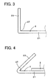
Fig. 3 is an explanatory view illustrating a down-flange step according toEmbodiment 1. -
Fig. 4 is an explanatory view illustrating a pre-hem step according to Embodiment 1. -
Fig. 5 is an explanatory view illustrating a method of forming the hem region of the aluminum alloy sheet member according toEmbodiment 1. -
Fig. 6 is an enlarged explanatory view illustrating a hem region of an aluminum alloy sheet member according to Embodiment 2. -
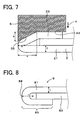
Fig. 7 is an explanatory view illustrating a method of forming the hem region of the aluminum alloy sheet member according toEmbodiment 2. -
Fig. 8 is an explanatory view illustrating a shape of a flat hem according to the prior art. - In the present invention, it is preferable to include an appressed portion at the hem end portion formed by bending the outer component by 180° in a contacting manner.
- In this case, the outer bending radius R at the hem region becomes substantially R=1.0T with respect to the sheet thickness T of the outer component so that the external appearance at the hem region can be even sharper and thus superior.
- Also, it is preferable to include no appressed portion at the hem end portion but a space which is surrounded by the outer component and the inner component and whose shape is a substantially triangular shape having a corner formed between the outer component as one of the peaks thereof.
- In this case, the external appearance at the hem region becomes even sharper so as to further improve the performance of design.
- According to the present invention, the material of the outer component is a 6000-series aluminum alloy.
- In this case, it is possible to reduce the occurrence of roughing or cracks in peripheries of the surface of the hem end portion by taking advantage of a superior bending workability of the 6000-series aluminum alloy.
- It is also possible to obtain the member suitable for use as body sheets of vehicles or the like by taking advantage of the superior strength properties of the 6000-series aluminum alloy.
- Now, a body sheet of a vehicle as the aluminum alloy sheet member according to an embodiment of the present invention will be explained by using
Figs. 1 to 5 . - As illustrated in
Figs. 1 and 2 , an aluminumalloy sheet member 1 of the present embodiment is an aluminumalloy sheet member 1 having ahem region 25 and comprising anouter component 2 which is made of an aluminum alloy sheet and aninner component 3 which is made of an aluminum alloy sheet and which is attached to theouter component 2. - At the end of the
hem portion 25, the aluminumalloy sheet member 1 has ahem end portion 255 whose outer bending radius R satisfies R=1.0T - 1.2T with respect to the sheet thickness T of theouter component 2. - A method for manufacturing the aluminum alloy sheet member will now be explained by using
Figs. 1 to 5 . - In the method for manufacturing the aluminum
alloy sheet member 1 of the present embodiment as illustrated inFigs. 3 and 4 , aflap piece 23 closer to the end than afolding base point 27 on a rear surface of theouter component 2 made of an aluminum alloy sheet is folded towards a rear surface of amain body 21 closer to the center than thefolding base point 27 around thefolding base point 27 such that an angle formed between theflap piece 23 and themain body 21 becomes an acute angle (pre-folding step). - The
inner component 3 made of an aluminum alloy sheet is then disposed on the rear surface of the outer component 2 (inner component introducing step). - Next, as illustrated in
Fig. 5 , using adie 5 which has a firstpressing surface 53 and a secondpressing surface 55 that is more projecting than the firstpressing surface 53 by the thickness of theinner component 3, pressing theflap piece 23 is performed while abutting the firstpressing surface 53 and the secondpressing surface 55 respectively against theflap piece 23 so that theinner component 3 is pinched and held between themain body 21 and theflap piece 23 through the firstpressing surface 53 and theflap piece 23 and themain body 21 are closely contacted by the secondpressing surface 55 to form an appressed portion 24 (hem region forming step). - The method of manufacturing the aluminum alloy sheet member of the present embodiment will be explained thereinafter in further details.
- First, as illustrated in
Fig. 1 , a 6000-series aluminum alloy sheet, particularly a 6016-T4 material, having a thickness of 1.0 mm was pressed to prepare anouter component 2 including aconvex portion 28 at a center thereof for use as a body sheet of a vehicle. - Another 6000-series aluminum alloy sheet same as that of the
outer component 2 was pressed to prepare aninner component 3 including a plurality of convex andconcave portions 38 for use as a body sheet of a vehicle. While a 6000-series aluminum alloy sheet was employed as the inner component in the present embodiment, it can alternatively be something different as long as it is an aluminum alloy sheet. - Next, two processing steps, namely the down-flange step and the pre-hem step were executed as the pre-folding step. More particularly, as the down-flange step as illustrated in
Fig. 3 , theflap piece 23 was folded in a substantially right-angular manner around thefolding base point 27 towards the rear surface of the main body 21 (down-flange step). Next, as the pre-hem step as illustrated inFig. 4 , a bending process was performed in which theflap piece 23 was further folded around thefolding base point 27 towards the rear surface of themain body 21 so that an angle formed between theflap piece 23 and themain body 21 becomes an acute angle (pre-hem step). - Thereafter, in the inner component introducing step as illustrated in
Fig. 4 theinner component 3 that had been preliminarily press-molded for a body sheet of a vehicle was disposed on the rear surface of theouter component 2. - Then, in the hem region forming step as illustrated in
Fig. 5 , adie 5 having a firstpressing surface 53 and a secondpressing surface 55 that is more projecting by a thickness a than the firstpressing surface 53 is prepared. The thickness a of the projecting portion of the secondpressing surface 55 of thedie 5 projecting from the firstpressing surface 53 was equal to the thickness of theinner component 3, and the thickness was thus a=1.0 mm. - By using this
die 5, the firstpressing surface 53 and the secondpressing surface 55 were respectively abutted against theflap piece 23 and pressed to press theflap piece 23 in a vertical direction (direction of arrow x inFig. 5 ). In this manner, themain body 21, theinner component 3 and theflap piece 23 are laminated in a contacting manner by the firstpressing surface 53 while theflap piece 23 and themain body 21 are laminated in a contacting manner by the secondpressing surface 55 so as to form an appressedportion 24 at thehem end portion 255. - In this manner, the aluminum
alloy sheet member 1 having thehem end portion 255 at the end of thehem region 25 whose outer bending radius R becomes R=1.0mm with respect to the sheet thickness T=1.0 mm of the outer component was manufactured as illustrated inFigs. 1 and 2 . - As illustrated in
Figs. 1 and 2 , the aluminumalloy sheet member 1 of the present embodiment comprises the appressedportion 255 at thehem end portion 255 formed by bending theouter component 2 in a contacting manner by 180°. - Accordingly, the
hem region 25 becomes a sharp shape and a superior external appearance. - The present embodiment is the embodiment in which the aluminum alloy sheet member is produced by varying the shape of the hem region of the aluminum alloy sheet member of the
Embodiment 1. - As illustrated in
Fig. 6 , the hem region of the aluminum alloy sheet member of the present embodiment has no appressed portion at thehem end portion 255 but includes a space that is surrounded by theouter component 2 and theinner component 3, and the shape of the space is a substantially triangular shape having acorner 29 formed between theouter component 2 as one of the peaks thereof. - The method for manufacturing the aluminum alloy sheet member of the present embodiment will now be explained thereinafter by using
Fig. 7 . - First, an
outer component 2 and aninner component 3 with a thickness of 1.0 mm and made of aluminum alloy sheet similar to those of the first embodiment were prepared. Then, by using theouter component 2 and theinner component 3 the pre-bending step and the inner component introducing step similar to those of the first embodiment was performed. - Then, as illustrated in
Fig. 7 , adie 6 having a firstpressing surface 63 and a taperedpressing surface 65 projecting from the first pressingsurface 63 in an oblique direction was prepared. The taperedsurface 65 of thedie 6 is arranged in that a height b from the first pressingsurface 63 satisfies b=1.5 mm and a width c satisfies c=5 mm. - By using this
die 6, the first pressingsurface 63 and the taperedpressing surface 65 were respectively abutted against theflap piece 23 and pressed to press theflap piece 23 in a vertical direction (direction of arrow y inFig. 6 ). In this manner, themain body 21, theinner component 3 and theflap piece 23 were laminated in a contacting manner by the first pressingsurface 63 while thecorner 29 formed between theouter component 2 was formed by the taperedpressing surface 65 in the space surrounded by theouter component 2 and theinner component 3. - In this manner, an aluminum
alloy sheet member 1 including no appressed portion at thehem end portion 255 but including a space which is surrounded by theouter component 2 and theinner component 3 and whose shape is a substantially triangular shape having acorner 29 formed between theouter component 2 as one of the peaks thereof was manufactured as illustrated inFig. 6 . - In the present embodiment as illustrated in
Fig. 6 , the shape of the space surrounded by theouter component 2 and theinner component 3 is a substantially triangular shape which has thecorner 29 formed by theouter component 2 as one of the peaks thereof. - Therefore, the
hem region 25 becomes a sharp shape and a superior external appearance.
Claims (3)
- An aluminum alloy sheet member (1) having a hem region (25) and comprising an outer component (2) which is made of an aluminum alloy sheet and an inner component (3) which is made of an aluminum alloy sheet and attached to the outer component (2),
wherein the aluminium alloy sheet member (1) has a hem end portion (255) at an end of the hem region (25) whose outer bending radius R satisfies R=1.0T - 1.2T with respect to a sheet thickness T of the outer component (2), characterized in that the material of the outer component (2) is a 6000-series aluminum alloy. - The aluminum alloy sheet member (1) as claimed in claim 1, wherein the aluminium alloy sheet member (1) includes an appressed portion (24) at the hem end portion (255) formed by bending the outer component (2) by 180° in a contacting manner.
- The aluminium alloy sheet member (1) as claimed in claim 1, including no appressed portion at the hem end portion (255) but a space which is surrounded by the outer component (2) and the inner component (3) and whose shape is a substantially triangular shape having a corner (29) formed between the outer component (2) as one of the peaks thereof.
Applications Claiming Priority (1)
| Application Number | Priority Date | Filing Date | Title |
|---|---|---|---|
| PCT/JP2003/011449 WO2005025771A1 (en) | 2003-09-08 | 2003-09-08 | Aluminum alloy plate member having hem portion |
Publications (3)
| Publication Number | Publication Date |
|---|---|
| EP1666171A1 EP1666171A1 (en) | 2006-06-07 |
| EP1666171A4 EP1666171A4 (en) | 2007-04-18 |
| EP1666171B1 true EP1666171B1 (en) | 2008-11-12 |
Family
ID=34308188
Family Applications (1)
| Application Number | Title | Priority Date | Filing Date |
|---|---|---|---|
| EP03818638A Expired - Lifetime EP1666171B1 (en) | 2003-09-08 | 2003-09-08 | Aluminum alloy plate member having hem portion |
Country Status (5)
| Country | Link |
|---|---|
| US (1) | US20060263623A1 (en) |
| EP (1) | EP1666171B1 (en) |
| CN (1) | CN100386164C (en) |
| DE (1) | DE60324714D1 (en) |
| WO (1) | WO2005025771A1 (en) |
Families Citing this family (3)
| Publication number | Priority date | Publication date | Assignee | Title |
|---|---|---|---|---|
| DE102007002856B4 (en) * | 2007-01-15 | 2012-02-09 | Edag Gmbh & Co. Kgaa | Device for flanging and welding or soldering of components |
| DE102014201998A1 (en) * | 2014-02-04 | 2015-08-20 | Volkswagen Aktiengesellschaft | Method for joining and embossing device |
| CN107467931A (en) * | 2016-06-08 | 2017-12-15 | 严能进 | A kind of structure of aramid aluminiumlaminates |
Family Cites Families (12)
| Publication number | Priority date | Publication date | Assignee | Title |
|---|---|---|---|---|
| CA1286208C (en) * | 1985-11-04 | 1991-07-16 | M. Elise Hyland | Aluminum alloy vehicular member |
| JPH082467B2 (en) * | 1988-08-23 | 1996-01-17 | 日産自動車株式会社 | Hemming method |
| JP3390479B2 (en) * | 1993-03-03 | 2003-03-24 | 本田技研工業株式会社 | Hemming equipment |
| DE19840617B4 (en) * | 1998-09-05 | 2006-08-31 | Daimlerchrysler Ag | Folding connection between an outer panel and an inner panel and method for producing a rabbet joint |
| JP2000160274A (en) * | 1998-11-26 | 2000-06-13 | Kobe Steel Ltd | Aluminum alloy sheet excellent in resistance to rupture at bending, and method of its bending |
| US6425277B2 (en) * | 1999-12-30 | 2002-07-30 | Unova Ip Corp. | Sheet metal hemming method and apparatus |
| US6257043B1 (en) * | 1999-12-30 | 2001-07-10 | Unova Ip Corp. | Modified flat hem apparatus and method |
| US20040094249A1 (en) * | 2001-03-28 | 2004-05-20 | Hidetoshi Uchida | Aluminum alloy sheet excellent in formability and hardenability during baking of coating and method for production thereof |
| JP4253140B2 (en) * | 2001-07-25 | 2009-04-08 | 株式会社神戸製鋼所 | Hemming method of aluminum alloy panel material and aluminum alloy panel material |
| JP3775311B2 (en) * | 2001-10-01 | 2006-05-17 | 日産自動車株式会社 | Hemming method |
| US6672121B2 (en) * | 2002-04-15 | 2004-01-06 | General Motors Corporation | Flat pinch hemming of aluminum panels |
| US6739169B2 (en) * | 2002-04-26 | 2004-05-25 | Valiant Corporation | Method for hemming |
-
2003
- 2003-09-08 EP EP03818638A patent/EP1666171B1/en not_active Expired - Lifetime
- 2003-09-08 WO PCT/JP2003/011449 patent/WO2005025771A1/en not_active Ceased
- 2003-09-08 CN CNB038270048A patent/CN100386164C/en not_active Expired - Lifetime
- 2003-09-08 US US10/570,614 patent/US20060263623A1/en not_active Abandoned
- 2003-09-08 DE DE60324714T patent/DE60324714D1/en not_active Expired - Lifetime
Also Published As
| Publication number | Publication date |
|---|---|
| WO2005025771A1 (en) | 2005-03-24 |
| EP1666171A4 (en) | 2007-04-18 |
| CN1826190A (en) | 2006-08-30 |
| CN100386164C (en) | 2008-05-07 |
| EP1666171A1 (en) | 2006-06-07 |
| US20060263623A1 (en) | 2006-11-23 |
| DE60324714D1 (en) | 2008-12-24 |
Similar Documents
| Publication | Publication Date | Title |
|---|---|---|
| US6928848B2 (en) | Flanging processes with radial compression of the blank stretched surface | |
| CN101011929B (en) | Panel fastening method and panel part for automobile | |
| US6257043B1 (en) | Modified flat hem apparatus and method | |
| US8042372B2 (en) | Method of making an automotive closure panel assembly | |
| US20110156444A1 (en) | Panel structure and manufacturing method thereof | |
| US6907763B2 (en) | Method for hemming | |
| US20070186608A1 (en) | Sheet Metal Hem Forming Process | |
| CN105531049B (en) | Press-formed article, method for producing press-formed article, and apparatus for producing press-formed article | |
| CN104275374B (en) | Panel assembly and method of forming same | |
| CN113226584B (en) | Press forming method | |
| EP1666171A1 (en) | Aluminum alloy plate member having hem portion | |
| JP2004098154A (en) | Method for forming hem of aluminum alloy panel, and aluminum alloy panel | |
| US11376650B2 (en) | Method for producing trim strips and trim strips produced using said method | |
| JP3857744B2 (en) | Hemming method for plate material and jig for hemming | |
| JP2004042061A (en) | Aluminum alloy plate member having a hem portion | |
| CN113879407A (en) | Patch board engine cover inner board, automobile and manufacturing method | |
| US20250289050A1 (en) | Metal forming process for automotive panels | |
| EP4541474A1 (en) | Method for producing panel structure | |
| EP0995514B1 (en) | Panel assembly of hemmed panels and its method of manufacture | |
| US20220258224A1 (en) | Flange forming device and method of forming a flange on a sheet metal part to reduce surface distortion | |
| JP2005161389A (en) | Method for flat hemming aluminum alloy panel | |
| RU2323057C2 (en) | Bending method by right angle with small radius | |
| JPH06106266A (en) | Production of double walled structure | |
| RU43840U1 (en) | VEHICLE HOOD | |
| JP2002022631A (en) | Method for evaluating hemming properties of aluminum alloy panel material |
Legal Events
| Date | Code | Title | Description |
|---|---|---|---|
| PUAI | Public reference made under article 153(3) epc to a published international application that has entered the european phase |
Free format text: ORIGINAL CODE: 0009012 |
|
| 17P | Request for examination filed |
Effective date: 20060227 |
|
| AK | Designated contracting states |
Kind code of ref document: A1 Designated state(s): DE FR |
|
| RIN1 | Information on inventor provided before grant (corrected) |
Inventor name: UCHIDA, HIDETOSHI |
|
| DAX | Request for extension of the european patent (deleted) | ||
| RBV | Designated contracting states (corrected) |
Designated state(s): DE FR |
|
| A4 | Supplementary search report drawn up and despatched |
Effective date: 20070319 |
|
| RIC1 | Information provided on ipc code assigned before grant |
Ipc: B21D 39/02 20060101AFI20050331BHEP |
|
| 17Q | First examination report despatched |
Effective date: 20070619 |
|
| GRAP | Despatch of communication of intention to grant a patent |
Free format text: ORIGINAL CODE: EPIDOSNIGR1 |
|
| GRAS | Grant fee paid |
Free format text: ORIGINAL CODE: EPIDOSNIGR3 |
|
| RIN1 | Information on inventor provided before grant (corrected) |
Inventor name: UCHIDA, HIDETOSHIC/O SUMITOMO LIGHT METAL INDUSTRI |
|
| GRAA | (expected) grant |
Free format text: ORIGINAL CODE: 0009210 |
|
| AK | Designated contracting states |
Kind code of ref document: B1 Designated state(s): DE FR |
|
| REF | Corresponds to: |
Ref document number: 60324714 Country of ref document: DE Date of ref document: 20081224 Kind code of ref document: P |
|
| PLBE | No opposition filed within time limit |
Free format text: ORIGINAL CODE: 0009261 |
|
| STAA | Information on the status of an ep patent application or granted ep patent |
Free format text: STATUS: NO OPPOSITION FILED WITHIN TIME LIMIT |
|
| 26N | No opposition filed |
Effective date: 20090813 |
|
| REG | Reference to a national code |
Ref country code: FR Ref legal event code: PLFP Year of fee payment: 14 |
|
| REG | Reference to a national code |
Ref country code: FR Ref legal event code: PLFP Year of fee payment: 15 |
|
| REG | Reference to a national code |
Ref country code: FR Ref legal event code: PLFP Year of fee payment: 16 |
|
| PGFP | Annual fee paid to national office [announced via postgrant information from national office to epo] |
Ref country code: DE Payment date: 20220803 Year of fee payment: 20 |
|
| PGFP | Annual fee paid to national office [announced via postgrant information from national office to epo] |
Ref country code: FR Payment date: 20220808 Year of fee payment: 20 |
|
| REG | Reference to a national code |
Ref country code: DE Ref legal event code: R071 Ref document number: 60324714 Country of ref document: DE |
|
| P01 | Opt-out of the competence of the unified patent court (upc) registered |
Effective date: 20230816 |