EP1665740B1 - Connection system, base part and adapter part for connecting mobile radio terminals - Google Patents
Connection system, base part and adapter part for connecting mobile radio terminals Download PDFInfo
- Publication number
- EP1665740B1 EP1665740B1 EP04786721A EP04786721A EP1665740B1 EP 1665740 B1 EP1665740 B1 EP 1665740B1 EP 04786721 A EP04786721 A EP 04786721A EP 04786721 A EP04786721 A EP 04786721A EP 1665740 B1 EP1665740 B1 EP 1665740B1
- Authority
- EP
- European Patent Office
- Prior art keywords
- interface
- protocol
- connection system
- mechanical
- electronics
- Prior art date
- Legal status (The legal status is an assumption and is not a legal conclusion. Google has not performed a legal analysis and makes no representation as to the accuracy of the status listed.)
- Not-in-force
Links
Images


Classifications
-
- H—ELECTRICITY
- H04—ELECTRIC COMMUNICATION TECHNIQUE
- H04M—TELEPHONIC COMMUNICATION
- H04M1/00—Substation equipment, e.g. for use by subscribers
- H04M1/60—Substation equipment, e.g. for use by subscribers including speech amplifiers
- H04M1/6033—Substation equipment, e.g. for use by subscribers including speech amplifiers for providing handsfree use or a loudspeaker mode in telephone sets
- H04M1/6041—Portable telephones adapted for handsfree use
- H04M1/6075—Portable telephones adapted for handsfree use adapted for handsfree use in a vehicle
-
- H—ELECTRICITY
- H04—ELECTRIC COMMUNICATION TECHNIQUE
- H04B—TRANSMISSION
- H04B1/00—Details of transmission systems, not covered by a single one of groups H04B3/00 - H04B13/00; Details of transmission systems not characterised by the medium used for transmission
- H04B1/38—Transceivers, i.e. devices in which transmitter and receiver form a structural unit and in which at least one part is used for functions of transmitting and receiving
- H04B1/3827—Portable transceivers
- H04B1/3877—Arrangements for enabling portable transceivers to be used in a fixed position, e.g. cradles or boosters
-
- H—ELECTRICITY
- H04—ELECTRIC COMMUNICATION TECHNIQUE
- H04M—TELEPHONIC COMMUNICATION
- H04M1/00—Substation equipment, e.g. for use by subscribers
- H04M1/60—Substation equipment, e.g. for use by subscribers including speech amplifiers
- H04M1/6033—Substation equipment, e.g. for use by subscribers including speech amplifiers for providing handsfree use or a loudspeaker mode in telephone sets
- H04M1/6041—Portable telephones adapted for handsfree use
- H04M1/6075—Portable telephones adapted for handsfree use adapted for handsfree use in a vehicle
- H04M1/6083—Portable telephones adapted for handsfree use adapted for handsfree use in a vehicle by interfacing with the vehicle audio system
- H04M1/6091—Portable telephones adapted for handsfree use adapted for handsfree use in a vehicle by interfacing with the vehicle audio system including a wireless interface
-
- H—ELECTRICITY
- H04—ELECTRIC COMMUNICATION TECHNIQUE
- H04M—TELEPHONIC COMMUNICATION
- H04M2250/00—Details of telephonic subscriber devices
- H04M2250/02—Details of telephonic subscriber devices including a Bluetooth interface
Definitions
- the invention relates to a connection system for connecting mobile radio terminals with a vehicle arranged in an electronics according to the preamble of patent claim 1.
- EP 1 119 160 A2 For example, a universal connection system for mobile terminals is described.
- a hands-free device that can be installed in a vehicle is formed by a universal, fixed system part and a replaceable system part.
- the universal system part has a power supply device, a microphone and a speaker, which are electrically connected to the power supply device, and a special cable.
- the cable has a first electrical connection element for connection to the power supply device and a second connection element for connection to the vehicle antenna.
- the cable is further connected to a holding plate, which is connectable to the replaceable system part.
- the replaceable system part here consists of a holding part, which serves to accommodate the mobile terminal and having an electronics for adjusting the power supply between power supply device and mobile terminal.
- connection system which serves the connection of mobile radio terminals with an arranged in a vehicle electronics
- the connection system is a base for permanent Attachment in the vehicle, an adapter part and one or more holding parts for receiving a respective mobile terminal, which are connectable via a second mechanical and electrical interface with the base, the second mechanical and electrical interface of the base an interface for connecting holding parts for mobile devices which has a control device for communication via the second interface by means of a first, universal protocol and for converting the first, universal protocol into a second, terminal-specific protocol
- the adapter part has a mechanical and electrical interface for the electrical and mechanical connection to the base part of the connection system having.
- the invention is based on the object to improve the flexibility of a connection system that serves the connection of mobile terminals with an arranged in a vehicle electronics.
- connection system for the connection of mobile radio terminals with an arranged in a vehicle electronics, which has in addition to the features specified in the preamble of the characterizing part of claim 1.
- the invention achieves a number of advantages.
- the electronics permanently installed in the vehicle can be connected with various types of mobile radio terminals with little effort. It is thus possible to connect mobile radio terminals provided with a Bluetooth interface and mobile radio terminals provided with different proprietary galvanic control interfaces to one and the same vehicle-side electronics without having to make any changes in this electronics.
- cost advantages in production are achieved and the user-friendliness of the connection system is increased.
- the mechanical and electrical interface of the basic part may be an interface for communication by means of one or more terminal-specific protocols.
- the communication device is then preferably designed such that it transmits to the electronics or signal processing device data that the signal processing device causes and / or allows the signal processing device to communicate with the communication device by means of the first protocol.
- the base part has a selection circuit for selectively connecting an electrical interface and the mechanical and electrical interface or the electrical interface with the communication device.
- the switching can be done here automatically or manually controlled.
- the selection circuit ensures that the vehicle-mounted electronics are always connected to the desired mobile radio terminal.
- the electrical interface represents an interface for communication by means of the first, universal protocol.
- the base can be made particularly simple and inexpensive.
- the communication device consists of several, on a separate electrical connection element, such as a circuit board, arranged electrical components, wherein the separate board is connected via a plurality of contact elements with the motherboard of the base.
- the communication device has the form of a "stamp", which can be easily applied to a board of the basic part, the signal processing device or the adapter part to expand the scope of performance.
- This is a particularly cost-effective retrofitting of a connection system with the additional achieved by the invention Feature possible.
- an adapter part of the connection system further advantages can be achieved in that the communication device determines whether the vehicle-side electronics communicates via the mechanical and electrical interface with the first protocol and, if this is not the case, transmits data that the vehicle-side Electronics causes and / or allows the vehicle electronics to communicate with the communication device by means of the first protocol.
- the adapter part can be used both in connection systems in which the holding parts have a control device for converting the first, universal protocol into a second, vehicle-specific protocol, and can be used in connection systems in which the holding part or an upstream signal processing device due to predetermined or Data downloaded from the holding part is already communicated with the holding part via a corresponding terminal-specific protocol.
- the adapter part is therefore flexible for a variety of different Kunststoffsyteme used.
- the adapter part has a housing which forms the shape of a cover which covers the electrical and mechanical interface. This results in a double usage:
- an optical and mechanical coverage of the interface in the event that this is not needed, and on the other hand increased flexibility through the possibility of communication with another group of mobile terminals.
- This mobile terminals can remain here, for example, in the pocket of the participant or in the trunk of the vehicle.
- one or more input and output means on the adapter part and thus emulate the user interface of the mobile terminal. This allows the usual operation of the mobile terminal, although the mobile terminal is not in the visual or tactile of the subscriber.
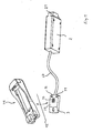
- Fig. 1 shows several components of a dacassytems 1 for connecting a mobile terminal with a vehicle.
- Fig. 1 shows a holding part 41, a base 3 and a signal processing device or electronics. 2
- connection system 1 is to facilitate the understanding of the invention and, as shown in the Fig. 4 to 7 described to be developed to the invention.
- the holding part 41 serves to accommodate a specific type of mobile radio terminals.
- the holding part 41 On the front side, the holding part 41 has a recess which is formed according to the outer shape of this mobile terminal type and which, possibly together with corresponding holding, fixing or locking means, a mechanical fixation of mobile terminals of this type in the holding part 41 allows.
- the holding part 41 also includes electrical contact means that allow an electrical connection between the mobile terminal and the holding part 41.
- the holding part 41 for example, an electrical connector element, which in a corresponding socket of the mobile device En convinceds engages with the introduction of the mobile terminal in the holding part 41.
- the holding part not only has an electrical connector element, but also two or more such connector elements, for example, a first connector element of the connection of the mobile terminal with an external vehicle antenna and a second connector element with the galvanic connection a control interface and / or a power supply interface provides.
- Both the mechanical interface, which allows a mechanical fixation of the mobile terminal, and the electrical interface, which allows an electrical connection between the holding part and the mobile terminal are in this case designed according to the respective mobile terminal type.
- connection system has more, in Fig. 1 not shown, holding parts, which are intended for other types of mobile terminal equipment and therefore implement a different mechanical and / or electrical interface.
- the holding part 41 has an electrical and mechanical interface 12, which serves the electrical and mechanical connection of the holding part 41 with the base part 3. It thus has, for example, an electrical contact element which is arranged as a counterpart to an electrical contact element 33 of the base part 3 in the holding part 41 and in the mechanical fixing of the holding part 41 on the base part 3 with the contact element 33 to form an electrical connection between holding part 41st and base 3 cooperates.
- the electrical and mechanical Interface 12 is in this case identical in all holding parts of the connection system, so that each of these holding parts is electrically and mechanically connected to the thus universal base part 3.
- the holding part 41 or the base part 3 in this case preferably have a locking mechanism, which allows a firm fixation of the holding part 41 on the base part 3.
- the holding part 41 is also possible for the holding part 41 to be connectable to the base part 3 via a cable provided with a plug element.
- the base 3 is permanently mounted in the vehicle, preferably in the tactile or visual range of the driver.
- the base 3 consists of a housing 34 which has recesses for the electrical contact element 33 and electrical switches 31 and 32. Furthermore, the base part 3 has an electronic circuit and the electrical contact element 33 connected to the electronic circuit.
- the housing 34 can be fastened permanently in the vehicle so that the base plate 34 has recesses for screwing or latching the base part to the vehicle, for example.
- the switches 31 and 32 serve to control functions performed by the electronics of the base 3, the signal processing device 2, the holding part 41 and / or the mobile radio terminal.
- the base 3 is connected to the signal processing device 2 via a cable 20.
- the signal processing device 2 is also permanently installed in the vehicle and consists of a housing and an electronics arranged in this housing. This electronics preferably performs the function of a hands-free device. However, it is also possible that this electronics provides only partial functions of a hands-free device. Furthermore, it is also possible that the signal processing device provides functions such as voice processing, voice recognition and / or vehicle navigation.
- the signal processing device 2 further comprises an electrical connection element 21, which serves for example for the connection of microphones or loudspeakers permanently installed in the vehicle, the connection to a communication bus installed in the vehicle or the connection of other electronic devices of the vehicle.
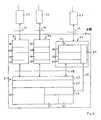
- Fig. 2 shows the connection system 1 and mobile terminals 51, 52 and 53.
- the connection system 1 comprises the signal processing means 2, the base part 3 and a plurality of different holding parts, of which in Fig. 2 the holding part 41 and a holding part 42 are shown.
- the signal processing device 2 is connected to the base part via an electrical interface 11, the base part 3 is connected to the holding parts 41 and 42 via the mechanical and electrical interface 12 and the holding parts 41 and 42 are via respective terminal-specific interfaces 15 and 14th connected to the mobile terminals 51 and 52.
- the signal processing device 2 and the holding parts 41 and 42 each have a microprocessor or microcontroller, which performs functions in the context of the communication between the signal processing device 2 and the mobile radio terminals 51 and 52.
- the signal processing device 2 has two communication units 27 and 26 and a control unit 22.
- the holding parts 41 and 42 have, from a functional point of view, communication units 44, 46, 48 and 49 as well as control devices 45 and 47.
- the functions of these communication units are provided by the expiration of a respective program code on the respective microprocessor or microcontroller in cooperation with associated peripheral components.
- the control unit 22 is formed by functions of the signal processing device 2, which communicate with the mobile radio terminals 51 or 52 to perform their function. Such a function is, for example, a hands-free device with integrated voice recognition. For communication with the terminal 51 or 52, the control unit 22 accesses the communication unit 26, which in turn accesses the communication unit 27.
- the communication unit 27 provides functions that allow the exchange of data via the electrical interface 11 by means of a transport protocol.
- the communication unit 26 provides functions that enable communication via the electrical interface 11 by means of a universal communication protocol based on this transport protocol.
- the communication units 44 and 49 of the holding parts 41 and 42 include the functions of the communication units 27 and 26, respectively, so that communication between the control unit 22 and the controllers 45 and 47 is possible by means of the universal protocol.
- the communication units 46 and 48 provide functions that enable communication with the terminals 51 and 52, respectively, via a respective terminal-specific protocol.
- the controllers 45 and 47 provide protocol conversion between the respective terminal-specific protocol and the universal protocol.
- the base part 3 has, from a functional point of view, a selection circuit 35 and a communication device 5.
- the communication device 5 is preferably formed by a microcontroller or microprocessor with associated peripheral elements.
- the communication device 5 here has three communication units 510, 520 and 530 as well a control unit 54.
- the communication units 510 and 520 perform the function of the communication units 27 and 26, respectively, and thus allow communication between the control unit 22 and the communication unit 530 via the universal protocol.
- the communication unit 530 provides functions that enable wireless communication over another interface 13 with the mobile terminal 53.
- the further interface 13 is a radio interface.
- the communication is based on ultrasound or infrared.
- the communication takes place via the further interface 13, preferably by means of the Bluetooth protocol, so that the communication unit 530 performs a conversion between the universal protocol and the Bluetooth protocol.
- the control unit 54 represents an optimal extension of the communication device 5.
- the control unit 54 checks whether the signal processing device 2 communicates via the electrical interface 11 by means of the universal protocol. If this is not the case, it transmits to the signal processing device 2 data 56, which leave the signal processing device 2 and / or enable the signal processing device 2, with the communication device 5 via the electrical interface 11 by means of the universal Protocol to communicate. This makes it possible that the base part 3 can be used in various connection systems with differently designed holding parts and signal processing facilities.
- the signal processing device 2 communicates with the mobile radio terminals 51 and 52 not by means of the universal protocol, but already in each case by means of the respective terminal-specific protocol.
- different protocols for the communication via the electrical interface 11 are used by the signal processing device 2, depending on which terminal and which holding part is connected to the base part 3.
- the selection of the respective correct protocol takes place, for example, by means of data which are sent from the holding parts 41 or 42 to a control unit 25 of the signal processing device 2.
- control unit 54 transmits according to a first further embodiment, a command to a control unit 25 of the signal processing device 2, which refers to a specific, in the signal processing device 2 awaiting protocol.
- this protocol is used by the signal processing device 2 for communication via the electrical interface 11.
- control unit 54 transmits to the control unit 25 software and data which first enable the signal processing device 2 to communicate via the electrical interface 11 by means of the protocol expected from the communication device 5.
- Fig. 2 shows for this purpose two control units 23 and 24, wherein the control unit 23, the signal processing-side functions for the execution of the first further embodiment and the control unit 24, the signal processing-side functions for the execution of the second further embodiment.
- the selection circuit 35 is used for the selective connection of the electrical interface 11 with the mechanical and electrical interface 12 or the electrical interface 11 with the communication device 5.
- the switching can in this case due to the manual operation of a arranged in the base 3 switch or automatically respectively.
- the base part 3 has a contact switch which detects whether a holding part is fixed on the base part 3. If this is the case, the electrical interface 11 is connected to the mechanical and electrical interface 12. If this is not the case, then the electrical interface 11 is connected to the communication device 5.
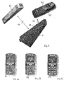
- Fig. 3 now shows a further embodiment of the base part. 3
- the base part 3 here has a housing upper part 341 and a housing lower part 342.
- a circuit board 36 is arranged, which is electrically connected to the connection cable 20.
- the board 36 is hereby prepared for receiving the communication device 5.
- several electrical contact points are provided here, on which the communication device 5 can be placed.
- the communication device 5 consists of an electrical connection element 57, on which a plurality of components 58 and 59 are applied.
- the electrical connection element 57 is preferably a multilayer circuit board which is provided on one side with electrical contact points for electrical connection to the circuit board 36.
- the base part 3 can therefore be equipped in a simple manner with the communication device 5 or not equipped.
- Fig. 4 illustrates the operation of a connection system 110 according to the invention, which serves for the connection of mobile radio terminals 51, 52 and 53 with an arranged in the vehicle electronics 2.
- Fig. 4 shows the connection system 110, the holding parts 41 and 42 and an adapter part 43.
- a base is arranged (not in Fig. 4 shown), which has on both sides of the mechanical and electrical interface 12 and thus the signals between the signal processing device 2 and holding part 41, holding part 42 and adapter part 43 looped through.
- the adapter part 43 has the same electrical and mechanical interface 12 as the holding parts 41 and 42, so that the adapter part 43 in the same manner as the holding parts 41 and 42 is connectable to the base part. Next, the adapter part 43 on the communication device 5.
- the signal processing device 2 the holding parts 41 and 42 and the mobile radio terminals 51, 52 and 53 are as here Fig. 1 and Fig. 2 designed.
- the base is like the base 3 after Fig. 1 and Fig. 2 designed, with the difference that the basic part does not have the communication device 5 and not the selection circuit 35.
- part or all of the functions of the signal processing device 2 may be shifted from the signal processing device 2 into the basic part.
- Fig. 5 shows a preferred embodiment of the adapter part 43 and the base 6 used for the connection system 110th
- Fig. 5 shows a base 6, which is connectable via the electrical and mechanical interface 12 with the adapter part 43 or the holding part 42 with inserted mobile terminal 52.
- the adapter part 43 has the form of a cover, which covers the mechanical and electrical interface 12 of the base 6 here.
- the lower part of the housing of the adapter part 43 therefore has recesses which are latched to the in Fig. 5 allows raster elements shown.
- the lower part of the housing has an electrical contact element which, as a counterpart to the in Fig. 5 shown contact element 33 of the base 6 is arranged.
- the adapter part 43 has a housing with a housing shape, which is the base surface of the base part 6 positively covers and thus the mechanical and electrical interface 12 completely disappear visually. Furthermore, the adapter part can also have one or more light-emitting diodes for status display.
- Fig. 6a, Fig. 6b and Fig. 6c show further possible embodiments of an adapter part for use in the connection system 110.
- An adapter part 73 has a plurality of input and output means, which simulate the user interface of the mobile terminal 53, so that the complete scope of this mobile terminal is available to the user, without this in the touch area and / or field of vision of the driver must be arranged.
- An adapter part 72 has a reduced user interface, which essentially comprises a display device and keys for changing the volume, temporarily interrupting the communication connection and aborting / initiating the communication connection.
- Fig. 7 shows the adapter part 73 with an electrical connection element 82, a connection socket for a cable 81, an EEPROM 83, a power supply device 84, a driver 85 for the signaling lines, an adapter circuit 86 for adapting the audio signals, a microcontroller 87 and an input and output unit 88, which includes a display 884, a keypad 883, an LED 882, and operation switches 881.
- the microcontroller 87 is further connected to an RF circuit, which in turn is provided with an antenna for communication via the radio interface 13.
- the microcontroller 87 in this case provides the functions of the communication device 5, as this example in Fig. 2 and Fig. 4 are described.
Abstract
Description
Die Erfindung betrifft ein Verbindungssystem zur Verbindung von Mobilfunk-Endgeräten mit einer in einem Fahrzeug angeordneten Elektronik nach dem Oberbegriff des Patentanspruchs 1.The invention relates to a connection system for connecting mobile radio terminals with a vehicle arranged in an electronics according to the preamble of patent claim 1.
In
Eine Freisprech-Einrichtung, die in einem Fahrzeug installiert werden kann, wird von einem universellen, festen Systemteil und einem austauschbaren Systemteil gebildet. Der universelle Systemteil weist eine Stromversorgungs-Einrichtung, ein Mikrofon und einen Lautsprecher, die elektrisch mit der Stromversorgungs-Einrichtung verbunden sind, und ein spezielles Kabel auf. Das Kabel weist ein erstes elektrisches Verbindungselement zur Verbindung mit der Stromversorgungs-Einrichtung und ein zweites Verbindungselement zur Verbindung mit der Fahrzeug-Antenne auf. Das Kabel ist weiter mit einer Halteplatte verbunden, die mit dem austauschbaren Systemteil verbindbar ist. Der austauschbare Systemteil besteht hierbei aus einem Halteteil, das der Aufnahme des Mobilfunk-Endgerätes dient und das eine Elektronik zur Anpassung der Stromversorgung zwischen Stromversorgungs-Einrichtung und Mobilfunk-Endgerät aufweist.A hands-free device that can be installed in a vehicle is formed by a universal, fixed system part and a replaceable system part. The universal system part has a power supply device, a microphone and a speaker, which are electrically connected to the power supply device, and a special cable. The cable has a first electrical connection element for connection to the power supply device and a second connection element for connection to the vehicle antenna. The cable is further connected to a holding plate, which is connectable to the replaceable system part. The replaceable system part here consists of a holding part, which serves to accommodate the mobile terminal and having an electronics for adjusting the power supply between power supply device and mobile terminal.
Aus der
Der Erfindung liegt nun die Aufgabe zugrunde, die Flexibilität eines Verbindungssystems, das der Verbindung von Mobilfunk-Endgeräten mit einer in einem Fahrzeug angeordneten Elektronik dient, zu verbessern.The invention is based on the object to improve the flexibility of a connection system that serves the connection of mobile terminals with an arranged in a vehicle electronics.
Diese Aufgabe wird von einem Verbindungssystem zur Verbindung von Mobilfunk-Endgeräten mit einer in einem Fahrzeug angeordneten Elektronik gelöst, das außer den im Oberbegriff auch die im kennzeichnenden Teil des Patentanspruchs 1 angegebenen Merkmale aufweist.This object is achieved by a connection system for the connection of mobile radio terminals with an arranged in a vehicle electronics, which has in addition to the features specified in the preamble of the characterizing part of claim 1.
Durch die Erfindung werden eine Vielzahl von Vorteilen erzielt. So wird beispielsweise ermöglicht, dass die fest im Fahrzeug installierte Elektronik mit geringem Aufwand mit verschiedenartigen Mobilfunk-Endgeräten verbindbar ist. So ist es möglich, mit einer Bluetooth-Schnittstelle versehene Mobilfunk-Endgeräte und mit unterschiedlichen proprietären, galvanischen Steuerschnittstellen versehene Mobilfunk-Endgeräte mit ein und derselben fahrzeugseitigen Elektronik zu verbinden, ohne Änderungen in dieser Elektronik vornehmen zu müssen. Weiter werden Kostenvorteile in der Produktion erzielt und die Benutzerfreundlichkeit des Verbindungssystems erhöht.The invention achieves a number of advantages. Thus, for example, it is made possible that the electronics permanently installed in the vehicle can be connected with various types of mobile radio terminals with little effort. It is thus possible to connect mobile radio terminals provided with a Bluetooth interface and mobile radio terminals provided with different proprietary galvanic control interfaces to one and the same vehicle-side electronics without having to make any changes in this electronics. Furthermore, cost advantages in production are achieved and the user-friendliness of the connection system is increased.
Vorteilhafte Ausgestaltungen der Erfindung sind in den Unteransprüchen bezeichnet.Advantageous embodiments of the invention are designated in the subclaims.
So ist es beispielsweise möglich, ein Grundteil mit einer mechanischen und elektrischen Schnittstelle auszugestalten, die für den Anschluß von Halteteilen für Mobilfunk-Endgeräte geeignet ist, die eine Steuereinrichtung zur Konvertierung des ersten, universellen Protokolls in ein zweites, endgerätespezifisches Protokoll aufweisen. Durch diese Maßnahme wird die Aufwärts-Kompatibilität des Verbindungssystems sichergestellt und ermöglicht, das Verbindungssystem für beliebige weitere, zukünftige Mobilfunk-Endgeräte auszulegen.Thus, it is possible, for example, to design a basic part with a mechanical and electrical interface which is suitable for the connection of holding parts for mobile radio terminals, which have a control device for converting the first, universal protocol into a second, terminal-specific protocol. This measure ensures the upward compatibility of the interconnect system and allows the interconnect system to be designed for any future mobile handset.
Weiter ist es auch möglich, dass die mechanische und elektrische Schnittstelle des Grundteils eine Schnittstelle zur Kommunikation mittels eines oder mehreren endgeräte-spezifischen Protokollen ist. Die Kommunikations-Einrichtung ist dann vorzugsweise so ausgestaltet, dass sie an die Elektronik bzw. Signalvearbeitungs-Einrichtung Daten übermittelt, die die Signalverarbeitungs-Einrichtung veranlasst und/oder es der Signalverarbeitungs-Einrichtung ermöglicht, mit der Kommunikations-Einrichtung mittels des ersten Protokolls zu kommunizieren.Furthermore, it is also possible for the mechanical and electrical interface of the basic part to be an interface for communication by means of one or more terminal-specific protocols. The communication device is then preferably designed such that it transmits to the electronics or signal processing device data that the signal processing device causes and / or allows the signal processing device to communicate with the communication device by means of the first protocol.
Weitere Vorteile werden dadurch erzielt, dass das Grundteil eine Auswahl-Schaltung zur wahlweisen Verbindung einer elektrischen Schnittstelle und der mechanischen und elektrischen Schnittstelle oder der elektrischen Schnittstelle mit der Kommunikations-Einrichtung aufweist. Die Umschaltung kann hierbei automatisch oder manuell gesteuert erfolgen. Durch die Auswahl-Schaltung wird sichergestellt, dass die fahrzeugseitige Elektronik stets mit dem gewünschten Mobilfunk-Endgerät verbunden ist.Further advantages are achieved in that the base part has a selection circuit for selectively connecting an electrical interface and the mechanical and electrical interface or the electrical interface with the communication device. The switching can be done here automatically or manually controlled. The selection circuit ensures that the vehicle-mounted electronics are always connected to the desired mobile radio terminal.
Es ist zweckmäßig, dass die elektrische Schnittstelle eine Schnittstelle zur Kommunikation mittels des ersten, universellen Protokolls darstellt. In diesem Fall kann das Grundteil besonders einfach und kostengünstig ausgestaltet werden.It is expedient that the electrical interface represents an interface for communication by means of the first, universal protocol. In this case, the base can be made particularly simple and inexpensive.
Produktionstechnische Vorteile lassen sich dadurch erzielen, dass die Kommunikations-Einrichtung aus mehreren, auf einem separaten elektrischen Verbindungselement, beispielsweise einer Platine, angeordneten elektrischen Bauteilen besteht, wobei die separate Platine über mehrere Kontaktelemente mit der Hauptplatine des Grundteils verbunden ist. Die Kommunikations-Einrichtung hat demnach die Form einer "Briefmarke", die zur Erweiterung des Leistungsumfangs auf einfache Weise auf eine Platine des Grundteils, der Signalverarbeitungs-Einrichtung oder des Adapterteils aufbringbar ist. Hierdurch ist eine besonders kostengünstige Nachrüstung eines Verbindungssystems mit dem durch die Erfindung erzielten zusätzlichen Leistungsmerkmal möglich. Auch ergeben sich Kostenvorteile in der Erstausstattung, da für den erhöhten Leistungsumfang nur die "Briefmarke" auf die dafür vorgesehene Stelle der Platine des Grundteils, der Signalverarbeitungs-Einrichtung oder des Halteteils aufgebracht werden muss.Production advantages can be achieved in that the communication device consists of several, on a separate electrical connection element, such as a circuit board, arranged electrical components, wherein the separate board is connected via a plurality of contact elements with the motherboard of the base. Accordingly, the communication device has the form of a "stamp", which can be easily applied to a board of the basic part, the signal processing device or the adapter part to expand the scope of performance. This is a particularly cost-effective retrofitting of a connection system with the additional achieved by the invention Feature possible. There are also cost advantages in the initial equipment, since only the "stamp" must be applied to the space provided for the board of the base, the signal processing device or the holding part for the increased scope of service.
Bei einem Adapterteil des erfindungsgemäßen Verbindungssystems lassen sich weitere Vorteile dadurch erzielen, dass die Kommunikations-Einrichtung ermittelt, ob die fahrzeugseitige Elektronik über die mechanische und elektrische Schnittstelle mit dem ersten Protokoll kommuniziert und, falls dies nicht der Fall ist, Daten übermittelt, die die fahrzeugseitige Elektronik veranlasst und/oder es der fahrzeugseitigen Elektronik ermöglicht, mit der Kommunikations-Einrichtung mittels des ersten Protokolls zu kommunizieren. Dadurch ist das Adapterteil sowohl in Verbindungssystemen einsetzbar, bei denen die Halteteile eine Steuereinrichtung zur Konvertierung des ersten, universellen Protokolls in ein zweites, fahrzeugspezifisches Protokoll verfügen, als auch in Verbindungssysteme einsetzbar, in denen das Halteteil oder eine vorgelagerte Signalverarbeitungs-Einrichtung aufgrund von vorgegebenen oder von dem Halteteil heruntergeladenen Daten mit dem Halteteil bereits über ein entsprechendes endgerätespezifisches Protokoll kommuniziert. Das Adapterteil ist demnach flexibel für eine Vielzahl unterschiedlicher Verbindungssyteme einsetzbar.In an adapter part of the connection system according to the invention further advantages can be achieved in that the communication device determines whether the vehicle-side electronics communicates via the mechanical and electrical interface with the first protocol and, if this is not the case, transmits data that the vehicle-side Electronics causes and / or allows the vehicle electronics to communicate with the communication device by means of the first protocol. As a result, the adapter part can be used both in connection systems in which the holding parts have a control device for converting the first, universal protocol into a second, vehicle-specific protocol, and can be used in connection systems in which the holding part or an upstream signal processing device due to predetermined or Data downloaded from the holding part is already communicated with the holding part via a corresponding terminal-specific protocol. The adapter part is therefore flexible for a variety of different Verbindungssyteme used.
Besonders vorteilhaft ist es hierbei, dass das Adapterteil ein Gehäuse besitzt, das die Form einer Abdeckung ausformt, welche die elektrische und mechanische Schnittstelle abdeckt. Hierdurch ergibt sich eine Doppel-Nutzung:It is particularly advantageous in this case that the adapter part has a housing which forms the shape of a cover which covers the electrical and mechanical interface. This results in a double usage:
Zum einen eine optische und mechanische Abdeckung der Schnittstelle, für den Fall, dass diese nicht benötigt wird, und zum anderen eine erhöhte Flexibilität durch die Möglichkeit der Kommunikation mit einer weiteren Gruppe von Mobilfunk-Endgeräten. Diese Mobilfunk-Endgeräte können hierbei beispielsweise in der Tasche des Teilnehmers oder im Kofferraum des Fahrzeuges verbleiben.On the one hand, an optical and mechanical coverage of the interface, in the event that this is not needed, and on the other hand increased flexibility through the possibility of communication with another group of mobile terminals. This mobile terminals can remain here, for example, in the pocket of the participant or in the trunk of the vehicle.
Alternativ hierzu ist es auch möglich, ein oder mehrere Eingabe- und Ausgabemittel auf dem Adapterteil anzuordnen und so das Benutzer-Interface des Mobilfunk-Endgerätes nachzubilden. Hierdurch wird die gewohnte Bedienung des Mobilfunk-Endgerätes ermöglicht, obwohl sich das Mobilfunk-Endgerät nicht im Sicht- oder Tastbereich des Teilnehmers befindet.Alternatively, it is also possible to arrange one or more input and output means on the adapter part and thus emulate the user interface of the mobile terminal. This allows the usual operation of the mobile terminal, although the mobile terminal is not in the visual or tactile of the subscriber.
Im Folgenden wird die Erfindung anhand von mehreren Ausführungsbeispielen unter Zuhilfenahme der beiliegenden Zeichnungen beispielhaft erläutert.
- Fig. 1
- zeigt eine perspektivische Darstellung eines Verbindungssystems mit einem Grundteil, einer Elektronik und einem Halteteil.
- Fig. 2
- zeigt ein Blockschaltbild des Verbindungssystems nach
Fig. 1 . - Fig. 3
- zeigt eine Explosions-Darstellung des Halteteils nach
Fig. 1 . - Fig. 4
- zeigt ein Blockschaltbild eines erfindungsgemäßen Verbindungssystems.
- Fig. 5
- zeigt eine perspektivische Darstellung des erfindungsgemäßen Verbindungssystems nach
Fig. 4 . - Fig. 6a bis Fig. 6c
- zeigen jeweils eine Draufsicht eines Adapterteils.
- Fig. 7
- zeigt ein Blockschaltbild eines Adapterteils.
- Fig. 1
- shows a perspective view of a connection system with a base, an electronics and a holding part.
- Fig. 2
- shows a block diagram of the connection system after
Fig. 1 , - Fig. 3
- shows an exploded view of the holding part
Fig. 1 , - Fig. 4
- shows a block diagram of a connection system according to the invention.
- Fig. 5
- shows a perspective view of the connection system according to the invention
Fig. 4 , - Fig. 6a to Fig. 6c
- each show a plan view of an adapter part.
- Fig. 7
- shows a block diagram of an adapter part.
Das in den
Das Halteteil 41 dient der Aufnahme eines speziellen Typs von Mobilfunk-Endgeräten. Auf der Vorderseite weist das Halteteil 41 eine Ausnehmung auf, die entsprechend der äußeren Formgebung dieses Mobilfunk-Endgeräte-Typs ausgeformt ist und die, unter Umständen zusammen mit entsprechenden Halte-, Fixier- oder Verriegelungsmitteln, eine mechanische Fixierung von Mobilfunk-Endgeräten dieses Typs in dem Halteteil 41 ermöglicht. Zusätzlich zu der mechanischen Fixierung ist es weiter möglich, dass das Halteteil 41 auch elektrische Kontaktmittel beinhaltet, die eine elektrische Verbindung zwischen dem Mobilfunk-Endgerät und dem Halteteil 41 ermöglichen. So weist das Halteteil 41 beispielsweise ein elektrisches Steckerelement auf, das in eine korrespondierende Steckerbuchse des Mobilfunk-Engerätes bei Einführung des Mobilfunk-Endgerätes in das Halteteil 41 eingreift. Hierbei ist es auch möglich, dass das Halteteil nicht nur ein elektrisches Steckerelement, sondern auch zwei oder mehr derartige Steckerelemente aufweist, wobei beispielsweise ein erstes Steckerelement der Verbindung des Mobilfunk-Endgerätes mit einer externen Fahrzeug-Antenne dient und ein zweites Steckerelement die galvanische Verbindung mit einer Steuer-Schnittstelle und/oder einer Stromversorgungs-Schnittstelle bereitstellt.The holding
Sowohl die mechanische Schnittstelle, die eine mechanische Fixierung des Mobilfunk-Endgerätes ermöglicht, als auch die elektrische Schnittstelle, die eine elektrische Verbindung zwischen Halteteil und Mobilfunk-Endgerät ermöglicht, sind hierbei entsprechend dem jeweiligen Mobilfunk-Endgeräte-Typ ausgestaltet.Both the mechanical interface, which allows a mechanical fixation of the mobile terminal, and the electrical interface, which allows an electrical connection between the holding part and the mobile terminal are in this case designed according to the respective mobile terminal type.
Das Verbindungssystem weist noch weitere, in
Auf der Unterseite weist das Halteteil 41 eine elektrische und mechanische Schnittstelle 12 auf, die der elektrischen und mechanischen Verbindung des Halteteils 41 mit dem Grundteil 3 dient. Sie weist so beispielsweise ein elektrisches Kontaktelement auf, das als Gegenstück zu einem elektrischen Kontaktelement 33 des Grundteils 3 in dem Halteteil 41 angeordnet ist und bei der mechanischen Fixierung des Halteteils 41 auf dem Grundteil 3 mit dem Kontaktelement 33 zur Bildung einer elektrischen Verbindung zwischen Halteteil 41 und Grundteil 3 zusammenwirkt. Die elektrische und mechanische Schnittstelle 12 ist hierbei bei allen Halteteilen des Verbindungssystems identisch, so dass jedes dieser Halteteile elektrisch und mechanisch mit dem somit universellen Grundteil 3 verbindbar ist.On the underside, the holding
Das Halteteil 41 oder das Grundteil 3 weisen hierbei vorzugsweise einen Verriegelungsmechanismus auf, der eine feste Fixierung des Halteteils 41 auf dem Grundteil 3 ermöglicht.The holding
Weiter ist es auch möglich, dass das Halteteil 41 über ein mit einem Steckerelement versehenes Kabel mit dem Grundteil 3 verbindbar ist.Furthermore, it is also possible for the holding
Das Grundteil 3 ist permanent im Fahrzeug befestigt, vorzugsweise im Tast- oder Sichtbereich des Fahrzeugführers. Das Grundteil 3 besteht aus einem Gehäuse 34, das Ausnehmungen für das elektrische Kontaktelement 33 und elektrische Schalter 31 und 32 aufweist. Weiter weist das Grundteil 3 eine elektronische Schaltung sowie das mit der elektronischen Schaltung verbundene elektrische Kontaktelement 33 auf. Das Gehäuse 34 ist permanent im Fahrzeug befestigbar, so dass die Grundplatte 34 beispielsweise Ausnehmungen zur Verschraubung oder Verrastung des Grundteils mit dem Fahrzeug aufweist.The
Die Schalter 31 und 32 dienen der Steuerung von Funktionen, die von der Elektronik des Grundteils 3, der Signalverarbeitungs-Einrichtung 2, des Halteteils 41 und/oder des Mobilfunk-Endgerätes ausgeführt werden.The
Das Grundteil 3 ist mit der Signalverarbeitungs-Einrichtung 2 über ein Kabel 20 verbunden.The
Die Signalverarbeitungs-Einrichtung 2 ist ebenfalls fest im Fahrzeug installiert und besteht aus einem Gehäuse und aus einer in diesem Gehäuse angeordneter Elektronik. Diese Elektronik erbringt vorzugsweise die Funktion einer Freisprech-Einrichtung. Es ist jedoch auch möglich, dass diese Elektronik lediglich Teil-Funktionen einer Freisprech-Einrichtung erbringt. Weiter ist es auch möglich, dass die Signalverarbeitungs-Einrichtung Funktionen, wie Sprachverarbeitung, Spracherkennung und/oder Fahrzeug-Navigation erbringt. Die Signalverarbeitungs-Einrichtung 2 weist weiter ein elektrisches Anschlusselement 21 auf, das beispielsweise dem Anschluss von fest im Fahrzeug installierten Mikrofonen oder Lautsprechern, dem Anschluss an einen im Fahrzeug installierten Kommunikations-Bus oder dem Anschluss sonstiger elektronischer Einrichtungen des Fahrzeugs dient.The
Das funktionelle Zusammenwirken der Signalverarbeitungs-Einrichtung 2, des Grundteils 3 und der Halteteile wird nun anhand von
Die Signalverarbeitungs-Einrichtung 2 und die Halteteile 41 und 42 weisen jeweils einen Mikroprozessor oder Mikrokontroller auf, der Funktionen im Rahmen der Kommunikation zwischen Signalverarbeitungs-Einrichtung 2 und den Mobilfunk-Endgeräten 51 und 52 erbringt.The
Aus funktioneller Sicht weist die Signalverarbeitungs-Einrichtung 2 zwei Kommunikations-Einheiten 27 und 26 und eine Steuereinheit 22 auf. Die Halteteile 41 und 42 weisen aus funktioneller Sicht Kommunikations-Einheiten 44, 46, 48 und 49 sowie Steuereinrichtungen 45 und 47 auf. Die Funktionen dieser Kommunikations-Einheiten werden hierbei durch den Ablauf eines jeweiligen Programm-Codes auf dem jeweiligen Mikroprozessor oder Mikrokontroller im Zusammenwirken mit zugeordneten peripheren Komponenten erbracht.From a functional point of view, the
Die Steuereinheit 22 wird von Funktionen der Signalverarbeitungs-Einrichtung 2 gebildet, die zur Erbringung ihrer Funktion mit den Mobilfunk-Endgeräten 51 oder 52 kommunizieren. Eine derartige Funktion ist beispielsweise eine Freisprech-Einrichtung mit integrieter Spracherkennung. Zur Kommunikation mit dem Endgerät 51 oder 52 greift die Steuereinheit 22 auf die Kommunikations-Einheit 26 zu, die wiederum auf die Kommunikations-Einheit 27 zugreift.The
Die Kommunikations-Einheit 27 stellt Funktionen bereit, die den Austausch von Daten über die elektrische Schnittstelle 11 mittels eines Transport-Protokolls ermöglichen. Die Kommunikations-Einheit 26 stellt Funktionen bereit, die die Kommunikation über die elektrische Schnittstelle 11 mittels eines auf diesem Transport-Protokoll aufbauenden universellen Kommunikations-Protokolls ermöglichen. Universell bedeutet hier, dass dieses Protokoll einen Satz von Kommandos und Daten-Telegrammen bereitstellt, der zum einen unabhängig von dem jeweiligen endgeräte-spezifischen API(=Application Program Interface) der Mobilfunk-Endgeräte 51 und 52 ist, und der zum anderen ausreichend ist, um die wesentlichen Funktionen dieser verschiedenartigen Endgeräte zu steuern. Dieses universelle Protokoll kann demnach nicht direkt von den Mobilfunk-Endgeräten 51 und 52 interpretiert werden, besitzt jedoch andererseits einen ausreichenden semantischen Umfang, um bei entsprechender Protokoll-Konvertierung alle diese verschiedenartigen Mobilfunk-Endgeräte steuern zu können.The
Die Kommunikations-Einheiten 44 und 49 der Halteteile 41 und 42 umfassen die Funktionen der Kommunikations-Einheiten 27 bzw. 26, so dass eine Kommunikation zwischen der Steuereinheit 22 und den Steuereinrichtungen 45 bzw. 47 mittels des universellen Protokolls möglich ist. Die Kommunikations-Einheiten 46 und 48 stellen Funktionen bereit, die eine Kommunikation mit den Endgeräten 51 bzw. 52 über ein jeweiliges endgeräte-spezifisches Protokoll ermöglichen. Die Steuereinrichtungen 45 und 47 erbringen eine Protokoll-Konvertierung zwischen dem jeweiligen endgeräte-spezifischen Protokoll und dem universellen Protokoll.The
Das Grundteil 3 weist aus funktioneller Sicht eine Auswahl-Schaltung 35 und eine Kommunikations-Einrichtung 5 auf. Die Kommunikations-Einrichtung 5 wird hierbei vorzugsweise von einem Mikrokontroller oder Mikroprozessor mit zugeordneten peripheren Elementen gebildet.The
Aus funktioneller Sicht weist die Kommunikations-Einrichtung 5 hierbei drei Kommunikations-Einheiten 510, 520 und 530 sowie eine Steuereinheit 54 auf. Die Kommunikations-Einheiten 510 und 520 erbringen die Funktion der Kommunikations-Einheiten 27 bzw. 26 und ermöglichen demnach eine Kommunikation zwischen der Steuereinheit 22 und der Kommunikations-Einheit 530 über das universelle Protokoll. Die Kommunikations-Einheit 530 stellt Funktionen bereit, die eine drahtlose Kommunikation über eine weitere Schnittstelle 13 mit dem Mobilfunk-Endgerät 53 ermöglicht. Vorzugsweise handelt es sich bei der weiteren Schnittstelle 13 um eine Funk-Schnittstelle. Es ist jedoch auch möglich, dass die Kommunikation auf Ultraschall oder Infrarot basiert. Weiterhin erfolgt die Kommunikation über die weitere Schnittstelle 13 vorzugsweise mittels des Bluetooth-Protokolls, so dass die Kommunikations-Einheit 530 eine Konvertierung zwischen dem universellen Protokoll und dem Bluetooth-Protokoll durchführt.From a functional point of view, the
Die Steuereinheit 54 stellt eine optimale Erweiterung der Kommunikations-Einrichtung 5 dar. Die Steuereinheit 54 überprüft, ob die Signalverarbeitungs-Einrichtung 2 über die elektrische Schnittstelle 11 mittels des universellen Protokolls kommuniziert. Falls dies nicht der Fall ist, übermittelt sie an die Signalverarbeitungs-Einrichtung 2 Daten 56, die die Signalverarbeitungs-Einrichtung 2 verlassen und/oder es der Signalverarbeitungs-Einrichtung 2 ermöglichen, mit der Kommunikations-Einrichtung 5 über die elektrische Schnittstelle 11 mittels des universellen Protokolls zu kommunizieren. Hierdurch wird es möglich, dass das Grundteil 3 in verschiedenartigen Verbindungssystemen mit verschiedenartig ausgestalteten Halteteilen und Signalverarbeitungs-Einrichtungen einsetzbar ist.The
Dies wird nun anhand zweier weiterer Ausführungsbeispiele erläutert:This will now be explained with reference to two further embodiments:
Zum einen ist es möglich, dass die Signalverarbeitungs-Einrichtung 2 mit den Mobilfunk-Endgeräten 51 und 52 nicht mittels des universellen Protokolls, sondern bereits jeweils mittels des jeweiligen endgeräte-spezifischen Protokolls kommuniziert. Damit werden von der Signalverarbeitungs-Einrichtung 2 jeweils unterschiedliche Protokolle für die Kommunikation über die elektrische Schnittstelle 11 verwendet, je nachdem, welches Endgerät und welches Halteteil mit dem Grundteil 3 verbunden ist. Die Wahl des jeweiligen korrekten Protokolls erfolgt hierbei beispielsweise mittels Daten, die von den Halteteilen 41 oder 42 an eine Steuereinheit 25 der Signalverarbeitungs-Einrichtung 2 gesendet werden.On the one hand, it is possible that the
Im Falle der Verwendung einer derartigen Signalverarbeitungs-Einrichtung 2 übermittelt die Steuereinheit 54 gemäß eines ersten weiteren Ausführungsbeispiels ein Kommando an eine Steuereinheit 25 der Signalverarbeitungs-Einrichtung 2, das auf ein bestimmtes, in der Signalverarbeitungs-Einrichtung 2 bereitstehendes Protokoll verweist. Im Folgenden wird dieses Protokoll von der Signalverarbeitungs-Einrichtung 2 zur Kommunikation über die elektrische Schnittstelle 11 verwendet.In the case of the use of such a
Gemäß eines zweiten weiteren Ausführungsbeispiels übermittelt die Steuereinheit 54 an die Steuereinheit 25 Software und Daten, die es der Signalverarbeitungs-Einrichtung 2 erst ermöglichen, über die elektrische Schnittstelle 11 mittels des von der Kommunikations-Einrichtung 5 erwarteten Protokolls zu kommunizieren.According to a second further exemplary embodiment, the
Die Auswahl-Schaltung 35 dient der wahlweisen Verbindung der elektrischen Schnittstelle 11 mit der mechanischen und elektrischen Schnittstelle 12 oder der elektrischen Schnittstelle 11 mit der Kommunikations-Einrichtung 5. Die Umschaltung kann hierbei aufgrund der manuellen Betätigung eines in dem Grundteil 3 angeordneten Schalters oder auch automatisch erfolgen. So ist es beispielsweise möglich, dass das Grundteil 3 einen Kontaktschalter aufweist, der erkennt, ob ein Halteteil auf dem Grundteil 3 fixiert ist. Ist dies der Fall, so wird die elektrische Schnittstelle 11 mit der mechanischen und elektrischen Schnittstelle 12 verbunden. Ist dies nicht der Fall, so wird die elektrische Schnittstelle 11 mit der Kommunikations-Einrichtung 5 verbunden.The
Das Grundteil 3 weist hier ein Gehäuse-Oberteil 341 und ein Gehäuse-Unterteil 342 auf. Innerhalb des Gehäuses ist eine Platine 36 angeordnet, die elektrisch mit dem Verbindungskabel 20 verbunden ist. Die Platine 36 ist hierbei zur Aufnahme der Kommunikations-Einrichtung 5 vorbereitet. So sind hier mehrere elektrische Kontaktpunkte vorgesehen, auf die die Kommunikations-Einrichtung 5 aufgesetzt werden kann.The
Wie in
Je nach Ausstattungs-Variante kann das Grundteil 3 demnach auf einfache Weise mit der Kommunikations-Einrichtung 5 ausgestattet werden oder nicht ausgestattet werden.Depending on the equipment variant, the
Das Adapterteil 43 weist dieselbe elektrische und mechanische Schnittstelle 12 wie die Halteteile 41 und 42 auf, so dass das Adapterteil 43 in derselben Weise wie die Halteteile 41 und 42 mit dem Grundteil verbindbar ist. Weiter weist das Adapterteil 43 die Kommunikations-Einrichtung 5 auf.The
Die Signalverarbeitungs-Einrichtung 2, die Halteteile 41 und 42 sowie die Mobilfunk-Endgeräte 51, 52 und 53 sind hier wie nach
Hierbei ist es jedoch auch weiter möglich, dass ein Teil oder sämtliche Funktionen der Signalverarbeitungs-Einrichtung 2 von der Signalverarbeitungs-Einrichtung 2 in das Grundteil verlagert werden.In this case, however, it is also possible for part or all of the functions of the
Vorteilhaft ist, wenn das Adapterteil 43 ein Gehäuse mit einer Gehäuseform aufweist, die die Grundfläche des Grundteils 6 formschlüssig abdeckt und damit die mechanische und elektrische Schnittstelle 12 vollkommen optisch verschwinden lässt. Weiterhin kann das Adapterteil noch eine oder mehrere Leuchtdioden zur Status-Anzeige aufweisen.It is advantageous if the
Ein Adapterteil 73 weist mehrere Ein- und Ausgabemittel auf, die das Benutzer-Interface des Mobilfunk-Endgerätes 53 nachbilden, so dass der vollständige Bedienumfang dieses Mobilfunk-Endgerätes für den Benutzer zur Verfügung steht, ohne dass dieses im Tastbereich und/oder Sichtbereich des Fahrzeugführers angeordnet sein muss.An
Ein Adapterteil 72 weist ein reduziertes Benutzer-Interface auf, das im wesentlichen eine Anzeigeeinrichtung und Tasten zur Änderung der Lautstärke, zur zeitweisen Unterbrechung der Kommunikations-Verbindung und zum Abbruch / zur Initiierung der Kommunikations-Verbindung aufweist.An
Ein Adapterteil 71 des Adapterteils 73 wird nun anhand von
Der Mikrokontroller 87 erbringt hierbei die Funktionen der Kommunikations-Einrichtung 5, wie diese beispielsweise in
Claims (10)
- A connection system (110) for connecting mobile terminals (51, 52, 53) to electronics (2) arranged in the vehicle, comprising an adaptor part (43, 71, 72, 73), a base part (6) for permanent attachment in the vehicle and one or more holding parts (41, 42) for respectively receiving a mobile terminal (51, 52), wherein the holding parts (41, 42) can be connected to the base part (6) via a mechanical and electrical interface (12), and wherein the mechanical and electrical interface (12) is an interface for connecting holding parts (41, 42) for mobile terminals (51, 52), which holding parts (41, 42) comprise a control device (45, 47) for communicating via the mechanical electrical interface (12) by means of a first universal protocol and for converting the first universal protocol into a second mobile terminal-specific protocol,
characterised in that the adaptor part (43, 71, 72, 73) comprises the mechanical and electrical interface (12) for electrical and mechanical connection to the base part (6) of the connection system (110) instead of the holding part (41, 42), in that the adaptor part (43) comprises a communication device (5) for wireless communication with a mobile terminal (53) via a further interface (13), and the communication device (5) is further designed so as to communicate via the mechanical electrical interface (12) by means of the first universal protocol and convert the first protocol into a third protocol for communication with the mobile terminal (53) via a further interface (13) and in that the adaptor part (43) comprises a housing which is formed as a cover so as to cover the base part (6) in the area of the electrical and mechanical interface (12). - The connection system (110) according to claim 1, characterised in that the communication device (5) is further designed so as to transmit data (56) via the mechanical and electrical interface (12), which causes the electronics (2) on the vehicle side and/or enables the electronics (2) on the vehicle side to communicate with the communication device (5) by means of a first protocol.
- The connection system (110) according to claim 2, characterised in that the communication device (5) is further designed so as to ascertain as to whether the electronics (2) on the vehicle side communicates with the first protocol via the mechanical and electrical interface (12), and if this is not case, transmits the data (56).
- The connection system (110) according to one of the preceding claims, characterised in that the adaptor part (72, 73) further comprises an indicating device.
- The connection system (110) according to one of the preceding claims, characterised in that the adaptor part (73) further comprises a key pad.
- The connection system (110) according to one of the preceding claims, characterised in that the adaptor part (73) comprises one or more input and output means for reproducing the user interface of the mobile terminal (53) with which the adaptor part (73) communicates via the further interface (13).
- The connection system (110) according to one of claims 1 to 6, characterised in that the base part (6) comprises an electrical interface (11) for connection to the electronics (2) arranged in the vehicle, which at least provides partial functions of a hands-free-equipment.
- The connection system (110) according to claim 7, characterised in that the mechanical and electrical interface (12) of the base part (3) is an interface for communicating by means of one or more mobile terminal-specific protocols and in that the communication device (5) is further designed so as to transmit to the electronics (2) on the vehicle side data (56) which cause the electronics (2) on the vehicle side and/or enable the electronics (2) on the vehicle side to communicate with the communication device (5) by means of the first protocol.
- The connection system (110) according to claim 7 or claim 8, characterised in that the electrical interface (11) is an interface for communicating by means of the first universal protocol.
- The connection system (110) according to one of claims 1 to 9, characterised in that the further interface (13) is a radio interface and in that the third protocol is preferably a Bluetooth protocol.
Applications Claiming Priority (2)
| Application Number | Priority Date | Filing Date | Title |
|---|---|---|---|
| DE20314317U DE20314317U1 (en) | 2003-09-16 | 2003-09-16 | Connection system, base part and adapter part for connecting mobile radio devices |
| PCT/DE2004/001999 WO2005029822A1 (en) | 2003-09-16 | 2004-09-08 | Connection system, base part and adapter part for connecting mobile radio terminals |
Publications (3)
| Publication Number | Publication Date |
|---|---|
| EP1665740A1 EP1665740A1 (en) | 2006-06-07 |
| EP1665740B1 true EP1665740B1 (en) | 2011-11-16 |
| EP1665740B8 EP1665740B8 (en) | 2012-03-14 |
Family
ID=29594894
Family Applications (1)
| Application Number | Title | Priority Date | Filing Date |
|---|---|---|---|
| EP04786721A Not-in-force EP1665740B8 (en) | 2003-09-16 | 2004-09-08 | Connection system, base part and adapter part for connecting mobile radio terminals |
Country Status (7)
| Country | Link |
|---|---|
| US (1) | US20060276163A1 (en) |
| EP (1) | EP1665740B8 (en) |
| CN (1) | CN1853402A (en) |
| AT (1) | ATE534231T1 (en) |
| CA (1) | CA2539226A1 (en) |
| DE (2) | DE20314317U1 (en) |
| WO (1) | WO2005029822A1 (en) |
Families Citing this family (3)
| Publication number | Priority date | Publication date | Assignee | Title |
|---|---|---|---|---|
| JP4704073B2 (en) * | 2005-03-02 | 2011-06-15 | サンデン株式会社 | Connection device for communication equipment |
| DE102005027492B4 (en) * | 2005-06-15 | 2008-06-05 | Daimler Ag | Method and device for operating a mobile telephone in a vehicle |
| DE102011017332A1 (en) * | 2011-04-16 | 2012-10-18 | Volkswagen Aktiengesellschaft | Method for data communication in a vehicle and data communication device |
Family Cites Families (18)
| Publication number | Priority date | Publication date | Assignee | Title |
|---|---|---|---|---|
| JPH10507052A (en) * | 1995-03-04 | 1998-07-07 | モルド−テック プラスティックス リミテッド パートナーシップ | External communication source for radio interface |
| EE200000271A (en) * | 1997-12-11 | 2001-08-15 | Ericsson Inc. | Distributed mobile phone for use in a vehicle |
| US6542758B1 (en) * | 1997-12-11 | 2003-04-01 | Ericsson Inc. | Distributed radio telephone for use in a vehicle |
| US6154666A (en) * | 1997-12-20 | 2000-11-28 | Ericsson, Inc. | Wireless communications assembly with variable audio characteristics based on ambient acoustic environment |
| JP3252806B2 (en) * | 1998-08-28 | 2002-02-04 | 日本電気株式会社 | Mobile phone |
| US6255800B1 (en) * | 2000-01-03 | 2001-07-03 | Texas Instruments Incorporated | Bluetooth enabled mobile device charging cradle and system |
| IT1316289B1 (en) | 2000-01-21 | 2003-04-10 | Paolina Rizzi | UNIVERSAL MOBILE PHONE KIT FOR MOBILE PHONE |
| US20020032042A1 (en) * | 2000-02-18 | 2002-03-14 | Poplawsky Ralph C. | Exporting controls to an external device connected to a portable phone system |
| US6633482B2 (en) * | 2000-05-01 | 2003-10-14 | Siemens Vdo Automotive Corporation | System for adapting driver information systems to existing vehicles |
| US7251507B2 (en) * | 2000-09-12 | 2007-07-31 | Matsushita Electric Industrial Co., Ltd. | On-vehicle handsfree system and mobile terminal thereof |
| US20050227746A1 (en) * | 2000-11-07 | 2005-10-13 | Morrison Mark D | Wireless earpiece and actuator |
| DE10103610A1 (en) | 2001-01-28 | 2002-08-14 | Audioton Kabelwerk Gmbh | Hands-free system for operating cell phones in motor vehicles |
| DE10164799B4 (en) * | 2001-03-21 | 2006-03-30 | Audioton Kabelwerk Gmbh | Mobile telephone device with multicore electrical connection devices |
| US6636749B2 (en) * | 2001-06-25 | 2003-10-21 | At&T Wireless Services, Inc. | Method and apparatus for providing power and wireless protocol capability to a wireless device, such as a wireless phone |
| US6889065B2 (en) * | 2001-06-25 | 2005-05-03 | Cingular Wireless Ii, Llc | System and method for providing an adapter module |
| DE10131335A1 (en) * | 2001-06-28 | 2003-01-09 | Bisplinghoff Gisela | Adapter for a handsfree phone holder |
| US6792296B1 (en) * | 2002-10-01 | 2004-09-14 | Motorola, Inc. | Portable wireless communication device and methods of configuring same when connected to a vehicle |
| US7016709B2 (en) * | 2004-03-12 | 2006-03-21 | Sbc Knowledge Ventures, L.P. | Universal mobile phone adapter method and system for vehicles |
-
2003
- 2003-09-16 DE DE20314317U patent/DE20314317U1/en not_active Expired - Lifetime
-
2004
- 2004-09-08 WO PCT/DE2004/001999 patent/WO2005029822A1/en active Application Filing
- 2004-09-08 CA CA002539226A patent/CA2539226A1/en not_active Abandoned
- 2004-09-08 DE DE112004002285T patent/DE112004002285D2/en not_active Expired - Fee Related
- 2004-09-08 AT AT04786721T patent/ATE534231T1/en active
- 2004-09-08 CN CNA2004800265098A patent/CN1853402A/en active Pending
- 2004-09-08 US US10/572,192 patent/US20060276163A1/en not_active Abandoned
- 2004-09-08 EP EP04786721A patent/EP1665740B8/en not_active Not-in-force
Also Published As
| Publication number | Publication date |
|---|---|
| CA2539226A1 (en) | 2005-03-31 |
| US20060276163A1 (en) | 2006-12-07 |
| WO2005029822A1 (en) | 2005-03-31 |
| DE20314317U1 (en) | 2003-11-20 |
| ATE534231T1 (en) | 2011-12-15 |
| EP1665740B8 (en) | 2012-03-14 |
| DE112004002285D2 (en) | 2006-08-10 |
| CN1853402A (en) | 2006-10-25 |
| EP1665740A1 (en) | 2006-06-07 |
Similar Documents
| Publication | Publication Date | Title |
|---|---|---|
| EP0990310B1 (en) | Built-in mobile telephone device for motor vehicles | |
| DE102005020981B4 (en) | Telephone handsfree kit for a mobile phone | |
| EP1390234B1 (en) | Arrangement for handling a communication device | |
| EP1718047A1 (en) | Handsfree system for mobile phones and corresponding controlling device | |
| EP1665740B1 (en) | Connection system, base part and adapter part for connecting mobile radio terminals | |
| DE102007034058A1 (en) | Method for integrating several radio services | |
| DE102005011620B4 (en) | Telephone handsfree kit for a mobile phone | |
| DE102006011052B4 (en) | Device for universal control of a hands-free device | |
| EP1763967B1 (en) | Device for communication via a radio network | |
| DE20320388U1 (en) | Mobile phone holder system has GPS receiver and acceleration sensors with data link to phone to allow navigation | |
| DE10212571B4 (en) | Hands-free device and method for operating a hands-free device | |
| EP1841621B1 (en) | Device for handling a communication device | |
| DE102007038095B4 (en) | Holder for a mobile phone | |
| DE10248245B3 (en) | Radio link device for automobile bus system incorporating filter and converter converting received radio signals into correct data stream format for bus system | |
| DE202006020361U1 (en) | Device for universal control of a hands-free device | |
| EP1683274A2 (en) | Holding system for mobile telephony terminals | |
| DE10216872B4 (en) | Telephone terminal with a basic codec component for processing audio signals | |
| DE202004004240U1 (en) | Hands-free motor vehicle mobile phone operating device has holders and connectors for different phone types as well as an electronics box that carries out a matching process to the vehicle hardware and peripherals | |
| DE202005009908U1 (en) | Additional display unit for vehicle hands free set has display in separate housing with mesh or sucker attachments and optional wireless or cable connection interface | |
| WO2005006582A1 (en) | Mobile telephone holder and method for operating a mobile telephone mounted in a holder in a vehicle | |
| DE10333108A1 (en) | Connecting device for computer peripherals | |
| DE202005021428U1 (en) | Telephone handsfree kit for a mobile phone | |
| DE19925152A1 (en) | Battery-powered hands-free device has loudspeaker, microphone, electronic circuit and battery associated with electronic circuit that is independent of external, central voltage source | |
| EP0917331A2 (en) | Support device for an electric apparatus | |
| DE102015214565A1 (en) | Telematic device and method for operating this |
Legal Events
| Date | Code | Title | Description |
|---|---|---|---|
| PUAI | Public reference made under article 153(3) epc to a published international application that has entered the european phase |
Free format text: ORIGINAL CODE: 0009012 |
|
| 17P | Request for examination filed |
Effective date: 20060310 |
|
| AK | Designated contracting states |
Kind code of ref document: A1 Designated state(s): AT BE BG CH CY CZ DE DK EE ES FI FR GB GR HU IE IT LI LU MC NL PL PT RO SE SI SK TR |
|
| DAX | Request for extension of the european patent (deleted) | ||
| 17Q | First examination report despatched |
Effective date: 20080908 |
|
| GRAP | Despatch of communication of intention to grant a patent |
Free format text: ORIGINAL CODE: EPIDOSNIGR1 |
|
| GRAS | Grant fee paid |
Free format text: ORIGINAL CODE: EPIDOSNIGR3 |
|
| GRAA | (expected) grant |
Free format text: ORIGINAL CODE: 0009210 |
|
| AK | Designated contracting states |
Kind code of ref document: B1 Designated state(s): AT BE BG CH CY CZ DE DK EE ES FI FR GB GR HU IE IT LI LU MC NL PL PT RO SE SI SK TR |
|
| REG | Reference to a national code |
Ref country code: GB Ref legal event code: FG4D Free format text: NOT ENGLISH |
|
| REG | Reference to a national code |
Ref country code: CH Ref legal event code: EP |
|
| REG | Reference to a national code |
Ref country code: IE Ref legal event code: FG4D Free format text: LANGUAGE OF EP DOCUMENT: GERMAN |
|
| RAP2 | Party data changed (patent owner data changed or rights of a patent transferred) |
Owner name: AUDIOTON KABELWERK GMBH ZWEIGNIEDERLASSUNG SCHEINF |
|
| REG | Reference to a national code |
Ref country code: DE Ref legal event code: R096 Ref document number: 502004013073 Country of ref document: DE Effective date: 20120119 |
|
| REG | Reference to a national code |
Ref country code: NL Ref legal event code: VDEP Effective date: 20111116 |
|
| PG25 | Lapsed in a contracting state [announced via postgrant information from national office to epo] |
Ref country code: PL Free format text: LAPSE BECAUSE OF FAILURE TO SUBMIT A TRANSLATION OF THE DESCRIPTION OR TO PAY THE FEE WITHIN THE PRESCRIBED TIME-LIMIT Effective date: 20111116 Ref country code: GR Free format text: LAPSE BECAUSE OF FAILURE TO SUBMIT A TRANSLATION OF THE DESCRIPTION OR TO PAY THE FEE WITHIN THE PRESCRIBED TIME-LIMIT Effective date: 20120217 Ref country code: SE Free format text: LAPSE BECAUSE OF FAILURE TO SUBMIT A TRANSLATION OF THE DESCRIPTION OR TO PAY THE FEE WITHIN THE PRESCRIBED TIME-LIMIT Effective date: 20111116 Ref country code: SI Free format text: LAPSE BECAUSE OF FAILURE TO SUBMIT A TRANSLATION OF THE DESCRIPTION OR TO PAY THE FEE WITHIN THE PRESCRIBED TIME-LIMIT Effective date: 20111116 Ref country code: NL Free format text: LAPSE BECAUSE OF FAILURE TO SUBMIT A TRANSLATION OF THE DESCRIPTION OR TO PAY THE FEE WITHIN THE PRESCRIBED TIME-LIMIT Effective date: 20111116 Ref country code: PT Free format text: LAPSE BECAUSE OF FAILURE TO SUBMIT A TRANSLATION OF THE DESCRIPTION OR TO PAY THE FEE WITHIN THE PRESCRIBED TIME-LIMIT Effective date: 20120316 |
|
| REG | Reference to a national code |
Ref country code: IE Ref legal event code: FD4D |
|
| PG25 | Lapsed in a contracting state [announced via postgrant information from national office to epo] |
Ref country code: CY Free format text: LAPSE BECAUSE OF FAILURE TO SUBMIT A TRANSLATION OF THE DESCRIPTION OR TO PAY THE FEE WITHIN THE PRESCRIBED TIME-LIMIT Effective date: 20111116 |
|
| PG25 | Lapsed in a contracting state [announced via postgrant information from national office to epo] |
Ref country code: BG Free format text: LAPSE BECAUSE OF FAILURE TO SUBMIT A TRANSLATION OF THE DESCRIPTION OR TO PAY THE FEE WITHIN THE PRESCRIBED TIME-LIMIT Effective date: 20120216 Ref country code: IE Free format text: LAPSE BECAUSE OF FAILURE TO SUBMIT A TRANSLATION OF THE DESCRIPTION OR TO PAY THE FEE WITHIN THE PRESCRIBED TIME-LIMIT Effective date: 20111116 Ref country code: SK Free format text: LAPSE BECAUSE OF FAILURE TO SUBMIT A TRANSLATION OF THE DESCRIPTION OR TO PAY THE FEE WITHIN THE PRESCRIBED TIME-LIMIT Effective date: 20111116 Ref country code: EE Free format text: LAPSE BECAUSE OF FAILURE TO SUBMIT A TRANSLATION OF THE DESCRIPTION OR TO PAY THE FEE WITHIN THE PRESCRIBED TIME-LIMIT Effective date: 20111116 Ref country code: DK Free format text: LAPSE BECAUSE OF FAILURE TO SUBMIT A TRANSLATION OF THE DESCRIPTION OR TO PAY THE FEE WITHIN THE PRESCRIBED TIME-LIMIT Effective date: 20111116 Ref country code: CZ Free format text: LAPSE BECAUSE OF FAILURE TO SUBMIT A TRANSLATION OF THE DESCRIPTION OR TO PAY THE FEE WITHIN THE PRESCRIBED TIME-LIMIT Effective date: 20111116 |
|
| PG25 | Lapsed in a contracting state [announced via postgrant information from national office to epo] |
Ref country code: RO Free format text: LAPSE BECAUSE OF FAILURE TO SUBMIT A TRANSLATION OF THE DESCRIPTION OR TO PAY THE FEE WITHIN THE PRESCRIBED TIME-LIMIT Effective date: 20111116 Ref country code: IT Free format text: LAPSE BECAUSE OF FAILURE TO SUBMIT A TRANSLATION OF THE DESCRIPTION OR TO PAY THE FEE WITHIN THE PRESCRIBED TIME-LIMIT Effective date: 20111116 |
|
| PLBE | No opposition filed within time limit |
Free format text: ORIGINAL CODE: 0009261 |
|
| STAA | Information on the status of an ep patent application or granted ep patent |
Free format text: STATUS: NO OPPOSITION FILED WITHIN TIME LIMIT |
|
| 26N | No opposition filed |
Effective date: 20120817 |
|
| REG | Reference to a national code |
Ref country code: DE Ref legal event code: R097 Ref document number: 502004013073 Country of ref document: DE Effective date: 20120817 |
|
| BERE | Be: lapsed |
Owner name: AUDIOTON KABELWERK G.M.B.H. ZWEIGNIEDERLASSUNG SC Effective date: 20120930 |
|
| PG25 | Lapsed in a contracting state [announced via postgrant information from national office to epo] |
Ref country code: ES Free format text: LAPSE BECAUSE OF FAILURE TO SUBMIT A TRANSLATION OF THE DESCRIPTION OR TO PAY THE FEE WITHIN THE PRESCRIBED TIME-LIMIT Effective date: 20120227 Ref country code: MC Free format text: LAPSE BECAUSE OF NON-PAYMENT OF DUE FEES Effective date: 20120930 |
|
| REG | Reference to a national code |
Ref country code: CH Ref legal event code: PL |
|
| GBPC | Gb: european patent ceased through non-payment of renewal fee |
Effective date: 20120908 |
|
| PG25 | Lapsed in a contracting state [announced via postgrant information from national office to epo] |
Ref country code: FI Free format text: LAPSE BECAUSE OF FAILURE TO SUBMIT A TRANSLATION OF THE DESCRIPTION OR TO PAY THE FEE WITHIN THE PRESCRIBED TIME-LIMIT Effective date: 20111116 |
|
| REG | Reference to a national code |
Ref country code: FR Ref legal event code: ST Effective date: 20130531 |
|
| PG25 | Lapsed in a contracting state [announced via postgrant information from national office to epo] |
Ref country code: CH Free format text: LAPSE BECAUSE OF NON-PAYMENT OF DUE FEES Effective date: 20120930 Ref country code: GB Free format text: LAPSE BECAUSE OF NON-PAYMENT OF DUE FEES Effective date: 20120908 Ref country code: LI Free format text: LAPSE BECAUSE OF NON-PAYMENT OF DUE FEES Effective date: 20120930 Ref country code: BE Free format text: LAPSE BECAUSE OF NON-PAYMENT OF DUE FEES Effective date: 20120930 |
|
| PG25 | Lapsed in a contracting state [announced via postgrant information from national office to epo] |
Ref country code: FR Free format text: LAPSE BECAUSE OF NON-PAYMENT OF DUE FEES Effective date: 20121001 |
|
| REG | Reference to a national code |
Ref country code: AT Ref legal event code: MM01 Ref document number: 534231 Country of ref document: AT Kind code of ref document: T Effective date: 20120908 |
|
| PG25 | Lapsed in a contracting state [announced via postgrant information from national office to epo] |
Ref country code: AT Free format text: LAPSE BECAUSE OF NON-PAYMENT OF DUE FEES Effective date: 20120908 |
|
| PG25 | Lapsed in a contracting state [announced via postgrant information from national office to epo] |
Ref country code: TR Free format text: LAPSE BECAUSE OF FAILURE TO SUBMIT A TRANSLATION OF THE DESCRIPTION OR TO PAY THE FEE WITHIN THE PRESCRIBED TIME-LIMIT Effective date: 20111116 |
|
| PG25 | Lapsed in a contracting state [announced via postgrant information from national office to epo] |
Ref country code: LU Free format text: LAPSE BECAUSE OF NON-PAYMENT OF DUE FEES Effective date: 20120908 |
|
| PG25 | Lapsed in a contracting state [announced via postgrant information from national office to epo] |
Ref country code: HU Free format text: LAPSE BECAUSE OF FAILURE TO SUBMIT A TRANSLATION OF THE DESCRIPTION OR TO PAY THE FEE WITHIN THE PRESCRIBED TIME-LIMIT Effective date: 20040908 |
|
| PGFP | Annual fee paid to national office [announced via postgrant information from national office to epo] |
Ref country code: DE Payment date: 20181123 Year of fee payment: 15 |
|
| REG | Reference to a national code |
Ref country code: DE Ref legal event code: R119 Ref document number: 502004013073 Country of ref document: DE |
|
| PG25 | Lapsed in a contracting state [announced via postgrant information from national office to epo] |
Ref country code: DE Free format text: LAPSE BECAUSE OF NON-PAYMENT OF DUE FEES Effective date: 20200401 |