EP1664737B1 - A pulse height analyser - Google Patents
A pulse height analyser Download PDFInfo
- Publication number
- EP1664737B1 EP1664737B1 EP04762789.8A EP04762789A EP1664737B1 EP 1664737 B1 EP1664737 B1 EP 1664737B1 EP 04762789 A EP04762789 A EP 04762789A EP 1664737 B1 EP1664737 B1 EP 1664737B1
- Authority
- EP
- European Patent Office
- Prior art keywords
- pulse
- pulses
- pulse height
- comparators
- characterization apparatus
- Prior art date
- Legal status (The legal status is an assumption and is not a legal conclusion. Google has not performed a legal analysis and makes no representation as to the accuracy of the status listed.)
- Expired - Lifetime
Links
- 239000002245 particle Substances 0.000 claims description 27
- 238000011192 particle characterization Methods 0.000 claims description 9
- 239000003792 electrolyte Substances 0.000 claims description 8
- 238000009826 distribution Methods 0.000 claims description 7
- 230000000630 rising effect Effects 0.000 claims description 5
- 230000003321 amplification Effects 0.000 claims description 2
- 230000001419 dependent effect Effects 0.000 claims description 2
- 238000003199 nucleic acid amplification method Methods 0.000 claims description 2
- 238000001914 filtration Methods 0.000 claims 2
- 238000006243 chemical reaction Methods 0.000 claims 1
- 210000001772 blood platelet Anatomy 0.000 description 7
- 230000000875 corresponding effect Effects 0.000 description 7
- 210000000265 leukocyte Anatomy 0.000 description 7
- 238000000034 method Methods 0.000 description 6
- 238000010586 diagram Methods 0.000 description 5
- 210000003743 erythrocyte Anatomy 0.000 description 4
- 238000005259 measurement Methods 0.000 description 3
- 238000004513 sizing Methods 0.000 description 3
- 210000004369 blood Anatomy 0.000 description 2
- 239000008280 blood Substances 0.000 description 2
- 210000000601 blood cell Anatomy 0.000 description 2
- 238000012512 characterization method Methods 0.000 description 2
- 239000007788 liquid Substances 0.000 description 2
- 238000004458 analytical method Methods 0.000 description 1
- 230000000903 blocking effect Effects 0.000 description 1
- 230000001276 controlling effect Effects 0.000 description 1
- 230000002596 correlated effect Effects 0.000 description 1
- 201000010099 disease Diseases 0.000 description 1
- 208000037265 diseases, disorders, signs and symptoms Diseases 0.000 description 1
- 238000006073 displacement reaction Methods 0.000 description 1
- 238000000684 flow cytometry Methods 0.000 description 1
- 229920005597 polymer membrane Polymers 0.000 description 1
- 230000007704 transition Effects 0.000 description 1
Images


Classifications
-
- G—PHYSICS
- G01—MEASURING; TESTING
- G01N—INVESTIGATING OR ANALYSING MATERIALS BY DETERMINING THEIR CHEMICAL OR PHYSICAL PROPERTIES
- G01N15/00—Investigating characteristics of particles; Investigating permeability, pore-volume or surface-area of porous materials
- G01N15/10—Investigating individual particles
- G01N15/1031—Investigating individual particles by measuring electrical or magnetic effects
- G01N15/12—Investigating individual particles by measuring electrical or magnetic effects by observing changes in resistance or impedance across apertures when traversed by individual particles, e.g. by using the Coulter principle
- G01N15/131—Details
- G01N15/132—Circuits
Definitions
- the present invention relates to a particle characterisation apparatus in which particles suspended in a liquid are passed through an orifice, in principle one by one, to enable the characterisation of the particles, for instance by Coulter counting.
- Counting and sizing of particles by the Coulter principle is an internationally respected method that is being used in most haematology-analysers and particle counting equipment.
- the method is based on measurable changes in the electrical impedance produced by nonconductive particles in an electrolyte.
- a small opening called the “aperture” or “orifice”
- the orifice applies a restriction to the electrical path, whereby a sensing zone is established through which the particles are aspirated. In the sensing zone each particle will give rise to a displacement of the surrounding electrolyte, thus blocking part of the current-path and giving rise to a voltage pulse.
- This method several thousand particles per second can be characterised with high precision.
- the peak amplitude of the voltage pulses generated by the particles are closely correlated to the size of the particles, and therefore it is desirable to be able to determine the peak amplitude of voltage pulses in a simple and reliable way and at a low cost.
- Analogue electrical signals from a Coulter type electronic particle analysing apparatus are applied to a voltage-to-charge converter, only those signals having amplitudes which exceed a pre-selected threshold level are so applied.
- the resulting charges produced from all of the applied signals are accumulated in a device, such as an integrating circuit and provide an output voltage the value of which is proportional to the total amplitudes of all applied signals. Accumulated for a given number of the signals, the said output voltage defines an output voltage which is proportional to the mean particle volume.
- a particle characterization apparatus comprising a pulse height analyser for determination of the pulse height distribution of electronic pulses for determination of the particle size distribution of particles suspended in a liquid wherein the pulse height of each pulse is determined by recording of the passage of a set of voltage thresholds by the positive going edge of the pulse.
- the maximum threshold exceeded by the pulse characterises the peak amplitude of the pulse.
- Identification of the maximum exceeded threshold is input to a micro controller that is adapted to count the number of pulses within a pulse height category.
- a pulse height category consists of pulses with a pulse height within a pulse height interval defined between respective threshold voltages.
- the pulse height analyser may comprise a set of comparators with a common input that is provided with the electronic pulses.
- the pulse height analyser may comprise a set of latches wherein the inputs of the latches are connected to the outputs of respective comparators for recording passage of the corresponding threshold voltages by the rising edge of a pulse.
- Identification of the set latched comparator outputs is input to the micro controller.
- a priority encoder may be connected to the latch outputs for determination of a pulse height category consisting of pulses with a specific maximum exceeded threshold voltage. This minimises the number of inputs to the micro controller for provision of the category identification.
- the pulse height analyser may comprise a filter for provision of a substantially constant delay from pulse start to maximum pulse amplitude of the filtered pulse so that the time from pulse start to recording of the peak pulse amplitude is fixed whereby the electronic circuitry and especially the micro controller software handling the recorded measurement and controlling termination of the recording is simplified.
- the filter may be designed so that the output signal from the filter substantially has no DC-component.
- the filter may differentiate the electronic pulses. Then, the filter output signal will contain a positive peak caused by the leading edge of an input pulse, and a negative peak caused by the trailing edge of the input pulse.
- the DC-components of the positive and negative peaks substantially cancel each other so that the resulting DC-component of the filter output signal substantially equals zero. This eliminates a need for a restoration circuit to compensate for possible DC baseline variations in the filter output signal due to variations in the mean value of the input signal containing the electronic pulses.
- the threshold voltages may be individually adjusted as desired. For example, it is not required that the threshold voltages are equidistant. If the possible sizes of the particles are known, it is possible to select a minimum number of threshold voltages that are adjusted for optimum determination of the size distribution of the particles.
- the number of erythrocytes, leukocytes and thrombocytes may be counted utilising the pulse height analyser of the present invention with threshold voltages that are selected and adjusted in accordance with the known sizes of the erythrocytes, leukocytes and thrombocytes, e.g. by positioning threshold voltages in between corresponding mean values of the individual particle size distributions.
- the pulse height analyser also contains a current source, preferably a constant current source, for connection to the electrodes contacting the electrolyte in the two chambers mutually connected by the orifice.
- a current source preferably a constant current source
- a particle passing through the orifice generates the electronic voltage pulse across the electrodes, which is supplied to the pulse height analyser.
- the peak value of the pulse is proportional to the volume of the particle and the value of the current.
- the threshold voltages of the comparators are made dependent on the actual value of the generated electrode current so that possible variations of the electrode current are substantially cancelled by corresponding variations of the thresholds.
- the electrode current may be mirrored and the mirrored current supplied to a resistive voltage divider providing the threshold voltages. Then, e.g., a decrease in the generated electrode current is compensated by a corresponding decrease of the threshold voltages.
- the comparators may be grouped in two or more sets of comparators, each set of comparators having a common signal input. Each signal input may be connected to an amplifier for amplification of the electronic pulses with an individual gain.
- the outputs of the comparators are used for determination of pulse height distribution.
- the maximum threshold voltage is exceeded, then the next set of comparators connected to the next largest gain is used for determination of pulse height distribution, unless the maximum threshold voltage of these comparators is exceeded by the respective amplified input pulse, etc.
- a latch-reset pulse may be generated a predetermined and fixed time period after pulse start.
- Fig. 1 is a blocked diagram of a pulse height analyser 10 according to the present invention.
- the amplitude and frequency count of voltage pulses on the Signal_IN line is determined with the illustrated pulse height analyser 10.
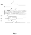
- the operating principle of the analyser is described in the following with reference to the timing diagram of Fig. 2 .
- the voltage pulses 12 occurring on Signal_IN is illustrated as a square wave pulse.
- the pulses have varying pulse shapes with varying peak amplitudes, and varying pulse width.
- the active filter 14 filters the input pulses 12, and the filtered output pulses 16 on the Signal_OUT line have a constant delay D1 between the peak amplitude 24 and the start of the rising edge of the pulses 16. D1 is independent of the peak amplitude of the pulses 12, 16. The ratio between the peak amplitude 24 of the filtered pulses 16 and the peak amplitude of respective input pulses 12 is substantially constant. As illustrated in Fig. 2 , the pulse width of the output pulses is less than the pulse width of the input pulses. The determination of the pulse height 12 is independent of the pulse width of the input pulse 12.
- the filtered output pulses 16 are provided to the N comparator & latches 18 with N thresholds.
- THP 1, 2, ... , N
- the corresponding latched output QP e.g. Q2
- the latched outputs Q1, Q2, ... , QN that correspond to the thresholds TH1, TH2, ..., THN having been exceeded by the pulse in question are set.
- the latched outputs Q1, Q2, and Q3 are set.
- the N-Line to X-Line priority encoder 20 converts Q N -Q 1 to a binary identifier A X -A 1 .
- the number of identifier bits is reduced. For example three identifier bits may identify up to 8 threshold voltages, four identifier bits may identify up to 16 threshold voltages, etc.
- the latch output Q 1 is connected to INT instead of EO in order to eliminate interrupts on the trailing edge of pulse 16 in case pulse 16 is noisy.
- the micro controller 22 contains a counter for each pulse height category so that the number of pulses occurring within each category may be counted.
- the micro controller 22 Upon interrupt, the micro controller 22 performs the following steps:
- Measurement START and STOP signal to the micro controller 22 are not show in Fig. 1 .
- the latches and priority encoder is embodied in a field programmable gate array (FPGA).
- FPGA field programmable gate array
- circuitry illustrated in Fig. 1 exclusive the micro controller 22, is embodied in a hybrid application specific integrated circuit (ASIC) containing analogue and digital circuitry.
- ASIC application specific integrated circuit
- Fig. 3 illustrates a circuit of a preferred embodiment for generation of threshold voltages.
- I o is the generated constant electrode current of 1.00 mA ⁇ 7 %.
- I o generates a voltage V o across R 1 .
- U 1a is a voltage follower, and U 2a generates the same voltage V o across R 13 so that I TH1 is substantially equal to I o .
- the threshold voltages P 1 to P 8 generated in the voltage divider R 16 to R 23 by I TH1 vary proportionally til V o but apart from this variation, the threshold voltages P 1 to P 8 are fixed. These threshold voltages are used for counting platelets (PLT).
- the output voltage of the voltage follower is voltage divided by the programmable potentiometer P 1 , and U 1b generates the divided voltage U P1 across R 2 ,
- the current generated through R 2 is mirrored into the voltage divider R 5 to R 12 generating the threshold voltages C, L, M, G 1 to G 5 .
- These threshold voltages are used for categorization of white blood cells (WBC). It should be noted that these threshold voltages vary proportionally to I o and that they are also adjustable via the control line U/D TH(X) for digital up/down adjustment of the potentiometer P 1 . The adjustment is performed during calibration as described below.
- the aperture resides in a polymer membrane and is precision machined.
- the aperture is machined with a UV-laser to provide an aperture diameter of 36 ⁇ m with a tolerance of ⁇ 2 %.
- the aperture to aperture diameter variation ( ⁇ 2 %) generates a pulse height tolerance of the electronic pulses of ⁇ 4 %, since the pulse height is proportional to the cross sectional area of the aperture, and therefore, it is preferred to calibrate the instrument before particle size determination.
Landscapes
- Chemical & Material Sciences (AREA)
- Dispersion Chemistry (AREA)
- Physics & Mathematics (AREA)
- Health & Medical Sciences (AREA)
- Life Sciences & Earth Sciences (AREA)
- Analytical Chemistry (AREA)
- Biochemistry (AREA)
- General Health & Medical Sciences (AREA)
- General Physics & Mathematics (AREA)
- Immunology (AREA)
- Pathology (AREA)
- Investigating Or Analysing Biological Materials (AREA)
- Investigating Or Analyzing Materials By The Use Of Electric Means (AREA)
Description
- The present invention relates to a particle characterisation apparatus in which particles suspended in a liquid are passed through an orifice, in principle one by one, to enable the characterisation of the particles, for instance by Coulter counting.
- It is well-known that particles travelling through a small orifice can be characterised with respect to size, concentration and conductivity by the use of an electrical impedance technique, widely known as the Coulter sizing (see V. Kachel, "Electrical Resistance Pulse Sizing: Coulter Sizing", Flow Cytometry and Sorting, Second Edition, pp. 45-80, 1990 Wiley-Liss).
- Counting and sizing of particles by the Coulter principle is an internationally respected method that is being used in most haematology-analysers and particle counting equipment. The method is based on measurable changes in the electrical impedance produced by nonconductive particles in an electrolyte. A small opening, called the "aperture" or "orifice", connects two electrically isolated chambers, where electrodes have been provided to contact the electrolyte. The orifice applies a restriction to the electrical path, whereby a sensing zone is established through which the particles are aspirated. In the sensing zone each particle will give rise to a displacement of the surrounding electrolyte, thus blocking part of the current-path and giving rise to a voltage pulse. By this method several thousand particles per second can be characterised with high precision.
- It is also well-known that the peak amplitude of the voltage pulses generated by the particles are closely correlated to the size of the particles, and therefore it is desirable to be able to determine the peak amplitude of voltage pulses in a simple and reliable way and at a low cost.
- An exemplary method for analysing a particle size and corresponding device are disclosed in
NL7 102 426 A - According to the present invention these and other objects are fulfilled by a particle characterization apparatus comprising a pulse height analyser for determination of the pulse height distribution of electronic pulses for determination of the particle size distribution of particles suspended in a liquid wherein the pulse height of each pulse is determined by recording of the passage of a set of voltage thresholds by the positive going edge of the pulse. The maximum threshold exceeded by the pulse characterises the peak amplitude of the pulse. Identification of the maximum exceeded threshold is input to a micro controller that is adapted to count the number of pulses within a pulse height category. A pulse height category consists of pulses with a pulse height within a pulse height interval defined between respective threshold voltages.
- Thus, the pulse height analyser may comprise a set of comparators with a common input that is provided with the electronic pulses.
- Further, the pulse height analyser may comprise a set of latches wherein the inputs of the latches are connected to the outputs of respective comparators for recording passage of the corresponding threshold voltages by the rising edge of a pulse.
- Identification of the set latched comparator outputs is input to the micro controller.
- A priority encoder may be connected to the latch outputs for determination of a pulse height category consisting of pulses with a specific maximum exceeded threshold voltage. This minimises the number of inputs to the micro controller for provision of the category identification.
- Further, the pulse height analyser may comprise a filter for provision of a substantially constant delay from pulse start to maximum pulse amplitude of the filtered pulse so that the time from pulse start to recording of the peak pulse amplitude is fixed whereby the electronic circuitry and especially the micro controller software handling the recorded measurement and controlling termination of the recording is simplified.
- The filter may be designed so that the output signal from the filter substantially has no DC-component. For example, the filter may differentiate the electronic pulses. Then, the filter output signal will contain a positive peak caused by the leading edge of an input pulse, and a negative peak caused by the trailing edge of the input pulse. The DC-components of the positive and negative peaks substantially cancel each other so that the resulting DC-component of the filter output signal substantially equals zero. This eliminates a need for a restoration circuit to compensate for possible DC baseline variations in the filter output signal due to variations in the mean value of the input signal containing the electronic pulses.
- It is an important advantage of the present invention that the threshold voltages may be individually adjusted as desired. For example, it is not required that the threshold voltages are equidistant. If the possible sizes of the particles are known, it is possible to select a minimum number of threshold voltages that are adjusted for optimum determination of the size distribution of the particles.
- For example, in analysis of whole blood, it is desirable to count the number of three types of blood cells erythrocytes, leukocytes and thrombocytes. Their size, expressed as equivalent diameter or volume, ranges from app. 1.2 µm or 1 fl (1 fl = 10-15l) for the smallest thrombocytes to app. 9 µm or 400 fl for the largest leukocytes.
- Information on the content of leukocytes, their subpopulations and thrombocytes is an important tool for the physician in order to diagnose different diseases and monitor treatment. Furthermore, the concentration of haemoglobin, directly related to the number of erythrocytes, in the blood sample is also of great importance.
- Thus, the number of erythrocytes, leukocytes and thrombocytes may be counted utilising the pulse height analyser of the present invention with threshold voltages that are selected and adjusted in accordance with the known sizes of the erythrocytes, leukocytes and thrombocytes, e.g. by positioning threshold voltages in between corresponding mean values of the individual particle size distributions.
- Preferably, the pulse height analyser also contains a current source, preferably a constant current source, for connection to the electrodes contacting the electrolyte in the two chambers mutually connected by the orifice. A particle passing through the orifice generates the electronic voltage pulse across the electrodes, which is supplied to the pulse height analyser. The peak value of the pulse is proportional to the volume of the particle and the value of the current.
- In a preferred embodiment of the invention, the threshold voltages of the comparators are made dependent on the actual value of the generated electrode current so that possible variations of the electrode current are substantially cancelled by corresponding variations of the thresholds. For example, the electrode current may be mirrored and the mirrored current supplied to a resistive voltage divider providing the threshold voltages. Then, e.g., a decrease in the generated electrode current is compensated by a corresponding decrease of the threshold voltages.
- The equivalent diameter of blood cells varies by a factor of app. 10 and thus, the volume of blood cells varies by a factor of app. 1000 so that the electronic pulses generated by the Coulter principle have a significant dynamic range. In order to lower the corresponding voltage range of the threshold voltages of the comparators, the comparators may be grouped in two or more sets of comparators, each set of comparators having a common signal input. Each signal input may be connected to an amplifier for amplification of the electronic pulses with an individual gain. Thus, considering the set of comparators connected to the amplifier with the largest gain, if the maximum amplified input pulse does not exceed the maximum threshold voltage of these comparators, the outputs of the comparators are used for determination of pulse height distribution. However, if the maximum threshold voltage is exceeded, then the next set of comparators connected to the next largest gain is used for determination of pulse height distribution, unless the maximum threshold voltage of these comparators is exceeded by the respective amplified input pulse, etc.
- Having determined and recorded the pulse height, the latches are reset whereby the pulse height analyser is made ready for pulse height determination of the next pulse. A latch-reset pulse may be generated a predetermined and fixed time period after pulse start.
- In the following the invention will be further described and illustrated with reference to the accompanying drawings in which:
- Fig. 1
- is a blocked diagram of a preferred embodiment of the present invention,
- Fig. 2
- is a timing diagram illustrating the operation of the embodiment shown in
Fig. 1 , and - Fig. 3
- shows a circuit diagram of an electronic circuit for generation of threshold voltages derived from the electrode current.
-
Fig. 1 is a blocked diagram of apulse height analyser 10 according to the present invention. The amplitude and frequency count of voltage pulses on the Signal_IN line is determined with the illustratedpulse height analyser 10. The operating principle of the analyser is described in the following with reference to the timing diagram ofFig. 2 . - In
Fig. 2 , thevoltage pulses 12 occurring on Signal_IN is illustrated as a square wave pulse. Typically, the pulses have varying pulse shapes with varying peak amplitudes, and varying pulse width. - The
active filter 14 filters theinput pulses 12, and the filteredoutput pulses 16 on the Signal_OUT line have a constant delay D1 between thepeak amplitude 24 and the start of the rising edge of thepulses 16. D1 is independent of the peak amplitude of thepulses peak amplitude 24 of the filteredpulses 16 and the peak amplitude ofrespective input pulses 12 is substantially constant. As illustrated inFig. 2 , the pulse width of the output pulses is less than the pulse width of the input pulses. The determination of thepulse height 12 is independent of the pulse width of theinput pulse 12. - The filtered
output pulses 16 are provided to the N comparator & latches 18 with N thresholds. When the rising edge of the filteredpulse 16 passes a specific threshold THP (P = 1, 2, ... , N), e.g. threshold TH2 inFig. 2 , the corresponding latched output QP, e.g. Q2, is set. Thus, after D1 the latched outputs Q1, Q2, ... , QN that correspond to the thresholds TH1, TH2, ..., THN having been exceeded by the pulse in question are set. For example, inFig. 2 , the latched outputs Q1, Q2, and Q3 are set. - The N-Line to
X-Line priority encoder 20 converts QN-Q1 to a binary identifier AX-A1. In the example ofFig. 2 , QN-Q1 = 0...0111 is converted to binary AX-A1 = 0...0011. Thus the number of identifier bits is reduced. For example three identifier bits may identify up to 8 threshold voltages, four identifier bits may identify up to 16 threshold voltages, etc. - The Enable Output (EO) interrupts (INT) the micro controller 22 at the positive transition of EO generated when the rising edge of
pulse 16 passes TH1. In a preferred embodiment, the latch output Q1 is connected to INT instead of EO in order to eliminate interrupts on the trailing edge ofpulse 16 incase pulse 16 is noisy. - The micro controller 22 contains a counter for each pulse height category so that the number of pulses occurring within each category may be counted. Preferably, consecutive threshold voltages define a pulse height category, i.e.
output pulses 16 with peak amplitudes between thresholds TH1 and TH2 for which Q1 is set (QN...Q2Q1 = 0...0001) constitutes one pulse height category, andoutput pulses 16 with peak amplitudes between thresholds TH2 and TH3 for which Q1 and Q2 is set (QN...Q2Q1 = 0...0011) constitutes the next pulse height category, etc. - Upon interrupt, the micro controller 22 performs the following steps:
- 1) Wait D2 > D1 so that AX-A1 is stable (cf.
Fig. 2 ), - 2) READ AX...A3A2A1 (0...0011 in the example of
Fig. 2 ), - 3) Increment by one the counter in the micro controller 22 that counts the number of
pulses 16 with the same peak amplitude recording, e.g. in the example ofFig. 2 , the counter counting the number ofpulses 16 with apeak amplitude 24 ranging from TH3 to TH4, and - 4) Send CLR to the latches and the circuit is ready to receive the next pulse.
- This procedure is repeated and executed in the measurement window. Measurement START and STOP signal to the micro controller 22 are not show in
Fig. 1 . - The
priority encoder 20 may be realised with a 74HC148 8-Line to 3-Line priority encoder for N = 8 and X = 3. - Two 74HC148 8-Line to 3-Line Priority Encoder and three 2-input AND gates may be interconnected for provision of four binary identification bits, i.e. N = 16 and X = 4 as is well known in the art.
- Likewise, as is also well-known in the art, 4 or 8 or 16 etc 74HC148 8-Line to 3-Line priority encoders and 3+4 = 7 or 7+5 = 12 or 12+6 = 18 etc 2-input AND gates may be interconnected for provision of five, six or seven, respectively, binary identification bits, i.e. N = 32, 64, or 128, and X= 5, 6, or 7, respectively.
- In another embodiment of the present invention, the latches and priority encoder is embodied in a field programmable gate array (FPGA).
- In yet another embodiment of the present invention, the circuitry illustrated in
Fig. 1 , exclusive the micro controller 22, is embodied in a hybrid application specific integrated circuit (ASIC) containing analogue and digital circuitry. -
Fig. 3 illustrates a circuit of a preferred embodiment for generation of threshold voltages. Io is the generated constant electrode current of 1.00 mA ± 7 %. Io generates a voltage Vo across R1. U1a is a voltage follower, and U2a generates the same voltage Vo across R13 so that ITH1 is substantially equal to Io. It should be noted that the threshold voltages P1 to P8 generated in the voltage divider R16 to R23 by ITH1 vary proportionally til Vo but apart from this variation, the threshold voltages P1 to P8 are fixed. These threshold voltages are used for counting platelets (PLT). - Further, the output voltage of the voltage follower is voltage divided by the programmable potentiometer P1, and U1b generates the divided voltage UP1 across R2, The current generated through R2 is mirrored into the voltage divider R5 to R12 generating the threshold voltages C, L, M, G1 to G5. These threshold voltages are used for categorization of white blood cells (WBC). It should be noted that these threshold voltages vary proportionally to Io and that they are also adjustable via the control line U/D TH(X) for digital up/down adjustment of the potentiometer P1. The adjustment is performed during calibration as described below.
- In a preferred embodiment of the present invention, the aperture resides in a polymer membrane and is precision machined. Preferably, the aperture is machined with a UV-laser to provide an aperture diameter of 36 µm with a tolerance of ± 2 %. The aperture to aperture diameter variation (± 2 %) generates a pulse height tolerance of the electronic pulses of ± 4 %, since the pulse height is proportional to the cross sectional area of the aperture, and therefore, it is preferred to calibrate the instrument before particle size determination.
Claims (7)
- A particle characterization apparatus comprising:- two electrically isolated chambers for holding an electrolyte, the chambers being connected by an orifice;- electrodes for contacting the electrolyte in the chambers and for detecting electronic pulses when particles comprised in the electrolyte are passed through the orifice,characterized in that the particle characterization apparatus further comprises:- a pulse height analyser (10) adapted to determine the particle size distribution of the particles comprising:a set of comparators (18) with a common input for analogue to digital conversion of the electronic pulses,a set of latches (18) wherein the inputs of the latches are connected to the outputs of respective comparators for recording passage of the corresponding threshold voltages (TH1...THN) by the rising edge of a pulse,a priority encoder (20) connected to the latch outputs (Q1...QN) for determination of a pulse height category (A1...AX) consisting of pulses with a pulse height within a pulse height interval defined by respective threshold voltages, anda micro controller (22) that is adapted to count the number of pulses within each pulse height category.
- A particle characterization apparatus according to claim 1, wherein the thresholds (TH1...THN) of the comparators (18) are non-equidistant.
- A particle characterization apparatus according to claim 1, further comprising a filter (14) for filtering the electronic pulses (12) providing a substantially constant delay (D1) from pulse start to maximum pulse amplitude (24) of the filtered pulse (16), and for provision of the filtered pulses to the common input of the comparators.
- A particle characterization apparatus according to claim 1, further comprising a filter (14) for filtering the electronic pulses (12) providing an output signal containing the filtered pulses with a DC-value substantially equal to zero.
- A particle characterization apparatus according to any of the preceding claims, further comprising a current source, preferably a constant current source, for connection to electrodes contacting an electrolyte in two chambers mutually connected by an orifice for Coulter counting of particles, and wherein the thresholds (TH1...THN) of the comparators (18) are dependent on the actual value of the generated electrode current whereby possible variations of the electrode current are substantially cancelled by corresponding variations of the thresholds.
- A particle characterization apparatus according to any of the preceding claims, further comprising a plurality of sets of comparators (18) for pulse height determination of input pulses of different amplification.
- A particle characterization apparatus according to any of the preceding claims, further comprising circuitry for resetting the latches (18) a predetermined time period after start of a pulse, the time period being independent of the pulse height and the pulse width.
Applications Claiming Priority (2)
| Application Number | Priority Date | Filing Date | Title |
|---|---|---|---|
| DKPA200301257 | 2003-09-02 | ||
| PCT/DK2004/000568 WO2005022126A1 (en) | 2003-09-02 | 2004-08-27 | A pulse height analyser |
Publications (2)
| Publication Number | Publication Date |
|---|---|
| EP1664737A1 EP1664737A1 (en) | 2006-06-07 |
| EP1664737B1 true EP1664737B1 (en) | 2016-03-30 |
Family
ID=34259074
Family Applications (1)
| Application Number | Title | Priority Date | Filing Date |
|---|---|---|---|
| EP04762789.8A Expired - Lifetime EP1664737B1 (en) | 2003-09-02 | 2004-08-27 | A pulse height analyser |
Country Status (3)
| Country | Link |
|---|---|
| US (1) | US7701193B2 (en) |
| EP (1) | EP1664737B1 (en) |
| WO (1) | WO2005022126A1 (en) |
Families Citing this family (7)
| Publication number | Priority date | Publication date | Assignee | Title |
|---|---|---|---|---|
| US7928718B2 (en) | 2004-10-01 | 2011-04-19 | Chempaq A/S | Method for calibrating a particle counting apparatus |
| JP5473931B2 (en) * | 2007-11-16 | 2014-04-16 | パーティクル・メージャーリング・システムズ・インコーポレーテッド | System and method for calibration verification of an optical particle counter |
| JP5693973B2 (en) * | 2008-03-03 | 2015-04-01 | コーニンクレッカ フィリップス エヌ ヴェ | High resolution classification |
| WO2014159692A1 (en) | 2013-03-13 | 2014-10-02 | Tahoe Institute for Rural Health Research, LLC | Portable blood count monitor |
| JP2016070782A (en) * | 2014-09-30 | 2016-05-09 | 株式会社Jvcケンウッド | Analyzer and analysis method |
| RU2572063C1 (en) * | 2014-10-06 | 2015-12-27 | Российская Федерация, от имени которой выступает Государственная корпорация по атомной энергии "Росатом" - Госкорпорация "Росатом" | Device for detecting fission pulse shape |
| CN114460882A (en) * | 2022-02-11 | 2022-05-10 | 靖江市宇其光电科技有限公司 | Incremental encoder pulse detection circuit based on programmable logic array |
Citations (3)
| Publication number | Priority date | Publication date | Assignee | Title |
|---|---|---|---|---|
| NL7102426A (en) * | 1970-05-25 | 1971-11-29 | ||
| US3634688A (en) * | 1970-01-19 | 1972-01-11 | Baird Atomic Inc | Multimode spectral analyzer |
| WO1992016829A1 (en) * | 1991-03-18 | 1992-10-01 | The University Of Rochester | A system for high-speed measurement and sorting of particles |
Family Cites Families (15)
| Publication number | Priority date | Publication date | Assignee | Title |
|---|---|---|---|---|
| US3345502A (en) * | 1964-08-14 | 1967-10-03 | Robert H Berg | Pulse analyzer computer |
| DE1247051B (en) * | 1965-06-18 | 1967-08-10 | Siemens Ag | Circuit arrangement to compensate for changes in contrast when digitizing video signals |
| US3801904A (en) * | 1972-09-11 | 1974-04-02 | Coulter Electronics | Particle study apparatus including an axial trajectory sensor |
| US3790767A (en) * | 1972-12-04 | 1974-02-05 | A Alexander | Pulse analyzing tester |
| CA1002114A (en) * | 1973-04-18 | 1976-12-21 | Wallace H. Coulter | Apparatus and method for analyzing particle volume distribution |
| CA1082811A (en) * | 1976-04-05 | 1980-07-29 | Greenwood Mills, Inc. | Diffraction pattern amplitude analysis for use in fabric inspection |
| US4218610A (en) * | 1976-04-28 | 1980-08-19 | J. T. Baker Chemical Co. | Automatic blood analyzing system |
| IT1119341B (en) * | 1979-08-02 | 1986-03-10 | Cselt Centro Studi Lab Telecom | IMPULSIVE VOLTAGE ANALYZER |
| US4541070A (en) * | 1982-11-04 | 1985-09-10 | Musin Rafail M | Pulse characteristic meter |
| CA1219086A (en) * | 1983-08-19 | 1987-03-10 | Kazuhiro Iinuma | Radiation imaging apparatus |
| US4817208A (en) * | 1987-09-08 | 1989-03-28 | Westinghouse Electric Corp. | Fiber optic receiver |
| US5357331A (en) * | 1991-07-02 | 1994-10-18 | Flockencier Stuart W | System for processing reflected energy signals |
| US5528303A (en) * | 1993-11-01 | 1996-06-18 | Elantec, Inc. | Synchronizing signal active filter and method |
| US5719667A (en) * | 1996-07-30 | 1998-02-17 | Bayer Corporation | Apparatus for filtering a laser beam in an analytical instrument |
| US7818047B2 (en) * | 2001-11-09 | 2010-10-19 | Nova R&D, Inc. | X-ray and gamma ray detector readout system |
-
2004
- 2004-08-27 WO PCT/DK2004/000568 patent/WO2005022126A1/en not_active Ceased
- 2004-08-27 EP EP04762789.8A patent/EP1664737B1/en not_active Expired - Lifetime
- 2004-08-27 US US10/570,150 patent/US7701193B2/en not_active Expired - Fee Related
Patent Citations (3)
| Publication number | Priority date | Publication date | Assignee | Title |
|---|---|---|---|---|
| US3634688A (en) * | 1970-01-19 | 1972-01-11 | Baird Atomic Inc | Multimode spectral analyzer |
| NL7102426A (en) * | 1970-05-25 | 1971-11-29 | ||
| WO1992016829A1 (en) * | 1991-03-18 | 1992-10-01 | The University Of Rochester | A system for high-speed measurement and sorting of particles |
Non-Patent Citations (1)
| Title |
|---|
| "Introduction to Radiation Detectors and Electronics", 31 December 1998, UC BERKLEY, article HELMUTH SPIELER: "Digitization of Pulse Height - Analog to Digital Conversion", XP055169059 * |
Also Published As
| Publication number | Publication date |
|---|---|
| US7701193B2 (en) | 2010-04-20 |
| EP1664737A1 (en) | 2006-06-07 |
| WO2005022126A1 (en) | 2005-03-10 |
| US20070200548A1 (en) | 2007-08-30 |
Similar Documents
| Publication | Publication Date | Title |
|---|---|---|
| JP2815435B2 (en) | Particle analyzer and blood cell counter | |
| JP5557842B2 (en) | Simultaneous detection and processing in particle analysis | |
| US4086631A (en) | Hematocrit measurement in an automatic hematology analyzer | |
| US4412175A (en) | Debris alarm | |
| AU578166B2 (en) | Editing particle produced electrical pulses | |
| US7701193B2 (en) | Pulse height analyser | |
| US3863056A (en) | Method and apparatus for multichannel voting | |
| CN113227757B (en) | A blood cell parameter correction method, blood sample detector and storage medium | |
| US3961249A (en) | Particle size distribution analyzation employing trailing edge differentiation | |
| GB1588170A (en) | Apparatus for and method of measuring particle concentration | |
| AU2005291725B2 (en) | A method for calibrating a particle counting apparatus | |
| US20110027825A1 (en) | High resolution classification | |
| KR102672881B1 (en) | Method for measuring particles in solution and apparatus for performing the same method | |
| Bacus et al. | Clinical evaluation of a new electrical impedance instrument for counting platelets in whole blood | |
| US4307339A (en) | Particle counter | |
| EP4465016A1 (en) | Method for measuring particles in solution and device for performing same | |
| Larsen et al. | Somatic Cell Counting with Silicon Apertures | |
| JPH0352821B2 (en) | ||
| JPH0479531B2 (en) | ||
| Cho et al. | Bio-inspired cell concentration and Deformability monitoring chips | |
| JPH0146818B2 (en) | ||
| JPS61196135A (en) | Method and device for compensating coexistent error | |
| JPS6129461B2 (en) | ||
| JPS59148849A (en) | Particle counter |
Legal Events
| Date | Code | Title | Description |
|---|---|---|---|
| PUAI | Public reference made under article 153(3) epc to a published international application that has entered the european phase |
Free format text: ORIGINAL CODE: 0009012 |
|
| 17P | Request for examination filed |
Effective date: 20060403 |
|
| AK | Designated contracting states |
Kind code of ref document: A1 Designated state(s): AT BE BG CH CY CZ DE DK EE ES FI FR GB GR HU IE IT LI LU MC NL PL PT RO SE SI SK TR |
|
| DAX | Request for extension of the european patent (deleted) | ||
| 17Q | First examination report despatched |
Effective date: 20080215 |
|
| RAP1 | Party data changed (applicant data changed or rights of an application transferred) |
Owner name: KONINKLIJKE PHILIPS ELECTRONICS N.V. |
|
| RAP1 | Party data changed (applicant data changed or rights of an application transferred) |
Owner name: KONINKLIJKE PHILIPS N.V. |
|
| GRAP | Despatch of communication of intention to grant a patent |
Free format text: ORIGINAL CODE: EPIDOSNIGR1 |
|
| INTG | Intention to grant announced |
Effective date: 20151008 |
|
| GRAS | Grant fee paid |
Free format text: ORIGINAL CODE: EPIDOSNIGR3 |
|
| GRAA | (expected) grant |
Free format text: ORIGINAL CODE: 0009210 |
|
| AK | Designated contracting states |
Kind code of ref document: B1 Designated state(s): AT BE BG CH CY CZ DE DK EE ES FI FR GB GR HU IE IT LI LU MC NL PL PT RO SE SI SK TR |
|
| REG | Reference to a national code |
Ref country code: GB Ref legal event code: FG4D |
|
| REG | Reference to a national code |
Ref country code: CH Ref legal event code: EP |
|
| REG | Reference to a national code |
Ref country code: AT Ref legal event code: REF Ref document number: 785909 Country of ref document: AT Kind code of ref document: T Effective date: 20160415 |
|
| REG | Reference to a national code |
Ref country code: IE Ref legal event code: FG4D |
|
| REG | Reference to a national code |
Ref country code: DE Ref legal event code: R096 Ref document number: 602004048929 Country of ref document: DE |
|
| PG25 | Lapsed in a contracting state [announced via postgrant information from national office to epo] |
Ref country code: GR Free format text: LAPSE BECAUSE OF FAILURE TO SUBMIT A TRANSLATION OF THE DESCRIPTION OR TO PAY THE FEE WITHIN THE PRESCRIBED TIME-LIMIT Effective date: 20160701 Ref country code: FI Free format text: LAPSE BECAUSE OF FAILURE TO SUBMIT A TRANSLATION OF THE DESCRIPTION OR TO PAY THE FEE WITHIN THE PRESCRIBED TIME-LIMIT Effective date: 20160330 |
|
| REG | Reference to a national code |
Ref country code: NL Ref legal event code: MP Effective date: 20160330 |
|
| REG | Reference to a national code |
Ref country code: AT Ref legal event code: MK05 Ref document number: 785909 Country of ref document: AT Kind code of ref document: T Effective date: 20160330 |
|
| PG25 | Lapsed in a contracting state [announced via postgrant information from national office to epo] |
Ref country code: SE Free format text: LAPSE BECAUSE OF FAILURE TO SUBMIT A TRANSLATION OF THE DESCRIPTION OR TO PAY THE FEE WITHIN THE PRESCRIBED TIME-LIMIT Effective date: 20160330 |
|
| PG25 | Lapsed in a contracting state [announced via postgrant information from national office to epo] |
Ref country code: NL Free format text: LAPSE BECAUSE OF FAILURE TO SUBMIT A TRANSLATION OF THE DESCRIPTION OR TO PAY THE FEE WITHIN THE PRESCRIBED TIME-LIMIT Effective date: 20160330 |
|
| PG25 | Lapsed in a contracting state [announced via postgrant information from national office to epo] |
Ref country code: PL Free format text: LAPSE BECAUSE OF FAILURE TO SUBMIT A TRANSLATION OF THE DESCRIPTION OR TO PAY THE FEE WITHIN THE PRESCRIBED TIME-LIMIT Effective date: 20160330 Ref country code: EE Free format text: LAPSE BECAUSE OF FAILURE TO SUBMIT A TRANSLATION OF THE DESCRIPTION OR TO PAY THE FEE WITHIN THE PRESCRIBED TIME-LIMIT Effective date: 20160330 |
|
| PG25 | Lapsed in a contracting state [announced via postgrant information from national office to epo] |
Ref country code: SK Free format text: LAPSE BECAUSE OF FAILURE TO SUBMIT A TRANSLATION OF THE DESCRIPTION OR TO PAY THE FEE WITHIN THE PRESCRIBED TIME-LIMIT Effective date: 20160330 Ref country code: ES Free format text: LAPSE BECAUSE OF FAILURE TO SUBMIT A TRANSLATION OF THE DESCRIPTION OR TO PAY THE FEE WITHIN THE PRESCRIBED TIME-LIMIT Effective date: 20160330 Ref country code: AT Free format text: LAPSE BECAUSE OF FAILURE TO SUBMIT A TRANSLATION OF THE DESCRIPTION OR TO PAY THE FEE WITHIN THE PRESCRIBED TIME-LIMIT Effective date: 20160330 Ref country code: RO Free format text: LAPSE BECAUSE OF FAILURE TO SUBMIT A TRANSLATION OF THE DESCRIPTION OR TO PAY THE FEE WITHIN THE PRESCRIBED TIME-LIMIT Effective date: 20160330 Ref country code: PT Free format text: LAPSE BECAUSE OF FAILURE TO SUBMIT A TRANSLATION OF THE DESCRIPTION OR TO PAY THE FEE WITHIN THE PRESCRIBED TIME-LIMIT Effective date: 20160801 Ref country code: CZ Free format text: LAPSE BECAUSE OF FAILURE TO SUBMIT A TRANSLATION OF THE DESCRIPTION OR TO PAY THE FEE WITHIN THE PRESCRIBED TIME-LIMIT Effective date: 20160330 |
|
| PG25 | Lapsed in a contracting state [announced via postgrant information from national office to epo] |
Ref country code: BE Free format text: LAPSE BECAUSE OF FAILURE TO SUBMIT A TRANSLATION OF THE DESCRIPTION OR TO PAY THE FEE WITHIN THE PRESCRIBED TIME-LIMIT Effective date: 20160330 Ref country code: IT Free format text: LAPSE BECAUSE OF FAILURE TO SUBMIT A TRANSLATION OF THE DESCRIPTION OR TO PAY THE FEE WITHIN THE PRESCRIBED TIME-LIMIT Effective date: 20160330 |
|
| REG | Reference to a national code |
Ref country code: DE Ref legal event code: R097 Ref document number: 602004048929 Country of ref document: DE |
|
| PG25 | Lapsed in a contracting state [announced via postgrant information from national office to epo] |
Ref country code: DK Free format text: LAPSE BECAUSE OF FAILURE TO SUBMIT A TRANSLATION OF THE DESCRIPTION OR TO PAY THE FEE WITHIN THE PRESCRIBED TIME-LIMIT Effective date: 20160330 |
|
| PLBE | No opposition filed within time limit |
Free format text: ORIGINAL CODE: 0009261 |
|
| STAA | Information on the status of an ep patent application or granted ep patent |
Free format text: STATUS: NO OPPOSITION FILED WITHIN TIME LIMIT |
|
| 26N | No opposition filed |
Effective date: 20170103 |
|
| PG25 | Lapsed in a contracting state [announced via postgrant information from national office to epo] |
Ref country code: MC Free format text: LAPSE BECAUSE OF FAILURE TO SUBMIT A TRANSLATION OF THE DESCRIPTION OR TO PAY THE FEE WITHIN THE PRESCRIBED TIME-LIMIT Effective date: 20160330 |
|
| REG | Reference to a national code |
Ref country code: CH Ref legal event code: PL |
|
| PG25 | Lapsed in a contracting state [announced via postgrant information from national office to epo] |
Ref country code: CH Free format text: LAPSE BECAUSE OF NON-PAYMENT OF DUE FEES Effective date: 20160831 Ref country code: LI Free format text: LAPSE BECAUSE OF NON-PAYMENT OF DUE FEES Effective date: 20160831 |
|
| REG | Reference to a national code |
Ref country code: FR Ref legal event code: ST Effective date: 20170428 |
|
| PG25 | Lapsed in a contracting state [announced via postgrant information from national office to epo] |
Ref country code: SI Free format text: LAPSE BECAUSE OF FAILURE TO SUBMIT A TRANSLATION OF THE DESCRIPTION OR TO PAY THE FEE WITHIN THE PRESCRIBED TIME-LIMIT Effective date: 20160330 |
|
| REG | Reference to a national code |
Ref country code: IE Ref legal event code: MM4A |
|
| PG25 | Lapsed in a contracting state [announced via postgrant information from national office to epo] |
Ref country code: FR Free format text: LAPSE BECAUSE OF NON-PAYMENT OF DUE FEES Effective date: 20160831 Ref country code: IE Free format text: LAPSE BECAUSE OF NON-PAYMENT OF DUE FEES Effective date: 20160827 |
|
| PG25 | Lapsed in a contracting state [announced via postgrant information from national office to epo] |
Ref country code: LU Free format text: LAPSE BECAUSE OF NON-PAYMENT OF DUE FEES Effective date: 20160827 |
|
| PG25 | Lapsed in a contracting state [announced via postgrant information from national office to epo] |
Ref country code: CY Free format text: LAPSE BECAUSE OF FAILURE TO SUBMIT A TRANSLATION OF THE DESCRIPTION OR TO PAY THE FEE WITHIN THE PRESCRIBED TIME-LIMIT Effective date: 20160330 Ref country code: HU Free format text: LAPSE BECAUSE OF FAILURE TO SUBMIT A TRANSLATION OF THE DESCRIPTION OR TO PAY THE FEE WITHIN THE PRESCRIBED TIME-LIMIT; INVALID AB INITIO Effective date: 20040827 |
|
| PG25 | Lapsed in a contracting state [announced via postgrant information from national office to epo] |
Ref country code: TR Free format text: LAPSE BECAUSE OF FAILURE TO SUBMIT A TRANSLATION OF THE DESCRIPTION OR TO PAY THE FEE WITHIN THE PRESCRIBED TIME-LIMIT Effective date: 20160330 |
|
| PG25 | Lapsed in a contracting state [announced via postgrant information from national office to epo] |
Ref country code: BG Free format text: LAPSE BECAUSE OF FAILURE TO SUBMIT A TRANSLATION OF THE DESCRIPTION OR TO PAY THE FEE WITHIN THE PRESCRIBED TIME-LIMIT Effective date: 20160330 |
|
| PGFP | Annual fee paid to national office [announced via postgrant information from national office to epo] |
Ref country code: GB Payment date: 20180831 Year of fee payment: 15 |
|
| PGFP | Annual fee paid to national office [announced via postgrant information from national office to epo] |
Ref country code: DE Payment date: 20181031 Year of fee payment: 15 |
|
| REG | Reference to a national code |
Ref country code: DE Ref legal event code: R119 Ref document number: 602004048929 Country of ref document: DE |
|
| GBPC | Gb: european patent ceased through non-payment of renewal fee |
Effective date: 20190827 |
|
| PG25 | Lapsed in a contracting state [announced via postgrant information from national office to epo] |
Ref country code: DE Free format text: LAPSE BECAUSE OF NON-PAYMENT OF DUE FEES Effective date: 20200303 |
|
| PG25 | Lapsed in a contracting state [announced via postgrant information from national office to epo] |
Ref country code: GB Free format text: LAPSE BECAUSE OF NON-PAYMENT OF DUE FEES Effective date: 20190827 |