EP1664558B1 - Fastening element to be anchored in a short blind hole that is not undercut, arrangement comprising such a fastening element, method and placement tool for anchoring such a fastening element - Google Patents
Fastening element to be anchored in a short blind hole that is not undercut, arrangement comprising such a fastening element, method and placement tool for anchoring such a fastening element Download PDFInfo
- Publication number
- EP1664558B1 EP1664558B1 EP04765435.5A EP04765435A EP1664558B1 EP 1664558 B1 EP1664558 B1 EP 1664558B1 EP 04765435 A EP04765435 A EP 04765435A EP 1664558 B1 EP1664558 B1 EP 1664558B1
- Authority
- EP
- European Patent Office
- Prior art keywords
- expansion sleeve
- cone
- expansion
- expander cone
- hole
- Prior art date
- Legal status (The legal status is an assumption and is not a legal conclusion. Google has not performed a legal analysis and makes no representation as to the accuracy of the status listed.)
- Not-in-force
Links
- 238000004873 anchoring Methods 0.000 title claims description 57
- 238000000034 method Methods 0.000 title description 5
- 229910000831 Steel Inorganic materials 0.000 claims description 11
- 230000004323 axial length Effects 0.000 claims description 11
- 239000010959 steel Substances 0.000 claims description 11
- 230000007704 transition Effects 0.000 claims description 4
- 230000001154 acute effect Effects 0.000 claims description 3
- 238000007789 sealing Methods 0.000 claims 1
- 229910000746 Structural steel Inorganic materials 0.000 description 16
- XAGFODPZIPBFFR-UHFFFAOYSA-N aluminium Chemical compound [Al] XAGFODPZIPBFFR-UHFFFAOYSA-N 0.000 description 7
- 229910052782 aluminium Inorganic materials 0.000 description 7
- 239000000463 material Substances 0.000 description 6
- 238000007788 roughening Methods 0.000 description 6
- 238000002604 ultrasonography Methods 0.000 description 6
- 229910001087 A-4 tool steel Inorganic materials 0.000 description 4
- 230000000694 effects Effects 0.000 description 4
- 229910001209 Low-carbon steel Inorganic materials 0.000 description 3
- 238000005260 corrosion Methods 0.000 description 3
- 230000007797 corrosion Effects 0.000 description 3
- 238000006243 chemical reaction Methods 0.000 description 2
- 230000018109 developmental process Effects 0.000 description 2
- 230000002093 peripheral effect Effects 0.000 description 2
- 239000000565 sealant Substances 0.000 description 2
- 239000007779 soft material Substances 0.000 description 2
- 239000010935 stainless steel Substances 0.000 description 2
- 229910001220 stainless steel Inorganic materials 0.000 description 2
- 229910000838 Al alloy Inorganic materials 0.000 description 1
- 230000004888 barrier function Effects 0.000 description 1
- 239000011324 bead Substances 0.000 description 1
- 230000000903 blocking effect Effects 0.000 description 1
- 230000000295 complement effect Effects 0.000 description 1
- 238000006073 displacement reaction Methods 0.000 description 1
- 230000005284 excitation Effects 0.000 description 1
- 230000002349 favourable effect Effects 0.000 description 1
- 239000000314 lubricant Substances 0.000 description 1
- 238000000465 moulding Methods 0.000 description 1
- 238000000926 separation method Methods 0.000 description 1
Images

Classifications
-
- F—MECHANICAL ENGINEERING; LIGHTING; HEATING; WEAPONS; BLASTING
- F16—ENGINEERING ELEMENTS AND UNITS; GENERAL MEASURES FOR PRODUCING AND MAINTAINING EFFECTIVE FUNCTIONING OF MACHINES OR INSTALLATIONS; THERMAL INSULATION IN GENERAL
- F16B—DEVICES FOR FASTENING OR SECURING CONSTRUCTIONAL ELEMENTS OR MACHINE PARTS TOGETHER, e.g. NAILS, BOLTS, CIRCLIPS, CLAMPS, CLIPS OR WEDGES; JOINTS OR JOINTING
- F16B13/00—Dowels or other devices fastened in walls or the like by inserting them in holes made therein for that purpose
- F16B13/04—Dowels or other devices fastened in walls or the like by inserting them in holes made therein for that purpose with parts gripping in the hole or behind the reverse side of the wall after inserting from the front
- F16B13/08—Dowels or other devices fastened in walls or the like by inserting them in holes made therein for that purpose with parts gripping in the hole or behind the reverse side of the wall after inserting from the front with separate or non-separate gripping parts moved into their final position in relation to the body of the device without further manual operation
- F16B13/0858—Dowels or other devices fastened in walls or the like by inserting them in holes made therein for that purpose with parts gripping in the hole or behind the reverse side of the wall after inserting from the front with separate or non-separate gripping parts moved into their final position in relation to the body of the device without further manual operation with an expansible sleeve or dowel body driven against a tapered or spherical expander plug
-
- F—MECHANICAL ENGINEERING; LIGHTING; HEATING; WEAPONS; BLASTING
- F16—ENGINEERING ELEMENTS AND UNITS; GENERAL MEASURES FOR PRODUCING AND MAINTAINING EFFECTIVE FUNCTIONING OF MACHINES OR INSTALLATIONS; THERMAL INSULATION IN GENERAL
- F16B—DEVICES FOR FASTENING OR SECURING CONSTRUCTIONAL ELEMENTS OR MACHINE PARTS TOGETHER, e.g. NAILS, BOLTS, CIRCLIPS, CLAMPS, CLIPS OR WEDGES; JOINTS OR JOINTING
- F16B13/00—Dowels or other devices fastened in walls or the like by inserting them in holes made therein for that purpose
- F16B13/04—Dowels or other devices fastened in walls or the like by inserting them in holes made therein for that purpose with parts gripping in the hole or behind the reverse side of the wall after inserting from the front
- F16B13/06—Dowels or other devices fastened in walls or the like by inserting them in holes made therein for that purpose with parts gripping in the hole or behind the reverse side of the wall after inserting from the front combined with expanding sleeve
- F16B13/063—Dowels or other devices fastened in walls or the like by inserting them in holes made therein for that purpose with parts gripping in the hole or behind the reverse side of the wall after inserting from the front combined with expanding sleeve by the use of an expander
- F16B13/065—Dowels or other devices fastened in walls or the like by inserting them in holes made therein for that purpose with parts gripping in the hole or behind the reverse side of the wall after inserting from the front combined with expanding sleeve by the use of an expander fastened by extracting the screw, nail or the like
-
- F—MECHANICAL ENGINEERING; LIGHTING; HEATING; WEAPONS; BLASTING
- F16—ENGINEERING ELEMENTS AND UNITS; GENERAL MEASURES FOR PRODUCING AND MAINTAINING EFFECTIVE FUNCTIONING OF MACHINES OR INSTALLATIONS; THERMAL INSULATION IN GENERAL
- F16B—DEVICES FOR FASTENING OR SECURING CONSTRUCTIONAL ELEMENTS OR MACHINE PARTS TOGETHER, e.g. NAILS, BOLTS, CIRCLIPS, CLAMPS, CLIPS OR WEDGES; JOINTS OR JOINTING
- F16B37/00—Nuts or like thread-engaging members
- F16B37/04—Devices for fastening nuts to surfaces, e.g. sheets, plates
- F16B37/048—Non-releasable devices
-
- F—MECHANICAL ENGINEERING; LIGHTING; HEATING; WEAPONS; BLASTING
- F16—ENGINEERING ELEMENTS AND UNITS; GENERAL MEASURES FOR PRODUCING AND MAINTAINING EFFECTIVE FUNCTIONING OF MACHINES OR INSTALLATIONS; THERMAL INSULATION IN GENERAL
- F16B—DEVICES FOR FASTENING OR SECURING CONSTRUCTIONAL ELEMENTS OR MACHINE PARTS TOGETHER, e.g. NAILS, BOLTS, CIRCLIPS, CLAMPS, CLIPS OR WEDGES; JOINTS OR JOINTING
- F16B37/00—Nuts or like thread-engaging members
- F16B37/12—Nuts or like thread-engaging members with thread-engaging surfaces formed by inserted coil-springs, discs, or the like; Independent pieces of wound wire used as nuts; Threaded inserts for holes
- F16B37/122—Threaded inserts, e.g. "rampa bolts"
Definitions
- the invention relates to a fastener for anchoring in a short, not undercut blind hole according to the preamble of claim 1 and an arrangement with such a fastener according to the preamble of claim 12.
- the fastener is particularly intended to provide a mounting option on a plate-shaped component, for example made of structural steel to be able to attach another component to it.
- the plate-shaped component should not be pierced, which is why only a relatively short anchoring depth is available, especially when a diameter of the blind hole is approximately the same size as a thickness of the component. Short is to be understood in relation to the diameter of the blind hole.
- FR 1 297 330 A From the FR 1 297 330 A is a fastener with an expansion sleeve and a hollow round expanding expansion known, which is integral with a shaft or in which a shaft is screwed.
- the expansion sleeve has a bell-shaped mouth in the area which is pushed onto the spigot for spreading.
- the disadvantage is that the expansion sleeve rests only linearly along a circumferential line with its bell-shaped expansion on the expansion body. It is therefore pressed only in a narrow, circumferential area to the outside and supported by the spreader. A possible large-scale, with force to the outside pressed system on a wall of the blind hole is thus not reachable.
- a mouth region of the expansion sleeve is sharp-edged and thin-walled and is not supported in the spread state of the spreader, the mouth area therefore contributes to the anchoring virtually nothing. In a hard material, the expansion sleeve does not form.
- the expansion sleeve of GB 743 651 A has an edge jagged in the manner of a crown.
- the spikes press into the hole wall during spreading, which is also possible only in a soft material.
- the fastener of FR 2 289 789 A see preamble of claim 1 or 12 of the present invention has an expansion cone, which is connected at its rear end via a peripheral predetermined breaking point with a tubular expansion sleeve.
- the rear end is the smaller diameter end of the expansion cone, which is hollow and has an internal thread.
- a disadvantage is that the expansion sleeve is pushed into the borehole only during spreading, it does not reach the bottom of the hole. For a short blind hole, the fastener is therefore not suitable.
- An anchoring in the mouth area of a blind hole has lower holding values than anchoring at the bottom of the blind hole.
- the US 4,919,579 A discloses an undercut expansion anchor with a slotted expansion sleeve. which is anchored with a conical expansion body in a hollow conical undercut of a blind hole. This anchorage requires an undercut hole.
- the invention is therefore based on the object to propose a fastener which can be fastened in a non-undercut blind hole. It should be sufficient in relation to the diameter short blind hole for attachment.
- the inventive fastener has a tubular, ungrounded expansion sleeve, which is located on the shaft and is displaceable on the shaft.
- the fastener with the expansion cone is used in advance in the blind hole and pushed the expansion sleeve on the expansion cone.
- the expansion cone expands the expansion sleeve in their spreader cone facing end region.
- the widened end region presses into a hole wall of the blind hole and thereby anchors the fastening element in the blind hole.
- the result is a positive and non-positive connection between the expanded in the front end of the expansion sleeve and the blind hole, whereby a high anchoring force is achieved even in a short blind hole.
- Another advantage of the fastener according to the invention is a support of its shaft against transverse forces through the expansion sleeve in the borehole. Furthermore, a flush-mounted in the blind hole expansion sleeve indicates a correct anchoring of the fastener, if the blind hole has a predetermined desired depth.
- the fastening element according to the invention is intended in particular for anchoring in structural steel, aluminum or the like, but it is suitable also for anchoring in other materials, such as concrete. In order to facilitate the sliding of the expansion sleeve on the expansion cone and thereby causing expansion of the expansion sleeve of the expansion cone may be provided with a lubricant.
- expansion sleeve in its spreader cone facing end portion is a hollow conical widening in the manner of a chamfer or an inner cone on an inner side of the expansion cone facing end side of the expansion sleeve.
- a material thickness of the expansion sleeve is thereby reduced in the expanding on the expansion cone when pushing on the front region of the expansion sleeve, whereby the expansion sleeve can expand with less force.
- the hollow conical widening of the expansion sleeve has a more acute cone angle than the expansion cone.
- the expansion sleeve when pushed onto the expansion cone, the expansion sleeve first comes into contact with the expansion cone with its front end facing the expansion cone.
- the expansion sleeve is first widened in its front end area and pressed into the hole wall. Only with increasing pushing on the expansion cone, the widening of the expansion sleeve continues from the front, the expansion cone facing end region beginning in an approximately central region of the axially short expansion sleeve.
- the widening of the expansion sleeve in the front end region has the advantage that a Friedweitkraft is small, because the expansion sleeve is expanded only over a short part of its axial length, and that the force with which the expansion sleeve is pressed into the hole wall, because the expansion sleeve is pressed only in the front end region and thus with a comparatively small annular surface in the hole wall.
- the advantage is a stable anchoring at a comparatively low Aufweitkraft. This effect is supported by a thin-walled expansion sleeve
- a cone angle of the expansion cone in the range of about 14 ° to 20 °, preferably of about 17 ° has been found to be favorable.
- An embodiment of the invention provides a roughening on an outer side of the expansion sleeve, at least in their end region facing the expansion cone.
- the roughening can be, for example, a cross knurl, unsuitable is a line-shaped roughening when it is parallel to the axis.
- the roughening when made by forming such as knurling, causes a surface hardening of the expansion sleeve. As a result, the roughening is pressed into the hole wall even when the expansion sleeve and a component having the blind hole are made of materials originally of the same hardness.
- the expansion sleeve to a steel of great hardness for example, it is made of an alloyed, stainless steel (for example, A4 steel). It is also sufficient for a locally increased hardness of the steel outside in the expansion cone facing end region of the expansion sleeve, which presses when expanding the expansion sleeve in the hole wall.
- high hardness is meant in particular a hardness of the expansion sleeve, which is greater than the hardness of structural steel, so that the fastener with high anchoring force can be anchored in structural steel.
- the expansion cone at the transition to the shaft has a larger diameter than the shaft, the expansion cone merges with an annular step to the smaller diameter of the shaft.
- the expansion cone thus has the shape of a truncated cone. With the same diameter of the expansion cone on its larger diameter, the shaft facing away from the base and the same cone angle of the expansion cone of the expansion cone is axially shorter.
- the expansion sleeve can be formed axially shorter according to the expansion cone.
- the fastening element can thereby be anchored in an axially even shorter blind hole, with an anchoring force remains virtually unchanged in otherwise the same conditions.
- the fastener of the invention leaves thus anchoring in an even thinner workpiece plate without having to pierce the workpiece plate or the blind hole must be undercut.
- an embodiment of the invention provides an axially short expansion sleeve, the expansion region extends over more than half of its axial length.
- the axial length of the expansion region corresponds to an axial length of the inner cone of the expansion sleeve and / or an axial length of the slots, provided that the expansion sleeve has slots.
- Axially short is to be understood in relation to a characteristic diameter of the fastener. Characteristic diameters of the fastening element are its shaft diameter or an outer diameter of the undeformed expansion sleeve.
- the axial length of the expansion sleeve corresponds in one embodiment of the invention approximately its outer diameter, in a further embodiment of the invention even only about 2/3 of the outer diameter.
- An embodiment of the invention provides a thin-walled expansion sleeve.
- thin-walled is likewise to be seen in relation to a characteristic diameter of the fastening element.
- a wall thickness of the expansion sleeve is for example approximately in the range of 1/4 to 1/6 of a shank diameter of the fastener.
- a thin-walled expansion sleeve can be deformed with little force, i. a force required for expanding the expansion sleeve is low and a force with which the expansion sleeve presses into a hole wall is large for a given expansion force.
- an embodiment of the invention provides an axial extension of the shaft on the side facing away from the shaft and larger in diameter side of the expansion cone.
- the expansion cone of erfindunnostien fastening element is thus not sitting with its larger diameter end on the bottom of the blind hole, but it sits on the axial extension at the bottom of the blind hole.
- the expansion cone thereby has axial distance from the bottom of the blind hole, with a short distance of the expansion cone from the bottom of the blind hole, ie an axially short extension is sufficient.
- the axial extension should be kept short in order not to unnecessarily prolong the necessary anchoring depth and thus the depth of the blind hole.
- an axial distance between the blind hole and the expansion sleeve is obtained, so that the bottom of the blind hole does not hinder the axial displacement and thus the expansion of the expansion sleeve.
- This embodiment of the invention has the advantage of improved anchoring of the fastener in the blind hole because a reason of the blind hole does not hinder the sliding of the expansion sleeve on the expansion cone and thus the anchoring of the fastener in the blind hole.
- the extension In order not to hinder the sliding of the expansion sleeve on the expansion cone, the extension must not protrude laterally beyond the expansion cone.
- the extension has no larger diameter than expansion cone at its larger diameter end.
- a cylindrical axial extension with the same diameter as the larger diameter of the expansion cone.
- the extension may taper away from the expansion cone or have a smaller diameter than the expansion cone.
- the axial extension does not have to have a circular cross-section.
- a slotted expansion sleeve facilitates the spreading or increases a Aufsp Rudkraft, with which the expansion sleeve presses into a hole wall.
- an unslotted expansion sleeve has the disadvantage of a larger Aufweitkraft, but the advantage of a larger and circumferentially continuous not interrupted by slots system on the hole wall. It is considered an unslotted expansion sleeve according to the invention.
- the spreader has an axially parallel or oblique corrugation for rotational security between the expansion cone and the expansion sleeve.
- the corrugation of the expansion cone presses into the expansion sleeve and thereby forms a rotation lock.
- the corrugation can also be provided on an inner side of the expansion sleeve.
- the corrugation runs paraxially or obliquely, so even at an oblique course an axially parallel component and thus has a barrier effect against a relative movement between the expansion sleeve and expansion cone in the circumferential direction, d. H. against rotation of the expansion sleeve relative to the expansion cone.
- the anti-rotation effect is greater with an axially parallel corrugation, but an inclined corrugation additionally has a blocking effect against movement in the axial direction, d.
- an obliquely extending corrugation keeps the expansion sleeve pushed onto the expansion cone in the axial direction on the expansion cone or vice versa the expansion cone in the expansion sleeve.
- the corrugation according to the invention increases a transmittable from the expansion cone on the expansion sleeve torque, whereby the risk that the torque exerted when mounting the component on the expander cone torque rotates the expansion cone in the expansion sleeve and thereby loosens is reduced.
- an inclined corrugation additionally increases the axial seat of the expansion cone in the expansion sleeve, whereby the risk is reduced that the expansion cone is loosened by exerting an axial force when fastening the component and pushed out of the expansion sleeve. This danger exists in particular when the expansion cone is not anchoring a bottom of a hole, for example when anchored in a through hole or in a deep blind hole.
- the corrugation is formed only on an axial portion of the expansion cone, which is located at or close to the larger diameter end of the expansion cone. The sliding of the expansion sleeve on the expansion cone is possible with little force.
- a notch at one or more points of the circumference of the expansion cone.
- relatively sharp-edged ribs or beads project on the sides of the notch, which, when the expansion sleeve is pushed in, form into the notch and effect the desired rotation lock.
- the notch is easy to produce and increases a Aufschiebekraft the expansion sleeve little.
- Another embodiment of the invention provides a straight or oblique knurl on the expansion cone as corrugation.
- the slope runs in particular in the same direction as a slope of a fastening thread, but usually with a different pitch. Even a knurl is easy and inexpensive to produce. Notch and knurls may alternatively or jointly be formed on the expansion cone.
- An embodiment of the invention provides a shaftless expansion cone, the expansion cone has, for example, an internal thread for screwing a screw or a threaded bolt.
- Shaftless is to be understood to mean that the expansion cone has no shaft protruding from the expansion sleeve.
- This embodiment of the invention allows a recessed or flush with a surface anchoring of the fastener in a hole. This has the advantage that no shank protrudes from a component in which the fastening element is anchored.
- a corrugation to prevent rotation between expansion cone and expansion sleeve is advantageous.
- An embodiment of the invention provides a captive, which holds the expansion sleeve to the anchoring of the fastener on the expansion cone. After anchoring the captive is meaningless.
- the captive prevents the expansion sleeve and expansion anchor during storage and transport separate from each other and holds the expansion sleeve in its intended orientation on the expansion cone.
- the captive avoids that the expansion sleeve is placed upside down on the expansion cone. It is sufficient that the captive holds the expansion sleeve against falling on the expansion cone, a permanent connection is not required.
- the captive can be, for example, a knurl, which holds the expansion sleeve with (low) clamping force on the expansion cone.
- Claims 12 to 16 are directed to an inventive anchoring of the above-described fastener in a hole in a component. These claims are explained by the above discussions of the fastener according to the invention.
- an arrangement according to the invention provides to sink the expansion sleeve when anchoring the fastener in a hole, for example, about 0.5 to 1 mm. This results in a surrounding the shank of the fastener annular groove on a rear, the expander cone facing away from the end of the expansion sleeve.
- a sealant is introduced in the circumferential groove according to the invention. Corrosion in the hole can take place if and because the fastener is made of a different material than a component in which the fastener is anchored.
- the fastening element forms a galvanic element with the component.
- Corrosion can also occur in this case, if both the fastener and the component made of stainless materials, ie if, for example, the fastener made of A4 steel and the component in which the fastener is anchored, made of aluminum (meaning in particular an aluminum alloy).
- the diameter of the hole is nearly equal to a diameter of the undeformed expansion sleeve, the diameter of the hole is preferably slightly larger in order to bring the expansion sleeve with play in the hole can.
- the low anchoring depths can be realized independently of the seal on the shaft of the fastener.
- an axial force is exerted on the expansion sleeve, which pushes the expansion sleeve onto the expansion cone.
- a reaction force required to apply the axial force is introduced into the shaft of the fastener.
- a support for applying the axial force thus takes place on the shaft of the fastener. It creates a closed power circuit without external forces occur.
- This embodiment has the advantage that the fastening element does not have to be supported against the axial force to be applied to the expansion cone for pushing the expansion sleeve.
- a component in which the fastener is anchored so does not need to be countered for anchoring, even if the component is a thin plate.
- the fastener can also be anchored in a deep blind hole or in a through hole, because the expansion cone does not have to be supported on a hole bottom.
- the reaction force in the shaft of the fastener can be initiated by a nut is screwed onto the shaft. To an external thread of the shaft is required. By turning the screwed nut on the shaft, the axial force is exerted on the expansion sleeve. Between the nut and the expansion sleeve, a sleeve may be placed, which transmits the axial force of the nut on the expansion sleeve. The sleeve is required when there is a non-threaded shank portion between the rear end face of the expansion sleeve and the nut.
- the expansion sleeve with ultrasound for pushing on the expansion cone is possible.
- Exposure to ultrasound means excitation of the expansion sleeve with or to mechanical vibrations in the ultrasonic frequency range.
- the vibrations are axial.
- the anchoring of the fastener with ultrasound has the advantages that it is quiet and little load on the anchorage. The latter makes the anchoring with ultrasound suitable for anchoring the fastener in thin plates without holding back.
- a tubular sonotrode is placed over the shank of the fastening tool on the rear end edge of the expansion sleeve, which transmits vibrations from an ultrasonic transducer to the expansion sleeve.
- a setting tool may for example be designed in the form of a pin in the manner of a punch, so that hammer blows are transferable to the expansion sleeve of the fastener, which push the expansion sleeve on the expansion cone, which is seated for example on a bottom of the blind hole.
- the expansion sleeve can also act when it is sunk in the hole.
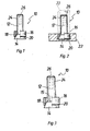
- FIG. 1 This in FIG. 1 shown, generally designated 10 fastener according to the invention has a shaft 12 with a Sp Dr Drus 14 at one end, which widens in the direction of the shaft 12 away. Furthermore, the fastening element 10 has a tubular, unslotted expansion sleeve 16, which is displaceable on the shaft 12.
- the expansion sleeve 16 and the shaft 12 with the expansion cone 14 are made of a non-rusting A4 steel, so a steel of great hardness.
- the expansion sleeve 16 has a hollow-conical widening 18 in the manner of a bevel on its inner side on its end facing the expansion cone 14.
- a cone angle of the hollow conical expansion 18 is sharper than a cone angle of the expansion cone 14, which has a cone angle of about 17 °. Due to the different cone angle, the expansion sleeve 16, when pushed onto the expansion cone 14, first sits on the expansion cone 14 with its end edge facing the expansion cone 14. The expansion sleeve 16 is thus not equal to sitting over the entire axial length of its hollow conical widening 18 with the hollow conical widening 18 on the expansion cone 14 when it is pushed onto the expansion cone 14.
- the expansion sleeve 16 can be characterized more easily expand radially outwardly at its end edge facing the expansion cone 14, when it is pushed onto the expansion cone 14.
- the different cone angle of the hollow conical widening 18 of the expansion sleeve 16 and the expansion cone 14 are exaggerated in the drawing to illustrate the different cone angles and the seating of the expansion sleeve 16 with its expansion cone 14 facing end edge on the expansion cone 14.
- the exaggerated representation of the difference in the cone angle results in the drawing, a larger annular gap between the expansion sleeve 16 and shaft 12 as it corresponds to a scale representation.
- the expansion sleeve 16 On its outer side, the expansion sleeve 16 is provided in a front region facing the expansion cone 14 with a cross knurl 20 forming a roughening.
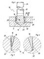
- FIG. 2 shows a fastening arrangement according to the invention by means of in FIG. 1
- the fastening element 10 is used with its expansion cone 14 in an originally cylindrical, not provided with reference numeral blind hole in a component, such as a structural steel plate 22.
- the expansion sleeve 16 is pushed onto the expansion cone 14.
- the expansion sleeve 16 With hammer blows, the expansion sleeve 16 is pushed onto the expansion cone 14, in which case the postponement is more aptly called drifting.
- the expansion sleeve 16 When pushed onto the expansion cone 14 of the expansion cone 14 expands the expansion sleeve 16 starting at its the expansion cone 14 facing end edge in the expansion cone 14 facing end portion radially outward.
- the expansion sleeve 16 presses due to their greater hardness in their spreader cone 14 facing end portion in a hole wall of the originally cylindrical and not undercut blind hole and anchored the fastener 10 positively and non-positively in the steel plate 22.
- the cross knurl 20 is pressed into the hole wall in the structural steel plate 22 and improves the anchoring of the fastener 10 in the structural steel plate 22nd
- An anchoring method provides for pushing the expansion sleeve 16 onto the expansion cone 14 by applying ultrasound to the expansion sleeve 16.
- This will be like in FIG. 2 indicated by dashed lines a tubular sonotrode 23 placed over the shaft 12 on a rear end side of the expansion sleeve 16.
- the sonotrode 23 is excited by an ultrasonic transducer, not shown, to axial vibrations in the ultrasonic frequency range and transmits the vibrations to the expansion sleeve 16.
- the expansion sleeve 16 is thereby pushed onto the expansion cone 14 and expanded, ie spread and anchored the fastener 10 in the structural steel plate 22.
- the flooding with ultrasound is quiet and claimed the mild steel plate 22 low, a counter-holder for supporting the mild steel plate 22 may be omitted.
- the anchoring of the fastening element 10 is completed when the expansion sleeve 16 is sunk flush in the structural steel slab 22. In this way, a correct anchoring of the fastener 10 is easily detected.
- the expansion sleeve 16 supports the fastener 10 against transverse loads. It should be noted that the annular gap between the expansion sleeve 16 and the shaft 12 is shown exaggerated in the drawing.
- the fastening arrangement shown is provided in a simple way a way to attach another component, not shown, to the structural steel plate 22.
- the shaft 12 has a thread 24.
- the shaft 12 may have an axial blind hole 26 through which a free end of the shaft 12 for producing a riveted connection to the outside can be flanged (not shown).
- a dowel pin having a head may be driven into the blind hole 26 to fasten another member to the structural steel plate 22 (not shown).
- Another possibility is to form the blind hole 26 with an internal thread.
- the fastener 10 requires only a small anchoring depth. With a diameter of the thread 24 of the shaft 12 in the size M 6, a diameter of the blind hole in the structural steel plate 22 of 8 mm at a blind hole depth of 5 to 6 mm is provided. There is a standardized series of fasteners 10 with shaft diameters of 4, 5, 6, 8 and 10 mm or thread diameters of the thread 24 of M4, M5, M6, M8 and M10 provided. A wall thickness of the expansion sleeve is 1 mm, with the large diameters from M8, the wall thickness can also be 1.5 mm. An outer diameter of the expansion sleeve 16 and the hole in the structural steel plate 22 is thus at the indicated diameters 6, 7, 8, 10 or 11 and 12 or 13 mm. The corresponding minimum anchoring depth t is 3.5 mm with a thread diameter of M4, 4.0 mm with a thread diameter of M5 and M6, 6.0 mm with a thread diameter of M8 and 7.0 mm with a thread diameter of M10.
- FIG. 3 illustrated fastening element 10 has at the transition from the shaft 12 to the expansion cone 14 an annular step 15 on which the expansion cone 14 passes to a smaller diameter of the shaft 12.
- the expansion cone 14 thus has at its smaller diameter, the shaft 12 facing the end of a larger diameter than the shaft 12.
- the expansion cone 14 is characterized axially shorter than an expansion cone with the same diameter on the shaft 12 facing away from the base side and with the same cone angle.
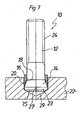
- FIG. 4 illustrated fastener 10 has as well as the two above-described fasteners 10 a Shaft 12 with an expansion cone 14 at one end, which widens in the direction of the shaft 12 away.
- the expansion sleeve 16 has an inner cone 18, which widens in the same direction as the expansion cone 14, ie in the direction of the expansion cone 14.
- the inner cone 18 is axially longer than the hollow conical widening 18 of the expansion sleeve 16 of the fastening elements 10 explained above.
- the inner cone 18 passes through the expansion sleeve 16 over a predominant part of its axial length.
- a cone angle of the inner cone 18 is sharper than a cone angle of the expansion cone 14, which has a cone angle of about 17 °. Due to the different cone angle, the expansion sleeve 16, when pushed onto the expansion cone 14, first sits on the expansion cone 14 with its end edge facing the expansion cone 14. This is in FIG. 4 left and in the enlargement in FIG.
- the expansion sleeve 16 is therefore not equal to sitting over its entire axial length with its inner cone 18 on the expansion cone 14 when it is pushed onto the expansion cone 14. As a result, the expansion sleeve 16 can be widened radially outwards at its end edge facing the expansion cone 14, when it is pushed onto the expansion cone 14.
- FIG. 4 and the magnification in FIG. 6 show a fastening arrangement according to the invention with the fastening element 10, that is, the anchored state of the fastener 10.
- the fastener 10 is used with its expansion cone 14 in an originally cylindrical, not provided with reference numeral blind hole in a component, such as a structural steel plate 22.
- the expansion sleeve 16 is pushed onto the expansion cone 14.
- Another way to widen the expansion sleeve 16 is to put a pipe section, not shown, on the shaft 12 and to screw a nut, also not shown, to a thread 24 of the shaft 12.
- the mother exerts an axial force on the expansion sleeve 16, which pushes the expansion sleeve 16 on the expansion cone 14 and expands and thereby the Fastener 10 anchored in the manner described above in the hole in the structural steel plate 22.
- This anchoring method has the advantage that no external forces act, ie the fastener 10 does not need to rest on a bottom of the hole in which it is anchored, and the fastener 10 need not be supported against the axial force exerted on the expansion sleeve 16 to expand.
- the mild steel plate 22 must therefore not be supported, as is the case when expanding the expansion sleeve 16 with hammer blows.
- the anchoring method described allows anchoring in a deep blind hole in which the fastener 10 is not seated on a hole bottom, or anchoring in a through hole.
- the expansion sleeve 16 as on the right side of FIG. 1 seen, for example, sunk about 0.5 to 1 mm in the steel plate 22. This results in a shaft 12 of the fastener 10 enclosing annular groove 26 which is filled with a sealant 28.
- the expansion cone 14 with the shaft 12 and the expansion sleeve 16 of the in FIG. 7 fastener 10 shown with the in FIG. 1 illustrated embodiment match.
- the above explanations are referred to.
- the extension 23 is cylindrical and has the same diameter as the larger diameter end of the expansion cone 14.
- the extension 23 is axially short, it has only a fraction of the length of the expansion cone 14 in the axial direction.
- the expansion cone 14 is axially shorter than a diameter of the shaft 12.
- the axial projection 23 terminates with a chamfer 25.
- An axially parallel, bead-shaped anti-rotation rib 27 counteracts a rotation of the shaft 12 and the expansion cone 14 in the expansion sleeve 16.
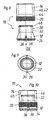
- fastener 10 has an expansion cone 12 and an expansion sleeve 14. Both consist of a steel of high hardness, in particular of an alloyed, stainless steel (for example A4 steel).
- the expansion cone 12 has, in addition to the cone on a cylindrical portion 30 at the smaller diameter end of the cone. Furthermore, the expansion cone 12 has a coaxial through-hole with internal thread 32. In an axially short section at the larger diameter end of the expansion cone 12, a diagonal or Geradrändel 34 is formed, in the drawing, a Geradrändel is shown.
- axially parallel notches 36 are formed, which form on their sides from the expansion cone 12 outwardly standing, sharp-edged ribs 38.
- the notches 36 start at the larger diameter end of the expansion cone 12 and extend axially approximately in a center of the expansion cone 12 from.
- the unslotted expansion sleeve 14 has a to the expansion cone 12 and its cylindrical portion 16 complementary through hole 40, ie, the through hole 40 of the expansion sleeve 14 has a cylindrical portion 42 and a conical portion 44, the diameter of the diameters of the expansion cone 12 and its cylindrical portion 30th correspond.
- the expansion sleeve 14 has a peripheral funnelrändel 20 which extends from a front end of the expansion sleeve 14 via an axial portion which is shorter than the conical portion 44 of the through hole 40.
- a knurl 46 on the cylindrical portion 30 of the expansion cone 12 holds the expansion sleeve 14 clamped against falling on the expansion cone 12.
- the knurl 46 forms a captive securing the expansion sleeve 14 on the expansion cone 12, which does not prevent the sliding of the expansion sleeve 14 on the expansion cone 12.
- FIG. 10 An axial length of the fastener 10 is on the order of its outer diameter, the fastener 10 is thus axially short in relation to its diameter and can be anchored in a short, not undercut blind hole.
- the expansion cone 12 of in FIGS. 8 to 10 fastener 10 shown is shaftless, ie it has no threaded shaft or the like.
- the internal thread 32 is used for fastening a component.
- the fastener 10 For anchoring in a component, such as an aluminum plate 48, the fastener 10 is inserted into a hole 50 in the aluminum plate 48, so that the expansion cone 12 is seated on a hole bottom or, in the illustrated embodiment, on a (conical) annular shoulder 52 of the hole 50 ( FIG. 11 ).
- the expansion sleeve 14 is pushed onto the expansion cone 12 and thereby widened at least in the conical region.
- the expansion of the expansion sleeve 14 by sliding on the expansion cone 12 can also be referred to as spreading.
- the expansion sleeve 14 is thereby pressed against a perforated wall, its cross knurl 20 is formed in the hole wall, so that the fastener 10 is anchored by force and frictional engagement in the hole 50 ( FIG. 12 ). Since the expansion cone 12 is shaftless, the fastener 10 does not protrude from the aluminum plate 48.
- the setting tool 54 is a cylindrical steel pin whose diameter corresponds to a diameter of the expansion sleeve 14.
- the setting tool 54 has an axial centering mandrel 56 and a tubular collar 58 surrounding the centering mandrel 56.
- the centering pin 56 dips into the internal thread 32 and thereby positions the setting tool 54 on the fastening element 10.
- the setting tool 54 sits on an end face of the expansion sleeve 14.
- Outer and inner diameter of the collar 58 correspond to the outer and inner diameter of the expansion sleeve 14.
- the expansion sleeve 14 can postpone the expansion cone 12, this delay can be referred to as driving.
- the expansion sleeve 14 can be anchored recessed in the hole 50, the fastener 10 is not made of the aluminum plate 48 before.
- a component for example a steel profile 60 to the anchored in the hole 50 in the aluminum plate 48 fastener 10 is done for example with a pushed through the steel profile 60 screw 62, which is screwed into the internal thread 32 of the expansion cone 12.
- screwing the screw 62 pulls the expansion cone 12 deeper into the expansion sleeve 14, so that the expansion sleeve 14 is more expanded and anchored.
- the knurl 20 and the notch 36 with the ribs 38 of the expansion cone 12 press when sliding the expansion sleeve 14 on the expansion cone 12 and vice versa when retracting the expansion cone 12 in the expansion sleeve 14 in the latter, they form a rotation lock that prevents the expansion cone 12 rotates when screwing the screw 62 in the expansion sleeve 14 and thereby loosens.
- the hole 50 has an anchoring portion 64 with the diameter of the expansion sleeve 14, in which the fastener 10 is anchored. With the annular shoulder 52, the hole 50 is reduced in an axial extension 66, whose diameter is at least as large as an outer diameter of the internal thread 32 of the expansion cone 12 and a thread of the screw 62.
- the extension 66 of the hole 50 allows a screwing through the screw 62 through the expansion cone 12 without the screw 62 is seated on a hole bottom and the fastener 10 is acted upon in the direction of the hole 50 out.
- This embodiment has the advantage that a screw 62, which in principle is of any length, can be used.
Description
Die Erfindung betrifft ein Befestigungselement zur Verankerung in einem kurzen, nicht hinterschnittenen Sackloch gemäß dem Oberbegriff des Anspruchs 1 und eine Anordnung mit einem derartigen Befestigungselement gemäß dem Oberbegriff des Anspruchs 12. Das Befestigungselement ist insbesondere dazu vorgesehen, eine Befestigungsmöglichkeit an einem plattenförmigen Bauteil beispielsweise aus Baustahl zu schaffen, um ein weiteres Bauteil daran befestigen zu können. Dabei soll das plattenförmige Bauteil nicht durchbohrt werden, weswegen eine nur vergleichsweise kurze Verankerungstiefe zur Verfügung steht, insbesondere wenn ein Durchmesser des Sacklochs ungefähr gleich groß wie eine Dicke des Bauteils ist. Kurz ist im Verhältnis zum Durchmesser des Sacklochs zu verstehen.The invention relates to a fastener for anchoring in a short, not undercut blind hole according to the preamble of claim 1 and an arrangement with such a fastener according to the preamble of
Aus der
Einen vergleichbaren Stand der Technik offenbart die
Die Spreizhülse der
Das Befestigungselement der
Die
Der Erfindung liegt daher die Aufgabe zugrunde, ein Befestigungselement vorzuschlagen, das in einem nicht hinterschnittenen Sackloch befestigbar ist. Dabei soll ein im Verhältnis zum Durchmesser kurzes Sackloch zur Befestigung genügen.The invention is therefore based on the object to propose a fastener which can be fastened in a non-undercut blind hole. It should be sufficient in relation to the diameter short blind hole for attachment.
Diese Aufgabe wird erfindungsgemäß durch die Merkmale des Anspruchs 1 bzw. 12 gelöst. Das erfindungsgemaße Befestigungselement weist eine rohrförmige, ungeschlitrte Spreizhülse auf, die sich auf dem Schaft befindet und auf dem Schaft verschiebbar ist. Zum Verankern im Sackloch wird das Befestigungselement mit dem Spreizkonus voraus in das Sackloch eingesetzt und die Spreizhülse auf den Spreizkonus aufgeschoben. Beim Aufschieben weitet der Spreizkonus die Spreizhülse in deren dem Spreizkonus zugewandten Stirnbereich auf. Der aufgeweitete Stirnbereich drückt sich in eine Lochwandung des Sacklochs ein und verankert dadurch das Befestigungselement im Sackloch. Es entsteht eine form- und kraftschlüssige Verbindung zwischen der im vorderen Stimbereich aufgeweiteten Spreizhülse und dem Sackloch, wodurch eine hohe Verankerungskraft auch in einem kurzen Sackloch erreicht wird. Weiterer Vorteil des erfindungsgemäßen Befestigungselements ist eine Abstützung seines Schafts gegen Querkräfte durch die Spreizhülse im Bohrloch. Des Weiteren zeigt eine bündig im Sackloch versenkte Spreizhülse eine korrekte Verankerung des Befestigungselements an, sofern das Sackloch eine vorgegebene Solltiefe aufweist. Das erfindungsgemäße Befestigungselement ist insbesondere zur Verankerung in Baustahl, Aluminium oder dgl. vorgesehen, es eignet sich aber auch zur Verankerung in anderen Werkstoffen, beispielsweise Beton. Um das Aufschieben der Spreizhülse auf den Spreizkonus und das dadurch bewirkte Aufweiten der Spreizhülse zu erleichtern kann der Spreizkonus mit einem Schmiermittel versehen sein.This object is achieved by the features of
Ebenfalls der Erleichterung der Aufweitung der Spreizhülse in ihrem dem Spreizkonus zugewandten Stirnbereich dient eine hohlkonische Aufweitung nach Art einer Fase oder eines Innenkonus auf einer Innenseite einer dem Spreizkonus zugewandten Stirnseite der Spreizhülse. Eine Materialdicke der Spreizhülse ist dadurch in dem beim Aufschieben auf den Spreizkonus sich aufweitenden Stirnbereich der Spreizhülse verringert, wodurch sich die Spreizhülse mit geringerer Kraft aufweiten lässt.Also, to facilitate the expansion of the expansion sleeve in its spreader cone facing end portion is a hollow conical widening in the manner of a chamfer or an inner cone on an inner side of the expansion cone facing end side of the expansion sleeve. A material thickness of the expansion sleeve is thereby reduced in the expanding on the expansion cone when pushing on the front region of the expansion sleeve, whereby the expansion sleeve can expand with less force.
Die hohlkonische Aufweitung der Spreizhülse weist einen spitzeren Konuswinkel als der Spreizkonus auf. Dadurch gelangt die Spreizhülse beim Aufschieben auf den Spreizkonus zuerst mit ihrem dem Spreizkonus zugewandten Stirnende in Kontakt mit dem Spreizkonus. Die Spreizhülse wird zunächst in ihrem vorderen Stirnbereich aufgeweitet und in die Lochwandung gedrückt. Erst mit zunehmendem Aufschieben auf den Spreizkonus setzt sich die Aufweitung der Spreizhülse vom vorderen, dem Spreizkonus zugewandten Stirnbereich beginnend bis in einen etwa mittleren Bereich der axial kurzen Spreizhülse fort. Die Aufweitung der Spreizhülse im vorderen Stirnbereich hat den Vorteil, dass eine Aufweitkraft klein ist, weil die Spreizhülse nur über einen kurzen Teil ihrer axialen Länge aufgeweitet wird, und dass die Kraft, mit der die Spreizhülse in die Lochwandung gedrückt ist, groß ist, weil die Spreizhülse nur im vorderen Stirnbereich und somit mit einer vergleichsweise kleinen Ringfläche in die Lochwandung eingedrückt wird. Als Vorteil ergibt sich eine stabile Verankerung bei vergleichsweise niedriger Aufweitkraft. Dieser Effekt wird unterstützt durch eine dünnwandige SpreizhülseThe hollow conical widening of the expansion sleeve has a more acute cone angle than the expansion cone. As a result, when pushed onto the expansion cone, the expansion sleeve first comes into contact with the expansion cone with its front end facing the expansion cone. The expansion sleeve is first widened in its front end area and pressed into the hole wall. Only with increasing pushing on the expansion cone, the widening of the expansion sleeve continues from the front, the expansion cone facing end region beginning in an approximately central region of the axially short expansion sleeve. The widening of the expansion sleeve in the front end region has the advantage that a Aufweitkraft is small, because the expansion sleeve is expanded only over a short part of its axial length, and that the force with which the expansion sleeve is pressed into the hole wall, because the expansion sleeve is pressed only in the front end region and thus with a comparatively small annular surface in the hole wall. The advantage is a stable anchoring at a comparatively low Aufweitkraft. This effect is supported by a thin-walled expansion sleeve
Zur Erzielung hoher Verankerungswerte hat sich ein Konuswinkel des Spreizkonus im Bereich von etwa 14° bis 20°, vorzugsweise von etwa 17° als günstig gezeigt.To achieve high anchoring values, a cone angle of the expansion cone in the range of about 14 ° to 20 °, preferably of about 17 ° has been found to be favorable.
Eine Ausgestaltung der Erfindung sieht eine Aufrauung auf einer Außenseite der Spreizhülse zumindest in deren dem Spreizkonus zugewandten Stirnbereich vor. Die Aufrauung kann beispielsweise ein Kreuzrändel sein, ungeeignet ist eine linienförmige Aufrauung wenn sie achsparallel ist. Beim Aufweiten der Spreizhülse drückt sich die Aufrauung in die Lochwandung des Sacklochs ein und erhöht dadurch die Verankerungskraft. Des Weiteren bewirkt die Aufrauung, wenn sie durch Umformen wie beispielsweise Rändeln hergestellt ist, eine Oberflächenverfestigung der Spreizhülse. Dadurch drückt sich die Aufrauung selbst dann in die Lochwandung ein, wenn die Spreizhülse und ein das Sackloch aufweisendes Bauteil aus Werkstoffen ursprünglich gleicher Härte bestehen.An embodiment of the invention provides a roughening on an outer side of the expansion sleeve, at least in their end region facing the expansion cone. The roughening can be, for example, a cross knurl, unsuitable is a line-shaped roughening when it is parallel to the axis. When expanding the expansion sleeve, the roughness presses into the hole wall of the blind hole and thereby increases the anchoring force. Furthermore, the roughening, when made by forming such as knurling, causes a surface hardening of the expansion sleeve. As a result, the roughening is pressed into the hole wall even when the expansion sleeve and a component having the blind hole are made of materials originally of the same hardness.
In bevorzugter Ausgestaltung der Erfindung weist die Spreizhülse einen Stahl großer Härte auf, beispielsweise ist sie aus einem legierten, nicht rostenden Stahl (beispielsweise A4-Stahl) hergestellt. Es genügt auch eine örtlich erhöhte Härte des Stahls außen in dem dem Spreizkonus zugewandten Stirnbereich der Spreizhülse, der sich beim Aufweiten der Spreizhülse in die Lochwandung eindrückt. Mit großer Härte ist insbesondere eine Härte der Spreizhülse gemeint, die größer ist als die Härte von Baustahl, damit sich das Befestigungselement mit hoher Verankerungskraft in Baustahl verankern lässt.In a preferred embodiment of the invention, the expansion sleeve to a steel of great hardness, for example, it is made of an alloyed, stainless steel (for example, A4 steel). It is also sufficient for a locally increased hardness of the steel outside in the expansion cone facing end region of the expansion sleeve, which presses when expanding the expansion sleeve in the hole wall. By high hardness is meant in particular a hardness of the expansion sleeve, which is greater than the hardness of structural steel, so that the fastener with high anchoring force can be anchored in structural steel.
Bei einer Weiterbildung des erfindungsgemäßen Befestigungselements weist der Spreizkonus am Übergang zum Schaft einen größeren Durchmesser als der Schaft auf, der Spreizkonus geht mit einer Ringstufe auf den kleineren Durchmesser des Schafts über. Der Spreizkonus hat also die Form eines Kegelstumpfs. Bei gleichem Durchmesser des Spreizkonus an seiner durchmessergrößeren, dem Schaft abgewandten Grundseite und bei gleichem Konuswinkel des Spreizkonus ist der Spreizkonus axial kürzer. Auch die Spreizhülse lässt sich axial entsprechend dem Spreizkonus kürzer ausbilden. Das Befestigungselement lässt sich dadurch in einem axial noch kürzeren Sackloch verankern, wobei eine Verankerungskraft bei im Übrigen gleichen Verhältnissen nahezu unverändert bleibt. Das erfindungsgemäße Befestigungselement lässt sich somit in einer noch dünneren Werkstückplatte verankern ohne dass die Werkstückplatte durchbohrt oder das Sackloch hinterschnitten werden muss.In a further development of the fastening element according to the invention, the expansion cone at the transition to the shaft has a larger diameter than the shaft, the expansion cone merges with an annular step to the smaller diameter of the shaft. The expansion cone thus has the shape of a truncated cone. With the same diameter of the expansion cone on its larger diameter, the shaft facing away from the base and the same cone angle of the expansion cone of the expansion cone is axially shorter. The expansion sleeve can be formed axially shorter according to the expansion cone. The fastening element can thereby be anchored in an axially even shorter blind hole, with an anchoring force remains virtually unchanged in otherwise the same conditions. The fastener of the invention leaves thus anchoring in an even thinner workpiece plate without having to pierce the workpiece plate or the blind hole must be undercut.
Um das Befestigungselement mit kurzer Verankerungstiefe und trotzdem hoher Verankerungskraft verankern zu können, sieht eine Ausgestaltung der Erfindung eine axial kurze Spreizhülse vor, deren Spreizbereich sich über mehr als eine Hälfte ihrer axialen Länge erstreckt. Die axiale Länge des Spreizbereichs entspricht einer axialen Länge des Innenkonus der Spreizhülse und/oder einer axialen Länge der Schlitze, sofern die Spreizhülse Schlitze aufweist. Axial kurz ist im Verhältnis zu einem charakteristischen Durchmesser des Befestigungselements zu verstehen. Charakteristische Durchmesser des Befestigungs-elements sind sein Schaftdurchmesser oder ein Außendurchmesser der unverformten Spreizhülse. Die axiale Länge der Spreizhülse entspricht bei einer Ausgestaltung der Erfindung ungefähr ihrem Außendurchmesser, bei einer weiteren Ausgestaltung der Erfindung sogar nur ungefähr 2/3 des Außendurchmessers.In order to anchor the fastener with a short anchoring depth and still high anchoring force, an embodiment of the invention provides an axially short expansion sleeve, the expansion region extends over more than half of its axial length. The axial length of the expansion region corresponds to an axial length of the inner cone of the expansion sleeve and / or an axial length of the slots, provided that the expansion sleeve has slots. Axially short is to be understood in relation to a characteristic diameter of the fastener. Characteristic diameters of the fastening element are its shaft diameter or an outer diameter of the undeformed expansion sleeve. The axial length of the expansion sleeve corresponds in one embodiment of the invention approximately its outer diameter, in a further embodiment of the invention even only about 2/3 of the outer diameter.
Eine Ausgestaltung der Erfindung sieht eine dünnwandige Spreizhülse vor. Dabei ist dünnwandig ebenfalls im Verhältnis zu einem charakteristischen Durchmesser des Befestigungselements zu sehen. Eine Wandstärke der Spreizhülse liegt beispielsweise etwa im Bereich von 1/4 bis 1/6 eines Schaftdurchmessers des Befestigungselements. Eine dünnwandige Spreizhülse lässt sich mit geringer Kraft verformen, d.h. eine zum Aufweiten der Spreizhülse erforderliche Kraft ist niedrig und eine Kraft, mit der sich die Spreizhülse in eine Lochwandung eindrückt ist bei vorgegebener Aufweitkraft groß.An embodiment of the invention provides a thin-walled expansion sleeve. In this case, thin-walled is likewise to be seen in relation to a characteristic diameter of the fastening element. A wall thickness of the expansion sleeve is for example approximately in the range of 1/4 to 1/6 of a shank diameter of the fastener. A thin-walled expansion sleeve can be deformed with little force, i. a force required for expanding the expansion sleeve is low and a force with which the expansion sleeve presses into a hole wall is large for a given expansion force.
Sitzt der Spreizkonus mit seinem dem Schaft abgewandten, im Durchmesser größeren Ende auf einem Grund eines Sacklochs auf, kann es vorkommen, dass die Spreizhülse beim Aufschieben auf den Spreizkonus am Grund des Bohrlochs aufsitzt. Dies ist insbesondere bei einem verhältnismäßig großen Durchmesser des Sacklochs der Fall, wenn ein vergleichsweise großer Ringspalt zwischen dem im Durchmesser größeren Ende des Spreizkonus und einer Lochwandung besteht. Der Grund des Sacklochs behindert das Aufschieben der Spreizhülse auf den Spreizkonus und damit das Aufweiten der Spreizhülse. Folge kann eine verschlechterte Verankerung des Befestigungselements im Sackloch sein. Deswegen sieht eine Ausgestaltung der Erfindung einen axialen Fortsatz des Schafts auf der dem Schaft abgewandten und im Durchmesser größeren Seite des Spreizkonus vor. Der Spreizkonus des erfindungemäßen Befestigungs-elements sitzt dadurch nicht mit seinem im Durchmesser größeren Ende auf dem Grund des Sacklochs auf, sondern es sitzt der axiale Fortsatz am Grund des Sacklochs auf. Der Spreizkonus hat dadurch axialen Abstand vom Grund des Sacklochs, wobei ein kurzer Abstand des Spreizkonus vom Grund des Sacklochs, d.h. ein axial kurzer Fortsatz genügt. Der axiale Fortsatz sollte kurz gehalten werden, um die notwendige Verankerungstiefe und damit die Tiefe des Sacklochs nicht unnötig zu verlängern. Durch den axialen Fortsatz wird ein axialer Abstand zwischen dem Sackloch und der Spreizhülse gewonnen, so dass der Grund des Sacklochs die axiale Verschiebung und damit die Aufweitung der Spreizhülse nicht behindert. Diese Ausgestaltung der Erfindung hat den Vorteil einer verbesserten Verankerbarkeit des Befestigungselements im Sackloch weil ein Grund des Sacklochs das Aufschieben der Spreizhülse auf den Spreizkonus und damit die Verankerung des Befestigungselements im Sackloch nicht behindert.If the expansion cone, with its end facing away from the shaft, has a larger diameter on a base of a blind hole, it can happen that the expansion sleeve is seated on the base of the borehole when pushed onto the expansion cone. This is particularly the case with a relatively large diameter of the blind hole of the case when a comparatively large annular gap between the larger diameter end of the expansion cone and a hole wall. The reason of the blind hole hinders the sliding of the expansion sleeve on the expansion cone and thus the expansion of the expansion sleeve. Result may be a deteriorated anchoring of the fastener in the blind hole. Therefore, an embodiment of the invention provides an axial extension of the shaft on the side facing away from the shaft and larger in diameter side of the expansion cone. The expansion cone of erfindungemäßen fastening element is thus not sitting with its larger diameter end on the bottom of the blind hole, but it sits on the axial extension at the bottom of the blind hole. The expansion cone thereby has axial distance from the bottom of the blind hole, with a short distance of the expansion cone from the bottom of the blind hole, ie an axially short extension is sufficient. The axial extension should be kept short in order not to unnecessarily prolong the necessary anchoring depth and thus the depth of the blind hole. By the axial extension, an axial distance between the blind hole and the expansion sleeve is obtained, so that the bottom of the blind hole does not hinder the axial displacement and thus the expansion of the expansion sleeve. This embodiment of the invention has the advantage of improved anchoring of the fastener in the blind hole because a reason of the blind hole does not hinder the sliding of the expansion sleeve on the expansion cone and thus the anchoring of the fastener in the blind hole.
Um das Aufschieben der Spreizhülse auf den Spreizkonus nicht zu behindern, darf der Fortsatz nicht seitlich über den Spreizkonus vorstehen. Insbesondere weist der Fortsatz keinen größeren Durchmesser als Spreizkonus an seinem durchmessergrößeren Ende auf. Geeignet erscheint ein zylindrischer axialer Fortsatz mit dem gleichen Durchmesser wie dem größeren Durchmesser des Spreizkonus. Auch kann sich der Fortsatz vom Spreizkonus weg verjüngen oder einen kleineren Durchmesser als der Spreizkonus aufweisen. Der axiale Fortsatz muss keinen kreisförmigen Querschnitt aufweisen.In order not to hinder the sliding of the expansion sleeve on the expansion cone, the extension must not protrude laterally beyond the expansion cone. In particular, the extension has no larger diameter than expansion cone at its larger diameter end. Suitably appears a cylindrical axial extension with the same diameter as the larger diameter of the expansion cone. Also, the extension may taper away from the expansion cone or have a smaller diameter than the expansion cone. The axial extension does not have to have a circular cross-section.
Eine geschlitzte Spreizhülse erleichtert das Aufspreizen bzw. erhöht eine Aufspreizkraft, mit der sich die Spreizhülse in eine Lochwandung eindrückt. Im Vergleich mit einer geschlitzten Spreizhülse hat eine ungeschlitzte Spreizhülse zwar den Nachteil einer größeren Aufweitkraft, jedoch den Vorteil einer größeren und in Umfangsrichtung durchgehenden nicht durch Schlitze unterbrochenen Anlage an der Lochwandung. Es wird eine ungeschlitzte Spreizhülse als erfindungsgemäß angesehen.A slotted expansion sleeve facilitates the spreading or increases a Aufspreizkraft, with which the expansion sleeve presses into a hole wall. In comparison with a slotted expansion sleeve, although an unslotted expansion sleeve has the disadvantage of a larger Aufweitkraft, but the advantage of a larger and circumferentially continuous not interrupted by slots system on the hole wall. It is considered an unslotted expansion sleeve according to the invention.
Bei einer Ausgestaltung der Erfindung weist der Spreizkörper eine achsparallel oder schräg verlaufende Riffelung zur Drehsicherung zwischen dem Spreizkonus und der Spreizhülse auf. Beim Aufschieben der Spreizhülse auf den Spreizkonus drückt sich die Riffelung des Spreizkonus in die Spreizhülse ein und bildet dadurch eine Drehsicherung. Grundsätzlich kann die Riffelung auch an einer Innenseite der Spreizhülse vorgesehen sein. Die Riffelung verläuft achsparallel oder schräg, hat also auch bei schrägem Verlauf eine achsparallele Komponente und hat damit eine Sperrwirkung gegen eine Relativbewegung zwischen Spreizhülse und Spreizkonus in Umfangsrichtung, d. h. gegen eine Drehung der Spreizhülse gegenüber dem Spreizkonus. Die Drehsicherungswirkung ist bei einer achsparallel verlaufenden Riffelung größer, dafür weist eine schräg verlaufende Riffelung zusätzlich eine Sperrwirkung gegen eine Bewegung in axialer Richtung auf, d. h. eine schräg verlaufende Riffelung hält die auf den Spreizkonus aufgeschobene Spreizhülse in axialer Richtung auf dem Spreizkonus bzw. umgekehrt den Spreizkonus in der Spreizhülse.In one embodiment of the invention, the spreader has an axially parallel or oblique corrugation for rotational security between the expansion cone and the expansion sleeve. When sliding the expansion sleeve on the expansion cone, the corrugation of the expansion cone presses into the expansion sleeve and thereby forms a rotation lock. In principle, the corrugation can also be provided on an inner side of the expansion sleeve. The corrugation runs paraxially or obliquely, so even at an oblique course an axially parallel component and thus has a barrier effect against a relative movement between the expansion sleeve and expansion cone in the circumferential direction, d. H. against rotation of the expansion sleeve relative to the expansion cone. The anti-rotation effect is greater with an axially parallel corrugation, but an inclined corrugation additionally has a blocking effect against movement in the axial direction, d. H. an obliquely extending corrugation keeps the expansion sleeve pushed onto the expansion cone in the axial direction on the expansion cone or vice versa the expansion cone in the expansion sleeve.
Wird ein Bauteil an dem verankerten Befestigungselement schraubend befestigt, übt die Schraubbewegung insbesondere beim Festziehen ein Drehmoment auf den Spreizkonus aus. Die erfindungsgemäße Riffelung erhöht ein vom Spreizkonus auf die Spreizhülse übertragbares Drehmoment, wodurch die Gefahr, dass das beim Befestigen des Bauteils auf den Spreizkonus ausgeübte Drehmoment den Spreizkonus in der Spreizhülse dreht und dadurch lockert, verringert ist. Insbesondere eine schräg verlaufende Riffelung erhöht zusätzlich den Axialsitz des Spreizkonus in der Spreizhülse, wodurch die Gefahr verringert ist, dass der Spreizkonus durch Ausüben einer Axialkraft beim Befestigen des Bauteils gelockert und aus der Spreizhülse herausgedrückt wird. Diese Gefahr besteht insbesondere dann, wenn der Spreizkonus beim Verankern nicht auf einem Bohrlochgrund aufsitzt, beispielsweise bei der Verankerung in einem Durchgangsloch oder in einem tiefen Sackloch.If a component is screwed to the anchored fastening element, the screwing movement exerts a torque on the expansion cone, in particular during tightening. The corrugation according to the invention increases a transmittable from the expansion cone on the expansion sleeve torque, whereby the risk that the torque exerted when mounting the component on the expander cone torque rotates the expansion cone in the expansion sleeve and thereby loosens is reduced. In particular, an inclined corrugation additionally increases the axial seat of the expansion cone in the expansion sleeve, whereby the risk is reduced that the expansion cone is loosened by exerting an axial force when fastening the component and pushed out of the expansion sleeve. This danger exists in particular when the expansion cone is not anchoring a bottom of a hole, for example when anchored in a through hole or in a deep blind hole.
In bevorzugter Ausgestaltung ist die Riffelung nur auf einem Axialabschnitt des Spreizkonus ausgebildet, der sich an oder nahe an dem durchmessergrößeren Ende des Spreizkonus befindet. Das Aufschieben der Spreizhülse auf den Spreizkonus ist dadurch mit geringer Kraft möglich.In a preferred embodiment, the corrugation is formed only on an axial portion of the expansion cone, which is located at or close to the larger diameter end of the expansion cone. The sliding of the expansion sleeve on the expansion cone is possible with little force.
Als Riffelung eignet sich gemäß einer Ausgestaltung der Erfindung eine Kerbung an einer oder mehreren Stellen des Umfangs des Spreizkonus. Durch Einformen der Kerbung werfen sich vergleichsweise scharfkantige Rippen oder Sicken an Seiten der Kerbung auf, die sich beim Aufschieben der Spreizhülse in diese einformen und die gewünschte Drehsicherung bewirken. Die Kerbung ist einfach herstellbar und erhöht eine Aufschiebekraft der Spreizhülse wenig.As corrugation is according to an embodiment of the invention, a notch at one or more points of the circumference of the expansion cone. By molding the notch, relatively sharp-edged ribs or beads project on the sides of the notch, which, when the expansion sleeve is pushed in, form into the notch and effect the desired rotation lock. The notch is easy to produce and increases a Aufschiebekraft the expansion sleeve little.
Eine andere Ausgestaltung der Erfindung sieht einen Gerad- oder Schrägrändel am Spreizkonus als Riffelung vor. Im Falle eines Schrägrändels verläuft die Schräge insbesondere in der gleichen Richtung wie eine Steigung eines Befestigungsgewindes, allerdings normalerweise mit abweichender Steigung. Auch ein Rändel ist einfach und preisgünstig herstellbar. Kerbung und Rändel können alternativ oder gemeinsam an dem Spreizkonus ausgebildet sein.Another embodiment of the invention provides a straight or oblique knurl on the expansion cone as corrugation. In the case of a Schrägrändels the slope runs in particular in the same direction as a slope of a fastening thread, but usually with a different pitch. Even a knurl is easy and inexpensive to produce. Notch and knurls may alternatively or jointly be formed on the expansion cone.
Eine Ausgestaltung der Erfindung sieht einen schaftlosen Spreizkonus vor, Der Spreizkonus weist beispielsweise ein Innengewinde zum Eindrehen einer Schraube oder eines Gewindebolzens vor. Schaftlos ist dahingehend zu verstehen, dass der Spreizkonus keinen aus der Spreizhülse vorstehenden Schaft aufweist. Diese Ausgestaltung der Erfindung ermöglicht ein versenktes oder mit einer Oberfläche bündiges Verankern des Befestigungselements in einem Loch. Dies hat den Vorteil, dass kein Schaft aus einem Bauteil vorsteht, in dem das Befestigungselement verankert ist. Eine Riffelung zur Drehsicherung zwischen Spreizkonus und Spreizhülse ist vorteilhaft.An embodiment of the invention provides a shaftless expansion cone, the expansion cone has, for example, an internal thread for screwing a screw or a threaded bolt. Shaftless is to be understood to mean that the expansion cone has no shaft protruding from the expansion sleeve. This embodiment of the invention allows a recessed or flush with a surface anchoring of the fastener in a hole. This has the advantage that no shank protrudes from a component in which the fastening element is anchored. A corrugation to prevent rotation between expansion cone and expansion sleeve is advantageous.
Eine Ausgestaltung der Erfindung sieht eine Verliersicherung vor, die die Spreizhülse bis zur Verankerung des Befestigungselements auf dem Spreizkonus hält. Nach der Verankerung ist die Verliersicherung bedeutungslos. Die Verliersicherung vermeidet, dass sich Spreizhülse und Spreizanker bei Lagerung und Transport voneinander trennen und hält die Spreizhülse in ihrer vorgesehenen Orientierung auf dem Spreizkonus. Die Verliersicherung vermeidet, dass die Spreizhülse verkehrt herum auf den Spreizkonus aufgesetzt wird. Ausreichend ist, dass die Verliersicherung die Spreizhülse gegen Herunterfallen auf dem Spreizkonus hält, eine unlösbare Verbindung ist nicht erforderlich. Die Verliersicherung kann beispielsweise ein Rändel sein, der die Spreizhülse mit (geringer) Klemmkraft auf dem Spreizkonus hält.An embodiment of the invention provides a captive, which holds the expansion sleeve to the anchoring of the fastener on the expansion cone. After anchoring the captive is meaningless. The captive prevents the expansion sleeve and expansion anchor during storage and transport separate from each other and holds the expansion sleeve in its intended orientation on the expansion cone. The captive avoids that the expansion sleeve is placed upside down on the expansion cone. It is sufficient that the captive holds the expansion sleeve against falling on the expansion cone, a permanent connection is not required. The captive can be, for example, a knurl, which holds the expansion sleeve with (low) clamping force on the expansion cone.
Die Ansprüche 12 bis 16 sind auf eine erfindungsgemäße Verankerung des vorstehend erläuterten Befestigungselements in einem Loch in einem Bauteil gerichtet. Diese Ansprüche werden durch die vorstehenden Erörterungen des erfindungsgemäßen Befestigungselements erläutert.
Zum Schutz vor Korrosion sieht eine erfindungsgemäße Anordnung vor, die Spreizhülse beim Verankern des Befestigungselements in einem Loch um beispielsweise etwa 0,5 bis 1 mm zu versenken. Dadurch entsteht eine den Schaft des Befestigungselements umgebende Ringnut auf einer hinteren, dem Spreizkonus abgewandten Stirnseite der Spreizhülse. In die umlaufende Nut wird erfindungsgemäß eine Dichtmasse eingebracht. Korrosion im Loch kann stattfinden, wenn und weil das Befestigungselement aus einem anderen Werkstoff als ein Bauteil besteht, in dem das Befestigungselement verankert ist. Das Befestigungselement bildet ein galvanisches Element mit dem Bauteil. Korrosion kann in diesem Fall auch auftreten, wenn sowohl das Befestigungselement als auch das Bauteil aus an sich nicht rostenden Werkstoffen bestehen, wenn also beispielsweise das Befestigungselement aus A4-Stahl und das Bauteil, in dem das Befestigungselement verankert ist, aus Aluminium (gemeint ist insbesondere eine Aluminiumlegierung) bestehen.To protect against corrosion, an arrangement according to the invention provides to sink the expansion sleeve when anchoring the fastener in a hole, for example, about 0.5 to 1 mm. This results in a surrounding the shank of the fastener annular groove on a rear, the expander cone facing away from the end of the expansion sleeve. In the circumferential groove according to the invention a sealant is introduced. Corrosion in the hole can take place if and because the fastener is made of a different material than a component in which the fastener is anchored. The fastening element forms a galvanic element with the component. Corrosion can also occur in this case, if both the fastener and the component made of stainless materials, ie if, for example, the fastener made of A4 steel and the component in which the fastener is anchored, made of aluminum (meaning in particular an aluminum alloy).
Als Verankerungstiefe genügen etwa ein Durchmesser eines Lochs, in dem das Befestigungselement verankert ist, in weiterer Ausgestaltung der Erfindung genügen sogar etwa 2/3 des Durchmessers des Lochs. Der Durchmesser des Lochs stimmt nahezu mit einem Durchmesser der unverformten Spreizhülse überein, der Durchmesser des Lochs ist vorzugsweise geringfügig größer, um die Spreizhülse mit Spiel in das Loch einbringen zu können. Die geringen Verankerungstiefen lassen sich unabhängig von der Abdichtung am Schaft des Befestigungselements verwirklichen.As anchoring depth enough about a diameter of a hole in which the fastener is anchored, in a further embodiment of the invention even suffice about 2/3 of the diameter of the hole. The diameter of the hole is nearly equal to a diameter of the undeformed expansion sleeve, the diameter of the hole is preferably slightly larger in order to bring the expansion sleeve with play in the hole can. The low anchoring depths can be realized independently of the seal on the shaft of the fastener.
Zum Aufweiten der Spreizhülse zur Verankerung des Befestigungselements in einem Loch wird eine Axialkraft auf die Spreizhülse ausgeübt, die die Spreizhülse auf den Spreizkonus schiebt. Eine zur Ausübung der Axialkraft erforderliche Reaktionskraft wird in den Schaft des Befestigungselements eingeleitet. Eine Abstützung zur Aufbringung der Axialkraft erfolgt also am Schaft des Befestigungselements. Es entsteht ein geschlossener Kraftkreislauf ohne dass äußere Kräfte auftreten. Diese Ausgestaltung hat den Vorteil, dass das Befestigungselement nicht gegen die zum Schieben der Spreizhülse auf den Spreizkonus aufzubringende Axialkraft abgestützt werden muss. Ein Bauteil, in dem das Befestigungselement verankert wird, muss also zum Verankern nicht gegengehalten werden, auch wenn das Bauteil eine dünne Platte ist. Des Weiteren lässt sich das Befestigungselement auch in einem tiefen Sackloch oder in einem Durchgangsloch verankern, weil sich der Spreizkonus nicht an einem Lochgrund abstützen muss.To widen the expansion sleeve for anchoring the fastening element in a hole, an axial force is exerted on the expansion sleeve, which pushes the expansion sleeve onto the expansion cone. A reaction force required to apply the axial force is introduced into the shaft of the fastener. A support for applying the axial force thus takes place on the shaft of the fastener. It creates a closed power circuit without external forces occur. This embodiment has the advantage that the fastening element does not have to be supported against the axial force to be applied to the expansion cone for pushing the expansion sleeve. A component in which the fastener is anchored so does not need to be countered for anchoring, even if the component is a thin plate. Furthermore, the fastener can also be anchored in a deep blind hole or in a through hole, because the expansion cone does not have to be supported on a hole bottom.
Die Reaktionskraft in den Schaft des Befestigungselements lässt sich einleiten, indem eine Mutter auf den Schaft aufgeschraubt wird. Dazu ist ein Außengewinde des Schafts erforderlich. Durch Drehen der aufgeschraubten Mutter auf dem Schaft wird die Axialkraft auf die Spreizhülse ausgeübt. Zwischen der Mutter und der Spreizhülse kann eine Hülse aufgesetzt sein, die die Axialkraft von der Mutter auf die Spreizhülse überträgt. Die Hülse ist erforderlich, wenn sich ein gewindeloser Schaftabschnitt zwischen der hinteren Stirnseite der Spreizhülse und der Mutter befindet.The reaction force in the shaft of the fastener can be initiated by a nut is screwed onto the shaft. To an external thread of the shaft is required. By turning the screwed nut on the shaft, the axial force is exerted on the expansion sleeve. Between the nut and the expansion sleeve, a sleeve may be placed, which transmits the axial force of the nut on the expansion sleeve. The sleeve is required when there is a non-threaded shank portion between the rear end face of the expansion sleeve and the nut.
Um das Befestigungselement beim Drehen der Mutter auf dem Schaft gegen Mitdrehen halten zu können sieht eine Weiterbildung des erfindungsgemäßen Verfahrens vor, zwei Kontermuttern auf den Schaft zu schrauben und gegeneinander fest zu spannen. An den Kontermuttern kann der Schaft mittels eines Mutterndrehwerkzeugs, beispielsweise eines Gabel- oder Ringschlüssels, drehfest gehalten werden.In order to hold the fastener when turning the nut on the shaft against turning provides a further development of the method according to the invention to screw two lock nuts on the shaft and to clamp against each other firmly. At the lock nuts, the shaft by means of a nut turning tool, such as a fork or ring wrench, rotatably held.
Eine Beaufschlagung der Spreizhülse mit Ultraschall zum Aufschieben auf den Spreizkonus ist möglich. Beaufschlagung mit Ultraschall meint eine Anregung der Spreizhülse mit bzw. zu mechanischen Schwingungen im Ultraschallfrequenzbereich. Vorzugsweise sind die Schwingungen axial. Die Verankerung des Befestigungselements mit Ultraschall hat die Vorteile, dass sie leise ist und den Ankergrund wenig belastet. Letzteres macht die Verankerung mit Ultraschall zur Verankerung des Befestigungselements in dünnen Platten ohne Gegenhalten geeignet. Es wird beispielsweise eine rohrförmige Sonotrode über den Schaft des Befestigungswerkzeugs auf den hinteren Stirnrand der Spreizhülse aufgesetzt, die Schwingungen von einem Ultraschallschwinger auf die Spreizhülse überträgt.An application of the expansion sleeve with ultrasound for pushing on the expansion cone is possible. Exposure to ultrasound means excitation of the expansion sleeve with or to mechanical vibrations in the ultrasonic frequency range. Preferably, the vibrations are axial. The anchoring of the fastener with ultrasound has the advantages that it is quiet and little load on the anchorage. The latter makes the anchoring with ultrasound suitable for anchoring the fastener in thin plates without holding back. For example, a tubular sonotrode is placed over the shank of the fastening tool on the rear end edge of the expansion sleeve, which transmits vibrations from an ultrasonic transducer to the expansion sleeve.
Ein Setzwerkzeug kann beispielsweise stiftförmig nach Art eines Durchschlags ausgebildet sein, so dass Hammerschläge auf die Spreizhülse des Befestigungselements übertragbar sind, die die Spreizhülse auf den Spreizkonus schieben, der beispielsweise auf einem Grund des Sacklochs aufsitzt. Mit dem Setzwerkzeug lässt sich die Spreizhülse auch beaufschlagen, wenn sie im Loch versenkt ist.A setting tool may for example be designed in the form of a pin in the manner of a punch, so that hammer blows are transferable to the expansion sleeve of the fastener, which push the expansion sleeve on the expansion cone, which is seated for example on a bottom of the blind hole. With the setting tool, the expansion sleeve can also act when it is sunk in the hole.
Die Erfindung wird nachfolgend anhand in der Zeichnung dargestellter Ausführungsbeispiele näher erläutert. Es zeigen:
- Figur 1
- ein erstes Ausführungsbeispiel eines erfindungsgemäßen Befestigungselements;
- Figur 2
- eine erfindungsgemäße Verankerung des Befestigungselements aus
Figur 1 in einem Bauteil. - Figur 3
- ein zweites Ausführungsbeispiel eines erfindungsgemäßen Befestigungselements;
- Figur 4
- ein drittes Ausführungsbeispiel eines erfindungsgemäßen Befestigungs-elements im Axialschnitt, wobei auf der linken Seite der unverankerte und auf der rechten Seite der verankerte Zustand gezeigt ist; und
- Figuren 5 und 6
- Vergrößerungen der mit Pfeilen V und VI in
Figur 4 bezeichneten Einzelheiten, wobeiFigur 5 den unverankerten undFigur 6 den verankerten Zustand des Befestigungselements zeigt; - Figur 7
- ein viertes Ausführungsbeispiel eines erfindungsgemäßen Befestigungselements in unverankertem Zustand;
- Figur 8
- einen Spreizkonus und eine Spreizhülse eines fünften Ausführungsbeispiels eines erfindungsgemäßen Befestigungselements in Seitenansicht;
- Figur 9
- eine Stirnansicht des Spreizkonus gemäß Pfeil IX in
Figur 8 ; Figur 10- das Befestigungselement aus
Figur 8 in zusammengesetztem Zustand; und - Figuren 11 bis 13
- aufeinanderfolgende Montageschritte des Befestigungs-elements aus
Figur 8 unter Zuhilfenahme eines Setzwerkzeugs.
- FIG. 1
- a first embodiment of a fastener according to the invention;
- FIG. 2
- an anchoring of the fastener according to the invention
FIG. 1 in a component. - FIG. 3
- A second embodiment of a fastener according to the invention;
- FIG. 4
- a third embodiment of a fastening element according to the invention in axial section, wherein on the left side of the anchored and on the right side of the anchored state is shown; and
- FIGS. 5 and 6
- Magnifications of the arrows V and VI in
FIG. 4 designated details, whereinFIG. 5 the floating andFIG. 6 shows the anchored state of the fastener; - FIG. 7
- A fourth embodiment of a fastener according to the invention in ungeared state;
- FIG. 8
- an expansion cone and an expansion sleeve of a fifth embodiment of a fastener according to the invention in side view;
- FIG. 9
- an end view of the expansion cone according to arrow IX in
FIG. 8 ; - FIG. 10
- from the fastener
FIG. 8 in assembled condition; and - FIGS. 11 to 13
- successive assembly steps of the fastening element
FIG. 8 with the help of a setting tool.
Das in
Die Spreizhülse 16 weist eine hohlkonische Aufweitung 18 nach Art einer Fase auf ihrer Innenseite an ihrer dem Spreizkonus 14 zugewandten Stirnseite auf. Ein Konuswinkel der hohlkonischen Aufweitung 18 ist spitzer als ein Konuswinkel des Spreizkonus 14, der einen Konuswinkel von etwa 17° aufweist. Durch die unterschiedlichen Konuswinkel sitzt die Spreizhülse 16, wenn sie auf den Spreizkonus 14 geschoben wird, zuerst mit ihrem dem Spreizkonus 14 zugewandten Stirnrand auf dem Spreizkonus 14 auf. Die Spreizhülse 16 sitzt also nicht gleich über die gesamte axiale Länge ihrer hohlkonischen Aufweitung 18 mit der hohlkonischen Aufweitung 18 auf dem Spreizkonus 14 auf, wenn sie auf den Spreizkonus 14 aufgeschoben wird. Die Spreizhülse 16 lässt sich dadurch leichter an ihrem dem Spreizkonus 14 zugewandten Stirnrand radial nach außen aufweiten, wenn sie auf den Spreizkonus 14 aufgeschoben wird. Die unterschiedlichen Konuswinkel der hohlkonischen Aufweitung 18 der Spreizhülse 16 und des Spreizkonus 14 sind in der Zeichnung übertrieben stark dargestellt um die unterschiedlichen Konuswinkel und das Aufsitzen der Spreizhülse 16 mit ihrem dem Spreizkonus 14 zugewandten Stirnrand auf dem Spreizkonus 14 zu veranschaulichen. Durch die übertriebene Darstellung des Unterschieds der Konuswinkel ergibt sich in der Zeichnung ein größerer Ringspalt zwischen Spreizhülse 16 und Schaft 12 als es einer maßstäblichen Darstellung entspricht.The
Auf ihrer Außenseite ist die Spreizhülse 16 in einem dem Spreizkonus 14 zugewandten Stirnbereich mit einem eine Aufrauung bildenden Kreuzrändel 20 versehen.On its outer side, the
Ein erfindungsgemäßes Verankerungsverfahren sieht ein Aufschieben der Spreizhülse 16 auf den Spreizkonus 14 durch Ultraschallbeaufschlagung der Spreizhülse 16 vor. Dazu wird wie in
Weist das Sackloch in der Baustahlplatte 22 eine vorgegebene Tiefe auf, dann ist die Verankerung des Befestigungselements 10 abgeschlossen, wenn die Spreizhülse 16 bündig in der Baustahlplatte 22 versenkt ist. Auf diese Weise ist eine korrekte Verankerung des Befestigungselements 10 einfach feststellbar.If the blind hole in the
Die Spreizhülse 16 stützt das Befestigungselement 10 gegen Querbeanspruchungen ab. Dabei ist zu berücksichtigen, dass der Ringspalt zwischen der Spreizhülse 16 und dem Schaft 12 in der Zeichnung übertrieben groß dargestellt ist.The
Mit der in
Das Befestigungselement 10 benötigt eine nur geringe Verankerungstiefe. Bei einem Durchmesser des Gewindes 24 des Schafts 12 in der Größe M 6 ist ein Durchmesser des Sacklochs in der Baustahlplatte 22 von 8 mm bei einer Sacklochtiefe von 5 bis 6 mm vorgesehen. Es ist eine standardisierte Baureihe der Befestigungselemente 10 mit Schaftdurchmessern von 4, 5, 6, 8 und 10 mm bzw. Gewindedurchmessern des Gewindes 24 von M4, M5, M6, M8 und M10 vorgesehen. Eine Wanddicke der Spreizhülse ist 1 mm, bei den großen Durchmessern ab M8 kann die Wanddicke auch 1,5 mm sein. Ein Außendurchmesser der Spreizhülse 16 und des Lochs in der Baustahlplatte 22 ist damit bei den angegebenen Durchmessern 6, 7, 8, 10 bzw. 11 und 12 bzw. 13 mm. Die entsprechende Mindestverankerungstiefe t ist 3,5 mm bei einem Gewindedurchmesser von M4, 4,0 mm bei einem Gewindedurchmesser von M5 und M6, 6,0 mm bei einem Gewindedurchmesser von M8 und 7,0 mm bei einem Gewindedurchmesser von M10.The
Das in
Das in
Die Spreizhülse 16 weist einen Innenkonus 18 auf, der sich in gleicher Richtung wie der Spreizkonus 14, also in Richtung des Spreizkonus 14 erweitert. Der Innenkonus 18 ist axial länger als die hohlkonische Aufweitung 18 der Spreizhülse 16 der vorstehend erläuterten Befestigungselemente 10 Der Innenkonus 18 durchsetzt die Spreizhülse 16 auf einem überwiegenden Teil ihrer axialen Länge. Ein Konuswinkel des Innenkonus 18 ist spitzer als ein Konuswinkel des Spreizkonus 14, der einen Konuswinkel von etwa 17° aufweist. Durch die unterschiedlichen Konuswinkel sitzt die Spreizhülse 16, wenn sie auf den Spreizkonus 14 geschoben wird, zuerst mit ihrem dem Spreizkonus 14 zugewandten Stirnrand auf dem Spreizkonus 14 auf. Dies ist in
Die rechte Seite von
Eine andere Möglichkeit, um die Spreizhülse 16 aufzuweiten, besteht darin, ein nicht dargestelltes Rohrstück auf den Schaft 12 aufzusetzen und eine ebenfalls nicht dargestellte Mutter auf ein Gewinde 24 des Schafts 12 zu schrauben. Über das Rohr übt die Mutter eine Axialkraft auf die Spreizhülse 16 aus, die die Spreizhülse 16 auf den Spreizkonus 14 schiebt und aufweitet und dadurch das Befestigungselement 10 in vorstehend beschriebener Weise in dem Loch in der Baustahlplatte 22 verankert. Dieses Verankerungsverfahren hat den Vorteil, dass keine äußeren Kräfte wirken, d. h. das Befestigungselement 10 muss nicht auf einem Grund des Lochs, in dem es verankert wird, aufsitzen und das Befestigungselement 10 muss nicht gegen die zum Aufweiten auf die Spreizhülse 16 ausgeübte Axialkraft abgestützt werden. Die Baustahlplatte 22 muss deswegen nicht abgestützt werden, wie es beim Aufweiten der Spreizhülse 16 mit Hammerschlägen der Fall ist. Außerdem ermöglicht das beschriebene Verankerungsverfahren eine Verankerung in einem tiefen Sackloch, in dem das Befestigungselement 10 nicht auf einem Lochgrund aufsitzt, oder die Verankerung in einem Durchgangsloch.Another way to widen the
Zur Abdichtung des Lochs in der Baustahlplatte 22 wird die Spreizhülse 16 wie auf der rechten Seite von
Der Spreizkonus 14 mit dem Schaft 12 und die Spreizhülse 16 des in
Der axiale Fortsatz 23, der den Spreizkonus 14 beim Aufschieben der Spreizhülse 16 am Grund 29 des Bohrlochs abstützt, bewirkt einen axialen Abstand der Spreizkonus 14 vom Grund 29 des Bohrlochs. Dadurch wird ein axialer Freiraum zwischen der Spreizhülse 16 und dem Grund 29 des Bohrlochs geschaffen, die Spreizhülse 16 sitzt beim Aufschieben auf den Spreizkonus 14 nicht auf dem Grund 29 des Bohrlochs auf. Das Aufweiten der Spreizhülse 16 wird deswegen nicht durch den Grund 29 des Bohrlochs behindert.The
Das in
Die ungeschlitzte Spreizhülse 14 weist ein zum Spreizkonus 12 und dessen zylindrischen Abschnitt 16 komplementäres Durchgangsloch 40 auf, d. h. das Durchgangsloch 40 der Spreizhülse 14 weist einen zylindrischen Abschnitt 42 und einen konischen Abschnitt 44 auf, deren Durchmesser den Durchmessern des Spreizkonus 12 und dessen zylindrischem Abschnitt 30 entsprechen. Auf einer Außenseite weist die Spreizhülse 14 einen umlaufenden Kreuzrändel 20 auf, der sich von einem Stirnende der Spreizhülse 14 über einen Axialabschnitt erstreckt, der kürzer als der konische Abschnitt 44 des Durchgangslochs 40 ist. Beim Verankern drückt sich der Kreuzrändel 20 wie bereits beschrieben in eine Lochwandung ein und verbessert dadurch die Verankerung des Befestigungselements 10 durch Formschluss.The
Ein Rändel 46 am zylindrischen Abschnitt 30 des Spreizkonus 12 hält die Spreizhülse 14 klemmend gegen Herunterfallen auf den Spreizkonus 12. Der Rändel 46 bildet eine Verliersicherung der Spreizhülse 14 auf dem Spreizkonus 12, die das Aufschieben der Spreizhülse 14 auf den Spreizkonus 12 nicht verhindert.A
Der Spreizkonus 12 des in
Zur Verankerung in einem Bauteil, beispielsweise einer Aluminiumplatte 48 wird das Befestigungselement 10 in ein Loch 50 in der Aluminiumplatte 48 eingesetzt, so dass der Spreizkonus 12 auf einen Lochgrund oder, im dargestellten Ausführungsbeispiel, auf einer (konischen) Ringschulter 52 des Lochs 50 aufsitzt (
Zum Aufschieben der Spreizhülse 14 auf den Spreizkonus 12 ist das in
Die Befestigung eines Bauteils, beispielsweise eines Stahlprofils 60 an dem im Loch 50 in der Aluminiumplatte 48 verankerten Befestigungselement 10 erfolgt beispielsweise mit einer durch das Stahlprofil 60 durchgesteckten Schraube 62, die in das Innengewinde 32 des Spreizkonus 12 eingedreht wird. Beim Eindrehen zieht die Schraube 62 den Spreizkonus 12 tiefer in die Spreizhülse 14 ein, so dass die Spreizhülse 14 stärker aufgeweitet und verankert wird. Der Rändel 20 und die Kerbung 36 mit den Rippen 38 des Spreizkonus 12 drücken sich beim Aufschieben der Spreizhülse 14 auf den Spreizkonus 12 bzw. umgekehrt beim Einziehen des Spreizkonus 12 in die Spreizhülse 14 in letztere ein, sie bilden eine Drehsicherung, die verhindert, dass sich der Spreizkonus 12 beim Eindrehen der Schraube 62 in der Spreizhülse 14 dreht und dadurch lockert.The attachment of a component, for example a
Das Loch 50 weist einen Verankerungsabschnitt 64 mit dem Durchmesser der Spreizhülse 14 auf, in dem das Befestigungselement 10 verankert ist. Mit der Ringschulter 52 verkleinert sich das Loch 50 in einen axialen Fortsatz 66, dessen Durchmesser mindestens so groß wie ein Außendurchmesser des Innengewindes 32 des Spreizkonus 12 bzw. eines Gewindes der Schraube 62 ist. Der Fortsatz 66 des Lochs 50 ermöglicht ein Durchschrauben der Schraube 62 durch den Spreizkonus 12 ohne dass die Schraube 62 an einem Lochgrund aufsitzt und das Befestigungselement 10 in Richtung aus dem Loch 50 heraus beaufschlagt. Diese Ausgestaltung hat den Vorteil, dass eine im Prinzip beliebig lange Schraube 62 verwendet werden kann.The hole 50 has an anchoring portion 64 with the diameter of the
Claims (16)
- Fixing element for anchoring in a short, non-undercut, blind hole, having a shank (12) which has at one end an expander cone (14) which widens in the direction away from the shank (12), and having a non-slotted, tubular expansion sleeve (16), through which the shank (12) extends and which is arranged to be pushed up onto the expander cone (14) for widening out and anchoring in the blind hole so that it widens out in an end region towards the expander cone 14, characterised in that the expansion sleeve (16) has on the inside of its end face towards the expander cone (14) a hollow conical widening-out (18) such that, before being pushed up onto the expander cone (14), the hollow conical widening-out (18) of the expansion sleeve (16) has a more acute cone angle than the expander cone (14).
- Fixing element according to claim 1, characterised in that the expander cone (14) has a cone angle of from about 14° to 20°, preferably of about 17°.
- Fixing element according to claim 1, characterised in that the expansion sleeve (16) has a roughened region (20) on the outside in its end region towards the expander cone (14).
- Fixing element according to claim 1, characterised in that the fixing element (10) comprises at least on the outside in the end region of the expansion sleeve (16) towards the expander cone (14) a steel of high hardness.
- Fixing element according to claim 1, characterised in that the expander cone (14) has, at the transition to the shank (12), a larger diameter than the shank (12); and in that the transition from the expander cone (14) to the smaller diameter of the shank is effected by means of an annular step (15).
- Fixing element according to claim 1, characterised in that the expansion sleeve (16) is axially short and has an expansion region which extends over more than half of the axial length of the expansion sleeve (16).
- Fixing element according to claim 1, characterised in that the fixing element (10) has a thin-walled expansion sleeve (16).
- Fixing element according to claim 1, characterised in that the shank (12) has an axial prolongation (23) on that side of the expander cone (14) which is remote from the shank (12), for supporting the expander cone (14) on the bottom (29) of the blind hole when the expansion sleeve (16) is being pushed up.
- Fixing element according to claim 8, characterised in that the prolongation (23) does not project laterally beyond the expander cone (14).
- Fixing element according to claim 1, characterised in that, for preventing rotation between the expander cone (14) and the expansion sleeve (16), the expander cone (14) has fluting (34, 36, 38) that extends axially parallel or obliquely.
- Fixing element according to claim 1, characterised in that the expander cone (14) has a retaining means (46) for holding the expansion sleeve (16) on the expander cone (14).
- Arrangement having a fixing element (10) according to one of claims 1 to 11 which is anchored in a non-undercut hole in a component (22), wherein the fixing element (10) comprises the shank (12) having at one end the expander cone (14), which widens in the direction away from the shank (12), and the non-slotted, tubular expansion sleeve (16), through which the shank (12) extends and which is pushed up onto the expander cone (14) located in the hole in the component (22) so that the expansion sleeve (16) is widened out in the end region towards the expander cone (14) and pressed into the wall of the hole in the component (22) and the fixing element (10) is anchored in the component (22), characterised in that, before being pushed up onto the expander cone (14), the hollow conical widening-out (18) of the expansion sleeve (16) has a more acute cone angle than the expander cone (14).
- Arrangement according to claim 12, characterised in that the expansion sleeve (16), at least on the outside in its end region towards the expander cone (14) and pressed into the wall of the hole in the component (22), has a greater hardness than the component (22).
- Arrangement according to claim 12, characterised in that the anchoring depth of the fixing element (10) in the hole in the component (22) is not greater than but preferably smaller than the diameter of the hole.
- Arrangement according to claim 12, characterised in that the expansion sleeve (16) is recessed in the hole in the component (22); and in that an annular groove (26) formed by the recessing of the expansion sleeve (16) and surrounding the shank (12) has a sealing mass (28).
- Arrangement according to claim 12, characterised in that the expander cone (14) has an internal thread (32); in that the hole (50) in the component (48) is stepped and has an anchoring portion (64), the diameter of which corresponds to the external diameter of the expansion sleeve (16) and in which the expander cone (14) and expansion sleeve (16) are anchored; and in that the hole (50) has an axial prolongation (66), the diameter of which is smaller than the diameter of the anchoring portion (64) and the diameter of which is at least as large as the external diameter of the internal thread (32) of the expander cone (14).
Applications Claiming Priority (6)
| Application Number | Priority Date | Filing Date | Title |
|---|---|---|---|
| DE2003145118 DE10345118A1 (en) | 2003-09-26 | 2003-09-26 | Fastening element for anchoring in a short blind hole located in a structural steel plate comprises a tubular expandable sleeve through which a shaft extends |
| DE2003148655 DE10348655A1 (en) | 2003-09-26 | 2003-10-15 | Fastening element for anchoring in a short blind hole located in a structural steel plate comprises a tubular expandable sleeve through which a shaft extends |
| DE2003153237 DE10353237A1 (en) | 2003-09-26 | 2003-11-13 | Fastening element for anchoring in a short blind hole located in a structural steel plate comprises a tubular expandable sleeve through which a shaft extends |
| DE2003157702 DE10357702A1 (en) | 2003-09-26 | 2003-12-09 | Fastening element for anchoring in a short blind hole located in a structural steel plate comprises a tubular expandable sleeve through which a shaft extends |
| DE200410003943 DE102004003943A1 (en) | 2003-09-26 | 2004-01-26 | Fastening element for anchoring in a short blind hole located in a structural steel plate comprises a tubular expandable sleeve through which a shaft extends |
| PCT/EP2004/010556 WO2005031176A1 (en) | 2003-09-26 | 2004-09-21 | Fastening element to be anchored in a short blind hole that is not undercut, arrangement comprising such a fastening element, method and placement tool for anchoring such a fastening element |
Publications (2)
| Publication Number | Publication Date |
|---|---|
| EP1664558A1 EP1664558A1 (en) | 2006-06-07 |
| EP1664558B1 true EP1664558B1 (en) | 2014-09-10 |
Family
ID=34397203
Family Applications (1)
| Application Number | Title | Priority Date | Filing Date |
|---|---|---|---|
| EP04765435.5A Not-in-force EP1664558B1 (en) | 2003-09-26 | 2004-09-21 | Fastening element to be anchored in a short blind hole that is not undercut, arrangement comprising such a fastening element, method and placement tool for anchoring such a fastening element |
Country Status (3)
| Country | Link |
|---|---|
| EP (1) | EP1664558B1 (en) |
| HK (1) | HK1097893A1 (en) |
| WO (1) | WO2005031176A1 (en) |
Families Citing this family (4)
| Publication number | Priority date | Publication date | Assignee | Title |
|---|---|---|---|---|
| DE102006047283A1 (en) * | 2006-10-06 | 2008-04-10 | Fischerwerke Artur Fischer Gmbh & Co. Kg | Ultrasound anchor and setting method |
| DE102006048749A1 (en) * | 2006-10-12 | 2008-04-17 | Fischerwerke Artur Fischer Gmbh & Co. Kg | Piloted counterbore for manufacturing blind hole, has contact surface with diameter of counterbore, where contact surface is coaxial to intended rotational axis of counterbore, and casing arranged on shaft |
| FR2972508B1 (en) * | 2011-03-07 | 2014-09-19 | Prospection & Inventions | EXPANSION SOCKET ANKLE |
| GB2575105A (en) | 2018-06-29 | 2020-01-01 | Airbus Operations Ltd | A duct stringer |
Family Cites Families (6)
| Publication number | Priority date | Publication date | Assignee | Title |
|---|---|---|---|---|
| FR1010775A (en) * | 1952-07-24 | 1952-06-16 | Fixing device | |
| FR1297330A (en) * | 1961-05-19 | 1962-06-29 | Louis Colin & Fils | Method of fixing mechanical parts on supports mainly soft material supports |
| DE1450993A1 (en) * | 1965-03-02 | 1969-04-10 | Artur Fischer | Duebel for securely fastening objects in building materials |
| DE2548495A1 (en) * | 1974-11-01 | 1976-05-06 | Adbar Patent Co Ltd | COMMITMENT |
| US4919579A (en) * | 1987-08-24 | 1990-04-24 | Kabushiki Kaisha Miyanaga | Anchor construction and method of manufacture |
| JP4258745B2 (en) * | 1997-03-21 | 2009-04-30 | ウッドウェルディング アーゲー | Fastening method for joining element in material having hole or void and joining element for fastening |
-
2004
- 2004-09-21 WO PCT/EP2004/010556 patent/WO2005031176A1/en active Application Filing
- 2004-09-21 EP EP04765435.5A patent/EP1664558B1/en not_active Not-in-force
-
2007
- 2007-04-19 HK HK07104127.1A patent/HK1097893A1/en not_active IP Right Cessation
Also Published As
| Publication number | Publication date |
|---|---|
| HK1097893A1 (en) | 2007-07-06 |
| EP1664558A1 (en) | 2006-06-07 |
| WO2005031176A1 (en) | 2005-04-07 |
Similar Documents
| Publication | Publication Date | Title |
|---|---|---|
| EP2567107B1 (en) | Expanding anchor and method for anchoring an expanding anchor | |
| EP2689147B1 (en) | Expansion anchor | |
| EP1557574B1 (en) | Blind rivet nut | |
| DE102011007570A1 (en) | expansion anchor | |
| CH656193A5 (en) | SPREADING DOWEL. | |
| EP0192913A1 (en) | Expansive dowel with an application indication | |
| WO2000047363A1 (en) | Support system for functional unit | |
| DE3607607A1 (en) | FIXING SEALING SHEETS AND / OR INSULATION PANELS ON THE FLAT ROOF AND THEREFORE SPECIFIC FASTENING DEVICE | |
| EP1664558B1 (en) | Fastening element to be anchored in a short blind hole that is not undercut, arrangement comprising such a fastening element, method and placement tool for anchoring such a fastening element | |
| EP1412644B1 (en) | Straddling dowel | |
| EP2627915B1 (en) | Anchoring device for fastening a component to a carrier element | |
| DE19520130A1 (en) | Form-fit undercut anchor | |
| DE3139174C2 (en) | Anchor bolts | |
| EP3936730A1 (en) | Function element | |
| DE102004003943A1 (en) | Fastening element for anchoring in a short blind hole located in a structural steel plate comprises a tubular expandable sleeve through which a shaft extends | |
| EP2668406B1 (en) | Fixing element | |
| DE10353237A1 (en) | Fastening element for anchoring in a short blind hole located in a structural steel plate comprises a tubular expandable sleeve through which a shaft extends | |
| WO2005100805A1 (en) | Fastening element | |
| DE19820140A1 (en) | Attachment of masts for traffic lights or the like | |
| DE10357702A1 (en) | Fastening element for anchoring in a short blind hole located in a structural steel plate comprises a tubular expandable sleeve through which a shaft extends | |
| EP0610465B1 (en) | Securing device | |
| WO2015154980A1 (en) | Connection device and connection with connection device | |
| EP4119806A1 (en) | Expansion anchor and arrangement with the expansion anchor | |
| EP1510705B1 (en) | Fastening bolt and fastening device with fastening bolt and a self locking collar | |
| EP0893610B1 (en) | Expansion dowel |
Legal Events
| Date | Code | Title | Description |
|---|---|---|---|
| PUAI | Public reference made under article 153(3) epc to a published international application that has entered the european phase |
Free format text: ORIGINAL CODE: 0009012 |
|
| 17P | Request for examination filed |
Effective date: 20060217 |
|
| AK | Designated contracting states |
Kind code of ref document: A1 Designated state(s): AT BE BG CH CY CZ DE DK EE ES FI FR GB GR HU IE IT LI LU MC NL PL PT RO SE SI SK TR |
|
| 17Q | First examination report despatched |
Effective date: 20060719 |
|
| DAX | Request for extension of the european patent (deleted) | ||
| RAP1 | Party data changed (applicant data changed or rights of an application transferred) |
Owner name: FISCHERWERKE GMBH & CO. KG |
|
| GRAP | Despatch of communication of intention to grant a patent |
Free format text: ORIGINAL CODE: EPIDOSNIGR1 |
|
| INTG | Intention to grant announced |
Effective date: 20140218 |
|
| GRAP | Despatch of communication of intention to grant a patent |
Free format text: ORIGINAL CODE: EPIDOSNIGR1 |
|
| GRAS | Grant fee paid |
Free format text: ORIGINAL CODE: EPIDOSNIGR3 |
|
| INTG | Intention to grant announced |
Effective date: 20140709 |
|
| GRAA | (expected) grant |
Free format text: ORIGINAL CODE: 0009210 |
|
| AK | Designated contracting states |
Kind code of ref document: B1 Designated state(s): AT BE BG CH CY CZ DE DK EE ES FI FR GB GR HU IE IT LI LU MC NL PL PT RO SE SI SK TR |
|
| REG | Reference to a national code |
Ref country code: GB Ref legal event code: FG4D Free format text: NOT ENGLISH |
|
| REG | Reference to a national code |
Ref country code: CH Ref legal event code: EP |
|
| REG | Reference to a national code |
Ref country code: IE Ref legal event code: FG4D Free format text: LANGUAGE OF EP DOCUMENT: GERMAN |
|
| REG | Reference to a national code |
Ref country code: AT Ref legal event code: REF Ref document number: 686843 Country of ref document: AT Kind code of ref document: T Effective date: 20141015 |
|
| REG | Reference to a national code |
Ref country code: DE Ref legal event code: R096 Ref document number: 502004014717 Country of ref document: DE Effective date: 20141016 |
|
| PGFP | Annual fee paid to national office [announced via postgrant information from national office to epo] |
Ref country code: DE Payment date: 20140916 Year of fee payment: 11 |
|
| RAP2 | Party data changed (patent owner data changed or rights of a patent transferred) |
Owner name: FISCHERWERKE GMBH & CO. KG |
|
| PG25 | Lapsed in a contracting state [announced via postgrant information from national office to epo] |
Ref country code: FI Free format text: LAPSE BECAUSE OF FAILURE TO SUBMIT A TRANSLATION OF THE DESCRIPTION OR TO PAY THE FEE WITHIN THE PRESCRIBED TIME-LIMIT Effective date: 20140910 Ref country code: GR Free format text: LAPSE BECAUSE OF FAILURE TO SUBMIT A TRANSLATION OF THE DESCRIPTION OR TO PAY THE FEE WITHIN THE PRESCRIBED TIME-LIMIT Effective date: 20141211 Ref country code: SE Free format text: LAPSE BECAUSE OF FAILURE TO SUBMIT A TRANSLATION OF THE DESCRIPTION OR TO PAY THE FEE WITHIN THE PRESCRIBED TIME-LIMIT Effective date: 20140910 Ref country code: ES Free format text: LAPSE BECAUSE OF FAILURE TO SUBMIT A TRANSLATION OF THE DESCRIPTION OR TO PAY THE FEE WITHIN THE PRESCRIBED TIME-LIMIT Effective date: 20140910 |
|
| REG | Reference to a national code |
Ref country code: NL Ref legal event code: VDEP Effective date: 20140910 |
|
| PG25 | Lapsed in a contracting state [announced via postgrant information from national office to epo] |
Ref country code: CY Free format text: LAPSE BECAUSE OF FAILURE TO SUBMIT A TRANSLATION OF THE DESCRIPTION OR TO PAY THE FEE WITHIN THE PRESCRIBED TIME-LIMIT Effective date: 20140910 |
|
| PG25 | Lapsed in a contracting state [announced via postgrant information from national office to epo] |
Ref country code: NL Free format text: LAPSE BECAUSE OF FAILURE TO SUBMIT A TRANSLATION OF THE DESCRIPTION OR TO PAY THE FEE WITHIN THE PRESCRIBED TIME-LIMIT Effective date: 20140910 |
|
| PG25 | Lapsed in a contracting state [announced via postgrant information from national office to epo] |
Ref country code: PT Free format text: LAPSE BECAUSE OF FAILURE TO SUBMIT A TRANSLATION OF THE DESCRIPTION OR TO PAY THE FEE WITHIN THE PRESCRIBED TIME-LIMIT Effective date: 20150112 Ref country code: EE Free format text: LAPSE BECAUSE OF FAILURE TO SUBMIT A TRANSLATION OF THE DESCRIPTION OR TO PAY THE FEE WITHIN THE PRESCRIBED TIME-LIMIT Effective date: 20140910 Ref country code: SK Free format text: LAPSE BECAUSE OF FAILURE TO SUBMIT A TRANSLATION OF THE DESCRIPTION OR TO PAY THE FEE WITHIN THE PRESCRIBED TIME-LIMIT Effective date: 20140910 Ref country code: CZ Free format text: LAPSE BECAUSE OF FAILURE TO SUBMIT A TRANSLATION OF THE DESCRIPTION OR TO PAY THE FEE WITHIN THE PRESCRIBED TIME-LIMIT Effective date: 20140910 Ref country code: RO Free format text: LAPSE BECAUSE OF FAILURE TO SUBMIT A TRANSLATION OF THE DESCRIPTION OR TO PAY THE FEE WITHIN THE PRESCRIBED TIME-LIMIT Effective date: 20140910 |
|
| REG | Reference to a national code |
Ref country code: CH Ref legal event code: PL |
|
| PG25 | Lapsed in a contracting state [announced via postgrant information from national office to epo] |
Ref country code: PL Free format text: LAPSE BECAUSE OF FAILURE TO SUBMIT A TRANSLATION OF THE DESCRIPTION OR TO PAY THE FEE WITHIN THE PRESCRIBED TIME-LIMIT Effective date: 20140910 |
|
| REG | Reference to a national code |
Ref country code: DE Ref legal event code: R097 Ref document number: 502004014717 Country of ref document: DE |
|
| REG | Reference to a national code |
Ref country code: IE Ref legal event code: MM4A |
|
| PG25 | Lapsed in a contracting state [announced via postgrant information from national office to epo] |
Ref country code: BE Free format text: LAPSE BECAUSE OF NON-PAYMENT OF DUE FEES Effective date: 20140930 Ref country code: MC Free format text: LAPSE BECAUSE OF FAILURE TO SUBMIT A TRANSLATION OF THE DESCRIPTION OR TO PAY THE FEE WITHIN THE PRESCRIBED TIME-LIMIT Effective date: 20140910 |
|
| PLBE | No opposition filed within time limit |
Free format text: ORIGINAL CODE: 0009261 |
|
| STAA | Information on the status of an ep patent application or granted ep patent |
Free format text: STATUS: NO OPPOSITION FILED WITHIN TIME LIMIT |
|
| PG25 | Lapsed in a contracting state [announced via postgrant information from national office to epo] |
Ref country code: DK Free format text: LAPSE BECAUSE OF FAILURE TO SUBMIT A TRANSLATION OF THE DESCRIPTION OR TO PAY THE FEE WITHIN THE PRESCRIBED TIME-LIMIT Effective date: 20140910 Ref country code: LI Free format text: LAPSE BECAUSE OF NON-PAYMENT OF DUE FEES Effective date: 20140930 Ref country code: CH Free format text: LAPSE BECAUSE OF NON-PAYMENT OF DUE FEES Effective date: 20140930 |
|
| REG | Reference to a national code |
Ref country code: FR Ref legal event code: ST Effective date: 20150710 |
|
| 26N | No opposition filed |
Effective date: 20150611 |
|
| GBPC | Gb: european patent ceased through non-payment of renewal fee |
Effective date: 20141210 |
|
| PG25 | Lapsed in a contracting state [announced via postgrant information from national office to epo] |
Ref country code: IE Free format text: LAPSE BECAUSE OF NON-PAYMENT OF DUE FEES Effective date: 20140921 Ref country code: IT Free format text: LAPSE BECAUSE OF FAILURE TO SUBMIT A TRANSLATION OF THE DESCRIPTION OR TO PAY THE FEE WITHIN THE PRESCRIBED TIME-LIMIT Effective date: 20140910 |
|
| PG25 | Lapsed in a contracting state [announced via postgrant information from national office to epo] |
Ref country code: GB Free format text: LAPSE BECAUSE OF NON-PAYMENT OF DUE FEES Effective date: 20141210 |
|
| REG | Reference to a national code |
Ref country code: AT Ref legal event code: MM01 Ref document number: 686843 Country of ref document: AT Kind code of ref document: T Effective date: 20140921 |
|
| PG25 | Lapsed in a contracting state [announced via postgrant information from national office to epo] |
Ref country code: FR Free format text: LAPSE BECAUSE OF NON-PAYMENT OF DUE FEES Effective date: 20141112 Ref country code: SI Free format text: LAPSE BECAUSE OF FAILURE TO SUBMIT A TRANSLATION OF THE DESCRIPTION OR TO PAY THE FEE WITHIN THE PRESCRIBED TIME-LIMIT Effective date: 20140910 |
|
| PG25 | Lapsed in a contracting state [announced via postgrant information from national office to epo] |
Ref country code: AT Free format text: LAPSE BECAUSE OF NON-PAYMENT OF DUE FEES Effective date: 20140921 |
|
| REG | Reference to a national code |
Ref country code: DE Ref legal event code: R119 Ref document number: 502004014717 Country of ref document: DE |
|
| PG25 | Lapsed in a contracting state [announced via postgrant information from national office to epo] |
Ref country code: BG Free format text: LAPSE BECAUSE OF FAILURE TO SUBMIT A TRANSLATION OF THE DESCRIPTION OR TO PAY THE FEE WITHIN THE PRESCRIBED TIME-LIMIT Effective date: 20140910 |
|
| PG25 | Lapsed in a contracting state [announced via postgrant information from national office to epo] |
Ref country code: DE Free format text: LAPSE BECAUSE OF NON-PAYMENT OF DUE FEES Effective date: 20160401 Ref country code: TR Free format text: LAPSE BECAUSE OF FAILURE TO SUBMIT A TRANSLATION OF THE DESCRIPTION OR TO PAY THE FEE WITHIN THE PRESCRIBED TIME-LIMIT Effective date: 20140910 Ref country code: HU Free format text: LAPSE BECAUSE OF FAILURE TO SUBMIT A TRANSLATION OF THE DESCRIPTION OR TO PAY THE FEE WITHIN THE PRESCRIBED TIME-LIMIT; INVALID AB INITIO Effective date: 20040921 Ref country code: LU Free format text: LAPSE BECAUSE OF NON-PAYMENT OF DUE FEES Effective date: 20140921 |